1
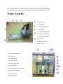
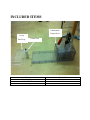
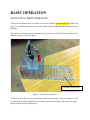
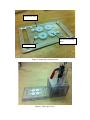
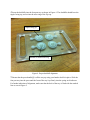
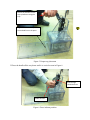
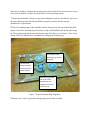
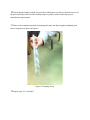
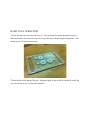
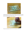
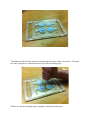
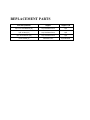
Good job overall, and good use of pictures to illustrate the operation.
The Maintenance section could be improved with pictures and the
replacement parts list is incomplete.
Mechanical Frappe Press
Operation Manual
CONTENTS
OPERATIONAL INSTRUCTIONS
PRECAUTIONS
PART NAMES
INCLUDED ITEMS
BASIC OPERATION
MAINTENANCE
REPLACEMENT PARTS
Thank you for using The Frapptastic
Five Mechanical Frappe Press.
Please read this manual carefully
before operating
This manual should be kept in a safe
place for referencing its uses.
PRECAUTIONS
WARNINGS BEFORE USE
1 Never insert hands or other body parts inside the moving components. Doing so, could result
in injury if the press handle were to fall or be pressed down.
2 Do not use press for anything other than the intended use. Pressing objects other than Frappe
valves could damage or break the press, which could potentially cause injury to the user.
3 Keep your hands and other body parts away from moving parts, especially on the handle,
when the press is in use. Failure to do so could result in pinching or more serious injury.
4 Only use the press on a sturdy level surface. If operating on a portable table, the structure must
be able to withstand 35lb. Failure to do so could cause the press to work improperly or fall,
potentially causing injury.
5 Never allow someone else to press the handle while you are handling the tray. Serious injury
can occur.
6 Do not operate the press without the front and back safety guard on. Failure to do so could
cause extra risk of injury to the user and increase the chance of damage to the press.
7 If pain or discomfort occurs during use, stop and consult a medical professional before
continuing use.
CAUTIONS FOR USE
1 Always inspect press components such as trays, outside double press cylinders, top and
bottom press plates, vertical mounting plate, and front and rear triangle supports, and scan other
areas for cracks or malfunctioning parts before and during use. Damaged or malfunctioning parts
could cause the press to work improperly or break.
2 If the alignment pins do not properly line up with the tray, maintenance may need to be
performed before using press (see the Maintenance section of this manual. NEVER force the
press down. Doing so may cause damage to the press and injury to the user.
3 Check to ensure the non-slip surface on the bottom of the press is not worn or torn prior to use.
If the non-slip surface is damaged the press may slip and cause injury.
4 Never disassemble or reassemble the press without proper training. Disassembling or
reassembling the press without proper training could cause alignment or safety issues.
PART NAMES
1 Four Part Tray
2 Front Guard
3 Top Mounting Plate
4 Press Handle
5 Vertical Mounting Plate
6 Front Triangle Support
7 Rear Triangle Support
8 Rear Guard
9 Side Guide Plate
10 Base Plate
11 3/8-16 Threaded Rod
12 3/8-16 Nut
13 3/8 ID Washer
14 Top Press Plate
15 Bottom Press Plate
16 Alignment Pin
17 Outside Double Press Cylinder
18 Compression Spring
19 Spring Plunger
20 Base Bushings
INCLUDED ITEMS
1 Mechanical
Frappe Press
5 Four
Part Trays
1 Hand Tool
Part
Four Part Tray
Hand Tool
Mechanical Frappe Press
Quantity
5
2
1
BASIC OPERATION
MECHANICAL PRESS OPERATION
1 Place the mechanical press on a sturdy, level surface with the given non-slip pads. Ensure the
press is in a comfortable position to press the handle without adding unneeded stress to the arm
and body.
2 For ease of operation, place the four part tray[1] on the base plate[10] before the flip caps are
added to the tray, as seen in Figure 1.
Tray slides into Base Plate
Figure 1. Tray Placement in Press
3 Take four clean flip caps and insert them into the four part tray[1] as shown in Figure 2. The
cap should fit into the designated cap slot. Make sure that the outer lip of the cap sits on top of
the tray with the flat part facing down.
Outer Lip on Tray
Flat Part of Cap Facing
Down
Cap in Cap slot
Figure 2. Proper Flip Cap Placement
Figure 3. Flip Caps in Tray
4 Insert the duckbills into the four part tray as shown in Figure 4. The duckbills should have the
nipple facing up, and set into the outer ring of the flip cap.
Nipple Facing Up
Duckbill set inside outer ring
Figure 4. Proper duckbill alignment
5 Ensure that the press handle[4] is all the way up using your hand to hold it in place. Slide the
four part tray into the press until the front of the tray lays firmly into the spring steel indicator.
For further indication of alignment, make sure that the back of the tray is flush with the marked
line as seen in Figure 5.
Ensure the handle is all the
way up before moving the
tray.
Align the back of the tray with
the marked line on the press.
Figure 5. Proper tray placement
6 Press the handle all the way down until it is vertical as seen in Figure 6.
Press linkage
should be linear
Handle Vertical
Figure 6. Press in down position
If the user is unable to complete the pressing motion, please pull the tray out and remove one or
more of the assemblies to reduce the required force for the pressing motion.
7 Ensure that the handle is all the way up before sliding the tray back out. Slide the tray out of
the press and inspect that all of the duckbills are properly seated in the flip caps per
manufacturer’s requirements.
8 Place the retaining rings on the duckbills with the slots properly lined up with the duckbill
nipples. Each of the retaining rings should rest on top of the duckbills with the flat side facing
up. The retaining ring should set inside the outer ring of the flip cap. Use Figure 7 for a visual.
Always follow the manufacturer’s standards for lining up the retaining ring.
The flat part of the
retaining ring must be
facing up.
The slit in the
duckbill must be
lined up with the
duckbill nipple.
Retaining ring should
set on top of the
duckbill and rest
inside the outer ring
of the flip cap.
Figure 7. Proper Retaining Ring Alignment
9 Repeat steps 5 and 6 to press the retaining rings into the final assembly.
10 Ensure that the handle is all the way up before sliding the tray back out. Slide the tray out of
the press and inspect that all of the retaining rings are properly seated in the flip caps per
manufacturers requirements.
11 Remove the completed assembly by dumping the parts into their assigned completed parts
box for inspection as shown in Figure 8.
Figure 8. Dumping of tray
12 Repeat steps 2-11 as needed.
HAND TOOL OPERATION
1 Insert four flip caps into Four Part Tray [1].
The cap should fit into the designated cap slot.
Make sure that the outer lip of the cap sits on top of the tray with the flat part facing down. Also
shown in step 3 of the press operation.
2 Insert the duck bills into the flip caps.
Align the nipple on the duck bill with the lid on the flip
cap. Also shown in step 4 of the press operation.
3 Hold hand tool by the base and press duck bills into place vertically while using a rolling
motion to seat the entire duck bill into the flip cap. The hand tool will press the inside and
outside of the duck bill in place with this single motion.
4 Align the retaining rings so that the slot fits over the nipple on the duck bills.
5 Hold hand tool by the base and press retaining rings into place with a vertical force.
tool can be pressed in a rotation motion to help insert the retaining rings.
6 Make sure that the retaining rings are properly seated into the flip caps.
The hand
7 Dump the tray of finished parts into the bin.
MAINTENANCE
Does the Press Handle [4] not slide smoothly?
-Lubricate shaft sleeve with a light film of Dupont food grade lubricant.
Do the Alignment Pins [16] bind or rub against the Base Plate [15] Base Bushings [20] and/or
Four Part Tray [1]?
-Remove Front Guard [2] by unscrewing the 3 screws. This will allow hand access into
the pressing area.
- Grab the Alignment Pins [16] with one hand, while firmly holding onto the press with
the other.
-Slowly spin the pressing system to the correct alignment position so that the Alignment
Pins [16] will go through the Four Part Tray [1] holes and Base Bushings [20] smoothly.
It may be difficult to spin the Alignment Pins [16] due to the Nut [12] being tight. The
Alignment Pins are still capable to be adjusted.
-Replace Front Guard [2] and the 3 screws.
Does the press not fully snap the retaining rings into the flip caps? If it appears that the problem
is due to the Outside Double Press Cylinder [17] not pressing far enough,
-Pull the 10 screws out of the Top Mounting Plate [3] using a Phillips head screwdriver.
- Once [3] is off of the press frame, flip the removed sub-assembly over, so that the
Double Press Cylinders [17] and Alignment Pins [16] are facing toward you.
-The Nut [12] on the bottom side of the Bottom Press Plate [15] can be loosened with a
3/8” socket.
-The Nut [12] on the top of the Top Press Plate [14] can then be screwed either out (to
lower the press), or further into the Threaded Rod [13] toward the lever (to raise the
press), depending on the resulting press height.
-Once the Nut [12] is in the correct place, screw the bottom Nut [12] back onto the
Bottom Press Plate [15] with the 3/8” socket to a snug fit.
-Place [3] back onto the press frame, and insert the 10 screws to a snug fit to lock the Top
Mounting Plate [3] back into place.
Are there valve components stuck on the inside of the pressing area?
- Slide the Four Part Tray [1] through the pressing area to push any loose parts through
the back of the press.
-If the parts are stuck to the Outside Double Press Cylinder [17], remove Front Guard [2]
by unscrewing the 3 screws. This will allow hand access into the pressing area.
Are the duckbills not pressing firmly into the flip cap, or is the flip cap sticking to the Outside
Double Press Cylinder [17] ?
-The Compression Springs [18] may need replaced due to the springs weakening, causing
too less of a force to push the flip caps back into the tray. This can be done through the
following steps.
-Pull the 10 screws out of the Top Mounting Plate [3] using a Phillips head screwdriver.
- Once the Top Mounting Plate [3] is off of the press frame, flip the removed subassembly over, so that the Double Press Cylinders [17] and Alignment Pins [16] are
facing toward you.
-The Nut [12] on the bottom side of the Bottom Press Plate [15] can be removed with a
3/8” socket.
-Once the Nut [12] is removed, the Top and Bottom Press Plates [14] and [15] can be slid
off of the Threaded Rod [11].
-Remove the Top press Plate [14] from the Bottom Press Plate [15] and the springs will
be present.
-Remove the springs and replace with recommended _____________ springs.
-Install the Top Press Plate [14] and slide it back onto the Threaded Rod [11] up against
the Nut [12].
-Thread the bottom Nut [12] back onto the Bottom Press Plate [15] with the 3/8” socket
to a snug fit.
-Place [3] back onto the press frame, and insert the 10 screws to a snug fit to lock the Top
Mounting Plate [3] back into place.
REPLACEMENT PARTS
Part Name/Number
Supplier
Supplier P/N
3/8"-16 Threaded Rod [11]
Any Hardware Store
N/A
3/8"-16 Nut [12]
Any Hardware Store
N/A
3/8"-16 ID Washer [13]
Any Hardware Store
N/A
Press Handle [4]
McMaster-Carr
P/N 5093A59