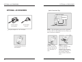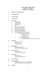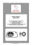
1
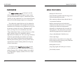
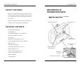
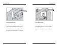
CONTENTS
OVERVIEW
2
MAIN FEATURES
3
SAFETY FEATURES
4
PACKAGE CONTENTS
5
DESCRIPTION OF TRANSMITTER PARTS
5
DESCRIPTION OF COLLAR PARTS
13
CHARGING THE RECEIVER/COLLAR
20
TESTING YOUR
PRIOR TO INSTALLATION
22
INSTALLATION
24
TROUBLESHOOTING
37
MAINTENANCE
39
OPTIONAL ACCESSORIES
40
WARRANTY AND REPAIR
INFORMATION
42
1
OVERVIEW
OVERVIEW
2
MAIN FEATURES
MAIN FEATURES
The
system gives you the
ability to allow your dog the freedom he wants, within
your specified boundaries. Dogtra’s containment system
contains your dog without the use of conventional fencing
that can be chewed through, jumped over or dug under.
Waterproof collar/receiver.
The width of the signal field can easily be adjusted at
the wall-mount transmitter. The strength of the electrical
stimulation can be adjusted on each separate receiver with
the intensity selection dial. In the Stimulation Only
mode, your dog will receive stimulation only. In the
Pager+Stimulation mode, your dog will receive a silent
pager/vibration, followed by stimulation when he
approaches the boundary area. Once your dog consistently
avoids the signal boundary, the stainless steel contact
points can be replaced with the plastic training probes.
With the plastic training probes, your dog will be able to
respond to the vibration warning without receiving any
electrical stimulation.
Intensity selection dial on each individual
collar/receiver that offers levels (1-5) to match
each dog’s personality and temperament.
Accessories for the
system
such as additional wire, flags, lightning/surge protector,
and the European 220-volt battery charger, are available
by calling Dogtra Company at (888) 811-9111 (8:30am4:00pm PST).
Long-range signal (will work up to 40 acres).
Pager/vibration signal that warns the dog prior to
electrical stimulation/correction.
Wire continuity indicator shows that the fence is
in operational condition.
Stimulation is discontinued after 8 seconds for
safety purposes. The collar will be reactivated
when the dog approaches the boundary again.
Easy to add additional Collar/Receivers.
2-hour rapid charge.
System turns to sleep mode to save energy and
power when your dog is playing safely within the
eF-3000 GOLD boundary.
Rechargeable receiver.
User-friendly controls.
3
PACKAGE CONTENTS
SAFETY FEATURES
Dogtra’s eF-3000 GOLD system collars use stateof-the-art microcomputer technology. The receiver
has an automatic control that limits the stimulus to
ten seconds.
Dogtra’s filtering system prevents reception from
outside sources other than your transmitter.
TRANSMITTER
DESCRIPTION OF
TRANSMITTER PARTS
transmitter
ON/OFF Indicator Light
Wire Indicator Light
PACKAGE CONTENTS
Wall-Mount Transmitter
Collar/Receiver
Transmitter Adaptor (25-volt 500mA)
Receiver Adaptor (5-volt 1A)
Test Lamp
Field Width
Adjustment Knob
Boundary Training Flags (50 ea.)
18ga Underground Fence Wire (500 feet)
Splices (4 ea.)
Wire Connectors for
Splicing
Ground Wire (green)
Transmitter Mount Screws (2 ea.)
Plastic Anchor (2 ea.)
ON/OFF & Function
Selection Switch
Plastic Training Probes (2 ea.)
Longer Contact Points (2 ea.)
Adaptor Jack
Connector
Owner’s Manual
Training Book
4
Connector for Ground Wire
5
TRANSMITTER
TRANSMITTER
Pager+Stimulation
Pager+Stim
OFF
OFF
Stimulation
Stimulation
Field Width Adjustment Knob
ON/OFF & Function Selection Switch
6
ON/OFF & Function Selection Switch
Field Width Adjustment Knob
ON/OFF & function selection switch has three
functions. When the toggle switch is in the up
position, the unit will give the dog a pager/vibration
followed by stimulation correction. When the toggle
switch is in the down position, only stimulation occurs
(without the pager warning). When the switch is in the
middle position, the power is off.
This knob controls the width of the signal field
(the distance from the boundary wire to the location
where the collar/receiver first activates). Turning the
knob clockwise increases the field width, giving
your dog a wider area before the activation begins.
Turning it counter-clockwise decreases the signal
field, thus giving the dog a shorter area prior to
activation.
7
TRANSMITTER
TRANSMITTER
Wire Indicator Light
ON/OFF Indicator Light
8
ON/OFF Indicator Light
Wire Indicator Light
When the ON/OFF & function selection switch
is either in the up or down position the ON/OFF
indicator light will be on, indicating that the power
is on. When the switch is in the middle position
the light goes off, indicating that the power is off.
When the wires are connected properly, the
wire indicator light will be on. In the event that
the eF-3000 GOLD wire becomes damaged or
disconnected the light will automatically turn off.
9
TRANSMITTER
TRANSMITTER
Adaptor Receptacle
Wire Connectors
Wire Connectors For Splicing
The easy-to-use push-release wire connectors let
you instantly connect or disconnect the boundary
wire leads. Wires should be stripped approximately
a half-inch before being inserted into the red
connectors on the bottom of the wall mount
transmitter. The
system
comes with a ground wire to protect the unit in the
event of lightning/power surge. Strip about a halfinch on each end of the ground wire and insert one
end into the black connector on the bottom of the
wall transmitter. The other end should be buried
into the ground or wrapped around a water pipe and
secured with electrical tape.
Adaptor Receptacle
Plug the 120-volt adaptor into a 120-volt wall
outlet and insert the adaptor plug into the adaptor
receptacle of the transmitter.
Option : A lightning/surge protector can be
purchased if there are no grounding options near the
wall transmitter.
10
11
TRANSMITTER
COLLAR
DESCRIPTION OF COLLAR PARTS
120-volt
Receiver
25V 500mA
Collar Strap
Wall-Mount Transmitter
Use the (2) included screws to mount the
transmitter to a wall securely near an outlet. The unit
will withstand freezing temperatures, but it is not
waterproof. Therefore, we recommend mounting the
transmitter in a safe, dry sheltered area such as a
shed, garage or carport. Plastic anchors have been
provided to secure mounting onto drywall. Use a 1/4
drill bit to make holes into the drywall. Insert the
anchors into the holes so that the open end faces out
and mount the transmitter by inserting the screws into
the open end of the anchors.
To power the wall transmitter, plug the AC daptor
into the standard 120-volt outlet and connect it to the
adaptor receptacle of the transmitter.
Battery Charging
Receptacle
Contact Points
Indicator Light
Intensity Selection Dial
12
13
COLLAR
Intensity Selection Dial
The stimulation level is adjustable from each
individual dog’s collar/receiver so that it is easy
accommodate each dog’s different personality and
temperament.
The stimulation levels range from level 1 to
level 5, level 1 being the lowest.
In order to select the proper intensity level for
each dog, we recommend that you begin at level 1
and continue to increase the level slowly until you
are able to notice a reaction from your dog.
This ensures that you select a level that is
appropriate for your dog.
When you place the knob at the OFF position,
the collar is completely shut off.
In order to maintain full use of the batteries in
the collar, please turn off the collar/receiver when
your eF-3000 Gold system is not being utilized.
14
COLLAR
Receiver Indicator Light (LED)
When first activating the eF-3000 Gold system,
the LED light on the collar/receiver will illuminate
for approximately 1 second to indicate that the
power is on. 2 seconds after the initial light, a blink
will occur every 2 seconds to indicate that the
collar/receiver is functioning properly.
(Green = full charge, Amber = medium charge,
Red = needs charge)
The color of the LED indicates the battery life of
the receiver.
When the collar does not receive a signal from the
transmitter for 10 seconds or more, the
collar/receiver will go into sleep mode, and the LED
light will stop blinking.
When your dog gets close to the wire boundary,
the indicator light will blink steadily to indicate that
a stimulation is being outputted depending on the
stimulation selection that you have chosen on the
wall-mount transmitter.
15
COLLAR
COLLAR
IMPROPER FIT
A loose fit can allow the collar to move around on
the dog’s neck. When this happens, the contact points
may rub the skin and cause irritation. If the collar is
too loose, electrical contact will be inconsistent and
your corrections will be inconsistent also.
Dogtra uses surgical stainless steel contact points
and Anti-microbial plastic to protect the dog’s skin.
ATTENTION!
PROPER FIT
The collar should be fitted so that the surgical
stainless steel contact points press firmly against the
dog’s skin. You should be able to fit a finger in
between the contact point and your dog’s skin. The
best location is either side of the dog’s windpipe.
16
Leaving the collar/receiver in the same location on
the dog’s neck, for an extended period of time can
cause skin irritation. If the dog is to wear the e-collar
for long periods, occasionally reposition the collar so
that the contact points are moved to a different
location on the dog’s neck. Make sure you check for
skin irritation, each time you use the unit.
17
COLLAR
COLLAR
Transmitter Adaptor
(25-Volt 500mA)
Receiver Adaptor
(5Volt 1A)
Collar/Receiver Battery Charging Receptacle
Adaptor
On the inside of the collar receiver, next to the
collar strap, is a battery charging receptacle with a
rubber plug.
The battery charger is designed for a 120-volt
wall outlet. (An European 220-volt AC charger is
also available.)
The unit will be fully waterproof with or
without the rubber plug. If the dog was in saltwater, be sure to rinse the receiver and
charging port woth clean water, and let air dry.
18
19
CHARGING THE RECEIVER/COLLAR
CHARGING THE RECEIVER/COLLAR
CHARGING THE RECEIVER/COLLAR
Battery Charging Procedure
Note : The unit has a partial charge when it leaves the
Dogtra facility, upon receipt of the collar, be
sure to give it a full 2-hour initial charge
before the first use.
1. Attach the charging cables to both the receiver as
shown on page.
2. Plug the charger into a 120-volt wall outlet.
When properly plugged in, all indicator lights
should glow red.
During the charging process, the unit will shut off.
Once the battery cable is unplugged from the unit
after a full charge, you will need to turn the unit on
again before use.
uses Lithium-Polymer batteries.
1. Charge the unit before using the unit for the first
time.
2. Do not charge the batteries near any flammable
substances.
3. Fully charge the batteries if the unit is to be stored
without use for a period of 3 months or more.
Recharge the unit if :
- The LED indicator light on the collar receiver is
emitting a red color.
- The indicator light on the receiver will not come on.
- The indicator light on the receiver comes on
momentarily, but will not stay on near the wire.
20
3. The Lithium-Polymer battery is fully charged
within 2 hours. The lights will stay red during the
charging process. The red light will change into a
steady green light when the battery is fully
charged. (When you disconnect the charger after
finishing the charge, you will need to restart the
units).
4. After charging, cover the battery charging
receptacles with the rubber plugs on the transmitter
and receiver.
NOTE : Only use Dogtra-approved batteries,
chargers, and accessories for the
When a charger is not in use, disconnect it from the
power source.
.
21
TESTING
TESTING YOUR
PRIOR TO INSTALLATION
TESTING
2. Unwind the length of ground wire that was
provided and strip about 1/2 inch off each end.
Insert one end of the ground wire into the first
wire connector jack and the other end into the
third, leaving the center jack free. If the wires are
connected properly, the wire indicator light will
be on.
3. Next, activate the collar/receiver by turning the
intensity level dial on the receiver to the desired
level. The LED light will blink once every two
seconds showing that it is on. If not activated for
10 seconds or more, the system will go into sleep
mode.
4. Hold the receiver in your hand with the contact
points facing up. Place the test lamp over the
contact points and approach the test loop.
1. To ensure that your
system is working properly, connect the
transmitter adaptor into the adaptor of the
transmitter and then plug the adaptor into a
household outlet. Switch the stimulation knob
to Pager+Stimulation, or Stimulation Only. The
ON/OFF indicator light should turn on.
22
5. Watch for the test light to come on and/or the
unit will emit the warning vibration if the unit is
in this mode at the wall mount transmitter.
Be careful not to touch the contact points as the
unit will emit stimulation when activated.
23
INSTALLATION
INSTALLATION
Fence Wire
INSTALLATION
Wire Placement
CAUTION - Before you install your fence wire,
contact the utility company to mark the utility lines
on your property before you begin digging. Be sure
to test your wire layout above ground before
permanent installation begins.
Carefully choose the areas in which you want to
contain your dog. A diagram may be helpful in
predicting unforeseen obstacles. (Please refer to the
diagrams below.)
The fence wire must make a continuous loop
around your property for your system to operate. The
signal is delivered from the terminal of the transmitter,
through the fence wire, back to the other terminal on
the transmitter. When this is accomplished, the wire
continuity light will emit a constant red indicator.
Front Boundary Only
Fence Front Yard Only
Front or Back Access
Basic Loop With Garden
Front Bounary With
Existing Fence
Keep wires-6ft. apart to avoid signal interference
24
25
INSTALLATION
INSTALLATION
IMPORTANT!
When creating a Front Boundary Only, Fence Front
Yard Only, or Front Boundary with Existing Fence
type of containment system. THE TWO PARALLEL
eF-3000 GOLD WIRES MUST BE 6-10 FEET
APART to avoid any signal interference.
Single loop systems must keep 6-10 feet of distance
between the wires as well.
Please note, the diagrams are not drawn to scale.
The
system includes
500 feet of boundary wire and 50 training flags.
Additional flags and wiring can be purchased through
the Dogtra Company. The estimated requirements are
as follows:
* For areas larger than 20 acres, please refer to our
web site at www.dogtra.com or call us at 888-811-9111.
26
27
ADDITIONAL PARTS
ADDITIONAL PARTS
ADDITIONAL PARTS
You will want to keep a signal field (area where the
dog will receive stimulation) at least 6-8 feet on
each side of the wire.
In addition, your dog will keep 2-4 feet away
from the signal field, so an overall signal field of
8-12 feet is preferred. Avoid making passageways
that are too narrow (i.e. along the sides on a house)
or your dog may hesitate from using them.
Tools
18 ga Underground Fence Wire (500 feet)
To install your
, you will
need a flat-edge spade, Phillips screwdriver and a
wire cutter/stripper. If your layout calls for the wires
to be connected across concrete, you will also need a
caulking gun, exterior silicon caulk and a circular
saw with a masonry blade for cutting the pavement.
Boundary Training Flags (50 ea)
The figures on p.25 are indicated for a
rectangular layout. Actual flag/wire requirements
may vary depending on the layout you’ve chosen.
28
29
ADDITIONAL PARTS
ADDITIONAL PARTS
Burying The Fence Wire
IMPORTANT : Before starting any digging,
contact your local phone, gas and power companies to
locate any other buried services. The
boundary wire does not have to be buried to operate.
For protective measures we highly recommend the
wire be buried about 3-4 inches underground.
Begin by digging a 4-inch deep cut where the wire
first enters the ground near the transmitter and
continue around the path of the loop wire. A 30- to 45degree angle cut made with a flat-edge spade will be
easiest to close. Try to keep the 2 wires from touching
as much as possible as this will enhance your signal.
Creating a Neutral Zone in the Boundary
Depending on your layout, you may want a neutral
zone where your dog can cross over the
without getting stimulation. Should your layout need
such an area, start by twisting the two pieces of fence
wire so they are braided (see diagram), from the
beginning of the neutral zone area to the end.
Braiding the two wires will interrupt the signal of the
buried fence, thus creating an area for your dog to
cross without getting stimulation.
To braid the fence wire, hold the two wires side by
side, and twist them around each other. This can also
be done by securing the two wire ends in the opening
of a drill and letting the drill twist the wires for you.
The tighter the wires are twisted, the better the signal
cancellation. A braid of approximately 16 twists per
foot is recommended.
30
Note : When covering a large area, a trenching
machine may be used to cut into the ground.
However, it is recommended that the wire be placed
in the trench by hand. A commercial wire-placing
machine may damage the wire.
IMPORTANT! Bury the fence wire after you
have tested the system and are sure it is working
properly. Do not nick or scrape the fence wire
during installation as it may result in an
intermittent signal or no signal.
Make gradual turns at the corners with a radius of
at least 3 feet. This will provide a more consistent
signal field that will avoid confusing the dog in these
areas.
31
ADDITIONAL PARTS
IMPORTANT!
DO NOT run fence wire within 6 feet parallel to
electrical, telephone, cable TV or other buried wire.
DO NOT run fence wire of one section within 10
feet of another section of fence wire or the signal may
cancel.
DO NOT run the fence within 10 feet of a
neighboring eF-3000 GOLD system’s boundary wire.
WIRE SPLICING
WIRE SPLICING
Driveways/Sidewalks
When crossing an asphalt driveway, make a 1/2-inch
deep cut across the driveway using a circular saw and
masonry blade. Close the crack with asphalt sealant
after the fence wire is placed in it. If an expansion joint
is available on driveway and sidewalks, place fence
wire in the joint and close it with outdoor caulk. When
crossing gravel, bury fence wire at least 3 inches deep.
PVC pipes or a garden hose can be used to protect the
wire. In water, anchor the wire with large rocks. Use
PVC piping or garden hose to protect the wire.
32
The wire connection must be waterproof
Do not use electrical tape, or soldered/twisted
wire nuts in this type of connection as it will cause
an intermittent signal or disarm the system. The
waterproof splices included in the
system are designed to provide a sealed connection
between the wires. The insulation on the boundary
wire should not be stripped before placing wire into
the holes. To use the waterproof splices, a single
boundary wire is placed into one of the three holes
of the splices. The other single boundary wire is
placed into one of the other holes. This should leave
one extra hole that is not used. A pair of pliers
should be used to gently press down on the top of
the blue part of the splice.
33
WIRE SPLICING
34
WIRE SPLICING
Connecting the Fence Wire to the Transmitter
The Signal Field
Splice the two ends of the twisted wire to each of
the two ends of the fence wire.
Drill a hole through the exterior wall or
window/door sill or run the fence wire through an
existing utility line hole. Connect the twisted fence
wire to the transmitter, either wire to either terminal
(wire ends must be stripped 1/2 -inch). A red
indicator light should appear indicating a continuous
fence wire field. If no light appears, check to make
sure that all fence wires are properly connected and
that the wire is not damaged.
The Field Width Adjustment Knob on the
transmitter controls the signal field width. Increasing
or decreasing the signal field width does not affect
the stimulation intensity.To test the signal field, walk
slowly toward the boundary wire holding the
collar/receiver at approximately the height of the
dog’s neck. Contact points must be upward with the
test light attached. Watch for the test lamp to
illuminate, this will give you an idea of the width of
the signal field. The wider the signal field is, the less
chance that the dog will run through the field and out
of your yard.The signal field should extend at least 6
feet on both sides of the wire (creating a field that is
12-feet wide total). An 8-12 foot field is preferred.
This will maximize the effectiveness of the
containment system and minimize the chances that
the dog will run through the signal field.
35
TROUBLESHOOTING
WIRE SPLICING
TROUBLESHOOTING
Note : If you alter the field adjustment knob by
turning it clockwise or counterclockwise, or by
removing it, you must check the signal field for the
desired setting.
When you are satisfied with the field width setting,
bury the fence wire below the grass and place the
flags at the distance where the test light comes on.
B. System Test Procedures:
Whenever you experience a malfunction, you will
need to do a test loop to determine which component collar, wall transmitter or yard wire - is not working.
Follow these steps to perform the test loop procedure.
Range in feet
20.0
16.0
OUTSIDE
12.0
A. Dog Doesn t Respond to Stimulus
- Adjust the collar fit.
- Trim the dog’s hair or use longer contact points
to make better skin contact.
- Recharge the battery in the collar receiver.
- Adjust the correction level.
8.0
1. Make a test fence using at least 10 feet of
fencing wire(or use the ground wire).
4.0
Feet 0.0
BOUNDARY WIRE
-4.0
-8.0
INSIDE
-12.0
3. Insert the two ends of the test fence wire into
the wall transmitter.
-16.0
-20.0
min
BLUE
GREEN
YELLOW
ORANGE
RED
Yellow
[ Field Width Adjustment Knob ]
36
2. Remove the existing boundary wire from your
wall transmitter.
Green
Orange
Blue
Red
4. Turn the field width adjustment knob to the
9 o clock position or a low setting.
37
TROUBLESHOOTING
5. Place the test light on the collar receiver. With
the collar receiver, approach the test loop and
note the distance between you and the wire when
the collar activates the test lamp.
6. Turn the field width adjustment knob to the
12 o clock position or a medium setting.
7. Back away from the wire and approach it again.
Determine the distance between you and the
wire when the collar activates. The distance
should be greater on the medium range setting.
If more than one collar receiver is used, repeat the
above test on each collar.
If there is no red light on the wire indicator light of
the wall transmitter with the test loop wire in place,
the wall transmitter is malfunctioning.
MAINTENANCE
General Maintenance Tips
Your system requires very little maintenance. The
collar/receiver for
sytem
is waterproof and activates even after being
immersed in water. To remove dirt, simply wipe
with soap and water.
The wall transmitter is not waterproof and must
be protected from the elements in a shed, garage or
carport.
Do not attempt to dismantle or repair any of
the system components : this will void the
manufacturer s warranty. These components
contain computerized circuitry that should be
serviced only by an authorized expert.
Caution
If the red light is solid on the wall transmitter, but
the collar does not activate on the test loop wire, the
collar/receiver is not working. Recharge the battery in
the collar/receiver and repeat the test.
38
Any changes or modifications of this device
which are not specifically approved by the party
responsible for compliance could void the user’s
authority to operate the equipment.
39
OPTIONAL ACCESSORIES
OPTIONAL ACCESSORIES
OPTIONAL ACCESSORIES
Quick Connection Tips
TRANSMITTER ADAPTOR
TRANSMITTER
Transmitter Adaptor
(25-Volt 500mA)
Receiver Adaptor
(5-Volt 1A)
European Adaptor for 220-volt outlets
Lightning/Surge Protecor
(PANAMAX)
40
FENCE WIRES
TRANSMITTER WIRES
STEP 1 Plug the lighting protector into a grounded
(3-wire) 120V AC outlet within five feet of where you
want to locate the transmitter
STEP 2 Cut the
fence wires near the
protector and strip all
four ends back 1/4
inch
STEP 3 Push the
connector tab firmly away
from yourself. The
connector jaws will open.
Push the stripped end of the
wire into the connector.
Repeat with the other three
wires.
41
WARRANTY AND REPAIR INFORMATION
WARRANTY AND
REPAIR INFORMATION
ONE-YEAR LIMITED WARRANTY
provides the original
purchaser a one-year limited warranty on parts and
labor from the date of the original purchase Products
covered include, Yapper Stoppers bark collars,
E-Fence 3000/3000Gold, Remote Release Systems,
(RRS, RRD and RRdeluxe) PL and QL Launcher
Systems.
Once the one-year warranty coverage expires, Labor
fees and shipping fees incurred are the customers’
responsibility. Labor fees will be variable depending
on the extent of work required.
To Qualify for the Limited Lifetime Warranty :
To register your Dogtra product, please log onto
our website at www.dogtra.com, click on the
warranty registration link and fill out the required
information. All registration must be completed
within 30 days of your purchase. If you do not have
access to a computer, you can call our toll free
number of 888-811-9111 so one of our customer
42
WARRANTY AND REPAIR INFORMATION
service representatives can register your product online
for you. Also if you were unable to register your
product on our website we will accept all products for
repair with a proof of purchase. We strongly recommend
you keep your original receipt. If your product is not
registered and proof of purchase is not available at the
time of service, Dogtra will estimate the age of the unit
by the serial number. Serial number estimates can be
different than the actual purchase time. Without proof of
purchase or product registration this is the only method
we have for determining the approximate date of
purchase.
Not Covered Under Warranty :
All units coming in for warranty or out of warranty
services, inbound shipping fees are the senders’
responsibility. Outbound shipping fees for out of
warranty units will be an addition to the repair fees and
are the customers’ responsibility.
If the product is resold, the warranty will become void
and all repairs will be subject to applicable labor fees.
Dogtra DOES NOT replace defective units or provide
refunds after 30 days from date of purchase.
43
WARRANTY AND REPAIR INFORMATION
Dogtra’s warranty DOES NOT cover repairs or
replacement due to misuse, improper maintenance or
lost units. Any water damage on models that are not
waterproof will not be covered. All replacement costs
for either the transmitter or receiver is the owner’s
responsibility.
The warranty is void if the unit has been altered or an
unauthorized person has attempted repair work.
Procedure for Repair Work :
The cost of shipping products under warranty
back to Dogtra is the customer’s responsibility.
Dogtra will provide/pay (via regular ground
service, within the continental United States) the
shipping cost back to the customer. Any expedited
shipping service will be at the customer’s
expense. Dogtra is not responsible for loss of
training time or inconvenience while the unit is in
for repair work. Dogtra does not provide loaner
units or any form of compensation during the
repair period.
44
WARRANTY AND REPAIR INFORMATION
A copy of the sales receipt showing the
purchase date is required before warranty work is
initiated.
Please include a brief explanation outlining the
problems and include your name, address,
city/state/zip code, daytime phone number,
evening phone number, and email address.
Or, you can visit our website at www.dogtra.com.
Click on the Service Request Form, print it out
and follow the instructions.
If repair costs are not covered under
warranty, we will call you for credit card
information once the work has been completed.
For any questions concerning your Dogtra
products call us Toll Free at 1-888-811-9111, M-F
8:30AM - 4:00PM, Pacific Time, or email us at
[email protected] for specific repair inquiries.
Send repair units to :
Dogtra Company / Repairs
22912 Lockness Avenue
Torrance, CA 90501
U.S.A.
45
MEMO
46
MEMO
47
MEMO
48