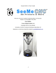
Download Motorized Z User Manual
Transcript
MOTORIZED Z SERIES PNEUMATIC INKER with SMALL DOT FEATURE INSTALLATION AND OPERATION MANUAL Models X4115/X4116 (EG), X4215/X4217 (KLA) 820-0096 Revision R November, 2013 X4115, X4116 Pneumatic IMPORTANT OPERATION NOTICE! The Model 350-0018 Motorized Z Pneumatic Controller is designed to operate at 80 5 PSI. FAILURE TO SET THE REGULATOR PROVIDING AIR TO THE CONTROLLER AT 80 PSI WILL RESULT IN INCONSISTENT SYSTEM OPERATION! Document 820-0096 Motorized-Z Inking System Installation and Operation Revision R, November, 2013 Service and Support Information Telephone: (707) 763-7799 OR (800) 767-9543 FAX: (707) 763-2631 Internet: www.xandexsemi.com Email: [email protected] 1360 Redwood Way, Suite A Petaluma, CA 94954 International Distributors China PREMTEK HOLDING CO. LTD. (Shanghai) 2F, No.1077 ZuChongZhi Rd Zhang Jiang Hi-Tech Park PuDong New Area Shanghai 201203 Peoples Republic of China Telephone: 86-21-50275859 Fax: 86-21-50275877 Contact: Jason Huang Email: [email protected] Web Site: www.premtek.com.tw Japan HUGLE ELECTRONICS, INC. 4-5-7 Iidabashi, Chiyoda-Ku Tokyo, Japan 102-0072 Telephone: (81) 3.3263.6661 Fax: (81) 3.3263.6668 Email: [email protected] Web Site: www.hugle.co.jp Korea HUGLE ELECTRONICS, INC. Br. Office: 2FL Hugle Bldg. 86-14 Garak-Dong, Songpa-Ku Seoul, Korea 138-803 Telephone: +82 (02) 431-7477 Fax: +82 (02) 449-6295 Email: [email protected] Taiwan PREMTEK INTERNATIONAL 4F, No. 47, Lane 2, Kuang-Fu Road Sec 2, Hsinchu City Taiwan R.O.C. Telephone: (886) 35.722000 Fax: (886) 35.725000 Email: [email protected] Web Site: www.premtek.com.tw 820-0096 IMPORTANT OPERATION INFORMATION! The Model 350-0018 Motorized Z Pneumatic Controller is designed to operate at 80 5 PSI. This setting is 10 PSI higher than the 70 PSI setting recommended for all other Xandex pneumatic controller units. FAILURE TO SET THE REGULATOR PROVIDING AIR TO THE CONTROLLER AT 80 PSI WILL RESULT IN INCONSISTENT SYSTEM OPERATION! LIFT KNOB TO UNLOCK, TURN KNOB TO ADJUST PRESSURE SETTING AND PUSH KNOB DOWN TO LOCK. SET AIR PRESSURE TO 80 PSI For more information contact Xandex Customer Service at (707) 763-7799 or Toll Free in the U.S at (800) 767-9543, FAX (707) 763-2631, or visit us on the Internet at www.xandexsemi.com 820-0096 This page is intentionally left blank. 820-0096 Table of Contents Section 1. Introduction............................................................................................ 1-1 Theory of Operation..................................................................................................... 1-1 Section 2. System Overview.................................................................................... 2-1 System Components..................................................................................................... 2-1 Set Part No. 340-4115/340-4116 ( X4115/X4116 EG) Set Part No. 340-4215/3404217 (X4215/X4217 KLA)...................................................................................... 2-1 Section 3. Installation .............................................................................................. 3-1 X4115/X4116 Inker Installation .................................................................................. 3-1 X4215/X4217 Motor Z Inker Assembly Installation................................................... 3-3 Controller Installation .................................................................................................. 3-5 Voltage Selection & Fuse Replacement ...................................................................... 3-8 Section 4. System Operation................................................................................... 4-1 Controller Operation .................................................................................................... 4-1 Programmable Thumbwheel Counter ...................................................................... 4-1 Ink Cartridge ................................................................................................................ 4-5 Cartridge Preparation ............................................................................................... 4-5 Cartridge Installation ............................................................................................... 4-6 Changing the Cartridge ............................................................................................ 4-7 Cartridge Priming..................................................................................................... 4-7 Cartridge Priming Tips ................................................................................................ 4-8 Tips to avoid common problems with DieMark Pneumatic Ink Cartridges. ........... 4-8 Ink Cartridge Labeling................................................................................................. 4-9 DieMark Cartridge Type Label............................................................................. 4-9 DieMark Cartridge Expiration Date Label ........................................................... 4-9 Cartridge Type Label Color Code.............................................................................. 4-10 Inker Assembly Setup & Alignment.......................................................................... 4-10 Motorized Z Small Dot Configuration....................................................................... 4-13 Section 5. Ink............................................................................................................ 5-1 General Information..................................................................................................... 5-1 Ink Curing .................................................................................................................... 5-2 Ink Removal Information............................................................................................. 5-3 DieMark Remover 8000 .......................................................................................... 5-3 Ink Removal Procedure........................................................................................... 5-3 Section 6. Maintenance & Troubleshooting.......................................................... 6-1 Ink Troubleshooting..................................................................................................... 6-1 Inker Troubleshooting.................................................................................................. 6-3 Shuttle Maintenance..................................................................................................... 6-5 Schedule and Preventive Maintenance Kits............................................................. 6-5 Maintenance Procedure............................................................................................ 6-5 Shuttle Removal (Reference Drawing 320-4215)................................................... 6-5 Shuttle Disassembly (Reference Drawing 216-0005)............................................. 6-6 Shuttle Inspection and Cleaning .............................................................................. 6-6 Shuttle Re-Assembly ............................................................................................... 6-6 Controller Maintenance ............................................................................................... 6-8 Controller Sequence of Operation ........................................................................... 6-8 Controller Diagnostics ............................................................................................. 6-9 Controller Troubleshooting........................................................................................ 6-11 820-0096 Internal Maintenance ................................................................................................. 6-13 Controller Logic Board Removal........................................................................... 6-13 Turn Audible Alarm ON/OFF ............................................................................... 6-13 Before returning the unit to service: ...................................................................... 6-14 Preventive Maintenance............................................................................................. 6-15 Pneumatic Controller Preventive Maintenance Schedule and Kits ....................... 6-15 Cartridge (V1) or Shuttle (V2) and Pressure (V3) Valve Replacement ................ 6-16 Controller Internal Regulator Adjustment ............................................................. 6-17 Section 7. System Specifications............................................................................. 7-1 Controller Specifications ............................................................................................. 7-1 Inker Specifications ..................................................................................................... 7-2 Stepper Motor Specifications / Part No.158-0010....................................................... 7-2 Ink Cartridge Specifications ........................................................................................ 7-3 Ink and Cartridge Availability ..................................................................................... 7-3 Inker Warranty ............................................................................................................. 7-4 Dot Size: Standard Mode in Mils................................................................................. 7-5 Dot Size: Standard Mode in Microns........................................................................... 7-6 Dot Size: Small Dot Mode in Mils .............................................................................. 7-7 Dot Size: Small Dot Mode in Microns ........................................................................ 7-8 System Drawings ......................................................................................................... 7-9 820-0096 Section 1. Introduction Theory of Operation The X4115/X4116, X4215/X4217 pneumatic Motorized Z inkers are designed for use as cabled in in-line and off-line inkers on Electroglas and KLA probers. The innovative motorized Z design combines operator friendly motorized Z movement capability, which provides fast, precise Z adjustment, with a dual air regulation system to provide the first dependable high speed small dot capability available in a pneumatic inker. The Motorized Z series inker also incorporates the convenience of DieMark cartridges with the reliability of a microprocessor controlled pneumatic dispensing system for the ultimate inking solution. Ink dots are deposited via pneumatic actuation of the inker shuttle mechanism and a simultaneous pulse of air into the cartridge reservoir. There is no filament and no direct contact with the wafer surface. A prober signal to the controller initiates the inking sequence, actuating the shuttle mechanism downward and sending an air pulse to the cartridge. As the shuttle extends to the downward position, the air pulse to the cartridge forces ink out of the cartridge barrel and forms a drop at the end of the needle tip. When the shuttle is at its lowest position, the drop makes contact with the wafer surface and forms a dot. After 25.2 milliseconds the shuttle returns to the normal position. After completion of each dot, a small amount of vacuum is developed in the cartridge by the closure of the valve, causing the ink to back up into the cartridge reservoir, preventing dripping. If another dot sequence is not initiated within 10 seconds, a “puff” pulse of air equal to 1/2 the dot setting duration (6.7 - 13 mS) will displace a small amount of ink back into the Teflon tube to aid in maintaining proper dot size after long delays between dots. The dot size is determined by cartridge air pulse duration. Adjust the controller setting to change the dot size - without changing the cartridge. Pneumatic cartridges are factory tuned, ensuring consistent dots and contain 40% more ink than standard DieMark cartridges. Thank you for selecting Xandex as your inking choice. Please spend a few minutes familiarizing yourself with the unit. Most questions you may have will be answered in this manual. If you would like further assistance, please contact your local Xandex distributor or call us at (707) 763-7799 or Toll Free in the U.S: (800) 767-9543. FAX (707) 763-2631. For more information about Xandex and our complete line of quality inking and interfacing products, visit us on the Internet at www.xandexsemi.com or email: us at [email protected]. 820-0096 1-1 Theory of Operation Introduction This page is intentionally left blank. 1-2 820-0096 Section 2. System Overview System Components Set Part No. 340-4115/340-4116 ( X4115/X4116 EG) Set Part No. 340-4215/340-4217 (X4215/X4217 KLA) 1. Regulator Assembly Part No. 220-0076 2. Cable/Connector Assembly Type AC - Part No. 210-0109 (X4115/X4116) Type CC - Part No. 210-0110 (X4215/X4217) 3. Air Hose Regulator > Controller Part No. 210-2001 4. A. AC Power Cord (USA)* Part No. 158-0051 C B. AC Power Cord (UK)* Part No. 158-0408 C. AC Power Cord (Europe)* Part No. 158-0407 5. Motorized Z Pneumatic Controller (Includes AC Power Cord) Part No. 350-0018 *One (1) Power Cord, specified at time of ordering, is included with each set. 6. Pneumatic Inker Assembly Part No. 320-4215 (All Models) A. Inker Base Part No. 220-0031 (All Models) A B B. Pneumatic Shuttle Part No. 216-0005 C. 7 Pin Plug, Stepper Motor Part No. 158-0008 7. Inker Mounting Plate Part No. 120-0019 (X4215/ A B C X4217) 820-0096 2-1 System Components System Overview This page is intentionally left blank. 2-2 820-0096 Section 3. Installation X4115/X4116 Inker Installation The X4115/ X4116 pneumatic inker installs directly onto the insert ring on an Electroglas model 10XX, 20XX or 40X0 series prober. The X 4115/X 4116 inker sets are identical except for pneumatic controller software. The X4116 inker set for EG probers comes with a pneumatic controller that incorporates the "Half-Puff" software option (X4115 = Standard Motor-Z controller). 1. If you are currently using another inker, remove it from the prober. CAUTION: Move the chuck/wafer from underneath the inker when installing inker to prevent damage. 2. Lift the inker swing arm to the up position. The mounting holes in the inker base will now be visible. X4115 INKER ASSEMBLY WITH SWING ARM IN UP POSITION (2X) 4-40 x 3/8 INSTALLATION SCREW 3. Install inker using two (2) 4-40 x 3/8 screws (supplied) into existing mounting holes on the prober insert ring. 4. Proceed to the “Controller Installation” portion of this Installation Section (3), and install the pneumatic controller per instructions for your application. 820-0096 3-1 X4115/X4116 Inker Installation Installation 5. With the controller and inker installed, connect the fitting on the controller-toshuttle air hose into the pneumatic connection on the rear of the pneumatic controller labeled "SHUTTLE". 6. Plug the jack from the inker stepper motor into the mating jack on the rear of the controller labeled "MOTOR". 7. Proceed to Section 4 “System Operation” for ink cartridge installation, inker setup, alignment and controller operation instructions. CAUTION: After an ink cartridge is installed, the inker arm should NOT be lowered back into operating position with the Z height adjusted completely down. The cartridge may be positioned too low, and the Teflon tube in the cartridge needle will smash into the wafer when the arm is lowered. This will stop the ink flow and possibly ruin the cartridge or damage the wafer! Z ADJUST MOTOR ASSEMBLY CONTROLLER-TO-SHUTTLE AIR HOSE CARTRIDGE FITTING (RED HOSE) X/Y ADJUSTMENT JOYSTICK X/Y POSITION LOCK DM-2 PNEUMATIC INK CARTRIDGE INKER BASE ASSEMBLY STEPPER MOTOR CABLE CONNECTOR TO CONTROLLER PNEUMATIC SHUTTLE ASSEMBLY WAFER SURFACE 3-2 820-0096 Installation X4215/X4217 Motor Z Inker Assembly Installation X4215/X4217 Motor Z Inker Assembly Installation The X4215/X4217 pneumatic inker is for use with KLA 1007, 1011, 1200 and 1220 model probers. The X4215/X4217 installs directly onto the head plate of a KLA/TEL prober, using a mounting plate (P/N 120-0019, supplied). The X 4215/X 4217 inker sets are identical except for pneumatic controller software. The X4217 inker set for KLA probers comes with a pneumatic controller that incorporates the "Half-Puff" software option (X4215 = Standard Motor-Z controller). 1. If you are currently using another inker, remove it from the prober. CAUTION: Move the chuck/wafer from underneath the inker when installing inker to prevent damage. 2. Align the mounting plate (P/N 120-0019) over the existing inker mounting holes on the prober. 3. Install the mounting plate using two M3 X 0.5 X 6mm screws ((P/N 5109201 supplied). 4. Lift the inker swing arm into the up position. The inker base mounting screws should now be accessible. 5. Install the inker base onto the mounting plate using (2) 4-40 x 1/4 screws (P/N 510-3104). X4215 INKER ASSEMBLY WITH SWING ARM IN UP POSITION INKER BASE (2X) 4-40 X 1/4 SCREWS MOUNTING PLATE P/N 120-0019 (2X) M3 X 0.5 X 6mm SCREWS MOUNTING SURFACE 820-0096 3-3 X4215/X4217 Motor Z Inker Assembly Installation Installation 6. Proceed to the “Controller Installation” portion of this Installation Section (3), and install the pneumatic controller per instructions for your application. 7. With the controller installed, connect the fitting on the controller-to-shuttle air hose into the pneumatic connection on the rear of the pneumatic controller labeled "SHUTTLE". 8. Plug the jack from the inker stepper motor into the mating jack on the rear of the controller labeled "MOTOR". 9. Proceed to Section 4 “System Operation” for ink cartridge installation, inker setup, alignment and controller operation instructions. CAUTION: After an ink cartridge is installed, the inker arm should NOT be lowered back into operating position with the Z height adjusted completely down. The cartridge may be positioned too low, resulting in the Teflon tube in the cartridge needle smashing into the wafer when the arm is lowered. This will stop the ink flow and possibly ruin the cartridge or damage the wafer! Z ADJUST MOTOR ASSEMBLY CONTROLLER-TO-SHUTTLE AIR HOSE CARTRIDGE FITTING (RED HOSE) X/Y ADJUSTMENT JOYSTICK X/Y POSITION LOCK DM-2 PNEUMATIC INK CARTRIDGE INKER BASE ASSEMBLY PNEUMATIC SHUTTLE ASSEMBLY MOUNTING PLATE P/N 120-0019 STEPPER MOTOR CABLE CONNECTOR TO CONTROLLER WAFER SURFACE 3-4 820-0096 Installation Controller Installation Controller Installation Note: The Model 350-0018 Motorized Z controller is designed to operate at 80 5 PSI. This is 10 PSI higher than the 70 PSI setting recommended for all other Xandex pneumatic controllers. FAILURE TO SET THE REGULATOR PROVIDING AIR INPUT TO THE CONTROLLER AT 80 PSI WILL RESULT IN INCONSISTENT SYSTEM PERFORMANCE! 1. Remove the bracket from the regulator/filter assembly by removing the plastic retaining nut. Mount the regulator/filter bracket in a convenient location (mounting screws are not supplied). The regulator can be mounted to the bracket with the supplied nut after the bracket is installed. LIFT KNOB TO UNLOCK, TURN KNOB TO ADJUST PRESSURE SETTING AND PUSH KNOB DOWN TO LOCK. MOUNTING BRACKET AIR FLOW ARROW PLASTIC NUT RETAINS BRACKET LOCATED ON ONE SIDE ONLY (BEHIND GAUGE) INSTALL REGULATOR - TOCONTROLLER AIR HOSE HERE (P/N 210-2001) REGULATOR/FILTER ASSEMBLY P/N 220-0076 2. Install 1/4 O.D. x 0.170 I.D. polyethylene tubing (not supplied) to the main air source and then connect to the input fitting on the regulator. (The left side when facing the gauge.) 3. Connect the regulator-to-pneumatic controller air hose (P/N 210-2001 supplied) to the output fitting on the regulator. (The right side when facing the gauge.) 820-0096 3-5 Controller Installation Installation Note: The regulator-to-pneumatic controller air hose supplied by Xandex, is 6 feet long. If the distance (hose length) requirement exceeds this length, use 1/4 O.D. x 0.170 I.D. polyethylene tubing. 4. Plug the regulator-to-controller air hose into the small air connection on the rear of controller. Note: The air hose connectors are spring locked. If the air hose connectors do not insert easily, make sure the spring lock is in the open position by pushing the metal snap-lock down until it clicks. 5. Turn on the main air and adjust the regulator until it reads 80 5 PSI on the dial. To make regulator adjustments, pull up on the knob on the top of the regulator to unlock, then rotate the knob clockwise to increase or counterclockwise to decrease. Push down on the knob after adjustment to lock it into position. 6. Check all connections for air leaks. If required, turn off the main air and make necessary repairs. 7. Install the cable/connector (P/N 210-0109 or 210-0110) to the inker port on the prober and the "PROBER" connector on the rear of the controller unit. 8. Move the toggle switch on front of the controller to "RUN" (mid ) position. 9. The controller is factory set at 120 VAC @ 50-60 Hz. If your AC input voltage is different than 120V, follow the instructions in this Section (3) “Voltage Selection and Fuse Replacement” to change the controller to your requirement. 10. Install the AC power cord into the back of the controller. Plug the power cord into an AC supply outlet. At this point, the "INK ON" LED will flash once, while the "STATUS" LED will stay on. Proceed to Section 4 “System Operation” for ink cartridge installation, inker setup, alignment and controller operation instructions. 3-6 820-0096 Installation CONNECT CONTROLLER -TO-SHUTTLE AIR HOSE HERE CONNECT REGULATOR-TOCONTROLLER AIR HOSE HERE CONNECT SUPPLIED AC POWER CORD HERE Controller Installation CONNECT MOTOR CABLE CONNECTOR HERE CONTROLLER SERIAL NUMBER CONNECT CABLE/ CONNECT ASSEMBLY P/N 210-0109 (X4115/X4116) P/N 210-0110 (X4215/X4217) HERE FOR USE WITH OPTIONAL FOOT SWITCH P/N 350-0010 FUSE ACCESS / VOLTAGE SELECTION DOOR 820-0096 3-7 Voltage Selection & Fuse Replacement Installation Voltage Selection & Fuse Replacement Note: This unit is shipped with the voltage set for 120VAC. Two fuse types are included, one for 100/120VAC and one for 220/240VAC, however, the controller unit is shipped without a fuse installed. Select the correct fuse for your voltage rating from the chart below and install per instructions. Discard unused fuse. 1. Disconnect power cord from rear of controller (if connected). Note: There is no power switch on this unit. If the unit loses power, memory of any hour or dot count programmed into the unit will be lost. 2. Swing open the fuse cover door by lifting on tab on the right side of the door. (A small screwdriver may be necessary.) ROTATE THUMB WHEEL UNTIL CORRECT VOLTAGE SHOWS THROUGH SLOT IN DOOR TOP SLOT NOT USED FUSE HOLDER INSTALL WITH ARROW DOWN IN LOWER SLOT SWING DOOR OPEN SNAP CORRECT FUSE INTO HOLDER 3. To change voltage setting, rotate the thumbwheel until correct voltage listed on the thumbwheel is facing out (visible through the slot in the door when the door is closed.) 4. To change the fuse, remove the fuse holder from the module by pulling is straight out. Carefully pry the fuse from the holder and replace (see fuse rating chart below.) 5. Insert the fuse holder into the bottom (lower) slot in the module with the arrow on the fuse holder pointed down. 6. CAREFULLY close fuse cover door. Verify that the correct voltage shows through the window on the module door. Reconnect power cord and verify controller power. INPUT VOLTAGE AT 50-60HZ 100/120VAC 220/240VAC 3-8 FUSE RATING; 250 V 0.75A 0.375A FUSE TYPE: T or Time Delay 3AG (0.25” x 1.25”) 3AG (0.25” x 1.25”) XANDEX PART NUMBER 158-0032 158-0479 820-0096 Section 4. System Operation Controller Operation Programmable Thumbwheel Counter Individual thumbwheel settings are available to monitor the number of DISABLE Dots placed by an ink cartridge (Dots X 1000). These three thumbwheels can be set to any number of dots between 1 and 999,000. A red "STATUS" LED will be illuminated and an audible alarm will sound when the programmed limit is exceeded. For example, if you select 30,000 dots (turning the "DOTS X 1000" thumbwheel to 30) the "STATUS" LED will light when 30,000 dots have been deposited. Upon installation of a new ink cartridge, it is recommended that the thumbwheels be reset to alert the operator when a cartridge is nearing replacement. The Dots X 1000 setting is programmed by using the RESET button. Reset Button: A "RESET" button is located to the right of the thumbwheels DISABLE for resetting the counters in the microprocessor. When the "RESET" button is depressed once, the "INK ON" LED will flash for 5 seconds. If it is pressed a second time within 5 seconds, it will "read" the setting on the Dots X 1000 thumbwheel switches and load those values into the microprocessor. If the "RESET" button is not pressed a second time and the 5-second flash time is exceeded, the "INK ON" LED will stop flashing and the current set points and internal counts will not be changed. Note: If the prober is running and the "RESET" button is pushed, the "INK ON" LED will flash intermittently. After 5 seconds, the "INK ON" LED will stop flashing and the unit will continue with the current programming. If the prober is running and the "RESET" button is depressed a second time within the 5 second reset time, INPUT SIGNALS FROM THE PROBER WILL BE INHIBITED AND THE UNIT WILL RESET AND RE-PROGRAM ITSELF. The "RESET" button is also used to enter the diagnostic mode when power is applied to the controller with the "RESET" button depressed. For details and descriptions of controller diagnostic tests see “Controller Diagnostics” in Section 6. 820-0096 4-1 Controller Operation System Operation Dot Counter: A separate LCD dot counter is located on the front panel DISABLE above the thumbwheels. This counter has an internal Lithium battery with a nominal life of 10 years, and an integral reset button. Pressing the small red reset button next to the LCD window will reset the counter display only. It will have no effect on the counter circuits within the microprocessor. Upon installation of a new ink cartridge, it is recommended that the counter be reset to accurately record the numbers of dots produced by that cartridge. Audible Alarm: An audible alarm is activated, along with the "STATUS" LED, whenever the "DOTS X 1000" thumbwheel setting has been reached. The alarm is silenced and reset by pausing the prober, resetting the "DOTS X 1000" thumbwheels if desired and depressing the "RESET" button twice within five seconds. The audio alarm may be disabled by means of an internal jumper on the controller PCA. See Section 6 “Maintenance and Troubleshooting” “Controller Internal Maintenance” for detailed instructions. DISABLE Dot Size Thumbwheels: The adjustable Dot Size Thumbwheels on the front panel are used to vary the size of the dot produced without affecting set-up or requiring additional operator steps. The microprocessor reads the thumbwheel settings and outputs a signal to enable the associated air valve for a predetermined amount of time. Higher settings enable the cartridge air valve for a longer time, producing a larger dot. Depending on the type of ink cartridge (A5, A6, or A8) and ink used (Markem 6990, 6993, 6997 or Xandex 8103, 8104 7824 or 7824T), a 14 mil to 50 mil dot is possible. It is recommended that the proper dot size for the die be selected to maximize cartridge usage and minimize problems with too large or too small dots. Refer to Section 7 for dot size specification tables. 4-2 820-0096 System Operation Controller Operation Mode Selection Switches: There are two mode selection mode switches located on the front panel for selecting different inker operating modes. The following is a description of the functions of each switch position. DISABLE Top Mode Switch Positions SETUP = Shuttle air valve enabled for coarse Z height setup RUN = Normal Operation DISABLE = Shuttle air valve disabled (troubleshooting aid) When placed in the SET-UP position, the shuttle air valve (V2) is enabled, moving the shuttle to the lower position for Z set-up adjustment. While in the SET-UP mode, perform coarse Z height adjustment as detailed in the Set-Up and Alignment procedure. After five minutes in the SET-UP mode, the microprocessor will disable the shuttle air valve, returning the shuttle to the normal position. If set-up was not completed, return the switch to the RUN position, then back to SET-UP. In the RUN position, the system operates normally. The switch is placed in the RUN position for inking. When the toggle switch is placed in the DISABLE position, the shuttle air valve (V2) is disabled and the shuttle does not extend during inking. This mode is used in controller diagnostics, to place dots in hand-inking applications with the optional foot switch or when utilizing the prober Z function without actuating the shuttle. DISABLE Bottom Mode Switch Positions LARGE DOT = Controller operates at external regulator pressure SMALL DOT = Cartridge valve operates at internal regulator pressure Dot size is determined by the cartridge type (A5, A6 or A8), ink viscosity, air pressure supplied to the cartridge valve and the dot size thumbwheel setting, which regulates the duration of the air pulse to the cartridge. When the bottom switch is placed in LARGE DOT position, the controller operates at the air pressure setting of the external regulator (80 psi nominal). Average large dot size parameters for the three available cartridge types with different ink varieties in dot size thumbwheel increments of 5, are included in Section 7 . When the bottom switch is placed in SMALL DOT position, the controller operates the cartridge valve (V1) at an air pressure determined by a second, internal regulator, which is factory set at 10 psi. This regulator is not operator adjustable, but may be reset if necessary to optimize small dot production. See “Small Dot Configuration” later in this section (4) for detailed instructions on small dot mode. 820-0096 4-3 Controller Operation System Operation Bottom Mode Selection Switches (cont’d): Dot Size Thumbwheels, Dot Counter and Motorized Z UP and Z DOWN buttons do not change function in SMALL DOT mode. Small dot production requires the use of the A5 cartridge type. Typical small dot size parameters for the A5 cartridge with available ink types are included in Chapter 7. For more information on the small dot capabilities of the motorized Z controller, see “Motorized Z Small Dot Configuration” later in this section (4). Z UP and Z DOWN Buttons: Z UP and Z DOWN buttons allow motorized adjustment of the inker Z height in 0.0005 (.5mil) increments each time either button is DISABLE depressed. The buttons should be pressed no faster than one time per second as the unit cannot react to faster use and such use will result in zero movement. This fast, precise method of setting inker Z height simplifies operator/inker interface and shortens initial setup time. Minor adjustment of Z height may also be necessary after changing an ink cartridge, due to slight manufacturing variations between cartridges. The Z UP and Z DOWN buttons can be used to quickly move the inker up or down by depressing and holding down either button. This function is useful to quickly raise inker Z height when changing cartridges, but great care should be taken not to “run” the inker down into the wafer in this mode. Note: The specifications for the bipolar stepper motor installed on the Motorized Z inkers are listed in Section 7. The manufacturer’s specification of 0.001 linear movement per step is correct. The motor is driven in ½ steps to achieve 0.0005 linear movement per activation. External Switch Input: There is a second input on the rear of the unit for use with a foot switch. Upon activation, the foot switch sends a > 50mSec switch closure signal (across pins 1&3) to the controller, enabling an inking sequence. There is a 50millisecond delay between the end of the sequence and the recognition of the next switch closure. No other adjustments or settings need to be made. This input is not used with the X4000 Series inkers. 4-4 820-0096 System Operation Ink Cartridge Ink Cartridge CAP INTERNAL MEMBRANE CARTRIDGE NECK NEEDLE COLLAR The ink cartridge used with the X4000 Series Inkers is a DM-2, available in A5, A6, and A8 types (designating 0.005, 0.006, and 0.008 Teflon tube I.D., respectively). DM-2 cartridges have a polypropylene reservoir (sealed at the bottom by a thin membrane) and a small Teflon tube encased in a stainless steel needle. When the cartridge is opened, the needle punctures the membrane to provide ink flow through the Teflon tube. Each cartridge holds 1.0 grams minimum of ink and can produce a wide range of dot sizes. Dot size is controlled by changing the duration of the air pulse into the cartridge reservoir, which determines how much ink is forced through the Teflon tube to create the ink drop at the needle tip. A5 and A6 cartridge types will produce an average of 30,000 dots*, while the A8 averages 10,000 dots*. For more information see Section 5 “Ink” and “Ink Cartridge Specifications” in Section 7 “System Specifications.” * Averages exclude 8104 ink type. Dot production figures are averages and as such, are not guaranteed. Testing is performed at ambient temperature of 70 degrees F, relative humidity of 50% on polished, unetched silicon wafers (no passivation) and based on pneumatic controller operating at "MIDDLE" dot size setting (standard controller = dot size knob centered between "MIN" and "MAX": Auto-Z/Motor-Z Controller = dot size thumbwheel setting of 50). Dot production figures represent an average of results for multiple ink types. Your yield may be higher or lower depending on the ink type and dot size setting you use. Average figures are based on complete cartridge use within cartridge open shelf life periods (5 days maximum or 3 days maximum) as stated for each specific ink type. Cartridge Preparation 1. Place the cartridge into the cartridge preparation tool (Xandex Part No. 200-0001) as shown, exercising care to avoid damaging the Teflon tip. The cartridge cap should be seated in the tool hinge with the needle resting in the slot. 2. Firmly squeeze the tool fully closed with a smooth, quick motion. This will push the cartridge body forward, causing the needle to puncture the internal membrane. NEEDLE PUNCTURES MEMBRANE NEEDLE COLLAR FLUSH WITH NECK 3. Open tool and remove cartridge. The needle should be straight and the needle collar flush with the cartridge neck. 820-0096 4-5 Ink Cartridge System Operation CAUTION: Do not shake the cartridge at any time, as air bubbles may be introduced into the reservoir and restrict the flow of ink. If mixing of the ink in the reservoir is desired, roll the cartridge between thumb and forefinger (or between palms) for 1-2 minutes prior to installation. Cartridge Installation CAUTION: Move the inker arm to the UP position when installing or changing cartridges to prevent damaging the cartridge tip. 1. Use the slotted section of the cartridge preparation tool and a counter-clockwise motion to remove cap. 2. Thread the cartridge onto the brass air fitting of the RED AIR HOSE, turning the cartridge clockwise until snug. 3. Press top of cartridge into shuttle spring clip. 4. Press cartridge body into shuttle forks until the neck fully snaps into place. Cartridge is now ready for priming. (See “Cartridge Priming" later in this Section (4) for instructions) 4-6 820-0096 System Operation Ink Cartridge Changing the Cartridge 1. Lift the inker swing arm to the UP position. 2. Place thumb and forefinger on each side of the cartridge and gently pull up to remove cartridge. 3. Unthread the cartridge from the air fitting and discard in the proper manner. 4. Inspect the air fitting and air hose for ink contamination and clean or replace as necessary. 5. Install a new cartridge per installation instructions. Cartridge Priming CAUTION: Always wear protective eyeglasses when handling an active pneumatic inking system! 1. Prepare a cartridge per the “Cartridge Preparation” section of this manual. 2. Install a cartridge to the inker per the “Cartridge Installation” section of this manual. 3. Lift the inker swing arm to the UP position. Note: Cartridge priming is done with the inker arm in the UP position. 4. Move the controller switch to “RUN”. 5. Push the “RESET” button on the controller for at least 3 seconds and hold down until ink appears at the needle tip. Note: When the”RESET” button is initially pushed the “INK ON” LED will begin to flash. At the end of 3 seconds the “INK ON” LED will light continuously and the air valve will begin to pulse, priming the cartridge. 6. Once priming is completed, clean excess ink from the needle tip with a lint free cloth. Cartridge is now ready for operation. Proceed to “Inker Assembly Setup and Alignment” in this section (4) to prepare the inker. Note: Always use the RESET button to pulse the cartridge valve when priming a cartridge with the inker swing arm in the up position. The RESET button fires only the inker's cartridge valve. If the shuttle valve is fired with the swing arm in the up position, (by using the prober's test inker function for example) ink may be forced into the cartridge air fitting and air hose, contaminating both. 820-0096 4-7 Cartridge Priming Tips System Operation Cartridge Priming Tips Tips to avoid common problems with DieMark Pneumatic Ink Cartridges. DO NOT attempt to refill Xandex DieMark Ink Cartridges. Cartridges are disposable and designed for single use only. Using a refilled cartridge will have an adverse effect on functionality and performance. Please note, Xandex does not warranty refilled cartridges. Handling Tips: Handle cartridges with care to avoid damaging the exposed Teflon tube at the tip of the needle When removing the cartridges from the clamshell package, lift the cartridge straight up to avoid bending the needle or damaging the Teflon tube. Allow the cartridge to reach optimal temperature of 18-25C (65-78F) before priming the cartridge. Never attempt to prime and use cartridges that are not at optimal temperature. Priming Tips: Wipe off any excess ink on the outside of the needle using a lint free cloth or swab before use. DO NOT use the cartridges beyond the recommended open time for the ink type in the cartridge. Recommended open time is three (3) days for 7824, 7824T, 8103 and 8104 and five (5) days for 6990, 6993, and 6997. 4-8 820-0096 System Operation Ink Cartridge Labeling Ink Cartridge Labeling DieMark ink cartridges are individually labeled with two distinct labels. One label shows the cartridge type and the other label indicates the ink batch number, ink type and expiration date of the cartridge. Do not remove the labels from the cartridges as this can cause cartridge type and ink types to be confused at cartridge installation, resulting in improper performance. Removal of cartridge labels will also void the cartridge warranty. DieMark Cartridge Type Label This label contains the cartridge type, (either A5, A6 or A8). DieMark TM CARTRIDGE LABEL WITH CARTRIDGE TYPE TYPE A5 DieMark Cartridge Expiration Date Label This label indicates the ink type and batch number of the ink contained in the cartridge and the cartridge expiration date. Expiration dates shown are for unopened cartridges. Markem 6990, 6993, 6997 and Xandex 8103, 8104 = Four (4) months. Xandex 7824 and 7824T = Four (4) months. After the cartridge is opened, consistent ink flow can only be expected for up to five (5) days for Markem 6990, 6993, 6997 and three (3) days for Xandex 7824, 7824T, 8103 and 8104. GF9801-302 EXP. OCT.01.01 8103 820-0096 INK BATCH NUMBER EXPIRATION DATE (MONTH, DAY & YEAR) I.E.: OCTOBER 01, 2001 INK TYPE 4-9 Cartridge Type Label Color Code System Operation Cartridge Type Label Color Code DM‐2 & DM‐2.3 PNEUMATIC CARTRIDGE LABELS NEW LABEL DESCRIPTION A5 = RED A6 = BLUE A8 = YELLOW Inker Assembly Setup & Alignment 1. Prepare, install and prime an ink cartridge per the instructions in this section (4). 2. Once priming is completed, verify that the inker is at maximum Z height adjustment, set the top mode switch to "RUN", then lower the inker arm and snap into place. 3. Position the chuck/wafer under the inker and set the prober chuck “Z Up”. CAUTION: If the inker height is adjusted with the forcer stage "Z Down" the cartridge will be positioned too low and the cartridge needle will smash into the wafer when you begin inking. This will stop the ink flow and possibly ruin the cartridge or damage the wafer! 4. Move the top mode switch to "SETUP". The shuttle will extend to its lowest position. Create a droplet of ink at the needle tip by pressing the prober "TEST INKER" button twice. Note: The Controller can remain in the "SETUP" mode for a maximum of 5 minutes. After 5 minutes, the Controller will disable the shuttle air valve, returning the shuttle to normal position (the inker will fire, but the shuttle will not move) preventing damage to the valve caused by extended operation. If this happens, move the toggle switch to "RUN" then back to "SETUP" to complete alignment. 4-10 820-0096 System Operation Inker Assembly Setup & Alignment 5. Loosen the X-Y lockdown knob on the inker sufficiently to allow X-Y movement of the cartridge tip when the joystick is manipulated. The X-Y lockdown knob should be tightened to give spring tension to the joystick at all times to maintain X-Y position. Use the joystick to adjust the X-Y position of the cartridge tip to the center of the die. 6. Press the Z DOWN button once per second to lower the shuttle until the ink droplet at the needle tip touches the wafer surface. The Teflon tube will be 12 mil from the wafer surface. CAUTION: Extreme care should be taken when using the "Z UP" and "Z DOWN" buttons. The buttons should be pressed no faster than one time per second. The switch cannot react to faster use and such use will result in zero movement. Pressing and holding down either of the "Z UP" or "Z DOWN" buttons will cause the motor to "RUN", moving the inker rapidly up or down. The "Z UP" and "Z DOWN" buttons should be used in this manner only when it becomes necessary to quickly move the mechanism up or down a considerable distance (i.e., cartridge replacement). 820-0096 4-11 Inker Assembly Setup & Alignment TEFLON TUBE System Operation CARTRIDGE NEEDLE WAFER SURFACE NO ! Tube too close to wafer NO! Tube too far away from wafer YES! Ink drop is deposited on wafer surface CAUTION: Do not let the Teflon cartridge tube contact the wafer surface. This may crush the tip preventing ink flow and damaging the cartridge! 7. Set the top mode switch to "RUN" to retract the shuttle. Index and test fire the inker a few times and check the dots for size and roundness. Each time the inker fires, the "INK ON" LED flashes. 8. Using the "DOT SIZE" thumbwheels, change the setting until the desired dot size is achieved (see the tables in Section 7). If you have problems, refer to “Inker Troubleshooting” in Section 6 “Maintenance & Troubleshooting” of this manual. It is recommended that during initial setup, several rows of dots be placed and inspected for consistency. If skipped dots are detected, lower inker Z height until consistent dots are achieved. Note: Due to the unavoidable incidence of slight manufacturing variations from cartridge to cartridge, additional Z height adjustment of the inker may be necessary after changing cartridges. 9. If the dots are round and of proper size, basic installation is complete. 10. If adjustment is required, use the Z UP and Z DOWN buttons on the front of the controller to make the final adjustments until round dots are achieved. Pressing either the Z UP or Z DOWN button results in a movement of approximately 0.0005 inches up or down for each time pressed. The "INK ON" LED will flash each time either button is pressed (only when the unit is not placing dots (inking). 11. If the unit fails to operate as specified, please contact Xandex Customer Service for assistance at (707) 763-7799 or toll free in the United States at (800) 767-9543. 4-12 820-0096 System Operation Motorized Z Small Dot Configuration Motorized Z Small Dot Configuration When the mode switch on the front of the controller is switched to SMALL DOT, the air supplied to the cartridge valve, (V1) is routed through a second, internal regulator, which reduces the air pressure sent to the cartridge. This regulator is not operator adjustable but may be internally reset to optimize controller small dot performance. See “Controller Internal Regulator Adjustment” in Section 6 “Maintenance and Troubleshooting”. Small dot production with the Motorized Z pneumatic inking system requires use of the A5 cartridge type. Tables are provided in Section 7 that show average dot size results for different ink types in thumbwheel setting increments of 5. These tables indicate average results from testing preformed on unetched wafers with no passivation and are intended for use as guidelines only. All controller functions, UP and DOWN buttons, LED dot counter, programmable dot counter and dot size thumbwheels, SETUP, RUN and DISABLE toggle positions, have the same function in SMALL DOT mode as they do in LARGE DOT mode. For more information or assistance in optimizing small dot production using the Motorized Z small dot feature, contact Xandex Customer Service at (707) 763-7799 or Toll Free in the U.S: (800) 767-9543. FAX (707) 763-2631. Internet www.xandexsemi.com or email [email protected]. 820-0096 4-13 Motorized Z Small Dot Configuration System Operation This page is intentionally left blank. 4-14 820-0096 Section 5. Ink General Information Semiconductor manufacturers use the vision system of automatic pick and place equipment during the assembly process to detect damaged and/or rejected die. This is done by shining a combination of different lights on the wafer surface to create a “white” background. Ink dots and defects such as chipped corners are easily recognizable against this background. Xandex 8103, 8104, 7824, 7824T and Markem 6993 inks are opaque and easily recognizable under all lighting conditions. Xandex Glycol Free 8103 ink is thick in viscosity and delivers opaque dots ranging from 6 to 40 mils. Xandex 8104 is not as viscous as 8103 and provides thinner dots with excellent geometry and adhesion in a larger dot range up to 86 mils. Markem 6990 and 6997 are less opaque and may not offer sufficient contrast under all lighting conditions. Xandex 8103 ink is certified to contain less than 10 ppm of Sodium (Na) and Chloride (Cl). Xandex 8104 ink is certified to contain less than 20 ppm of Sodium (Na) and Chloride (Cl). Both 8103 and 8104 premium inks are free of glycol ethers, which are identified reproductive hazards and carcinogens. Xandex 7824 and 7824T inks are certified by Xandex to contain less than 10 ppm of Na and Cl. Markem 6990 is certified by Markem to contain less than 25 ppm of Na and Cl. Analysis reports are available upon request from Xandex Customer Service. Although Markem 6993 and 6997 are not contaminant controlled, periodic test data indicates that these inks typically contain less than 100 ppm of Sodium (Na) and 300 ppm of Chloride (Cl). These levels are not certified or guaranteed by Markem or by Xandex1. Xandex Glycol Free 8103 and 8104 inks have a 4 month shelf life, rapidly air dry at ambient conditions and will give consistent flow for 3 days after cartridge opening. Markem 6990, 6993 and 6997 inks have a 4 month shelf life, require heat curing to be permanent, and will give consistent flow for 5 days after cartridge opening. Xandex 7824 and Xandex 7824T inks have a 4 month shelf life and will give consistent flow for 3 days after cartridge opening. Xandex 7824 and 7824T can be air or “heat set” cured. Xandex Glycol Free 8103 and 8104 inks are thermally stable at temperatures up to 150 C and can be used in hot chuck or oven drying applications without cracking or loss of adhesion. Use of either Markem 6990, 6993 and 6997 or Xandex 7824 and 7824T inks in hot chuck applications is not recommended as the elevated ambient temperature in the probing area can reduce cartridge life and cause inconsistent ink flow. However, use of a hot chuck to heat set dots during offline inking has reportedly been successful when employed by some customers. All of the inks offered by Xandex are non-magnetic. Material Safety Data Sheets (MSDS) are available for all inks offered by Xandex. To obtain MSDS or information about choosing the appropriate ink for your application please contact your local distributor or Xandex Customer Service. Test results are dependant on test method 1 820-0096 5-1 Ink Curing Ink Ink Curing The procedure for curing will depend on the type of ink used. Markem 6990, 6993, and 6997 should be cured/baked within 2 hours of inking due to the evaporation of solvents in the ink over time. If a wafer (or boat of wafers) is left uncured for an extended period of time, the dots may crack and/or flake after the baking process. Markem 6990, 6993, and 6997 inks, which are air-dried, will not smear when touched. They are not permanent, however, and will not withstand most post-probe handling or processes. Conversely, Xandex 7824 and 7824T inks air cure within 2.5 hours (20 mil, up to 8 hours for >20 mil dots). Xandex 7824 and 7824T may also be “heat set” at 120°C for 10 minutes. Xandex 8103 and 8104 Glycol Free inks hard cure under ambient conditions in the least time of any of the inks offered by Xandex. Ink dots of 25 mil air dry to a hard cure in 45 minutes. Dot sizes >25 mil may require significantly longer to cure. An ambient cure time of up to 6 hours may be needed for larger dot sizes. Continuous air flow across the wafer surface will reduce the amount of time required for curing. The following table provides specifics for each type of ink: TEMPERATURE INK CURING CURE TIME Soft Cure 100-150°C Markem 6990, 6993, and 6997 5-15 minutes Hard Cure 150-185°C CURE TYPE 30-60 minutes Xandex 7824, 7824T 2.5 hours ± 0.25 hrs for 20 mil, up to 8 hrs >20 mil. RESULT Ink is semi-permanent and will not withstand wash of alcohol, acetone, or photoresist removers Ink is permanent and resistant to wash process Hard Cure Air dry, ambient conditions Hard Cure 150 watt heat lamp 5-10 minutes at 5-6 inches OR oven at 110-120°C Xandex 8103 and 8104 Glycol Free Ink is permanent and may 5-15 minutes for 5-15 mil Air dry, ambient only be removed with great 15-45 minutes for 15-25 mil conditions difficulty 45 min-6 hours for 25-40 mil Hard Cure Ink is permanent and may only be removed with great difficulty Ink is permanent and may only be removed with great difficulty Note: Longer drying times are required for larger dot sizes. Note: Markem is a registered trademark of Markem Corporation, Keene, NH 5-2 820-0096 Ink Ink Removal Information Ink Removal Information A rinse with isopropyl alcohol or acetone generally removes ink completely if the wafer is washed shortly after inking (within 5 minutes). An ultrasonic bath is recommended to ensure complete removal of ink residue. Ink dots, which have been air dried or hard cured, require the application of an ink remover. DieMark Remover 8000 Xandex has developed DieMark Remover 8000 specifically for the semi-conductor industry. DieMark Remover 8000 thoroughly removes all inks supplied by Xandex, including oven baked ink dots. DieMark Remover 8000 has very low levels of organic and inorganic contaminants and is an efficient and thorough ink remover when used in simple bench top cleaning methods. Due to its high flash point, DieMark Remover 8000 is also safe and effective when used in ultrasonic, temperature/pressure cycling under vacuum and deep bath heating and agitation ink removal processes. DieMark Remover 8000 is carcinogen free (NTP, OSHA) and all ingredients used are TSCA listed. For an MSDS or more information on using DieMark Remover 8000 in your specific ink removal process, contact Xandex Customer Service. Ink Removal Procedure The following is the recommended bench top procedure for removing ink from wafers using DieMark Remover 8000. * CAUTION: All procedures should be performed under a laboratory hood, following the proper safety precautions (protective goggles, gloves and clothing). 1. Apply sparingly with an eyedropper to a localized area of the wafer. 2. Allow 2-3 minutes for the DieMark Remover 8000 to begin solvating. Time required will vary depending on the degree that the ink was cured. 3. For highly cured ink dots, use longer soak times, then wipe gently with a clean lint-free cloth to facilitate removal. If necessary, repeat steps 1 and 2. 4. For large areas or removal of ink from entire wafer, soak a clean lint-free cloth with DieMark Remover 8000, then lay the wet cloth over the entire surface and allow time to soak/solvate ink, then remove wet cloth. Repeat as necessary. 5. After dots are removed, clean wafer via standard procedures, such as vapor degreasing, and/or rinse with a clean solvent (Isopropyl Alcohol) followed by a bake cycle at 65 C to dry. 820-0096 5-3 Ink Removal Information Ink * The following ink removers may be substituted for DieMark Remover 8000, however, Xandex does not guarantee that satisfactory results will be obtained. None of the following solvents or ink removers are available from Xandex. 5-4 Aptek 6515 Ink Remover Markem 540 P-300 Resist Remover 712-D Resist Remover Uresolve Resist Remover Methyl Ethyl Ketone (MEK) N-Methyl-2-Pyrrolidone (M-Pyrrol) 820-0096 Section 6. Maintenance & Troubleshooting This Troubleshooting section for the Motorized Z Pneumatic Inker is divided into three parts. The first part covers Ink and the DM-2 ink cartridge. The second part covers the Inker Assembly, and the third part covers the Pneumatic Controller. More troubleshooting information is available in the “Support” section at www.xandexsemi.com Ink Troubleshooting Problem Some ink dots tend to crack after baking using Xandex recommended cure cycles. Solution This occurrence is related to the ink surface tension, the wafer surface conditions and too long a delay time between inking and curing. To remedy this situation, the curing cycle has to be modified (reduce time and temperature). See Section 5 “Ink Curing.” Runny, blobbing ink or skipping dots. 1. Check ink shelf life. Markem 6990, 6993, 6997 inks should be used within 4 months or 5 days of cartridge opening. Xandex 8103 and 8104 air dry glycol free inks should be used within 4 months or 3 days of cartridge opening. Xandex 7824 and Xandex 7824T air-dry ink within 4 months or 3 days after cartridge opening. 2. Check for exposure to extreme temperatures. Cartridges should be stored at 25°C. DO NOT refrigerate the cartridges. Occasionally, ink is subjected to much higher temperatures (40-50° C) for an extended time during transport. This could break down the ink such that its viscosity and surface tension are altered permanently. 3. Z height adjustment is incorrect. After cartridge replacement, minor Z height adjustment may be required. See Section 4 “Inker Assembly Setup and Alignment.” 4. Chuck top or wafer surface not planar. Verify planarity of both. After changing the controller dot size settings, the dots are too small or the ink blobs at the tip of the needle. 820-0096 1. The cartridge tip may be damaged. cartridge and replace if necessary. Examine 2. Whenever dot size is changed there may be minor Z height adjustments required. The inker should be set so that just the bottom of the ink drop touches the wafer. 6-1 Ink Troubleshooting Problem Small, inconsistent or no ink dots. Maintenance & Troubleshooting Solution 1. Soft Teflon tip of the cartridge tube is clogged or damaged. Change ink cartridge. 2. The dot size setting may be too low. Increase dot size setting. 3. Wrong cartridge type. Change cartridge type. 4. Air pressure too low. Verify that controller regulator setting is 80 ± 5 PSI. 5. Z height adjustment is incorrect. After cartridge replacement, occasional Z height adjustment may be required due to the unavoidable incidence of slight manufacturing variations from cartridge to cartridge. It is recommended that at setup, several rows of dots be placed and inspected for consistency. See Section 4 “Inker Assembly Setup and Alignment.” 6. Verify that the inker swing arm is all the way down and locked in position. Shuttle mechanism may be binding. Maintenance” in this section. 6-2 See “Shuttle 820-0096 Maintenance & Troubleshooting Inker Troubleshooting Inker Troubleshooting Problem Cartridge tip does reach wafer surface. not Solution 1. Check Z height by switching the controller into "SETUP" mode, which will extend the shuttle downward into the "inking position". The cartridge tip should be 1-2 mil from the wafer surface. Adjust Z height per "Inker Assembly Setup and Alignment" in Section 4 “System Operation” of this manual. 2. SETUP mode switch was not used when inker was initially aligned. See "Inker Assembly Setup and Alignment" in Section 4. Unit functions normally, no dots, no shuttle movement. 1. Verify that the Controller-to-Shuttle air hose connector is plugged into the controller. 2. Verify that the Controller-to-shuttle air hose is not kinked, clogged or pinched closed. 3. Check Main Air pressure setting (verify 80 ± 5 PSI air input). Unit functions normally, shuttle moves, no dots. 1. Check air hose to top of cartridge to be sure it is connected and not clogged, kinked or pinched. 2. Verify cartridge preparation, insuring Needle Collar is flush with the Cartridge Neck and the internal membrane is broken. See Section 4 “Ink Cartridge.” 3. Check the Teflon tip of cartridge tube to confirm that it is not clogged or damaged. 4. Verify rubber washer on cartridge air hose connector is installed. 820-0096 6-3 Inker Troubleshooting Problem Motorized Z not working. Maintenance & Troubleshooting Solution 1. Verify that the inker stepper motor is plugged into the “MOTOR” connection on the back of the Controller. 2. Verify that there is power connected to the controller and that the voltage setting is correct. Inker produces dots during “puff pulse” or ink flows out of cartridge with toggle switch in “SETUP”. 1. Verify that the air hoses from the controller to the inker are connected properly: Cartridge crashes into wafer surface after setup. 1. Controller SETUP mode (switch), which extends the cartridge to inking depth, was not used when the inker was initially setup. Replace cartridge and repeat inker setup per "Inker Assembly Setup and Alignment" in Section 4. RED AIR HOSE connects to the ink cartridge. BLUE AIR HOSE connects to the shuttle connection on the shuttle mechanism. 2. Chuck was not set to “Z up” position when the inker was initially setup. Replace cartridge and repeat inker setup per "Inker Assembly Setup and Alignment" in Section 4. 6-4 820-0096 Maintenance & Troubleshooting Shuttle Maintenance Shuttle Maintenance Schedule and Preventive Maintenance Kits Periodic preventive maintenance of the shuttle mechanism is recommended to insure continued, trouble free operation of your Xandex pneumatic inking system. The recommended maintenance schedule is as follows; Off-line use = 6 month intervals In-Line / Post Probe use = Once per year Shuttle preventive maintenance kits are available, which include all parts necessary for one normal shuttle maintenance procedure. These kits may be ordered direct from Xandex or through your local Xandex distributor. All Motorized Z model inkers require kit number 370-0001. Maintenance Procedure The following describes the procedure for disassembly and reassembly of the Pneumatic Shuttle for maintenance purposes. Reference Drawing 320-4215 and 216-0005 on the Drawings CD included with this manual for part identification and associated part numbers. Shuttle Removal (Reference Drawing 320-4215) 1. Remove the ink cartridge from the inker and remove the inker from the prober, retaining all mounting screws and hardware (if necessary see Section 4 “Changing the Cartridge” and Section 3 “Installation”). 2. Disconnect the twin pneumatic hose at the shuttle connection (grasp, do not crush the hose, with needle nose pliers over the fitting point and pull gently to disconnect, being careful not to damage hose). 3. Remove the three Allen screws (Item 9) securing the shuttle assembly (Item 6) to the shuttle mounting arm (Item 1) and remove the shuttle for maintenance. SHUTTLE MOUNTING ARM CARTRIDGE AIR HOSE REMOVE TWIN AIR HOSE AT SHUTTLE CONNECTION 3X ALLEN SCREWS SHUTTLE ASSEMBLY 820-0096 6-5 Shuttle Maintenance Maintenance & Troubleshooting Shuttle Disassembly (Reference Drawing 216-0005) 1. Loosen the two Allen Screws (Item 6) at the top corners of the bracket (Item 1), then unscrew the cylinder/adapter assembly (Items, 3, 4 & 9) from the bracket (Item 1) and remove it from the bracket (Item 1). 2. Carefully lift and remove the pneumatic holder (Item 2) from the bracket (Item 1), paying close attention to the spring (Item 8) located in the bottom of the pneumatic holder (Item 2). Shuttle Inspection and Cleaning With the Shuttle removed and disassembled, perform the following checks to verify condition/operation. 1. Clean both the pneumatic holder (Item 2) and bracket (Item 1) with Isopropyl Alcohol and a clean lint free cloth. Inspect the pneumatic holder (Item 2) and bracket (Item 1) for wear or physical deformation. Replace as necessary. 2. Inspect the cylinder/adapter assembly (Items, 3, 4 & 9). Apply/remove 40-80 PSI to the cylinder/adapter (Items, 3, 4 & 9) and verify operation. The cylinder should extend/retract as the air signal is applied/removed. If problems are noted in operation (air leak, cylinder sticking, etc.) replace the cylinder assembly. 3. Inspect the spring (Item 8) for fatigue or physical deformation. Free length of the spring is 0.250 nominal. Replace as needed. 4. Remove the Allen screws (Item 6) that lock the cylinder/adapter (Items, 3, 4 & 9) in place from the bracket (Item 1). Replace with new screws. 5. Inspect the cartridge fitting (Item 4 on 320-4215) and the red cartridge air hose (Item 14 on 320-4215) for ink contamination. Clean fitting as necessary and replace the washer (Item 12 on 320-4215), on the cartridge fitting (Item 4). Replace the hose if necessary. 6. Inspect the spring clip (Item 7). Remove and replace the spring clip (Item 7) if it is bent or deformed. Shuttle Re-Assembly 1. Apply a light coating of lubrication (Item 12, Magnalube-G P/N 520-0208, supplied with maintenance kit) to the pneumatic holder (Item 2) and bracket (Item 1), as detailed in Note 2 on Drawing 216-0005. 2. Install the spring (Item 8) in the bottom of the pneumatic holder (Item 2), then carefully install the pneumatic holder (Item 2) in the bracket (Item 1). Verify that the spring (Item 8) is in the proper position and the pneumatic holder (Item 2) moves freely in the bracket (Item 1). 6-6 820-0096 Maintenance & Troubleshooting Shuttle Maintenance 3. Install the cylinder/adapter assembly (Items 3,4 & 9) into the bracket (Item 1). Using a Dial Caliper, measure the stroke of the holder (Item 2) from normal to extended position. Adjust the cylinder/adapter assembly (Items 3, 4 & 9) until the holder (Item 2) stroke is between 0.050 and 0.060. ADJUST CYLINDER /ADAPTER ASSEMBLY HERE TO SET SHUTTLE TRAVEL NORMAL SHUTTLE POSITION (NOT EXTENDED) CONNECT BLUE SIDE OF TWIN AIR HOSE TO TOP FITTING USE DIAL CALIPER BETWEEN THESE TWO POINTS; EXTEND SHUTTLE TO MEASURE TRAVEL EXTENDED SHUTTLE POSITION (DOTTED LINE) SET TRAVEL BETWEEN 0.050”-0.060” 4. Tighten the two Allen screws (Item 6) in the bracket to lock down the cylinder/adapter assembly. Apply 40-80 PSI air signal to the pneumatic connection on shuttle assembly and verify operation of shuttle. 5. Re-install the shuttle assembly on the shuttle mounting arm using the three Allen screws previously removed. Apply a dab of threadlocker Loctite to the screws before installation. 6. Reconnect the twin pneumatic air hose, install a cartridge and test to verify operation. The red side of the twin air hose connects to the cartridge fitting on the shuttle mounting arm. The blue side connects to the top fitting on the shuttle. 820-0096 6-7 Controller Maintenance Maintenance & Troubleshooting Controller Maintenance Controller Sequence of Operation To initiate an ink dot, the Prober sends a 12-60 V (AC/DC unregulated) active-low signal to the Controller. After receipt of the signal, the microcontroller performs various checks of system status prior to firing the pneumatic valves. Upon completion of the status checks, a 25.2 ms pulse is sent to the Shuttle Valve (V2), while at the same time a 6.85-27 ms pulse (depending on position of Dot Size knob) is sent to the Cartridge Valve (V1). Signal from Prober 12-60V (AC/DC) Shuttle Valve (V2) 25.2ms Cartridge Valve (V1) 6.85 - 27 mS As the shuttle extends to the lower position, the air pulse from Valve 1 forces ink out of the cartridge barrel and forms a drop at the end of the needle tip. When the shuttle is at its lowest position, the drop makes contact with the wafer surface and forms a dot. The shuttle then returns to the normal position. At the completion of each dot, a small amount of vacuum is developed in the cartridge by the closure of the valve, preventing dripping. If another dot sequence is not initiated within 10 seconds, a short “puff” pulse equal to 1/2 the dot size duration (6.7-13ms) is sent to the cartridge to displace a small amount of ink back into the Teflon tube to aid in maintaining proper dot size after a long delay between dots. 6-8 820-0096 Maintenance & Troubleshooting Controller Maintenance Controller Diagnostics There are four internal diagnostic tests available for testing the Controller. To enter the Diagnostics mode, apply power to the Controller with the “RESET” button to the right of the thumbwheels depressed. All references to “mode switch” in the following tests refer to the top mode (toggle) switch. The bottom mode switch should be set to RUN during testing. A. Test Thumbwheels 1. Place the mode switch on the front panel to SETUP, set the DOTS X1000 thumbwheels to 12345, then reset the LCD Counter. 2. Press the RESET button and verify that the counter increments 15 counts. 3. Place the toggle switch to RUN, set the thumbwheels to all 1’s, reset the LCD Counter, and press RESET. The counter should increment one count. 4. Repeat the procedure for the rest of the digits (2 through 9). thumbwheels set for 00000, the counter increments 10 counts. With the B. Test Cartridge Valve To test fire the Cartridge Valve 20 times: 1. Set the DOT SIZE thumbwheels to 02 2. Place the mode switch to DISABLE 3. Reset the LCD Counter 4. Press RESET. The cartridge valve fires 20 times, each time incrementing the LCD Counter. C. Test Shuttle Valve To test fire the Shuttle Valve 20 times: 1. Set the DOT SIZE thumbwheels to 03 2. Place the mode switch to DISABLE 3. Reset the LCD Counter 4. Press RESET. The shuttle valve fires 20 times, each time incrementing the LCD Counter. 820-0096 6-9 Controller Maintenance Maintenance & Troubleshooting D. Test Pressure Valve To test fire the Pressure Valve 20 times: 1. Set the DOT SIZE thumbwheels to 09 2. Place the mode switch to DISABLE 3. Reset the LCD Counter 4. Press RESET. The pressure valve fires 20 times, each time incrementing the LCD Counter. E. Alarm Test Pressing the reset button will toggle the state of the alarm signal. This signal controls the red STATUS LED and the LOUD audio alarm. 1. Set the DOT SIZE thumbwheels to 06 2. Place the mode switch to DISABLE 3. Press RESET to change the state of the alarm. The alarm alternately is on and off. F. Life Test This test will continuously fire the Cartridge, Shuttle and Pressure valves for a predetermined number of cycles as set on the thumbwheels. 1. Set the DOT SIZE thumbwheels to 10 2. Place the mode switch to DISABLE 3. Set the DOTS X1000 thumbwheels for the desired number of cycles X1000 (i.e.: 250 Equals 250,000 cycles). If the thumbwheel count is zero, the valves cycle 6,553,600 times. 4. Reset the LCD Counter. 5. Press RESET. The Controller begins continuous firing, incrementing the LCD Counter each cycle. To discontinue the Life Test prior to reaching the set amount, remove power. 6-10 820-0096 Maintenance & Troubleshooting Controller Troubleshooting Controller Troubleshooting Problem The Unit is plugged in but the “Power” LED is off. Solution Make sure that the outlet has power. The requirement is 100/120/220/240 volts. Check controller fuse to be sure it is still good. See Section 3 “Fuse Replacement.” Unit powers up okay but will not respond to prober signal. 1. Verify input cable is plugged into the prober input on the Controller. 2. Verify input cable is plugged into inker jack on prober. 3. Check continuity of cable. /repair if defective. Replace 4. Perform system diagnostics checks to verify Controller operation. See Section 6 “Controller Diagnostics.” Unit powers up okay, responds to prober input but the shuttle does not move. 1. Check that shuttle toggle switches on the front of the controller are in the RUN position. 2. Check that the air hose "quick disconnects" on the back of the controller are correctly oriented and connected. 3. Place top mode switch to SETUP. The shuttle should extend. If it does not, and all air hose connections are correct, the problem may be that the shuttle mechanism is binding. See “Shuttle Maintenance” in this section (6) 820-0096 6-11 Controller Troubleshooting Problem “STATUS” & “INK ON” LED's Flashing Maintenance & Troubleshooting Solution 1. Verify that there is air input to the controller. 2. Unacceptable mode switch combination. Review “Controller Operation” in Section 4. Dot size does not change with adjustment of Dot Size Thumbwheels 1. Verify that the air hoses from the controller to the inker are connected properly: RED AIR HOSE connects to the ink cartridge. BLUE AIR HOSE connects to the shuttle connection on the shuttle mechanism. 2. Run diagnostic test “A.” Test Thumbwheels described in “Controller Diagnostics” in this section (6). If test results are not within parameters, consult Xandex Customer Service. 3. Replace ink cartridge. 6-12 820-0096 Maintenance & Troubleshooting Internal Maintenance Internal Maintenance Controller Logic Board Removal CAUTION: Use appropriate ESD precautions when working inside of the controller! Note: Making any modifications to the controller circuitry or components other than Xandex recommended maintenance procedures might void your controller warranty. These instructions are provided for replacement of the microcontroller for upgrade purposes and to enable/disable the audible alarm only. With Power and Main Air removed: 1. Remove the cover of the Controller. 2. Disconnect the Molex connectors from J2 through J7 on the top of the controller logic board. (See controller drawing 350-0018 on the Drawings CD included with this manual) 3. Push back both locking devices on the card guides to unlock position, then lift the logic board from the mounting location. 4. Disconnect the connector from J1 on the face of the logic board and remove the board from the controller. 5. Place the logic board on an ESD protective surface or store in ESD protective anti-static bag. Reverse this procedure for installation of logic board. Turn Audible Alarm ON/OFF Motor-Z controller units (P/N 350-0018) with serial numbers higher than 3000 are equipped with an audible alarm feature. When enabled, an audio alarm will sound (in addition to the INK ON LED illuminating) when the programmed number of dots set point is reached. The Motor-Z controller is shipped with the audio alarm feature enabled. With the logic board removed: 1. Locate JP7 on the 250-1219 daughter card mounted on the 250-1166 printed circuit board. In the default factory condition, JP7 is populated with a jumper on pin 1 and pin 2. This is the default audio alarm enabled condition. 2. To disable the audio alarm remove the jumper from pin 1 and 2 on JP7 and install the jumper onto pin 1 only. This is the audio disabled condition. 820-0096 6-13 Internal Maintenance Maintenance & Troubleshooting 3. After enabling/disabling the alarm, re-install the logic board by reversing the procedure outlined in the “Controller Logic Board Removal” above. Before returning the unit to service: 1. Install the cover, apply power and main air, and perform controller diagnostics, as documented in this chapter, to verify operation. If problems are noted, review the installation of the audio alarm jumper to insure installation is correct, none of the component leads are bent, and verify connection of J1 through J7 connectors on the logic board. 6-14 820-0096 Maintenance & Troubleshooting Preventive Maintenance Preventive Maintenance Pneumatic Controller Preventive Maintenance Schedule and Kits The two solenoid driven air valves used in Xandex pneumatic controllers to drive the Pneumatic Shuttle and Ink Cartridge are identical. Valve one (V1) supplies air to the ink cartridge, and is also referred to as the Cartridge Valve. Valve two (V2) supplies air to the pneumatic shuttle and is also called the Shuttle Valve. Xandex Auto Z and Motorized Z controllers contain a third valve (V3) that is identical to the Shuttle and Cartridge valves. The Auto Z controller uses this valve only when the Auto Z function is engaged. The Motorized Z uses this valve to change the air pressure supplied to the cartridge valve when inking in small dot mode. In normal operation, the third valve (V3) in either the Auto Z or Motorized Z controller will not need replacement for the life of the unit. Preventive maintenance for Xandex pneumatic controllers requires replacement of just the Cartridge Valve, or of both the Cartridge and Shuttle valves at the intervals specified below. Controller Model All Models Replace Cartridge Valve Interval Continuous High Speed / Small Dot Use = 6 months All other applications = 12 months All Models Cartridge Valve, Shuttle Valve and internal tubing Every 24 months Two valve replacement sets are available from Xandex to facilitate controller preventive maintenance. Cartridge Valve Set, containing a single valve assembly, electrical connectors and replacement instructions. This set is used for 6/12 month cycle controller preventive maintenance. Order part number 370-0100. Dual Valve Set containing two valve assemblies, electrical connectors, adequate tubing to replace all internal controller pneumatic routes in all Xandex pneumatic controllers and replacement instructions. Replacement of the polyurethane tubing is recommended as the internal operating temperature within the controller enclosure can cause the tubing to shrink slightly over time. This can result in leaking connections at the valve and coupling connections. This set is used for 24 month controller preventive maintenance. Order part number 370-0101. For more information or to order pneumatic controller PM sets, contact Xandex Customer Service at (707) 763-7799, (800) 767-9543 (toll free in the US), FAX (707) 763-2631; email [email protected] or order online at www.xandexsemi.com. 820-0096 6-15 Preventive Maintenance Maintenance & Troubleshooting Cartridge (V1) or Shuttle (V2) and Pressure (V3) Valve Replacement This procedure is to be used for replacement of all three valves, as they are identical. Note: Controller units manufactured before June, 1999 used a soldered wire splice covered by heat shrink tubing for valve electrical connections, instead of the snap plug connectors used in the current build. The replacement valve assembly P/N 240-0261 is shipped with post-end snap plug connectors. To order crimp on receptacle connectors to retrofit an older controller unit, contact Xandex Customer Service and order snap on receptacle connector P/N 519-0031 With Power and Main Air removed: 1. Remove the four (4) cover screws from each side of the controller and remove the controller cover. 2. Disconnect the input and output pneumatic hoses from the defective valve by depressing the colored fitting collar and pulling on the pneumatic hose simultaneously. 3. Disconnect the two snap in connectors that connect the valve wires to the controller. 4. Remove the two Phillips mounting screws and two stand-off’s (504-1404) securing the valve to the Controller base and remove the valve. Installation: 1. Remove appropriate fittings from old valve and install on new valve assembly using Teflon thread sealant tape (not supplied). 2. Install the replacement valve assembly (P/N 240-0261) in the controller base, securing with the two Phillips screws previously removed. 3. Connect the two snap in connectors on the valve wires to the receptacle connectors on the controller. Polarity does not matter. 4. Install the pneumatic lines accordingly, insuring that each hose is firmly seated in the valve fitting. 5. Apply power and main air. 6. Refer to “Controller Diagnostics” in this section and perform appropriate valve functional and diagnostic tests. 7. Re-install the controller cover. 6-16 820-0096 Maintenance & Troubleshooting Preventive Maintenance Controller Internal Regulator Adjustment The internal regulator steps down the air pressure to the Pressure Valve (V3) that feeds the Cartridge Valve when the unit is in small dot mode. The regulator is factory set at 10 psi and should only be adjusted after all other options have failed to provide adequate small dot performance or when non standard installation (i.e., a controller-to-shuttle air hose length exceeding 60 for example) is required. The procedure for adjusting the internal regulator is detailed below. It is recommended that only qualified maintenance personnel perform this procedure. CAUTION: Use appropriate ESD precautions when working inside of the controller! 1. Disconnect the controller from main air and power supply. 2. Remove the two screws located on each of the left and right sides of the controller (four total) and remove the controller cover. 3. Reference drawing 350-0018 and the figure below and locate the internal regulator (item 40). 4. Carefully remove the hose from the output side of the regulator and attach a graduated pressure gauge to the output fitting. 5. Reconnect main air and adjust internal regulator pressure by using a screwdriver at the indicated adjustment point. Factory default setting is 10 1 psi. Clockwise adjustment of the screw increases pressure, counter-clockwise decreases pressure. REMOVE HOSE AND 350-0018 CONTROLLER WITH COVER REMOVED FRONT OF CONTROLLER ATTACH GAUGE TO OUTPUT FITTING INTERNAL REGULATOR. FACTORY SETTING IS 10 PSI USE SCREWDRIVER TO ADJUST REGULATOR OUTPUT PRESSURE 6. When regulator adjustment is complete, first disconnect controller main air supply and then remove the gauge from the regulator. Reconnect the regulator to the internal air hose and reconnect main air and power. 7. Verify controller operation and replace the controller cover. 820-0096 6-17 Preventive Maintenance Maintenance & Troubleshooting This page is intentionally left blank. 6-18 820-0096 Section 7. System Specifications Controller Specifications Size Weight Input Power Requirement Foot Switch Input Air Consumption Cycle Rate On-Time Range Control Circuits Counters External Regulator/Filter Prober Input: Environmental Range: MARK 820-0096 10.5" x 6.25" x 4.25" (267mm x 159mm x 108mm) 8.0 lbs (3.7 kg) 100/120/220/240 volts AC @ 50/60 hz (approx. 30W) Contact Closure >50 msec 80 PSI 5 PSI Instrument Air per ISA 7.3 specification <0.5 cfm @ 10 dots/second Exceeds 750 cycles/minute Cartridge Air Feed - Continuously Variable Pulse (Dot Size 6.85 - 27 mS) Shuttle Air Feed - Fixed @ 25.2 ms Atmel Corporation ATMEGA325-16AU Microprocessor Six Digit with External Reset (Independent of Microprocessor) 5.0 micron Air Filtration 12 - 59 volts @ minimum 30 ms pulse width. The input circuit presents approximately 1 K - 700 input resistance. Typical current as a function of input voltage is listed in the following table: 10 V 10 mA 15 V 25 mA 20 V 45 mA 40 V 65 mA 59 V 85 mA (Maximum input) Indoor use Altitude up to 4,000 m Temperature range 5° C to 40° C Maximum relative humidity 80 % for temperatures up to 31°C decreasing linearly to 50 % relative humidity at 40 °C Mains supply voltage fluctuations not to exceed 10 % of the nominal values Transient overvoltages according to INSTALLATION CATEGORY II POLLUTION DEGREE 2 On our sole responsibility we declare this product is in conformity to the following EU directives; EMC Directive 89 / 336 / EEC Low Voltage Directive 73 / 23 / EEC Standards to which conformity is declared: EN50081-2, EN50082-2, EN61010-1 7-1 Inker Specifications System Specifications Inker Specifications Ink Cartridge Model Ink Cartridge Type Available Inks Dot Sizes Dot Size Range Shuttle Stroke Length Z Adjustment Resolution Z Adjustment Range X Adjustment Range Y Adjustment Range DM-2 A5, A6, A8 Standard Xandex Inks Dot sizes ( 10%) consistent for speeds of 10 dots/second to 1 dot/2 minutes. 6 mil to 50 mil (with currently available inks) 0.050"- 0.060" factory set, user adjustable 0.0005" motorized adjustment 0.18" motorized adjustment 0.093" manual joystick 0.125" manual joystick Stepper Motor Specifications / Part No.158-0010 Operating Voltage: Resistance Per Phase: Insulation Resistance: Power Consumption: Nominal Force at 100 PPS: Linear Travel Per Step: Direction of Travel: Bearings: Weight: Operating Temperature: Storage Temperature: Maximum Travel: 7-2 12 VDC 118 20 M 2.4 Watts 26 oz. minimum 0.001 Bidirectional Ball Thrust 1.0 oz. -40 C to +65 C -40 C to +100 C 1.875 820-0096 System Specifications Ink Cartridge Specifications Ink Cartridge Specifications Models: Teflon Tube I.D.: Reservoir Capacity: DM-2, Type A5, A6, A8 A5 - 0.005" / A6 - 0.006" / A8 - 0.008" 1.0 grams minimum 6990, 6993, 6997, 7824, 7824T, 8103, 8104 Dot sizes (10%) consistent for speeds of 12 dots/second to 1 dot/2 minutes Available Inks: Dot Sizes: Ink and Cartridge Availability The following table illustrates ink and cartridge configurations. Configurations designated with a 0 are available as a Customer Specific Product (CSP) but have not been tested by Xandex and are subject to limited warranty conditions. The information in this table is accurate as of the time of publication but is subject to change without notice. Ink Type Markem Inks 6990 Black 6990 Red 6993 Black 6993 Green 6993 Red 6997 Black 6997 Red Empty (no ink) Xandex Inks 7824 Black 7824T Black 8103 Black 8103 Red 8103 White 8104 Black Pneumatic Cartridge Types DM-2 DM-2.3 Filament Cartridge Types DM-1 DM-1.25 DM-S A5 A6 A8 A5 A6 A8 5 mil 8 mil 10 mil 15 mil 25 mil 30 mil 10 mil 15 mil 25 mil 10 mil 15 mil + + + + + + T,F + + + + + + + + + 0 0 0 0 0 0 T 0 0 0 0 0 0 0 0 0 + 0 + + + + + + + + + + + + + + + + + + + + + 0 0 T,F + + + + 0 + + + + + + + + + 0 0 T,F + + + + + + + + + + + + + + + + T,F + + + + + + + + + + + + + + + + T + + + + + + + + + + + + + + + + + + + + + + + + + + + + + + + + + T,F + + + + + 0 + + 0 0 + + + + + + T + + + + + 0 0 + 0 0 + + + + + + T + + + + + 0 0 0 0 0 + + + + + 0 T + + + + + 0 0 0 0 0 + + + + + + T + + + + + 0 0 0 0 + + + + + + + X X X X X X X X X X X + = Available standard cartridge and ink configuration. 0 = Not yet qualified by Xandex. Available as a special order, subject to limited warranty conditions. T = with Tungsten filament F = with Mono-Filament X = Not available in filament cartridge configurations. 820-0096 7-3 Inker Warranty System Specifications Inker Warranty Seller warrants as follows: All material supplied will conform to the description stated. All products will be free of defects in materials and workmanship under normal use for the following periods: Stated shelf life of DM-2 Ink Cartridges: Markem 6990, 6993, 6997 = Four (4) months. Five (5) days after cartridge opening Xandex 8103 and 8104 = Four (4) months. Three (3) days after cartridge opening. Xandex 7824 and 7824T = Four (4) months. Three (3) days after cartridge opening. Pneumatic Controller = One (1) year only when clean, dry, filtered air is used, and when product is installed and operated per manufacturer's recommendations and instructions. Ninety (90) days from the date of delivery to the customer for all other products. Xandex makes no other warranty, express or implied, including without limitation any warranty of merchantability or of fitness for a particular purpose. Customer, OEM or Distributor’s exclusive warranty shall be, at Xandex’s option, to have defective product repaired or replaced, or to receive a refund of purchase price. Xandex may, upon request, furnish to buyer such technical advice, as it may be able to supply with reference to the use by buyer of any materials delivered. Xandex assumes no liability for the advice given or results obtained. Buyer expressly agrees that it will implement any advice thus given at its own risk and agrees to indemnify and hold Xandex harmless against any liabilities, costs or expense resulting therefrom. Xandex makes no warranty for performance, service or support of any products unless they are purchased directly from Xandex or through an authorized Xandex Distributor. Exclusions: This warranty shall not apply to defects or damage resulting from; Improper or inadequate maintenance by customer, including failure to perform preventive maintenance per manufacturer's specified schedule Misuse or unauthorized modification Operation outside the environmental specifications for the product Improper site preparation and maintenance Some states and provinces do not allow limitations on how long an implied warranty lasts, so the limitation or exclusion contained in this warranty may not apply to you. However, any implied warranty of merchantability or fitness is limited to the duration period of this written warranty. If you have any questions or need further assistance please contact your authorized Xandex distributor or contact our Customer Service Group. Customer Service 1360 Redwood Way, Suite A Petaluma, California 94954 U.S.A. Toll Free in the United States (800) 767-9543 or (707) 763-7799 FAX (707) 763-2631 www.xandexsemi.com email: [email protected] 7-4 820-0096 System Specifications Dot Size: Standard Mode in Mils Dot Size: Standard Mode in Mils INK TYPE: 8103 Large Dot Toggle DOT SIZE DOT SIZE SETTING A5 A6 05 12 15 10 14 18 15 16 19 20 17 20 25 17 21 30 18 22 35 19 23 40 19 24 45 20 25 50 20 26 55 21 27 60 21 28 65 22 28 70 22 29 75 23 29 80 24 29 85 24 30 90 25 30 95 25 31 A8 26 29 32 33 34 35 36 36 37 37 38 38 39 39 40 40 41 41 42 INK TYPE: 7824 Large Dot Toggle DOT SIZE DOT SIZE SETTING A5 A6 05 17 22 10 20 23 15 23 29 20 25 30 25 26 31 30 27 32 35 27 32 40 27 33 45 28 33 50 28 33 55 29 36 60 30 37 65 31 37 70 31 37 75 32 37 80 32 37 85 33 38 90 33 38 95 33 39 A8 31 36 38 43 45 45 46 47 48 49 51 53 54 54 55 55 56 56 57 INK TYPE: 6993 INK TYPE: 6990 Large Dot Toggle Large Dot Toggle DOT SIZE DOT SIZE DOT SIZE DOT SIZE SETTING A5 A6 A8 SETTING A5 A6 A8 05 16 18 29 05 16 18 29 10 18 20 31 10 18 20 31 15 20 23 37 15 20 23 37 20 23 26 41 20 23 26 41 25 25 29 44 25 25 29 44 30 25 29 45 30 25 29 45 35 26 30 46 35 26 30 46 40 26 30 46 40 26 30 46 45 27 31 47 45 27 31 47 50 27 31 47 50 27 31 47 55 28 32 48 55 28 32 48 60 28 32 48 60 28 32 48 65 29 33 49 65 29 33 49 70 29 33 50 70 29 33 50 75 30 34 51 75 30 34 51 80 30 34 52 80 30 34 52 85 31 34 53 85 31 34 53 90 31 35 53 90 31 35 53 95 32 35 54 95 32 35 54 NOTE: Characterization testing performed at ambient temperature of 70° degrees F, relative humidity of 50% on polished, unetched silicon wafers (no passivation). Air pressure 80 PSI minimum with standard 60 inch long air hose (Controller to Shuttle). Dot size may be set at any value between 1 and 99. Table dot size settings and resulting dot sizes are given in increments of 5. When a range of thumbwheel settings indicate the same dot size, choosing a thumbwheel setting in the middle of the range will provide the most consistent dot size. 820-0096 7-5 Dot Size: Standard Mode in Microns System Specifications Dot Size: Standard Mode in Microns INK TYPE: 8103 Large Dot Toggle DOT SIZE DOT SIZE SETTING A5 A6 A8 05 304.8 381 660.4 10 355.6 457.2 736.6 15 406.4 482.6 812.8 20 431.8 508 838.2 25 431.8 533.4 863.6 30 457.2 558.8 889 35 482.6 584.2 914.4 40 482.6 609.6 914.4 45 508 635 939.8 50 508 660.4 939.8 55 533.4 685.8 965.2 60 533.4 711.2 965.2 65 558.8 711.2 990.6 70 558.8 736.6 990.6 75 584.2 736.6 1016 80 609.6 736.6 1016 85 609.6 762 1041.4 90 635 762 1041.4 95 635 787.4 1066.8 INK TYPE: 7824 Large Dot Toggle DOT SIZE DOT SIZE SETTING A5 A6 05 431.8 558.8 10 508 584.2 15 584.2 736.6 20 635 762 25 660.4 787.4 30 685.8 812.8 35 685.8 812.8 40 685.8 838.2 45 711.2 838.2 50 711.2 838.2 55 736.6 914.4 60 762 939.8 65 787.4 939.8 70 787.4 939.8 75 812.8 939.8 80 812.8 939.8 85 838.2 965.2 90 838.2 965.2 95 838.2 990.6 A8 787.4 914.4 965.2 1092.2 1143 1143 1168.4 1193.8 1219.2 1244.6 1295.4 1346.2 1371.6 1371.6 1397 1397 1422.4 1422.4 1447.8 INK TYPE: 6993 INK TYPE: 6990 Large Dot Toggle Large Dot Toggle DOT SIZE DOT SIZE DOT SIZE DOT SIZE SETTING A5 A6 A8 SETTING A5 A6 A8 05 406.4 457.2 736.6 05 406.4 457.2 736.6 10 457.2 508 787.4 10 457.2 508 787.4 15 508 584.2 939.8 15 508 584.2 939.8 20 584.2 660.4 1041.4 20 584.2 660.4 1041.4 25 635 736.6 1117.6 25 635 736.6 1117.6 30 635 736.6 1143 30 635 736.6 1143 35 660.4 762 1168.4 35 660.4 762 1168.4 40 660.4 762 1168.4 40 660.4 762 1168.4 45 685.8 787.4 1193.8 45 685.8 787.4 1193.8 50 685.8 787.4 1193.8 50 685.8 787.4 1193.8 55 711.2 812.8 1219.2 55 711.2 812.8 1219.2 60 711.2 812.8 1219.2 60 711.2 812.8 1219.2 65 736.6 838.2 1244.6 65 736.6 838.2 1244.6 70 736.6 838.2 1270 70 736.6 838.2 1270 75 762 863.6 1295.4 75 762 863.6 1295.4 80 762 863.6 1320.8 80 762 863.6 1320.8 85 787.4 863.6 1346.2 85 787.4 863.6 1346.2 90 787.4 889 1346.2 90 787.4 889 1346.2 95 812.8 889 1371.6 95 812.8 889 1371.6 NOTE: Characterization testing performed at ambient temperature of 70° degrees F, relative humidity of 50% on polished, unetched silicon wafers (no passivation). Air pressure 80 PSI minimum with standard 60 inch long air hose (Controller to Shuttle). Dot size may be set at any value between 1 and 99. Table dot size settings and resulting dot sizes are given in increments of 5. When a range of thumbwheel settings indicate the same dot size, choosing a thumbwheel setting in the middle of the range will provide the most consistent dot size. 7-6 820-0096 System Specifications Dot Size: Small Dot Mode in Mils Dot Size: Small Dot Mode in Mils INK TYPE: 8103 Small Dot Toggle DOT SIZE DOT SIZE SETTING A5 05 6 10 7 15 7 20 7 25 8 30 8 35 8 40 8 45 9 50 9 55 9 60 9 65 9 70 10 75 10 80 10 85 10 90 10 95 10 INK TYPE: 7824 Small Dot Toggle DOT SIZE DOT SIZE SETTING A5 05 Not Recommended 10 8 15 9 20 9 25 10 30 10 35 11 40 11 45 12 50 12 55 13 60 13 65 14 70 14 75 14 80 14 85 15 90 15 95 15 INK TYPE: 6993 INK TYPE: 6990 Small Dot Toggle Small Dot Toggle DOT SIZE DOT SIZE DOT SIZE DOT SIZE SETTING A5 SETTING A5 05 8 05 8 10 9 10 9 15 10 15 10 20 10 20 10 25 10 25 10 30 11 30 11 35 11 35 11 40 11 40 11 45 11 45 11 50 11 50 11 55 13 55 13 60 13 60 13 65 13 65 13 70 13 70 13 75 13 75 13 80 13 80 13 85 14 85 14 90 14 90 14 95 14 95 14 NOTE: Characterization testing performed at ambient temperature of 70° degrees F, relative humidity of 50% on polished, unetched silicon wafers (no passivation). Air pressure 80 PSI minimum with standard 60 inch long air hose (Controller to Shuttle). Dot size may be set at any value between 1 and 99. Table dot size settings and resulting dot sizes are given in increments of 5. When a range of thumbwheel settings indicate the same dot size, choosing a thumbwheel setting in the middle of the range will provide the most consistent dot size. 820-0096 7-7 Dot Size: Small Dot Mode in Microns System Specifications Dot Size: Small Dot Mode in Microns INK TYPE: 8103 Small Dot Toggle DOT SIZE DOT SIZE SETTING A5 05 152.4 10 177.8 15 177.8 20 177.8 25 203.2 30 203.2 35 203.2 40 203.2 45 228.6 50 228.6 55 228.6 60 228.6 65 228.6 70 254 75 254 80 254 85 254 90 254 95 254 INK TYPE: 7824 Small Dot Toggle DOT SIZE DOT SIZE SETTING A5 05 Not Recommended 10 203.2 15 228.6 20 228.6 25 254 30 254 35 279.4 40 279.4 45 304.8 50 304.8 55 330.2 60 330.2 65 355.6 70 355.6 75 355.6 80 355.6 85 381 90 381 95 381 INK TYPE: 6990 INK TYPE: 6993 Small Dot Toggle Small Dot Toggle DOT SIZE DOT SIZE DOT SIZE DOT SIZE SETTING A5 SETTING A5 05 203.2 05 203.2 10 228.6 10 228.6 15 254 15 254 20 254 20 254 25 254 25 254 30 279.4 30 279.4 35 279.4 35 279.4 40 279.4 40 279.4 45 279.4 45 279.4 50 279.4 50 279.4 55 330.2 55 330.2 60 330.2 60 330.2 65 330.2 65 330.2 70 330.2 70 330.2 75 330.2 75 330.2 80 330.2 80 330.2 85 355.6 85 355.6 90 355.6 90 355.6 95 355.6 95 355.6 NOTE: Characterization testing performed at ambient temperature of 70° degrees F, relative humidity of 50% on polished, unetched silicon wafers (no passivation). Air pressure 80 PSI minimum with standard 60 inch long air hose (Controller to Shuttle). Dot size may be set at any value between 1 and 99. Table dot size settings and resulting dot sizes are given in increments of 5. When a range of thumbwheel settings indicate the same dot size, choosing a thumbwheel setting in the middle of the range will provide the most consistent dot size. 7-8 820-0096 System Specifications System Drawings System Drawings The drawings in the list below are available in Adobe PDF format on the CD included with this manual. Description X4115 Motorized Z Pneumatic Inker Kit (EG) Drawing Number 340-4115 X4116 Motorized Z Pneumatic Inker Kit (EG) 340-4116 X4215 Motorized Z Pneumatic Inker Kit (KLA) 340-4215 X4217 Motorized Z Pneumatic Inker Kit (KLA) 340-4217 Harness, Pneumatic Controller, Motor Z 240-0408 X4115/X4116 Motorized Z Pneumatic Inker Kit (EG) Dimensions 900-0202 X4215/X4217 Motorized Z Pneumatic Inker Kit (KLA) Dimensions 900-0203 Pneumatic Controller Assy 350-0018 Controller Logic Board PC Assy 250-1166 Schematic, Logic Board 950-1166 PCA, Pneumatic Controller, Daughter Card 2 250-1219 Schematic, Daughter Card 950-1219 Inker Assembly, Motorized Z Pneumatic 320-4215 Inker Base Assembly, 4000 Series 220-0031 Pneumatic Shuttle, Overhead 216-0005 820-0096 7-9 System Drawings System Specifications This page is intentionally left blank. 7-10 820-0096


