1
TUGboat, Volume 11 (1990), No. 2
ure environment; i.e. the figure prints by itself on
a page separate from the BTEX document. Two
solutions are: always include a prolog along with
each Macintosh graphics (brute force) or include the
\psglobal inside the first figure environment (lucky
hacque) .
4
Conclusion
The combination of a Macintosh for producing high
quality graphics and IPW for producing high quality typeset documents is becoming very popular as a
'total' document preparation system in many working environments. The development of tools, such
as the psf i g macros, that make integrating Macintosh graphics in IPW documents easier, will undoubtedly grow in popularity. It is hoped that the
information collected in this article helps more users
produce better documents.
References
Hosek, D., Report from the DVI Driver Standards
Committee, TUGboat, Vol. 10, No. 1, p. 56,
April 1989.
Varian, H. and J. Sterkin, MacDraw Pictures
i n Qj$i
Documents, TUGboat, Vol. 7, No. 1,
pp. 37-40, March 1986.
Renfrow, J.T., Methodologies for Preparing
and Integrating PostScript Graphics, TUGboat,
Vol. 10, No. 4 - 1989 Conference Proceedings,
pp. 607-626, December 1989.
Woodruff, B.. PostScript and the Macintosh: A
History, M a c T e c h Q u a r t e r l y , Volume 1,Number 2, Summer 1989, pp. 119-120.
Encapsulated PostScript Files Specification Version 2.0, Adobe Systems Inc., 1585 Charleston
Road, P . O . Box 7900, Mountain View, CA
94039-7900, (415)961-4400, 16 January 1989.
PostScript Language Reference Manual. Appendix C: Structuring Conventions, Adobe System Inc., Addison- Wesley Publishing Co., Inc.,
1985, p. 268.
o Len Schwer
APTEK, Inc.
4320 Stevens Creek Blvd.
Suite 195
San Jose, CA 95129
micro2.schwer0sri.com
Combining Graphics with
on P C
S y s t e m s w i t h Laser P r i n t e r s , Part I1
Lee S. Pickrell
Abstract
In this article we will extend our premise that TEX
affords an excellent mechanism for combining graphics in 'I'EX documents. We propose a method for including graphics that brings t o bear the full power
and versatility of
for positioning the graphics
as well as the text. The technology for implementing this feature will be discussed, including certain
limitations. We will also consider possible benefits
of file conversion utilities, particularly the potential
advantage of converting graphics to the PK/TFM
file format of TEX fonts. One application of this feature is that the captured graphics can be used with
PostScript drivers. This technique can significantly
increase the number of graphics sources available to
Postscript-based
by accessing applications that
support the LaserJet PCL language. Finally screen
capture will be examined as an adjunct to printer
capture in the case that printer capture is not practical.
1 I n t r o d u c t i o n and review
In our first article [I] we made several assertions, in
particular, that TEX provided a natural platform for
mixing graphics with typeset text. Several graphic
plots were included that were obtained from different application programs (several more will be included in this article), which we hope substantiated
our assertions:
0 TEX provides a natural platform for graphics insertion, certainly comparable to any other word
processing system.
0
has suffered from a perception that it does
not handle graphics well, probably grounded
more in psychology than technical reality, and
possibly due t o the broad spectrum of computing systems and distinct device driver programs
over which
is implemented.
0 The IBM P C and LaserJet printer are the logical starting place for demonstrating the graphics capabilities of TEX because graphics applications for the PC/LaserJet combination have
become ubiquitous.
Printer output capture is the best method for
obtaining graphics images because the available
resolution is much higher than screen capture
and the number of graphics sources is much
larger than file conversion.
201
TUGboat, Volume 11 (1990), No. 2
2
Graphics positioning, bringing the full
power of TEX to bear
The thesis of this article and the
premise of the CAPTURE design is that
graphics images should be manipulated by TEX with the same facility
that typeset text is positioned. This
assertion is both practical and con\
\
sistent with the TEX design philosophy. ?IEX is considered a "document preparation
system" [2, 31, therefore it should have control over
all the contents of the typeset page. Moreover, if
graphics are included in a typeset document, the
graphics and text should be combined in some harmonious fashion, or the document will be neither
aesthetic nor readable.
It is quite possible to regard a graphics image
in
as the functional equivalent of a font of type.
As an example, the graphic at the beginning of the
preceding paragraph was captured using CAPTURE
and inserted using the code segment:
\drop(\insertplot{logo .pcl)Cl)(i.
12))
The \drop macro is defined in the drop. sty file
which is available in the public domain [4]. It was
designed to start a paragraph with a dropped, large
letter of type, as is done with early Bibles and such.
The \drop macro manipulated the graphic image
just as it would any other font of type. The purpose
of this illustration is t o demonstrate that a properly
processed graphics image can be treated identically
to a font of type; indeed, text and graphics can be
indistinguishable for 'I@
operation.
An ancillary benefit of this approach is that
the artificial distinction between
and the device
driver programs is reduced. Perhaps the perception
that TEX does not handle graphics well stems from
the somewhat artificial separation of TEX from the
device driver programs [I]. Although graphics must
be included on the device driver level, the distinccontrols the location and
tion is less severe if
space for the graphics.
2.1
File processing and macro definitions
TEX will be
able t o manipulate a graphics element
if it is operationally equivalent to a "box". A box in
TEX is a typographic unit, which on the most fundamental level is an indivisible character of type [3].
Two requirements must be satisfied to establish a
graphics image as the equivalent of a TEX box:
The graphics must be positioned inside of the
box.
A box with the proper horizontal and vertical dimensions can be created with a simple T@
macro. Once defined, it can be manipulated like
any other box in TEX. A typical definition for the
\insertplot command used in CAPTURE [5] is:
\def\insertplot#i#2#3{%
\vbox to #2 true in(
\vf ill
\hbox to #3 true in
{\specialCpcl:#i) \hfill>
3% End of vbox
) %End of Definition
The \insertplot command is functionally
equivalent to an \hbox in 'TEX (an equivalent form
makes an \mbox in BW).It creates a box with the
exact height and width of the graphics, specified by
the 2nd and 3rd parameters, which are obtained from
F I X P I C after processing the captured graphics file.
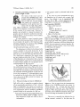
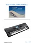
For example, the plot in Figure 1 was created using
the following code segment:
\begin(f igure) [htbl
\begin(center)
\fbox(\kern ipt \fbox<%
\insertplot(surf.pcl)(i.64)(2.13)))
\caption{This is output ... 3
\label(surf.pcl)
\end(center)
\end(figure>
a
GRAVITY DATA
(CONTWR IKTERVAL
-
8.761
a The space required for the graphics must be de-
Figure 1: This is output from the demonstration
diskette of the SURFER scientific data plotter by
Golden Software, Inc. A frame has been drawn
around the plot to show the "box" which
manipulates. When the graphics file has been properly
processed, the box defines the location of the graphics, and the image is surrounded by the frame.
fined as an \hbox (\mbox in IPW),with the
same dimensions (height and width) as the actual graphics.
This macro is essentially the definition for the
\pfig command contained in the plot.sty file
TUGboat, Volume 11 (1990), No. 2
202
which is part of CAPTURE. I t differs by the use of the
I P ' macro which
creates a box around the the text parameter and
surrounds it with a frame [2]. In this instance, the
\ i n s e r t p l o t box is substituted for the parameter
and a frame is drawn around it. The use of the frame
command again emphasizes that the \ i n s e r t p l o t
command is functionally identical to an \hbox in
The \fbox command drew a frame around
the graphic just as it would around any text block.
This construct also conveniently highlights the position where TEX thinks the graphics plot is located.
It is immediately apparent viewing Figure 1
and the macro defined above, that the graphics image is relocatable and has been positioned by
The insertion macro uses the \begin<center) . . .
\end(center) environment to center the plot in the
current l&X context. Because TUGboat is typeset
in a two column format, the image is centered in a
column, as it should be. However, if this same article were typeset in a single column format, the plot
would be automatically centered in a page.
The \ i n s e r t p l o t command also contains the
\ s p e c i a l command which instructs the device
driver t o load and print the graphics file at the
present cursor location. In order for the graphic
t o be positioned properly inside the \hbox (inside
the frame), the location of the graphic must be well
defined with respect t o the \ s p e c i a l command and
the \ s p e c i a l command must have a well defined
location inside the box. Fortunately, the definition
of the \ s p e c i a l command from Knuth [6] specifies
that it will have a unique, well defined location on
the page: "Therefore it is implicitly associated with
a particular position on the page, namely the reference point that would have been present if a box of
height, depth, and width zero had appeared in place
of the whatsit" [6]. If the position of the graphic is
linked to the location of the \ s p e c i a l command, it
will also have a well defined location that can be
placed inside the \hbox.
The technology for connecting the graphics to
the \ s p e c i a l command is based on the LaserJet
command structure. The LaserJet PCL language
contains a control code which says in effect: "start
the graphic at the present cursor location" [7]. If
the graphics file contains this control code, then
the image will be inserted starting at the location
of the \ s p e c i a l command, which is well defined,
and will be centered inside the \hbox defined by the
\ i n s e r t p l o t command. This is the technique used
by CAPTURE to allow
to manipulate graphics in
the same way as text.
\fbox command. \fbox is a
w.
m.
An important requirement however, is that the
graphics file contain only this relative positioning
command (start the graphic at the present cursor location) and n o other positioning c o m m a n d s .
The reason is that other positioning commands will
either override the relative position command, or
change the cursor location so that it no longer is
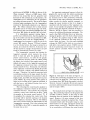
coincident with the location of the \ s p e c i a l command. As an example, the graphic in Figure 2 was
inserted using the identical commands as Figure 1.
However, the file in Figure 2 was not processed t o
remove the additional positioning commands. The
result is that
still thinks there is an \hbox containing the graphic, and even draws a frame around
it. However, the graphics image is offset relative
t o the \ s p e c i a l command so the image does not
appear inside the frame. For this reason CAPTURE
contains the F I X P I C utility which is run automatically after every graphics capture. FIXPIC removes
all of the positioning control sequences except the
relative position command, which it may insert if
necessary.
rn
II
G R A V I T Y DATA
c coNT-
INTER^^
= 6.76)
Figure 2: This figure is the same as Figure 3, except that the positioning commands have not been
removed from the image file. The frame has again
been drawn where
thinks the graphic is located.
However, because the graphics file was not properly
processed, additional positioning commands remain,
and the image is offset.
The example shown in Figure 2 is relatively benign. The positioning sequences in the graphics file
specified a relative position, so the image is offset
somewhat from the position of the \ s p e c i a l command. However, it is more common to find absolute positioning commands in graphics files. These
commands simply place the graphic image at some
fixed location on the page, and ignore entirely the
present cursor position [7]. Therefore there would
be no correlation at all between the actual location
TUGboat, Volume 11 (1990), No. 2
of the graphics and where TEX thinks the graphics
are located.
All of the application programs we have tested,
which provide LaserJet graphics, have used absolute
positioning commands. This choice is logical. An
application program has no way of knowing a priori the location of the LaserJet cursor. Attempting
to write the graphics at the present cursor location
would be dangerous, because the graphics could appear anywhere on the page. Conversely, the developers of these programs probably want the graphics
to be somewhat centered, and they can control the
graphics position unambiguously with absolute coordinates.
The problem of converting these captured
graphics files into a m - c o m p a t i b l e format is complicated because there are several different LaserJet
positioning codes. There are 2 codes for specifying
either graphics start at the cursor or at the left hand
side of the page, 6 relative positioning codes (relative to the old cursor position) and 6 code sequences
which place the cursor at an absolute location on
the printed page. All must be removed from the
graphics file (except the relative positioning command code) without disturbing any of the graphics
data.
Another problem is the use of additional vertical white space by some graphics applications.
White space is simply a series of null data transfers before or after the graphical image. Most of
the application programs we tested added some extra white space around the image. These programs
make no assumptions that the images produced
might eventually be included in TEX documents, so
the additional white space may have been included
for convenience. In some extreme cases, white space
was used t o position the graphics on the page as
an alternative to the position commands. If it is
not removed, the additional space will distort the
page layout and aesthetic appeal of the document,
pushing the rest of the text and graphics far from
a particular plot. In extreme cases it can force a
premature page eject. Another function of FIXPIC
is to remove all leading and trailing white space in
a graphics file. Spacing between the graphics and
the text can then be determined t o satisfy aesthetic
appeal, and is controlled by TEX.
2.2
A b s o l u t e c o o r d i n a t e s : the e x c e p t i o n t o
TEX p o s i t i o n i n g
Unfortunately, some graphics files cannot be processed so as to be relocatable. There are applications which use absolute positioning commands
throughout the graphics file instead of just at the
beginning. The reason is that absolute positioning
commands can considerably reduce the size of the
file and the concomitant time to print. This issue is
important for LaserJet printers without additional
memory space. Most applications which we have
tested do not use this method; rather, white space
is used t o position the LaserJet cursor. This method
requires a larger file and more time to print, but the
entire image can be moved by changing the position
of the cursor at the start of printing.
When absolute position commands are embedded throughout the file (as opposed to being placed
at the beginning only), the CAPTUREd file cannot be
positioned by
The graphics can be captured
and included in a TJ$ document, but the position
will be determined by the application program. If
an attempt is made to force relocation, the image
will be distorted because parts of the image will be
placed at different locations. CAPTURE has an option
which enables absolutely positioned graphics to be
included in TEX without distortion; however, T@
cannot control the position of the graphics. The application program must specify the plot location t o
be the proper position for the TEX document.
This problem is not entirely intractable. Most
programs which use absolute position coordinates
do so for only the horizontal coordinate. The vertical position is specified only once at the beginning
of the file, and will be removed by FIXPIC. If the
desired horizontal position of the graphics can be
easily defined (centered for example), then the application program can generally achieve the proper
position. The plot will appear at the same location
in
and will have a vertical position depending
on its location in the file.
We hope to address this problem further in a future release, by translating an absolutely positioned
file to a relatively positioned one.
m.
m,
3
The P K / T F M f o r m a t
The logic that graphics should be
functionally equivalent to text can be
extended by converting a graphic image file from the LaserJet PCL language to the PK and TFM formats
which are specific t o
[8, 91. A
graphic image in the combined P K /
TFM format isn't equivalent to a font of type, by definition it is a font of type. For example, the graphic
at the beginning of this paragraph was generated by
converting the graphic seen earlier from the PCL format to the PK/TFM format using the CONVERT utility in CAPTURE. It was inserted using the same \drop
macro described earlier and the code sequence:
TUGboat, Volume 11 (1990), No. 2
204
\f ont\largef ont=logo
\drop{a) The l o g i c t h a t ...
The immediate benefit of this approach may not
be clear. Operationally, there seems to be little difference between using the \ i n s e r t p l o t command
and the PK/TFM format, except that the PK/TFM
format may be less convenient: two files are created
instead of one. However, the advantages of using
a PK/TFM version of a graphics file accrue from
its device independent nature. For example, none
of the commercial 'l&X page previewers will display
graphic images included with the \ s p e c i a l command. However, graphics in the PK/TFM format
can be viewed, although some previewers we have
tested have memory limitations for large images.
Another benefit is that CAPTURE can be used
to supplement the graphics for other systems (nonLaserJet). We have argued that a graphics capture
utility is unnecessary for Postscript-based systems,
because the PostScript language describes both text
and graphics and the two can be mixed easily. However, the graphics sources are limited because there
are relatively few applications on PCs which support PostScript, due t o the high cost, and these
tend to be concentrated in the desk-top publishing
area. Fortunately, many of the PostScript drivers
for P C based systems use the same PK/TFM font
files as the LaserJet drivers [lo]. Therefore, captured graphics files which are converted to the PK/
TFM format can be used with PostScript drivers for
The domain of graphics sources for inclusion
in Postscript is increased considerably because far
more applications support the LaserJet PCL language than support PostScript.
This idea can be generalized by realizing that
the PK/TFM format provides a level of device independence, one of the hallmarks of the
design [3]. Once a PK/TFM file pair has been created, the graphics should be usable on any system
that uses the same resolution (300 dots per inch).
This set includes the LaserJet systems for which
CAPTURE was originally targeted, screen previewers,
and PostScript systems. We have yet to fully test
this idea on other 300 dpi drivers, say for the HP
DeskJet, but the idea is intriguing and has been
tested on PostScript drivers [lo].
This approach also suggests a general design
path for future extensions. We have argued that
separate CAPTURE-like programs may be necessary
for each computer/printer combination. However,
the PK/TFM standard provides a level of device independence such that a CAPTURE-like program may
be needed only for each computer/resolution combination.
w.
3.1
N a t u r a l conversions f o r a
system
graphics
The benefits of a PK/TFM conversion utility also
suggest other areas where file format conversion may
be useful. File conversion generally does not offer
a new source of graphics because it is somewhat
redundant with printer or screen capture. However, converting from the LaserJet PCL language
to the formats of graphical drawing or paint programs would be useful. The application program
would still generate the graphic image, saving the
user a considerable amount of work, but the captured graphics could be edited into a final form
before inclusion in a document. As a test of this
idea, the CAPTURE CONVERT utility will convert t o
the PC Paintbrush PCX format [5].
4
The case f o r limited screen c a p t u r e
We maintain that the best method for obtaining
graphics is printer capture because of the large
source of graphics at high resolution. File format
conversion generally offers few additional graphics
sources, and screen capture generally provides low
resolution. However, there are two cases which we
have identified in which printer capture is not practical. Both are apparently quite unusual. The first
case is an application program which mixes text and
graphics in the printer output. An example is the
scientific program MathCAD, by Mathsoft, Inc.
Printer capture is not practical with MathCAD
because it mixes text characters with the graphics
output. Although the output can be captured, the
docu$
resulting file cannot be inserted into a 'I)
ment and retain the original likeness. The solution
in this instance is to use the screen capture utility, CPTS, included with CAPTURE. CPTS captures
the screen image and writes it to a file that can be
included in a
document [5]. Screen capture effectively converts the text characters into a graphic
representation because they are displayed in graphics mode and can be resolved into individual pixels.
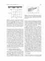
Moreover, there is no loss of resolution. The MathCAD printer output is a direct image of the screen
display. An example of screen capture from MathCAD is shown in Figure 3.
Other examples are programs which use installable device drivers in the DOS conf i g . s y s file.
Fortunately, this construct is rare, because device
drivers for a specific application remain in memory, attached to the operating system regardless of
whether the particular application is being used.
Valuable memory is wasted and the operating system is cluttered. However, some applications use
TUGboat, Volume 11 (1990), No. 2
Total
.
i
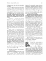
F i g u r e 4: This is a plot of a high numeric aperture
wide field of view lens. The plot was obtained from
the lens design program: OPTEC-11/87 by SCIOPT
Enterprises.
F i g u r e 3: This plot is a screen capture from the
program MathCAD, by MathSoft, Inc. The original screen was CAPTURE^, converted to the PCX
format by CONVERT, edited on P C Paintbrush, and
converted back to the PCL format. It was then modified by FIXPIC to have a resolution of 150 dots per
inch, producing a plot with reasonable resolution
which fits nicely inside the columns of TUGboat.
this approach because it provides a uniform interface
to all display monitors and hard copy devices. An
example is the lens design program, OPTEC-11/87
by SCIOPT Enterprises. The CAPTURE printer utility is unable to capture the printer output because
OPTEC bypasses both DOS and the BIOS for the
printer output. However, the screen capture utility
works fine and there is no loss of resolution. Because the OPTEC interface uses a common set of
device drivers, a single raster image is maintained
in the program. The output to the printer is derived from the same raster image as the output to
the screen; the only difference is which device driver
is invoked. Therefore, the screen capture acquires
the same image as the printer output. An example
of an OPTEC-11/87 image is shown in Figure 4.
The intent of this discussion is to acknowledge
that screen capture is a necessary utility for a general graphics capture system. Although it is not the
best method in most cases, there are instances when
it is the only method that will work.
4.1
Memory management a n d t h e
t e r m i n a t e a n d s t a y resident o p t i o n
The last issue to be considered is the general architecture of a graphics capture utility in the MS-DOS
environment. This issue is not applicable to the
general TEX graphics problem, but is entirely specific to the IBM/DOS implementation. A distinct
limitation of DOS is the 640k memory limit, which
has been a particular nemesis for large, complicated,
programs. A premise of the CAPTURE design was that
it could be used with large application programs,
and that both CAPTURE and an application program
would occupy memory simultaneously. Therefore,
memory size became an important issue.
These considerations lead to a design for
CAPTURE which minimizes the use of memory while
the application program is running. For example,
the postprocessing phase is explicitly removed from
the image capture routine, the printer and screen
capture routines are kept to the minimum size possible, and as many features as possible are incorporated into the postprocessing program. Also, the
postprocessor is spawned by the image capture routines only after the application program has exited.
Finally, CAPTURE does not use a terminate-and-stayresident (TSR) design. Although a TSR will take
no more memory than a normal program, a TSR
must be explicitly removed from memory before the
storage is released. If any programs are loaded after
the TSR, memory can be fractured and the released
storage is not contiguous with remaining memory.
Instead, the sequence of operation for CAPTURE
runs as follows. The image capture routines modify the operating system in order to capture graphics output and then spawn the application program.
The application program runs and presumably attempts to output graphics to the printer. Once the
application program exits, CAPTURE loads the postprocessor program, FIXPIC. When all processing is
complete, CAPTURE meticulously returns the operating system to its original state, releases all its memory, and exits. The memory used is a minimum and
is never fractured.
5
Conclusions
We have tried to extend our initial thesis that
provides an excellent medium for including graphics
TUGboat, Volume 11 (1990), NO. 2
with text. In the case of the PC/DOS implementation in particular, graphics applications are ubiquitous so there is a wide array of graphics sources.
Moreover, we have suggested a method for includthat allows T# the same
ing graphics with 'l$J
control over graphics images as fonts of type. This
approach affords a seamless blend of graphics and
text in the same document. The distinction between
is softened. Although the
device driver and
graphics insertion occurs at the device driver level,
the control is retained in
This idea has been extended to include the n u
tion of converting graphics files to the PK/TFM format of
The primary benefit of this approach
is expanding graphics capture to
implementations which do not use the LaserJet printer. In particular, CAPTURE can support Postscript drivers for
TEX that use the same computer modern fonts in the
PK/TFM format as the LaserJet drivers. The range
of graphics sources available to Postscript users is
considerably increased over the range of applications
which presently support Postscript. Other extensions may also be possible.
We have consistently emphasized that CAPTURE
serves as an example and proof-of-principle that
the graphics capability of
is considerable. We
would like to propose (hopefully without being
presumptuous) that other graphics implementation
programs adopt some of the ideas discussed here.
For example:
should be able to manipulate graphics images equivalently to fonts of type.
A graphics program for
should support the
PK/TFM format to maintain the greatest possible device independence.
In this way, the distinction between graphics and
text in
should be diminished and a connection
can be
between the various implementations of
maintained by the device independent nature of the
standard
formats.
w
w.
m.
David G. Cantor. "DROP.STY." Published in
W h a x , number 16, 1988. Available on the
Clarkson Archive Server (public domain).
CAPTURE, A Program for Including Graphics in 7&Y. Wynne-Manley Software, Inc., 1094
Big Rock Loop, Los Alamos, NM 87544, March
1990.
Donald E. Knuth. The m b o o k , pages 228229. Addison-Wesley Publishing Company,
1986. ISBN 0-2-1-13448-9.
LaserJet series II User's Manual. Hewlett
Packard Corporation, Boise Division, P.O. Box
15, Boise, Idaho 83707, December 1986. Part
NO. 33440-90901.
Font Metric Files." TUG[8] David Fuchs.
boat, 2(1):12- 17, 1981.
[9] Tomas Rokicki. "Packed PK Font File Format."
TUGboat, 6(3):115- 120, 1985.
[lo] w P R I N T / P S User Guide. Oregon House
Software, Inc., 12894 Rices Crossing Road, Oregon House, CA 95962, 1988.
"m
o Lee S. Pickrell
Wynne-Manley Software, Inc.
C/o Micro Programs, Inc.
251 Jackson Ave.
Syosset, NY 11791
m
w
m
References
w
Lee S. Pickrell. "Combining Graphics with
on IBM PC-Compatible Systems with LaserJet
Printers." TUGboat, 11(1):26 - 31, 1990.
A Document PreparaLeslie Lamport.
tion System, Users Guide 63 Reference Manual.
Addison-Wesley Publishing Company, Reading, Mass., 1986. ISBN 0-201-15790-X.
Donald E. Knuth. The m b o o k . AddisonWesley Publishing Company, 1986. ISBN O2-1-1344g9.
fim,
(516) 921-1351
Resources
Data General Site Report
Bart Childs
The distribution with the new versions of l&X and
METAFONT is nearly finished. We are also rewriting
the drivers for the DG, QMS, and LaserJet printers
in Silvio Levy's CWEB. We have decided to use Tom
Rokicki's PostScript drivers.
o Bart Childs
Dept. of Computer Science
Texas A&M University
College Station, TX 77843-3112
bartQcssun.tamu.edu