1
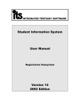
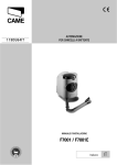
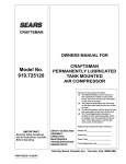
ACC01- UNIVERSAL
SINGLE PHASE AC
CONTROLLER CARD
Installation and User Manual
ENG
Manufactured By Martin Electronics cc
PO BOX 49284, ROSETTENVILE 2130
Republic of South Africa
AFR
Vervaardig Deur Martin Electronics cc
Posbus 49284, ROSETTENVILE 2130
Republiek van Suid Afrika
ESP
Fabricado por Martin Electronics cc
PO BOX 49284, ROSETTENVILE 2130
la República Surafricana
DEU
Hergestellt durch Martin Electronics cc
PO-Kasten 49284, ROSETTENVILE 2130
Republik Südafrika
POWERED BY
Technical Support
For technical
queries relating
to use/installation
of this product!
+27 11 433 4084
Table of Contents
4
5
6
6
7
8
Required Equipment ................................................................................... 9
Module Detailed Description ......................................................................
Card Features ..................................................................................
Electrical Terminals and Descriptions ..............................................
High Voltage Connections ...............................................................
Low Voltage Connections ................................................................
General Connection Diagram ..........................................................
10
10
11
11
12
13
ACC01 Operational Details .........................................................................
Auto-Close Feature ..........................................................................
Auto-Close Override .........................................................................
Pillar/Courtesy Lamp ........................................................................
Pedestrian Mode ..............................................................................
Free Exit ...........................................................................................
Safety Beam .....................................................................................
Status LED Output ...........................................................................
Zero Crossing Feature .....................................................................
Auxillary Power Output ....................................................................
14
14
14
14
14
14
15
15
15
15
System Programming and Advanced Features .......................................
Auto-Close Setting ...........................................................................
Auto-Close Override Facility ............................................................
Programming Remote Controls .......................................................
Erasing Remote Controls ................................................................
Lamp Control Button ........................................................................
16
16
16
17
17
18
Troubleshooting Guide ..............................................................................
Addendum: Shutter Door Applications ....................................................
Shutter Door Software and Ordering Information ...........................
Accessory Board ADB01b & Motor Preparation .............................
Motor Preparation Step 1 & 2 .........................................................
Motor Wire Functions .....................................................................
Limit Switches ................................................................................
Control Console .............................................................................
Wiring Diagram - Single Phase ......................................................
Product Specification ...............................................................................
Technical Specifications & Dimensions ..........................................
19
20
20
21
22
23
25
27
29
30
30
3
ENGLISH
Company Profile ...........................................................................................
Warnings and Cautions for Use .................................................................
Introduction ..................................................................................................
Product Description and Applications ..............................................
Package contents and Optional Extras ............................................
Compatible Systems and Replacement ..........................................
Company Profile
The company manufactures
remote controls, receivers,
infrared beams and garage
door automation products
under the Sentry brand
name.
The company also manufactures products for OEM (Original
Equipment Manufacturers) and custom markets and is deeply
respected in this regard as it designs and manufactures not only
its own products but specialised and custom products for
specific customers and provides support for these products.
MARTIN ELECTRONICS strives to give service and backup
second to none. Technical staff, as well as our engineers are
available to give answers to technical or installation problems.
The equipment is installed countrywide and is available through
a network of distributors in South Africa.
Further information is available on our website
www.martin-electronics.co.za
© Martin Electronics cc 2009
Martin Electronics cc. reserves the right to make changes to the products described in this manual without notice and without obligation of
Martin Electronics cc to notify any persons of any such revisions or changes. Additionally, Martin Electronics cc. makes no representations
or warranties with respect to this manual.
No part of this document may be copied, stored in a retrieval system or transmitted in any form or by any means electronic, mechanical,
optical or photographic, without the express prior written consent of Martin Electronics cc.
ENGLISH
Martin Electronics is a
respected and well-known
manufacturer of RF
remote controls and security
products and has
established itself as the
leader in RF remote control
for the past 20 years.
WARNINGS AND CAUTIONS
1.
Read all instructions and warnings
carefully before installing the product
2.
The product must only be installed by suitably
qualified persons.
3.
NEVER allow children to play with the system
or its remote controls.
4.
Secure all remote controls and opening
devices to prevent unauthorized access to the
display system.
5.
Before attempting any work or
maintenance on the product, disconnect
the power and remove the batteries (if
applicable)
9.
The installer has a responsibility to explain to
the owner/user how the system operates
and how to deal with potential emergencies
that may arise during the scope and course
of the product's application. The installer
must also pass on these instructions to the
owner/user
10. The product is designed and manufactured
only for the applications intended in this
manual. Any other use renders the warranty
null and void and neither the manufacturer or
its distributors, affiliates, servants, etc. shall
be held liable for any loss or damages
whatsoever.
11. This product is designed to be compatible
with the systems indicated, and updated
from time to time. Satisfactory performance
cannot be guaranteed for systems that are
not expressly listed as compatible.
6.
All modifications not expressly approved by
the manufacturer are forbidden.
7.
Do not install the product in an explosive
atmosphere or in any location subject to heavy 12. Use of this product may render the warranty
moisture ingress.
of the target system null and void unless use
of this module is approved by the
Never short-circuit any wiring to and from this
manufacturer or its authorized distributor.
equipment for any reason.
8.
Technical Support
For technical
queries relating
to use/installation
of this product!
+27 11 433 4084
5
ENGLISH
PLEASE READ THE FOLLOWING WARNINGS AND CAUTIONS
BEFORE INSTALLING OR USING THE PRODUCT.
RISK OF ELECTRIC SHOCK AND/OR FIRE
DO NOT TOUCH ANY COMPONENTS WHEN POWER IS APPLIED
Introduction
It is designed to be a compatible replacement for systems where a similar control
card is used, such as sliding gates, swing gates, shutter door automation, and
garage door automation systems. The ACC01 is designed to work with limit
switches, which signal to the system when either the closed or open limit is reached.
Out the box, the ACC01 is a drop-in replacement for current and legacy mechanical
actuators manufactured by REMEZ, HANSA and others.
The advantage of the ACC01 is that it features an on-board code-hopping receiver,
capable of storing up to sixteen unique buttons, or transmitters.
The ACC01 is also capable of supplying large currents (up to 1A) on its auxillary
supply terminal, enabling the product to provide a supply for locks that are typically
used on some types of swing gate.
The ACC01 also features motor run timing, which allows the motor to run for a
maximum of sixty (60) seconds under all conditions. This avoids damage to the
motor should the limit switches fail.
The ACC01 also features a PEDESTRIAN mode for gate applications, Auto-Close
facility (with override mode) and a fully controllable pillar lamp relay. All inputs are
provided with STATUS indicators, and a test button is included on the card itself.
The ACC01 includes full lightning and surge protection as standard. The motor
relays are also protected against excessive arcing by zero-crossing switching. All
connections are pluggable, ensuring quick and easy replacement. Pin connection
order and signals are industry compatible.
Finally, the ACC01 is fully customizable for OEMs and for volume customers.
Please contact MARTIN ELECTRONICS for further details.
Applications
• Swing Arm Gates (typically in-ground type units)
• Hydraulic Actuator Swing Gates (FAAC, etc...)
• AC Sliding Gate Motors
• Shutter Door Actuator Systems
• Curtain Actuation Systems
• AC Garage Door Actuator Systems
6
ENGLISH
The SENTRY™ ACC01 is a general-purpose or "universal" AC Motor Control
Card for general applications where it is necessary to control a single-phase
AC motor within defined limits.
Introduction
ENGLISH
SENTRY™ ACC01 Package Contents
=1 pc Controller Card and Instruction Manual
Optional Extras
SENTRY™ Code Hopping Remotes
(1 / 3 / 4 Button)
SENTRY™ Utility Enclosure
SENTRY™
Infra-Red Beam
IRB/W01
7
Introduction
The ACC01 is compatible with the following actuators as a rough guide
(Other operators may exist that will work well with this product)
Brand
REMEZ
FAAC
CAME
Model Number(s) / Type(s)
Swing Standard
Swing Fast
Swing Heavy Duty
1103 Slider†
1105 Slider†
413 LS
415 LS
Ferni (230V Version)
FAST (230V Version)†
ZA3N Control Panel‡
FROG-A
FROG-AV
HANSA DELUXE
HANSA /
NICE
VF Series (using three-phase
contactors)††
BONFIGLIOLI
CP91 Controller Card
CENTURION
The above is not an exhaustive list. In general, any single-phase AC motor fitted with limit
switches is suitable for the ACC01. Please bear in mind the upper limit of the motor power is
approximately 650 watts. Larger, and three-phase motors may be controlled by using two
three-phase contactors with single-phase coils.
† The ACC01 may not fit inside the original enclosure, but can certainly be mounted external to the actual
gate motor.
‡ Not all features may be identical.
†† Use of RVS Limit Switch Device is mandatory.
8
ENGLISH
Compatible Systems For Replacement
Required Equipment for Installation
ENGLISH
Philips screwdriver & Flat screwdriver
Small Side Cutter
Connecting Wire
• 1mm²
• 0.75mm²
Multimeter
9
ACC01 Detailed Description
ENGLISH
Card Features
1
3
2
10
4
5
9
6
7
8
6. On-board STATUS LED
7. Integrated 433MHz Receiver Module
8. Antenna
9. Transformer
10. LEARN Button
1. High Voltage Side Terminals
2. Pillar Lamp Relay (Potential Free)
3. Motor Relays
4. Signal (Low Voltage Side) Terminals
5. Auto-Close Adjustment
Lethal Voltages Exist on this card (module) during normal
operation. It is always mandatory to isolate all power before working
on any of the electrical connections!
10
ACC01 Detailed Description
ENGLISH
ACC01 Electrical Terminals and Descriptions
HIGH VOLTAGE TERMINALS
LOW VOLTAGE TERMINALS
AC
MOTOR
FUSE (5A)
DC SIDE
FUSE (1A)
WARNING: The Lamp Relay
contact is not fused! A fuse or
suitable circuit breaker MUST be
used in the lamp circuit to
prevent damage to the ACC01.
High Voltage Side Terminals & Descriptions
AC MAINS
E = Earth
N = Mains Netural
L = Mains Live Conductor
MOTOR
FWD = Motor Forward Winding
N = Motor Neutral or common
REV = Motor Reverse Winding
Motor Capacitor: The motor
capacitor should be connected
across the FWD and REV
terminals.
LAMP
A = Contact
B = Contact
(Potential Free Relay Contact for Pillar lamp or other use)
This card must be earthed via the "E" terminal otherwise the
effectiveness of the lightning protection will be severely impaired!
11
ACC01 Detailed Description
Pin Name
Description
Function
TRIG
MAIN TRIGGER INPUT
Controls the Motor in the sequence of
Forward -> Stop -> Reverse -> Stop. This
input is protected against lightning and may
be used over a distance i.e. intercom handset
PED
PEDESTRIAN INPUT
Opens the gate/door approx. 1/5th of the total
travel. Initiates a warning by causing the lamp
relay to flash before starting the motor
IRB
SAFETY BEAM INPUT
Input for a safety beam. Normally Closed
circuit, that will either stop, or reverse the
motor depending on state. During Forward
(opening) cycle, the input is ignored. During
Reverse (closing) cycle, the input will cause
the motor to stop, pause a short while and
then reverse. During Open state, activation of
this input resets the auto-close timer
(if enabled). If not used, this input must be
tied to COM with a wire link.
LED
STATUS LED OUTPUT
A Status LED output designed to drive an
external, remote LED inside an intercom
handset, over a distance. The pin is protected
against lightning.
LIT
LIGHT CONTROL INPUT
Control input for manual control of the lamp
relay from a remote location by using a push
button. Brief activation turns lamp on for the
lamp time. Press and hold for 5 seconds
invokes override mode where lamp is
permanently on.
FRX
FREE EXIT INPUT
A special trigger input, that will cause the
motor to drive forward (open) only. It will also
reset the auto-close timer if the system
is in the open state. It will also cause a
reversal (stop and reverse open) if the system
is in the process of closing.
OLS
OPEN LIMIT SWITCH
Limit switch input. Opening the circuit will
register the open limit, resulting in the motor
stopping if it was travelling forward (opening)
CLS
CLOSED LIMIT SWITCH
Limit swith input. Opening the circuit will
register the closed limit, resulting in the motor
stopping if it was travelling in reverse
(closing)
12V
AUXILLARY POWER SUPPLY
Unregulated DC 12V output for auxillary
equipment such as the safety beams,
additional remote control receivers, access
control keypads, etc...
Max current that may be drawn is 1A!
COM
COMMON (NEGATIVE)
Common terminal (negative) for signals and
auxillary power supply. 5 in total
The TRIG input, and LED output are the only two signals designed to be connected
to an intercom handset via a long cable run as they are protected. All other inputs
are not designed for use over long cable runs. Failure to observe this will result in
the risk of lightning damage to the ACC01.
12
ENGLISH
Low Voltage (Signal) Side Terminal Descriptions:
ACC01 Detailed Description
ENGLISH
General Connection Diagram
Fuse/Breaker
Pillar/Courtesy
Lamp
Capacitor
AC
1-ph
Induction
Motor
M
LIVE
NEUTRAL
B
Trigger
A
REV
N FWD L
N
E
TRIG
COM
Pedestrian Opening
PED
Safety Beam
IRB
COM
STATUS LED
Fit wire link as shown
if beam is not fitted
LED
LIGHT CONTROL
BUTTON
LIT
Free Exit Opening
FRX
Open Limit Switch
OLS
Isolator
COM
COM
Closed Limit Switch
CLS
To
Distribution
Point
12V
DC Output
COM
Diagnostic Indicators
The ACC01 is equipped with diagnostic indicators that
are useful for fault-finding and verifying installation:
Normally Open Inputs:
TRIGGER
PEDESTRIAN
FREE EXIT
TRIGGER
PEDESTRIAN
These inputs have RED indicators, that light when the circuit is closed
SAFETY
BEAM
FREE
EXIT
OPEN
LIMIT SW
CLOSED
LIMIT SW
AC
STATUS
STATUS
LED
Normally Closed Inputs:
IR BEAM
OPEN LIMIT SWITCH
CLOSED LIMIT SWITCH
These inputs have GREEN indicators, that light when the circuit is in
the correct state, and turn off when the circuit is broken e.g. IR Beam is
broken.
The AC STATUS indicator is always on when the card is powered up.
If it does not light, it means there is no power on the card.
13
ACC01 Operation
The ACC01 operates in an industry-standard manner, providing full gate/door control
via a trigger input. The general method of operation is that each activation of the
trigger will stop all motion, if the gate/door was in motion, and will start the gate/door
moving if it was stationary.
Auto-Close
The ACC01 provides an auto-close function which can be set between OFF and a
maximum of four minutes. Turning the shaft on the board fully anti-clockwise will
disable AUTO-CLOSE. Turning the shaft clockwise allows adjustment of the autoclose time from a minimum of 15 seconds to a maximum of four minutes.
Auto-close will close the gate/door automatically if it was open, or partially open.
Auto-Close Override Mode
The auto-close mode, can be overridden i.e. disabled for the current cycle, by holding
the TRIGGER (trigger input or remote control) continuously when opening the
gate/door from the fully closed position. Once the remote/trigger input has been
detected as being held for 5 seconds or more, the gate/door will stop as
acknowledgement, and when the remote control/trigger input is released, the
gate/door resumes opening. The override mode is cancelled once the gate/door is
fully closed.
Pillar/Courtesy Lamp
The ACC01 provides a relay for controlling the standard pillar/courtesy lamp. When
the gate/door is triggered to open, the lamp will be turned on. When the gate/door is
stopped by either the user pressing the remote, or it reaching its open limit, the lamp
will remain on. However if auto-close is disabled, the lamp will turn off after two
minutes. The lamp also turns off 2 minutes after the last gate transaction is
completed. The "LIT" lamp control input allows for manual control of the lamp and is
designed for connection to a push button. Pressing the button briefly, with the gate in
the fully closed state, will turn on the pillar lamp and it will remain on indefnitely. This
override state is indicated by short flashes on the STATUS LED. Activating the input
again, clears this mode.
Pedestrian Mode
The ACC01 provides a standard Pedestrian Key-switch input. When activated, the
pillar lamp relay will pulse for 5 seconds, thereby flashing the pillar lamp as a warning
that the gate/door is about to open. The gate/door will then be open about 30% of the
nominal travel, and then stop. If the trigger input is invoked during the pedestrian
mode running, or when the gate/door has opened partially, pedestrian mode will be
cancelled and the gate will open fully as per normal.
Free Exit
The ACC01 provides a free-exit input, which, as the name implies, allows only an exit
condition. This input will only invoke opening cycles, and if the system is closing, will
14
ENGLISH
ACC01 Operational Details
ACC01 Operation
Free Exit (cont.)
result in a full stop, a short pause, and re-opening known as a reversal. If the
gate/door is fully open, activation of the FREE EXIT input will reset the auto-close
timer if enabled. Generally, the auto-close timer should always be activated when
using the FREE EXIT input, otherwise there will be no way of closing the gate/door.
Safety Beam Input
The ACC01 provides a standard safety beam input, which is designed to prevent the
gate/door crushing or colliding with people/objects in its path. The beam input is a
normally closed circuit, which, if not used must be bridged with a wire link
between IRB and COM terminals. The beam input, will reset the auto-close timer if
the system is fully open, and during closing, a short beam break will result in a pause
i.e. the gate/door stops for about 1 1/2 seconds then resumes closing. A longer beam
break will result in a reversal, and the gate/door will re-open fully.
Status LED Output
The ACC01 has a standard STATUS LED output as well as an LED on board to
indicate the status during installation/testing. The output pin is designed to directly
drive a standard LED, over a long cable run, and is fully protected against lightning.
The status LED indicates system status as follows:
System State
LED Indication
Fully Closed
LED is off
Running Open
LED flashes slowly (1 flash/sec)
Fully/Partially Open
Closing
Pedestrian Opening
LED is on
LED flashes fast (2 flash/sec)
LED flashes very fast (4 flash/sec)
Zero-crossing Switching
To reduce mains borne switching noise, and primarily to prolong the life of the control
relays, the ACC01 is equipped with zero-crossing switching. This means that the
motor is switched on, or off during the zero crossing point of the mains waveform.
While this does not entirely eliminate relay contact arcing, it does substantially reduce
the severe arcing that would otherwise result, which if left uncontrolled, leads to
premature failure of the ACC01.
Auxillary Power Output
The ACC01 can provide, up to 1 Ampere of current for external equipment on its
auxillary output terminal. The output is protected by fuse F1, which is closely mounted
to the signal connector.
15
ENGLISH
ACC01 Operational Details (cont.)
Programming & Advanced Features
The ACC01 involves minimal programming, aside from learning remote controls into the built in
receiver.
Setting up the Auto-Close Timer
The auto-close time may be adjusted
by turning the potentiometer located
on the ACC01 as shown.
Turning the pot fully anticlockwise will DISABLE the
auto-close timer completely.
Turning the pot clockwise will
adjust the auto-close time from
between 15 seconds and a maximum
of 240 seconds (4 minutes, with the pot
turned fully clockwise)
9
Notes about auto-close
Turning the control fully anti-clockwise until it stops, turns off auto-close completely. Turning the
control slightly clockwise sets auto-close time to the minimum, about 15 seconds. Turning the
control fully clockwise until it stops, sets auto-close to 240 seconds, or four minutes.
It is MANDATORY to have a safety beam connected to the system
when using auto-close, as this will prevent accidents and collisions
from occuring with a gate that could open at any time.
Pedestrian mode auto-close is not adjustable, therefore this setting does not affect the
pedestrian gate/door in any way. Even if auto-close is fully disabled, the pedestrian gate/door
will still auto-close
Auto-Close Override Facility
If auto-close is enabled, it may be temporarily disabled (that is, for the current gate/door cycle)
by pressing and holding the TRIGGER or the remote control, for 5 seconds when opening the
gate/door from the FULLY CLOSED state. When the trigger is held for 5 seconds at least, the
gate/door will stop and pause, providing acknowledgement that the override has been set.
When the trigger is released, the gate/door will resume opening and open fully, and remain so,
until commanded to close by a trigger. When commanded to close, and the gate/door reaches
its closed limit, the override set, will be cleared, and auto-close will become operational again.
16
ENGLISH
Programming the ACC01
Programming & Advanced Features
Programming Remote Controls
The ACC01 allows up to sixteen (16) remote controls to be stored in its memory. Remote
control storage is automatically managed.
LEARN
Button
9
To learn a new remote control
1. Press and release the LEARN button on the ACC01
The STATUS LED emits short flashes
2. Operate the button on the remote control, you wish to program into the ACC01, at a distance of at least 1
metre away from the ACC01. When successfully learnt, the STATUS LED will turn on for 1 second.
Thereafter learn mode is exited and the product resumes normal operation.
To Erase all remote controls
1. Press and hold the LEARN button on the ACC01
2. After about 5 seconds, the STATUS LED will flash slowly. Release the LEARN button
3. The STATUS LED will begin to flash rapidly for up to 10 seconds as all data is erased. When finished,
the ACC01 enters learn mode allowing a new transmitter to be learnt in at that point. If the user does not
wish to learn new remotes in at this point, simply leave the ACC01 to time-out, after 10 seconds, in
which case normal operation resumes.
• Learn mode exits automatically when, either a remote
control is learnt into the system, or, the system is left to
time out after 15 seconds (i.e. no remote is learnt into the
system)
• It is not possible to erase an individual remote. Only a
mass-erase of all remote controls can be performed to
erase lost or stolen remote controls.
17
ENGLISH
Programming the ACC01(continued)
Programming & Advanced Features
18
ENGLISH
Lamp Control Input
The ACC01 provides a lamp control input which operates in an industry
standard manner via a push button or toggle switch. Activating the input will
turn on the lamp, and another activation will turn off the lamp. When the
lamp is turned on, the STATUS LED will indicate this by means of short
duration flashes.
Troubleshooting Guide
Problem
No response to triggers.
Possible Cause
No AC Power
Check for presence of AC mains, if
not present check for tripped circuit
breakers upstream of the supply
DC Fuse Blown
Locate DC fuse F1 on the ACC01
and replace it with a 1A quick blow
fuse.
Card Faulty
Return the ACC01 for repair/testing
Beam Input Disconnected
Check for disconnection by bridging
IRB terminal to COM. If card
operates then replace/repair wiring
Faulty IR beam
Check beam and adjust/repair as
necessary
AC FUSE Blown
Locate AC fuse F2 on the ACC01,
and replace with a 5A slow blow
fuse.
Motor Capacitor Faulty
Replace the Motor Capactior with a
similar type
Motor Faulty
Test the motor without the presence
of the ACC01, and repair/replace if
necessary
Short Circuit/Overload on
auxillary terminal.
Disconnect all wiring from the 12V
terminal. Replace fuse, and if the
card powers up, investigate for
short circuits on the auxillary line.
Card Faulty
Return the ACC01 for repair/testing
AC ON LED does not light.
System unresponsive
System powered up and
appears to work, but will
not respond to a TRIGGER
nor a FREE EXIT input
Relays Click when
triggered but gate/door
motor does not start
DC side fuse F1 keeps
blowing
Possible Solution
19
ENGLISH
Basic Troubeshooting Guide for the ACC01
The following is a basic guide to fault-finding the ACC01. In many cases
working through these will solve common problems. However, when in doubt
please call technical support, or, send the card in for testing/repair either
directly to MARTIN ELECTRONICS or via your distributor.
Addendum - Shutter Door Applications
The ACC01 is a suitable candidate for controlling generic shutter-door
motors. In most cases, the motor will need to be modified to work with
the ACC01, this entails modifications to the wiring and removal of
some unnecessary components from the shutter door motor. This
section is intended for professional installers who supply and fit a
range of Chinese shutter door motors which are of the tubular type.
To operate the available types of shutter door motor, requires the ACC01 to
be supplied with a special software installation. This can be done on
production when you order your ACC01, or you can return the board to your
distributor and request that the SHUTTERDOOR software be installed. The
difference between normal software and the special shutterdoor variant is
that provision is made for the inverted limit switches, as well as the three
button control panel which is usually supplied with these types of motors.
The ACC01's wireless remote control receiver, however, works the same as
previously and will provide the expected, start-stop-reverse-stop sequence.
There are two types of shutter door motor in existence, one is a single phase
model, the other is a three phase variant, the ACC01 can be configured to
operate either type. The difference is how the connections are made
Most shutter door motors include a magnetic clutch, and to operate this
clutch correctly requires the addition of an adapter board, the ADB01b,
which can be purchased separately from your distributor. The ADB01b
provides the control voltage for the clutch ensuring it engages and
disengages correctly when the motor is started and stopped. It also provides
a convenient bonding point for the existing motor wiring to the ACC01
Shutter Door Motor Types the ACC01 has been tested with:
"Hualin" Brand HL series single phase (HL-200-1P thru HL-1000-1P)
"J & G" Brand series motors
Both these products are virtually identical from an electrical standpoint and
operate on the same principle, the differences being mainly mechanical.
These products often include a wireless remote control unit with remotes,
and a keyswitch, which are not needed when the ACC01 is installed.
However these components can still be used if the installer so wishes. The
next few pages, go into detail on how to connect these motors to the
ACC01.
20
ENGLISH
Using the ACC01 to control Shutter-Door Motors
Addendum - Shutter Door Applications (cont.)
MOTOR ADAPTER BOARD
ADB01b
The motor adapter board is purchased separately. In addition, you will need
suitable lengths of 1mm² wire to connect the ACC01 to this board.
Preparing the Motor for Retrofit (single phase models)
Virtually all the shutter door motors have a cover "cup" at the top end of the
motor, where all the electrical connections are made. Within this space is a
pair of relays, or contactors, depending on the manufacturer and motor type.
For a single phase motor, there is usually two relays/contactors present, to
which many electrical connections are made. Prepare the motor for
installation as follows:
1) Remove the relays/contactors completely and disconnect all wiring,
including the mains lead and wall control (three button up/down/stop panel).
All that should remain is a wiring loom that runs into the side of the motor,
where a cover exists to hold the motor capacitor, and two thin wires coming
out the top. The wiring loom will contain 9 wires, which includes the three
motor wires, two wires to the thermal cut-out and two pairs of wires, one to
each limit switch.
2) Retain the plastic panel that held the relays as it will be used for mounting
the ADAPTER BOARD, which has holes to match those on the plastic panel.
Since these motors are manufactured in the Far East,
there are often variances in motor wire colours. Always
double check the wire functions before attempting to
install the ACC01 on these motors!
21
ENGLISH
Accessories Required for Installation
Addendum - Shutter Door Applications (cont.)
1
Motor Top Section with cover removed
This is where the main control logic of the
motor is to be found, consisting of two
relays or contactors. The first step is to
remove both relays/contactors and
superfluous wiring. In some cases there will
be a small PC board with some
components, this is the brake actuating
circuit and can be removed. Once you have
removed all the wiring and components you
should be left with two thin wires going
down the top, which are the brake wires,
and the main wiring harness going into the
motor down a side hole, and on to the limit
switch unit.
Note: Retain the screws used to mount
the contactors/relays as they will be reused.
2
Existing Controls Removed
Once the relays/contactors are removed, all
that remains is a plastic platform as shown
alongside in the diagram. Note the arrow
pointing to the earth conductor, which
should be retained and attached to the
EARTH terminal of the ACC01. The plastic
platform is to be kept in place as it will be
used in the next step.
22
ENGLISH
Motor Preparation Steps
Addendum - Shutter Door Applications (cont.)
3
Fitting the ADB01b
The ADB01b is designed to mount on the
plastic platform as shown. The mounting
holes are indicated with arrows, the ADB01b
is designed specifically to align with the holes
that were used to hold the previous controls.
Mount the board as shown in the diagram,
using the screws that were removed when
you removed the contactors/relays and screw
it down firmly into place.
Depending on which side the wiring harness
into the motor is, the ADB01b can be installed
either way round, depending on your
preference and your convenience.
Checking Motor Wire Functions
At this point, prior to wiring the motor into the ADB01 adapter board, it is necessary
to confirm the wire functions on the supplied motor as variances are common due to
the nature of the product. The motor's internal wiring diagram is as follows:
FORWARD
M
NEUTRAL
REVERSE
thermal
THERMAL
THERMAL
mag brake
BRAKE
BRAKE
Thermal: The motor is fitted with a thermal cut-out switch, which is used to protect the motor.
Mag Brake: This is the electromagnetic brake used to stop the motor when power is removed, preventing
free race. Applying DC power to these terminals disengages the braking mechanism.
23
ENGLISH
Motor Preparation Steps (continued)
Addendum - Shutter Door Applications (cont.)
Confirm the motor wire functions using a multimeter set to measure ohms,
measuring between the points as shown. Note: motor winding and brake winding
resistances are approximate and may vary from manufacturer to manufacturer.
FORWARD
W
M
15,6W
A
REVERSE
W
31,1W
C
NEUTRAL
W
B
15,6W
thermal
THERMAL
THERMAL
W
0W
mag brake
BRAKE
BRAKE
multimeter set
to ohms( W )
W
436W
Note: Reading C will usually be
2 x A or B
FREQUENTLY USED COLOURS:
THICK BLUE x 2 = THERMAL CUTOUT
THICK RED = MOTOR FWD WINDING
THICK YELLOW = NEUTRAL
THICK GREEN = MOTOR REV WINDING
THIN RED AND BLACK PAIR =
MOTOR BRAKE
Once you have determined the correct wire functions from the above tests, the
ADB01b can be connected to the motor wires as shown.
THERMAL
THERMAL
REVERSE
NEUTRAL
FORWARD
BRAKE
BRAKE
24
ENGLISH
Motor Preparation Steps (continued)
Addendum - Shutter Door Applications (cont.)
The next step is to connect the limit switches correctly and to confirm that they are
working correctly. These types of motor operate on an "inverted" limit switch
principle, meaning that the contact is broken on the switch when the limit is reached,
and therefore when the door moves away from the respective limit, the contact is
once again made.
The shutter door motors employ a mechanical limit switch mechanism which looks
identical or similar to the following:
MECHANICAL LIMIT SWITCH MODULE
The switches within this unit are of the double pole type, therefore a total of eight
wires (including an earth) exit from this unit. There are usually three thicker wires,
included with two pairs of thinner wires, one set is orange, one set is brown (note
that colour variances may mean a different colour wire is used. If one looks through
the plastic cover you will usually be able to see that the one pair of thin wires is
attached to one limit switch, while the other pair is usually attached to the other limit
switch.
To Determine which limit switch is which: Use a multimeter to determine which
limit switch is open and closed limits respectively, by measuring across wire pairs
with the same colour, an open circuit or "OL" reading indicates the door is on its
limit. So for example if the shutter door is closed, the limit switch that is reading
open circuit is the CLOSED LIMIT switch. Make a note of which pair was open
circuit and wire as follows:
25
ENGLISH
Motor Preparation Steps (continued)
Addendum - Shutter Door Applications (cont.)
ENGLISH
Motor Preparation Steps (continued)
Limit switch unit internal wiring diagram
BROWN
BROWN
BLACK
WHITE
ORANGE
ORANGE
GREY
The thinner wires are the BROWN-BROWN and ORANGE-ORANGE pairs.
The thicker wires are not used when connecting the ACC01 and can therefore be
cut off or taped up into the wiring loom.
Having noted which limit switch pair is the CLOSED LIMIT, wire the limit switch pairs
onto the ADB01 as follows:
TO
OPEN LIMIT
SWITCH
TO CLOSED
LIMIT SWITCH
Once these connections are complete, the ADB01 can be mounted on the motor,
and then connected to the ACC01 as shown on the wiring diagram page.
26
Addendum - Shutter Door Applications (cont.)
The shutterdoor motor is supplied with a wall control console, which consists of
three buttons, which allow the user to raise, lower, and stop the door. It is of the
wired type and looks identical, or similar to the one shown as follows:
Wired Control Console
The ACC01, when installed with the SHUTTERDOOR firmware, allows control of the
shutter door motor as per normal, by simply connecting the wires of the control
console directly to the ACC01. Before that can be done, it is necessary to determine
which wires are connected to the buttons by using a multimeter.
WHITE
UP/
OPEN
RED
STOP
YELLOW
DOWN/
CLOSE
BLUE
Internal Wiring Diagram of Control Console
27
ENGLISH
Motor Preparation Steps (continued)
Addendum - Shutter Door Applications (cont.)
Control Console Connections (continued)
From the diagram it is clear that the open and close (or up and down) buttons are
normally open contacts, whereas the STOP button is a normally closed contact.
NB: The colour code shown is frequently correct, unfortunately there may be
variances, so it is important to check which wires are connected to which
buttons to ensure no installation errors occur.
Using a multimeter, determine which two wires are shorted, and then press the
STOP button to confirm that the short clears. Either one of the wires could be a
COMMON. Using either of these, press the UP/OPEN button and search amongst
the other wires until you find the correct one. Note which of the two first wires gave
you a reading, this is the COMMON.
The control console is wired into the ACC01, as follows:
OPEN/UP Button ------------- TRIGGER INPUT TERMINAL
COMMON --------------------- COMMON TERMINAL
CLOSE/DOWN Button ------ PEDESTRIAN INPUT TERMINAL
STOP Button ------------------ FREE EXIT INPUT TERMINAL
28
ENGLISH
Motor Preparation Steps (continued)
EARTH
to motor
chassis
THERM.
CUT
REV
N
FWD
FWD
REV
BRAKE
motor side
29
STOP
UP
DOWN
CONTROL
CONSOLE
COM
REV
N
FWD
OLS
COM
CLS
COM
12V
CLS
COM
OLS
FRX
COM
LIT
LED
COM
IRB
PED
COM
TRIG
ACC01
B
A
REV
N FWD L
N
E
NEUTRAL
LIVE
To
Distribution
Point
Isolator
Single-Phase Wiring Diagram
ENGLISH
ADB01b
Note:
Depending on installation
it may be necessary to swap
FWD and REV wires to get
motor to turn in the correct direction
Addendum - Shutter Door Applications (cont.)
Product Specification
200 - 250V AC 50/60Hz
650W max.
12 ~ 14V DC, maximum load = 1A
5A at 220VAC (500 watt tungsten load max.)
(250 watt metal halide lamp wattage max.)
Onboard Receiver:
433.92MHz code-hopping (rolling code)
Card Dimensions
3.8
137.5
3.8
134.4
ALL DIMENSIONS IN MILLIMETRES
HOLE DIAMETER = 4mm
30
ENGLISH
Operating Voltage:
Motor Rating:
Auxillary Power Out:
Lamp Relay Contact:
Ref: ACC01_MANUAL_V1_0.cdr