1
A Flexible 3D-Visualisation Engine
With Force-Feedback Support
Douglas Currie
Matriculation No. 9607170
Class SE4H
Session 1999/2000
Department of Computing Science
University of Glasgow
Lilybank Gardens
Glasgow, G12 8QQ
The 'Flight' Simulator
Page 2 of 117
Contents
1
Introduction______________________________________________________ 8
1.1
Purpose of Introduction _____________________________________________ 8
1.2
Summary of Project Results __________________________________________ 8
1.3
Motivation_________________________________________________________ 9
1.4
Overview _________________________________________________________ 10
1.5
Preliminaries _____________________________________________________ 11
1.5.1 Definition of Terms ______________________________________________________11
1.6
2
Project Software Engineering Process and Report Outline________________ 12
Requirements Specification ________________________________________ 14
2.1
Requirements Plan_________________________________________________ 14
2.2
Project Description ________________________________________________ 14
2.3
User Definitions ___________________________________________________ 14
2.3.1 Users _________________________________________________________________14
2.3.2 Developers _____________________________________________________________15
2.4
User Requirements_________________________________________________ 15
2.5
Developer Requirements ____________________________________________ 15
2.6
Non-Functional Requirements _______________________________________ 16
3
Risk Analysis ____________________________________________________ 16
4
Architectural Design ______________________________________________ 17
5
6
4.1
Structural Analysis ________________________________________________ 17
4.2
Structural Specification_____________________________________________ 17
Requirements Definition___________________________________________ 19
5.1
Flight Requirements _______________________________________________ 19
5.2
FlightLoader Requirements _________________________________________ 19
5.3
FlightLdr Requirements ____________________________________________ 19
5.4
EDSSplash Requirements ___________________________________________ 20
5.5
FlightBrowser Requirements ________________________________________ 20
Component Design _______________________________________________ 21
6.1
Design Plan and Implementation Considerations________________________ 21
6.2
Flight Task Language Design ________________________________________ 21
6.3
Flight Logs Design _________________________________________________ 21
6.4
Flight Design______________________________________________________ 22
6.4.1
6.4.2
6.4.3
6.4.4
Structural Specification ___________________________________________________22
Component Definition ____________________________________________________23
Interface Specification ____________________________________________________26
Dataflow Analysis _______________________________________________________26
Douglas Currie
The 'Flight' Simulator
6.5
FlightLoader Design _______________________________________________ 28
6.6
FlightLdr Design __________________________________________________ 29
6.7
EDSSplash Design _________________________________________________ 29
6.8
FlightBrowser Design ______________________________________________ 29
6.8.1
6.8.2
6.8.3
6.8.4
7
Page 3 of 117
Structural Specification ___________________________________________________30
Component Definition ____________________________________________________30
Interface Specification ____________________________________________________30
Dataflow Analysis _______________________________________________________30
Implementation __________________________________________________ 32
7.1
Implementation Plan _______________________________________________ 32
7.2
Flight ____________________________________________________________ 32
7.2.1 Visual C++ _____________________________________________________________32
7.2.2 The OpenGL API ________________________________________________________35
7.2.3 The DirectInput API______________________________________________________35
8
9
7.3
FlightLoader______________________________________________________ 35
7.4
FlightLdr_________________________________________________________ 36
7.5
EDSSplash _______________________________________________________ 36
7.6
FlightBrowser_____________________________________________________ 36
Unit Testing _____________________________________________________ 37
8.1
Test Plan _________________________________________________________ 37
8.2
Flight Testing _____________________________________________________ 37
8.3
FlightLoader Testing _______________________________________________ 37
8.4
FlightLdr Testing __________________________________________________ 37
8.5
EDSSplash Testing_________________________________________________ 37
8.6
FlightBrowser Testing ______________________________________________ 38
Integration and System Testing & Evaluation__________________________ 39
9.1
Test Plan _________________________________________________________ 39
9.2
Test Report _______________________________________________________ 39
9.3
Evaluation Plan ___________________________________________________ 39
9.4
Evaluation Results _________________________________________________ 40
9.5
User Manual ______________________________________________________ 40
9.6
Developer Manual _________________________________________________ 40
10 System Status____________________________________________________ 41
10.1 Flight Status ______________________________________________________ 41
10.2 FlightLoader Status ________________________________________________ 41
10.3 FlightLdr Status ___________________________________________________ 41
10.4 EDSSplash Status__________________________________________________ 41
10.5 FlightBrowser Status _______________________________________________ 41
10.6 Project Log Abstract _______________________________________________ 42
11 Extending the Simulator___________________________________________ 43
Douglas Currie
The 'Flight' Simulator
Page 4 of 117
11.1 Further Development_______________________________________________ 43
11.2 Integration _______________________________________________________ 43
11.3 Map Generators ___________________________________________________ 44
11.4 Structures ________________________________________________________ 44
11.5 Task Directives ____________________________________________________ 44
11.6 Control Modules___________________________________________________ 44
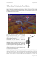
12 Case Study - The Helicopter Control Module __________________________ 46
13 Case Study - The ME Build ________________________________________ 50
13.1 Motivation________________________________________________________ 50
13.2 Design and Implementation _________________________________________ 50
13.3 Further Development_______________________________________________ 50
14 Project Evaluation________________________________________________ 52
14.1 Requirements Analysis _____________________________________________ 52
14.2 System Design_____________________________________________________ 52
14.3 System Implementation _____________________________________________ 52
14.4 System Evaluation _________________________________________________ 52
14.5 Achievements _____________________________________________________ 52
14.6 Shortcomings and Future Developments_______________________________ 53
14.7 Conclusion _______________________________________________________ 54
15 Bibliography ____________________________________________________ 55
16 Appendix A - Requirements Specification Document ____________________ 57
16.1 Project Description ________________________________________________ 57
16.2 User Definitions ___________________________________________________ 57
16.2.1
16.2.2
Users _______________________________________________________________57
Developers ___________________________________________________________57
16.3 System User Requirements __________________________________________ 57
16.3.1
16.3.2
Tasks _______________________________________________________________57
Simulation ___________________________________________________________58
16.4 System Developer Requirements _____________________________________ 59
16.5 Non-Functional Requirements _______________________________________ 59
16.5.1
16.5.2
16.5.3
16.5.4
16.5.5
16.5.6
Documentation ________________________________________________________59
Performance Issues_____________________________________________________60
Human-Computer Interface ______________________________________________60
Hardware Requirements_________________________________________________60
Exceptional Conditions and Error Handling _________________________________60
Distribution __________________________________________________________61
16.6 System Scenarios __________________________________________________ 61
17 Appendix B - Risk Analysis Document _______________________________ 62
17.1 Risk Planning _____________________________________________________ 62
17.2 Requirements Risks ________________________________________________ 62
17.3 Design Risks ______________________________________________________ 62
Douglas Currie
The 'Flight' Simulator
Page 5 of 117
17.4 Implementation Risks ______________________________________________ 62
17.5 Deployment and Lifetime Risks ______________________________________ 63
17.6 Project Management Risks __________________________________________ 63
18 Appendix C - Architectural Design Document _________________________ 64
18.1 Structural Analysis ________________________________________________ 64
18.2 Structural Specification_____________________________________________ 64
18.3 Component Definition ______________________________________________ 64
18.3.1
18.3.2
18.3.3
18.3.4
18.3.5
18.3.6
18.3.7
Flight Logs ___________________________________________________________64
Flight Tasks __________________________________________________________65
Flight Simulation Program_______________________________________________65
FlightLoader Front End _________________________________________________65
FlightLdr Front End ____________________________________________________66
EDSSplash Introduction Screen ___________________________________________66
FlightBrowser Data Viewer ______________________________________________66
18.4 Interface Specification ______________________________________________ 66
18.4.1
Flight Tasks __________________________________________________________66
18.4.1.1
Flight Task Language (FTL) _________________________________________66
18.4.2
Flight Logs ___________________________________________________________66
18.4.3
Flight Interface________________________________________________________67
18.4.4 FlightLoader Interface __________________________________________________67
18.4.5
FlightLdr Interface _____________________________________________________67
18.4.6
EDSSplash Interface ___________________________________________________67
18.4.7
FlightBrowser Interface _________________________________________________67
18.5 Dataflow Analysis__________________________________________________ 68
19 Appendix D - Requirements Definition Document ______________________ 69
19.1 Flight Requirements Definition ______________________________________ 69
19.1.1
Non-Functional Requirements ____________________________________________69
19.2 FlightLoader Requirements Definition ________________________________ 69
19.2.1
Non-Functional Requirements ____________________________________________70
19.3 FlightLdr Requirements Definition ___________________________________ 70
19.3.1
Non-Functional Requirements ____________________________________________70
19.4 EDSSplash Requirements Definition __________________________________ 70
19.4.1
Non-Functional Requirements ____________________________________________70
19.5 FlightBrowser Requirements Definition _______________________________ 71
19.5.1
Non-Functional Requirements ____________________________________________71
20 Appendix E - User Manual_________________________________________ 72
20.1 Introduction ______________________________________________________ 72
20.2 Installation _______________________________________________________ 72
20.3 Flight Tasks ______________________________________________________ 72
20.4 The FlightLoader Interface__________________________________________ 73
20.5 The FlightLdr Interface ____________________________________________ 74
20.6 The Flight Simulator _______________________________________________ 74
20.7 Task Creation Tutorial _____________________________________________ 75
20.8 Some Points to Note ________________________________________________ 76
20.9 The FlightBrowser Program _________________________________________ 76
Douglas Currie
The 'Flight' Simulator
20.10
Page 6 of 117
Notes on the World Axes and Co-ordinates___________________________ 77
21 Appendix F - Developer Manual ____________________________________ 78
21.1 Introduction ______________________________________________________ 78
21.2 Installation _______________________________________________________ 78
21.3 Building a Flight Executable_________________________________________ 78
21.4 The Definitions File ________________________________________________ 79
21.5 The Task Files ____________________________________________________ 79
21.6 Creating a New Map Generator ______________________________________ 79
21.7 Creating a New Structure ___________________________________________ 81
21.8 Creating a New Directive ___________________________________________ 83
21.9 Creating a New Control Module______________________________________ 85
21.9.1
21.9.2
21.9.3
21.9.4
21.9.5
The Control Class______________________________________________________85
The Data Logger ______________________________________________________89
The Data Streamer _____________________________________________________90
The CDIData Object ___________________________________________________91
Creating the Executable _________________________________________________93
22 Appendix G - Flight Task Language Specification ______________________ 94
22.1 Overview of FTL __________________________________________________ 94
22.2 Terminal Symbols used in the Grammar ______________________________ 94
22.3 FTL Grammar (EBNF) _____________________________________________ 94
22.4 Control Modes and Type Specific Parameters __________________________ 95
22.5 Directive Types and Type Specific Parameters__________________________ 96
22.6 Sample FTL file ___________________________________________________ 96
23 Appendix H - The 'Flight ME Build' Manual __________________________ 98
23.1 Introduction ______________________________________________________ 98
23.2 Build Differences __________________________________________________ 98
23.3 Simulation Controls ________________________________________________ 99
23.4 Configuring the ftk File _____________________________________________ 99
23.5 Setting the Log File ________________________________________________ 99
23.6 Turning On/Off Smoke Trails ______________________________________ 100
23.7 Setting the Initial Position __________________________________________ 100
24 Appendix I - Standard MapGenerators ______________________________ 101
24.1 Random_________________________________________________________ 101
24.2 Iraq ____________________________________________________________ 101
24.3 Base ____________________________________________________________ 101
24.4 Canyon _________________________________________________________ 101
24.5 Grid ____________________________________________________________ 102
24.6 Plains ___________________________________________________________ 102
24.7 Rockies _________________________________________________________ 102
Douglas Currie
The 'Flight' Simulator
Page 7 of 117
25 Appendix J - Standard Directives___________________________________ 103
25.1 Land ___________________________________________________________ 103
25.2 Intercept ________________________________________________________ 103
25.3 WP _____________________________________________________________ 104
25.4 Hover___________________________________________________________ 104
26 Appendix K - Standard Structures __________________________________ 105
26.1 StrucHelipad_____________________________________________________ 105
26.2 StrucAirfield_____________________________________________________ 105
26.3 StrucFactory_____________________________________________________ 105
26.4 StrucHut ________________________________________________________ 105
27 Appendix L - Standard Controls____________________________________ 106
27.1 CControlHelicopter _______________________________________________ 106
27.1.1
CControlHelicopter ___________________________________________________106
27.1.1.1
Simulation Algorithm______________________________________________106
27.1.1.2
Joystick Input ____________________________________________________108
27.1.1.3
The HUD _______________________________________________________108
27.1.2 CDataStreamerHelicopter ______________________________________________109
27.1.3
CDataLoggerHelicopter ________________________________________________109
27.1.4 CDIDataHelicopter ___________________________________________________109
27.2 CControlTruck___________________________________________________ 109
27.2.1
27.2.2
27.2.3
27.2.4
CcontrolTruck _______________________________________________________109
CDataStreamerTruck __________________________________________________110
CDataLoggerTruck ___________________________________________________110
CDIDataTruck _______________________________________________________110
27.3 CControlPlane ___________________________________________________ 110
27.3.1
27.3.2
27.3.3
27.3.4
CControlPlane _______________________________________________________110
CDataStreamerPlane __________________________________________________110
CDataLoggerPlane ____________________________________________________111
CDIDataPlane _______________________________________________________111
28 Appendix M - Source Code________________________________________ 112
29 Appendix N - Project Log _________________________________________ 113
Douglas Currie
The 'Flight' Simulator
Page 8 of 117
1 Introduction
1.1 Purpose of Introduction
The purpose of this introduction is
to explain the motivation behind the project,
to define the project and its overall goals,
to summarise the knowledge required for understanding the project goals, its design and
implementation,
to describe the software engineering process used during the project,
to outline the contents of the remainder of the project report.
1.2 Summary of Project Results
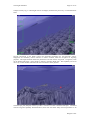
This project produced a generic 3Dvisualisation engine, known as 'Flight'.
Flight is a compact, flexible, general
simulator that can run on standard PCs
and will be useful in educational
and research environments.
The
simulator supports force feedback
effects through a compatible joystick,
and makes use of advanced 3D
graphics hardware where available.
The system is extremely configurable
on two levels. At the normal userlevel, the system can be configured
with a task language, with which users
can select maps, vehicles, tasks, force
feedback effects and how they all
interact with each other. A developer can create new components, and add them to the simulation.
They would then be available to normal users within their task language definitions.
Although the name 'Flight' implies that the simulation is designed with only airborne vehicles in mind,
this is in fact not true. The simulation can be used to visualise any object, and is already being used in
several areas within Glasgow University.
The
Department
of
Mechanical
Engineering are currently using a version
of the system (known as the 'ME Build')
to visualise trucks rolling over when
trying to turn at excessive speeds. A
component representing a truck was
simply added to the system, and data
produced by another simulator (written
by Daimler-Benz) is fed into the 'Flight'
program. Users at the department can
then watch a visualisation of the raw data
in full 3D. This project is described in
depth in the chapter Case Study - The
ME Build.
Mobile phones are also being modelled using the system. Researchers in the Computing Department of
the University wish to investigate how users can communicate with their phones through gesturing,
Douglas Currie
The 'Flight' Simulator
Page 9 of 117
instead of conventional keypads and buttons. For example, to answer a phone call a mobile phone user
could simply shake the phone in a specific way, rather than have to find and press a small key on the
handset. Data generated through other methods can be fed into the system, and another component
representing a mobile phone added to the simulator. These gestures could then be visualised.
Another use of the system is
experimentation with force feedback
effects, in order to provide useful data to
a user. In particular, the model of a
helicopter was created, with a simplified
(but still complex) simulation algorithm
and functional Heads Up Display.
Different force feedback effects and
degrees of computer automation can be
modelled, and the task language
mentioned above allows a user to set up
tests in order to evaluate specific
methods or effects.
The
Department
of
Aerospace
Engineering are also interested in the
simulation, as it can be used to model
different aircraft designs, and to test their handling characteristics and performance. Students can
experiment with particular points of a design, and see the resulting behaviour of the aircraft in full 3D.
They are also interested in the force feedback capabilities of the system, which can be used to both
augment a pilot's control inputs and increase the pilot's situational awareness. For example, control
augmentation could be used to help the pilot locate a landing platform or waypoint in heavy fog.
Military vehicles could use force feedback techniques to provide threat information directly to the pilot,
as he would not have move his eyes from the HUD in order to focus them on a threat display.
1.3 Motivation
Computer simulations have been in existence almost since the invention of the computer itself. In the
1940s, early computers were being used to simulate the trajectory of artillery shells for naval vessels,
and the interaction of atoms during the development of the atomic bomb. Although the processing
power available to these early systems was minuscule compared to today's home computer systems, the
results of these and many other simulations have been of great use to researchers, designers and the
population at large.
In recent years, computer technology has advanced far enough to allow simulations to be built with
which real-time human interaction is possible. Aviation companies, NASA, the military and many
other groups routinely use simulators as testing beds for new designs, or simply as training utilities.
Some companies have even produced simulations for the public, designed around many commercial or
military vehicles. The recent widespread availability of advanced graphical hardware has allowed the
full three-dimensional visualisation of these simulations with increasing reality.
However, these simulations are usually specific to one vehicle, or group of vehicles (for example,
aircraft). If a new entity is to be modelled (for example, a submarine), more often than not an existing
simulator is re-written. It would be useful to allow a system developer to simply create a component
encapsulating the characteristics of the new entity, and present this to the simulation system. This
would allow the simulation to visualise many different vehicles, and more easily allow comparisons of
these vehicles.
As an example, consider altering the engine specifications of a helicopter. The revised model of the
helicopter could be presented to the simulation, and a user could then compare the flight characteristics
of this new model with the previous version, perhaps even visualising both simultaneously. (McRuer,
1990) discuss the operator-vehicle control theory, which attempts to model this interaction.
In addition, the tasks which current simulations set for a user are usually very specific to the
simulation's application domain. Again, to alter these tasks or create new ones, the simulation is quite
often re-written. The actual set of tasks is usually hard-coded into the program, letting the user select
from a pre-defined list of tasks. To allow more flexibility, it would be useful to allow a user to
Douglas Currie
The 'Flight' Simulator
Page 10 of 117
dynamically configure the tasks for a specific purpose. Further, a system developer could create new
tasks and easily plug them into the system, making them available for normal users.
One new technology which has become available recently is
Microsoft's DirectInput API (Application Programmer's Interface),
part of the DirectX API. This set of libraries allows force-feedback
effects to be sent to a joystick; these effects can override or augment a
user's input. (Grigore, 1996) provides a good background of the
theory and applications of this technology. Many current vehicular
control systems provide some sort of computer assistance (e.g. fly-bywire aircraft), which monitors the inputs of a human controller, and
alters them (if necessary) depending on the current state of the
vehicle. This augmentation is performed between the human input
and the resulting mechanical actions of the vehicle, as described by
(KrishnaKumar, et al, 1994). Using force feedback, this augmentation
can be applied directly to the control column. The computer could
then help a novice pilot perform certain manoeuvres, and as the pilot becomes more able this
augmentation can be gradually reduced.
The technique could be used to provide the user with more feedback on the current state of the
simulation, or more precisely, the user's vehicle within the simulation. Current simulations have
utilised this technology, but again the effects are hard-coded. It would be advantageous to allow a
system developer to configure new force feedback effects, perhaps designed for a specific vehicle and
task. Different methods of providing these effects would allow vehicle designers to compare different
force feedback effects, and their usefulness.
As an example, consider a helicopter attempting to land on a helicopter pad (or helipad). One such
effect could be designed which nudges the user's joystick in the direction of the helipad every second.
A comparison could then be made of a user's performance with and without the effect enabled. Such a
system would allow rapid development of and experimentation with new feedback techniques.
1.4 Overview
With the above observations in mind, this project will focus on the design and production of a
simulation. A generic 3D-visualisation engine will be produced, tailored but not limited to the
simulation of user-controlled entities. The simulation will support force feedback effects, and will
provide the ability to create user-defined tasks. A developer will have the ability to easily add new
components such as maps, vehicles, tasks, and force feedback effects.
Such a system has many possibilities. It can be used to visualise almost any physical entity, if the 3D
model can be created by the developer (more an issue of time than ability), and can, depending on the
underlying model, simulate the physical characteristics of the entity with differing degrees of accuracy.
Indeed, different models of the same physical entity could be created and their characteristics (e.g.
turning rate or velocity) compared. Although the helicopter is used extensively in this report to
illustrate concepts, the simulation can be configured to model any entity, be it vehicle or some other
object.
Similarly, different force feedback effects could be designed, compared and refined, and perhaps
eventually used to produce useful experimental data for use in an actual production vehicle. The firing
of these effects can also be defined, allowing experimentation with different degrees of computer
automation.
The ability to create and modify tasks would allow the tailoring of these tasks to suit specific entities,
in order to evaluate their specific characteristics. For example, hovering is a task really only applicable
to a helicopter, whereas parking would apply to several types of entities. A newly created vehicle
component may require specific tasks in order to measure its performance.
Further, although the system will have six primary visualisation dimensions (three positional values
and three orientation values), it can theoretically visualise data with any number of dimensions. As an
example, take the case of seven dimensional data. Six of these dimensions could be mapped to the
position and orientation of each entity, and the seventh could be mapped to some internal state of the
entity, such as its colour or size. By adding pieces of state to a model and defining how the state is
represented, data of any dimension can be visualised. Further, the nature of the simulation makes it
extremely appropriate for visualising time-dependent data, and the entities can alter their appearance
and position/orientation with time, depending on the data provided by the user.
Douglas Currie
The 'Flight' Simulator
Page 11 of 117
1.5 Preliminaries
In order to understand fully the content of the project and this documentation, the reader should be
familiar with several techniques and technologies. Although the rationale for the choice of
technologies is detailed in the Architectural Design, they will be briefly described here. The reader
should be familiar with
Object-Oriented Design and Methodology
The proposed system will be extremely complex and modern design and implementation
techniques will be required in order to manage its construction. It would be advantageous for
the reader to have some background in OO design and implementation in a language such as
C++, Smalltalk or Java. Knowledge of software engineering processes (such as the 'waterfall'
model) and principles (such as 'encapsulation') would be valuable.
DirectX and DirectInput
The requirement for force feedback immediately implies the use of Microsoft's DirectInput
API, part of the high-performance DirectX API. This further constrains the choice of system
platform and implementation language.
Visual C++ 6.0
The majority of the code will be written in Microsoft Visual C++ 6.0. This language is far
more complex than Java and the original C language, and many of its advanced features will
be utilised in the implementation of the system.
OpenGL
Silicon Graphics Inc.'s proprietary high-performance graphics API will be employed to model
and render the 3D-visualisation. Although several advanced features of the API are employed,
their use is similar to most 3D graphical APIs, and knowledge of any of these (e.g. Direct3D)
would be invaluable.
Visual Basic 6.0
This rapid application development tool will be used to construct utility modules within the
system. It is extremely simple and no special knowledge is necessary
Java 1.2
A component of the system will be written in Sun's portable Java language.
knowledge of any object-oriented language would be valuable.
Again,
As is apparent from the above discussion, an element of design, and even implementation, must be
considered even before requirements elicitation can begin as the definition of the project immediately
constrains some of the technological options available.
1.5.1
Definition of Terms
Several terms are used extensively throughout the documentation (and indeed the source code).
Although they will be explained more fully in the coming sections, they are outlined quickly below.
Control
A Control is simply another name for any entity to be modelled by the simulation, such as a helicopter
or car. They are so named because they will be controlled in the simulation, either by the pilot, or by
some other algorithm (such as a pre-recorded simulation, or an inverse-simulation algorithm
[automated control algorithm where the required control inputs are calculated mathematically]).
Douglas Currie
The 'Flight' Simulator
Page 12 of 117
Directive
A Directive is the assignment of a specific action to the user. An example could be a landing directive,
where the user must apply inputs to their Control to land it at a particular location.
Task
A Task is the collective name for a set of Directives. To complete a Task, its Directives must be
accomplished in order.
Inverse Simulation
Inverse simulation techniques are computational methods that determine the control inputs to a
dynamic system that produce desired system outputs. This technique is discussed by (Hess, et al, 1991)
and (Rutherford, et al, 1996).
1.6 Project Software Engineering Process and Report Outline
The remainder of the report follows the design and implementation process followed during the
construction of the final system. The software process used was akin to that of the standard 'waterfall'
model, with similarities to Boehm's 'spiral' model. Each stage normally has a planning phase, where it
is detailed in full. At any point in the design and implementation cycle, the process may return to the
initial requirements specification, in order to add or amend a feature missed during previous cycles.
Initially, the requirements specification is performed, where the high-level requirements of the system
as a whole are laid out.
The initial risk analysis serves to identify any risks to the project which are immediately apparent
from this high-level review of the system. Where possible, measures taken to mitigate these risks are
outlined.
The architectural design results in a modularised definition of the system, and the interfaces between
these modules. Although the data formats passed between the modules are not yet known, the
messages to be passed are known from the requirements specification.
The requirements definition sets out in detail the required functionality of each component in the
system.
Further risk analysis then updates the project risks, adding those that are specific to each component's
design and/or implementation. Details of this phase can be found in the Risk Analysis Document.
A process similar to that used for the entire project then begins for each component. The component
design stage takes the requirements found during requirements definition and applies the design cycle
to each component in turn, possibly including (dependent on complexity) structural specification, subcomponent definition, interface specification and dataflow analysis.
A further stage of risk development is then completed, which amends those risks identified previously,
and adds any found during the design of the system components. Again, details of this phase can be
found in the Risk Analysis Document.
At this point, the implementation of a prototype (and eventually the final version) of each component
can be constructed. Interesting points about each component's implementation are detailed in this
section.
Unit testing is then performed on each component, where implementation errors are corrected if
possible. Often, however, the process must return to the initial requirements specification, or at least
the component design stage. The above stages are repeated until the requirements specification,
requirements definition, system component design and the actual system are in agreement.
Integration and system testing is then concerned with testing the system as a whole, and may require
the process to return to a previous stage.
After system testing, the design and implementation of the system is essentially complete, and the
system status is described in full.
The report then outlines how a developer could extend the simulator to include new Controls, maps
and other items.
Douglas Currie
The 'Flight' Simulator
Page 13 of 117
A case study is then described, in which the Mechanical Engineering department of Glasgow
University used the system to model a truck and create visualisations of trucks overturning when
corning at excessive speeds.
Finally, the project is evaluated as a whole, considering the design and quality of the system.
Douglas Currie
The 'Flight' Simulator
Page 14 of 117
2 Requirements Specification
2.1 Requirements Plan
The first stage in the project was requirements specification. The aim of this stage was to determine
the required functionality of the system as a whole, including its interaction with external entities (files
and human users, etc.).
In order to determine this functionality, the continual process of requirements elicitation was performed
throughout the project. Indeed, many of the system's requirements were not determined until late in the
project, after prototypes were available for demonstration and comment.
The majority of the requirements were derived through discussion with the project supervisor, Dr
Roderick Murray-Smith, currently at the University of Glasgow. Others were found after comments on
prototypes from the Mechanical Engineering department of Glasgow University, the Aerospace
Engineering department at Glasgow University, the GIST group at Glasgow University, and colleagues
of the project supervisor who were involved in similar projects or could be potential users of the
system.
After requirements have been found, they must be analysed to determine their importance and
estimated difficulty of implementation. They are then grouped into logical sets, and used as the basis
for the Architectural Design stage.
Note that although the requirements were discovered at various points during execution of the project,
to save time and space they are presented in this document in their final form. This section provides a
brief overview of the system requirements. Full details can be found in Appendix A - Requirements
Specification Document.
2.2 Project Description
The ultimate goal of the project is to produce a generic 3D-visualisation engine, capable of force
feedback. Much of the simulation should be user-configurable, with available options including
Controls, terrain, Tasks, and force feedback effects.
The simulation will centre around a main Control, which the human user may or may not directly
control, depending on the Task with which the user configures the simulation.
2.3 User Definitions
The system has two potential groups of users, which will be defined below. This distinction will be
made throughout the requirements/design stages, and indeed in the remainder of the report.
2.3.1 Users
Users of the system are concerned with configuring the existing components of the system in order to
model specific scenarios. An example would be setting up a Task to time how fast a human pilot can
fly through a waypoint course, and then using different helicopter models to examine the differences
between their handling characteristics.
A user will normally only be concerned with the executables comprising the system, and will not
normally require access to the design documents or source code.
Douglas Currie
The 'Flight' Simulator
Page 15 of 117
2.3.2 Developers
Developers of the system will be concerned with making additions to the program. These additions
could be in the form of new Controls, new Directives, new force feedback effects, etc. Developers will
require access to the design documents and source code, as new executables must be produced to
integrate their additions.
Note that a developer will normally also be a regular user.
2.4 User Requirements
The user will be concerned with two main actions, creating a task and actually performing the
simulation run of that task. There will be the notion of a 'main' Control, which is the Control on which
the simulation will focus, and over which the user has control (if requested) via the joystick.
In the case of creating a task, the user will require the ability to configure many aspects of the
simulation in order that specific entities and/or events can be visualised. The user will create a file
specifying this configuration.
The user should have the ability to select the terrain to be visualised in the simulation, and any
waypoints (which will be signified with a marker).
The user should also have the ability to select the Controls to be included in the simulation, their type
and other properties. These properties include whether the Control leaves a marker trail, where its
input data comes from (the joystick or a previous simulation run recorded to a file), its starting location,
and in the case of the main Control, if its state should be recorded to a file for later replay.
The user should have the ability to select a set of Directives from those already defined, and place them
in a certain order. Each Directive must be accomplished in turn, in order to complete the simulation.
For each directive, the user will have the ability to select its type, whether force feedback effects should
be enabled during its execution, and add any other parameters that the Directive requires. The author
of the Directive (see Developer Requirements) will document these extra parameters.
If a task has been incorrectly specified, the user should be informed of the approximate location of the
error in the task file.
In the second case, that of actually performing a simulation run, the simulation will read a task from a
location specified by the user, and will configure itself as specified in the task file. While the
simulation is running, the user should have the ability to alter its graphical settings in order to increase
the frame rate.
If joystick input has been requested, applying inputs to the joystick will cause the main Control to
respond to these inputs as documented by the Control's author (see Developer requirements).
The user should be able to toggle between an internal and external view of the main Control. In the
external view, the user should have the ability to rotate and zoom the camera lens.
The user will have the ability to pause, rewind and fast-forward the simulation. Depending on the
construction of each Control, it may or may not be affected by this request.
The user will have the ability to exit the simulation at any time.
The user should be able to graphically view the output of a recorded simulation run.
2.5 Developer Requirements
A developer for the system should be able to add his/her own 'splash screen' (introductory screen) for
the system. This is intended to reflect the status of the users or developers of a developed version of
the system. (For example, the University may wish to show its logo on all copies of the system present
in its departments.)
The developer should be able to create new:
Controls, including components to allow new input methods (such as networking
interfaces or inverse simulation algorithms).
force feedback effects and the conditions under which they are fired.
Directives, specifically the conditions under which the Directive is satisfied.
Douglas Currie
The 'Flight' Simulator
Page 16 of 117
Maps, including the position and appearance of each point in the terrain.
structures such as buildings and runways.
Any addition to the system should be well documented by the author(s) of the new component, in a
fashion similar to that presented in the appendices of this report.
2.6 Non-Functional Requirements
The system will run on portable computers possessing a Pentium II processor of speeds over 300 MHz.
The system will run under the Microsoft Windows 9x/2000 operating system, with full utilisation of 3D
hardware where possible. This 3D hardware must be fully OpenGL compatible and have a full
OpenGL ICD (Independent Control Driver). If possible, this ICD should be certified by Microsoft.
Where compliant 3D hardware is not available, the Windows operating system will emulate it in
software. However, performance will be severely degraded and graphical detail may need to be
reduced in order to keep the frame rate acceptable. The simulation should run at a frame rate of 10+
frames per second, in order to allow acceptable human interaction.
An installation of DirectX 6.0 or later is required, in order to support the force feedback effects.
The system should run on computers with 64 megabytes of memory or greater, and should use minimal
hard disk space (less than 1 megabyte, excluding recorded simulation runs).
Any joystick attached to the simulation should have four axes and a POV (Point-Of-View) or 'hat'
switch. If the user requires force feedback, the joystick should support this technology. If the joystick
has no force feedback capability, the simulation will run as expected, but without the force feedback
effects. If no compatible joystick is attached to the computer, the user will not be able to directly
interact with the simulation, except via options keys to alter graphical settings, etc. In this case, the
user may not select joystick control as the main Control input method.
Several documents should be produced. These are listed in the full Requirements Specification
Document, and include manuals for both users and developers. Two distributions of the system are
also required.
Under exceptional conditions, such as memory exhaustion, the system should attempt a graceful shut
down.
3 Risk Analysis
Risk planning should play an important part in any software engineering process. Due to the nature of
the project (the author has never before used the OpenGL or DirectX APIs, and has never used
Microsoft Visual C++ 6.0), risk analysis and planning was considered a serious part of the project.
After each major requirements or design stage, the risks to the project were assessed, and where
possible, methods to mitigate these risks were devised.
The details of the risk analysis are fully described in the Risk Analysis Document in the appendices.
This analysis was performed in three phases. The first was performed after the initial Requirements
Specification, and examined the high-level risks to the project. The second phase was performed after
the detailed Requirements Definition, and investigated specific risks in more detail. The last phase was
performed after design and before the implementation phase. Here, risks specific to implementation
matters were examined.
This risk document was monitored to ensure the project did not meet with unexpected problems, and it
also played an important role during design and implementation decisions. It determined the order of
component design and implementation, as the most demanding tasks could be identified and attempted
first.
Douglas Currie
The 'Flight' Simulator
Page 17 of 117
4 Architectural Design
4.1 Structural Analysis
The architectural analysis stage will split the system into its constituent entities. Such an entity will be
a file or set of files, a database, or a process. The functions of the entities can then be specified, and the
interfaces between the entities defined.
At this stage, the design is still extremely high level, and although the formats of the messages between
components are yet to be defined, the messages passed between them and the mechanism by which
they are passed can be ascertained at this stage.
Although the architectural design is an iterative process, only the final design is presented here. A brief
overview of each component is presented. For a full description of each component, and the definitions
of the interfaces between them, see the Architectural Design Document.
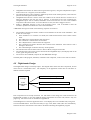
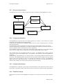
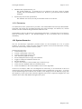
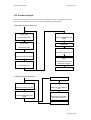
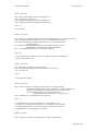
4.2 Structural Specification
The structure diagram below shows the run-time organisation of the system.
loader programs, selected at
runtime - one of:
FlightLoader
(GUI)
EDSSplash
FlightBrowser
FlightLink
Flight
FlightLdr (character based)
task files
log files
This system structure is composed of eight main components, two of which are file stores. One of
these file stores will hold the task files, the other will hold log files. Log files will hold the record of a
simulation run, and will be created on request from the user (configured in the task file).
The other six components are processes and will be briefly described. The implementation language of
each component is mentioned, and a full rationale for this decision can be found in the Architectural
Design Document.
A loader program will be used as the front end of the system. This program will let the user select the
task file with which the simulation will be configured. Two loader programs will be created.
FlightLoader will be written using Visual Basic and will present a graphical user interface (GUI) to the
user. This program will also allow the simple editing of task files. For technical reasons described in
the Architectural Design Document, a small utility program, FlightLink (written in Visual C++) is
required to launch the 'splash screen' and the actual simulation.
The second loader program will be written in Visual C++ and provide a text-based interface for use on
those machines which do not have Visual Basic runtime support installed.
Douglas Currie
The 'Flight' Simulator
Page 18 of 117
The EDSSplash process (the author's 'splash screen') will be written in C++ using the OpenGL API to
create a 3D introduction screen. The FlightLdr or FlightLink process will activate this process just
before the actual simulation is activated.
Flight is the main process, and will be written in Visual C++, using the OpenGL API for the graphics
and the DirectInput API for the force feedback.
FlightBrowser will be written in Java, and will allow a user to 'browse' the record of a simulation run.
Douglas Currie
The 'Flight' Simulator
Page 19 of 117
5 Requirements Definition
The Requirements Specification Document (Appendix A) details the high-level requirements of the
system as a whole. The Architectural Design Document (Appendix C) shows the high-level design of
the Flight system, giving an overview of its constituent parts. The requirements definition stage of the
project takes these high level requirements, and distributes them to the necessary components of the
system. Each component is then examined in greater detail, and requirements may be added or refined.
After this process each component should have a set of requirements, which it must fulfil in order to
satisfy those described in the Requirements Specification document. (Note that some requirements
from the requirements specification will not appear here. For example, the need for an introduction
screen resulted in the EDSSplash component, but will not result in any further requirements. Note also
that the Flight Task Language absorbs many requirements.)
This section gives a brief overview of the requirements of each component in the system. The
Requirements Definition Document (see Appendix D) provides full descriptions of these requirements.
Note that these requirements were discovered at various stages of the project. As new functionality
was required, the Requirements Specification and Architectural Design Documents were updated, and
then the Requirements Definition was performed again, distributing the requirement to the relevant
component (or components). To save time and space, however, the requirements are given here in their
final form.
5.1 Flight Requirements
The Flight process is the main component of the Flight system, and actually performs the simulation.
When launched, the program should configure itself with a task selected by the user. The name of this
task will be extracted from the 'task.ini' file.
The user should be able to exit the simulation at any time. Control over the graphical settings of the
simulation should be available, along with control over an external view and its position. The program
should also allow the user to rewind, pause, and fast-forward any Controls which are reading their state
from disk.
The simulation itself should provide support for particles (such as smoke), structures, terrain, fogging,
force feedback effects, and graphical models of the Controls.
During the simulation, the joystick should operate as documented by the author of the main Control.
No concrete requirements can be formed here, but descriptions of the standard Controls are available in
Appendix K.
5.2 FlightLoader Requirements
The FlightLoader component will be a Visual Basic program, providing a graphical user interface to
the system. The program should display a list of available tasks, and a method should be provided
whereby the user can refresh this list (in order to include task files added while the program is running).
The user should be able to perform simple editing of task files, as well as copying, renaming and
deleting these task files. The user should have the ability to view the 'trace.log' file from a previous
simulation run.
The user should be able to initiate the simulation, after choosing a task to perform. In this case, the
program should write the name of the selected task to the 'task.ini' file, before launching the FlightLink
program. This program will synchronously launch the EDSSplash process, followed by the main Flight
simulation process. During this time, the FlightLoader program will continue to operate.
The program should terminate on request from the user.
5.3 FlightLdr Requirements
The FlightLdr component will be a simple loader program, used as a front end to the Flight system on
machines without Visual Basic runtime support. The program should display a list of tasks available to
Douglas Currie
The 'Flight' Simulator
Page 20 of 117
the user. If the user makes an invalid selection, the program should exit. If the user makes a valid task
selection, the program should write the name of the task to the 'task.ini' file, before launching the main
Flight simulation process. While this process is active, the FlightLdr program should be suspended.
After the Flight process terminates, the FlightLdr program will reactivate, and will display the task list
again, ready for another selection from the user.
5.4 EDSSplash Requirements
The EDSSplash component should provide a simple introduction screen, to be run before the Flight
simulation component. It has no real requirements, other than terminating after a finite amount of time,
or after the user has pressed a key on the keyboard.
5.5 FlightBrowser Requirements
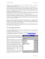
The FlightBrowser program will allow users to graphically view the contents of a log file. The user
should be able to select a log file, and the program will load its contents into memory. Two modes
should be provided, allowing the user to view the graphs of any selected variables on the same set of
axes, or two selected variables plotted on Cartesian axes.
The user should be able to select different colours for each variable and the axes, and should be able to
request information on the log file, such as the number of readings, the range of each variable, and the
values of each variable at selected points in the log.
The user may select a new log file or terminate the program at any time.
Douglas Currie
The 'Flight' Simulator
Page 21 of 117
6 Component Design
6.1 Design Plan and Implementation Considerations
This section describes the design of each of the main components in the Flight system. Being one of
the major phases of the project, the design is documented here in full. The components, Flight,
FlightLoader, FlightLdr, EDSSplash and FlightBrowser, are referred to as processes, and each will
have its own components. This design phase aims to determine these components and their structure.
During the architectural analysis phase for the entire project, the implementation languages of each
process were chosen. This knowledge could be used during design, making use of any special
mechanisms available. Also, the risk analysis performed earlier allowed the most challenging
processes to be designed first. The experience gained from these designs reduced the effort required
for subsequent processes.
For each component, an architectural analysis phase is performed, similar to the system architectural
analysis performed earlier in the project. The resulting components are then described, and the
interfaces between them are defined. Finally, a dataflow analysis of the complete process describes
how control and data will flow through the system. Note that the complexity of each stage will depend
on the process under design. For example, the EDSSplash design phase was extremely short, whereas
the main Flight process took considerable time and effort to design.
Although the design phase is an iterative process, and frequently required alteration (due to new
requirements), the designs are presented here in their final form.
6.2 Flight Task Language Design
The Flight Task Language was the first component of the system to be designed. Although no
requirements definition was performed for FTL, its requirements can be taken from the initial
requirements specification. The Flight Task Language will define everything that the Flight system can
possibly do, and so must satisfy the entire set of User Task Requirements (listed in the Requirements
Specification Document).
The reader is referred to Appendix G for the full design of FTL. Once the language was defined, there
existed a concrete description of the required functionality of the simulation. Any changes or additions
to requirements usually resulted in an alteration of the FTL specification. Modifications to the system
design and/or implementation cascaded from this specification.
6.3 Flight Logs Design
Although not a complex (or at this stage important) component, the design of the log files was
performed after the FTL specification. This allowed the design of the main Flight process to proceed
with some knowledge of the data required by a Control.
The format of a log file was defined as follows:
First line is preamble (e.g. source of data file)
Second line preamble (e.g. author of the Control who logged the data)
Third line should hold the date and time (e.g. ‘14 30 1 1 00’ for 14:30 on the first of Jan, 2000)
Fourth line should hold the names of the data variables, separated by spaces
Lines five to the end hold the data values in the same order as line 4, separated spaces
This simple design meant that the relevant components of the Flight process would be relatively
simple. It also increased the chances that data files produced through other means would require little
modification before being compatible with the program.
Douglas Currie
The 'Flight' Simulator
Page 22 of 117
6.4 Flight Design
The Flight design was the first major process of the system to be designed. As the process was rather
complex, the full design process was performed, beginning with an architectural analysis. The
functionality of each component was then defined, followed by the interfaces between them. Dataflow
analysis was then performed, in order to check the correctness of the design and show how control and
data flow through the process.
The design was simplified with the knowledge that the process would be single-threaded. No
concurrency considerations would have to be taken into account, and the process could assume solitary
access to all its data structures, operating system resources (such as window device contexts) and
hardware resources (such as the 3D-hardware graphics device context).
The design was constrained by the requirements laid down by both the Requirements Definition
Document and the functionality presented to the user through FTL.
The implementation language selected was Visual C++, using the OpenGL API for 3D graphics and
the DirectInput API for force feedback effects. The win32 API would be used for 2D drawing (this is
faster than standard C graphics libraries). The individual mechanisms offered by each technology both
limited and extended the available design options, and the final designs were selected because of their
elegance or efficiency.
Many interesting design patterns were used during the design of the Flight program, and these are
documented during the descriptions of the relevant components, below. (A design pattern is a standard
way of solving a particular design or implementation problem. (Gamma, et al, 1999) describe many
common design patterns.)
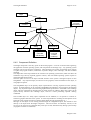
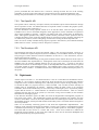
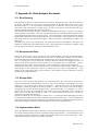
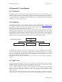
6.4.1 Structural Specification
The runtime organisation of the main components of the system is shown in the diagram on the next
page. The diagram shows the main objects in the system, and their runtime references to each other.
There is only one instance of each object in the system, except where denoted by multiple boxes. Note
that for clarity, only the major components and references are shown. Many of the components will
directly or indirectly reference each other, and when two component wish to communicate they will
normally do so directly through pointers stored in member variables. This has both drawbacks and
advantages.
The drawback is that this greatly increases the coupling of the design. However, through the use of the
object-oriented principle of encapsulation, an object's interface to the rest of the system can be defined,
and any changes to the actual object implementation will not affect the rest of the system in any way.
Allowing objects to reference each other directly has several advantages. The most obvious of these is
efficiency, and this is even more relevant in object-oriented programming languages like C++.
Following a trail of pointers through function calls in order to acquire a pointer to a specific object is
very inefficient, as each function call (which will serve only to return 32 bits of data) may require the
creation of a stack frame, register-memory traffic, and several other performance penalties. By
ensuring that each pointer is valid before its use, the safety provided by these function calls can be
achieved, with a large increase in performance.
The program will operate in three phases. The first, startup, will read the user's chosen task file, and
configure the system with the objects required for the simulation. The second phase, the actual
simulation, will operate as a loop, repeatedly updating the state of the objects and then rendering a 3Dvisualisation. The final phase, shutdown, will cleanly release the resources acquired during the startup
phase.
The next section will describe each component in turn, including important associations not shown in
the diagram.
Douglas Currie
The 'Flight' Simulator
Page 23 of 117
Flight
CFlightPack
CStructure
(concrete
subclasses)
CToolkit
CFlightData
CTask
CParticleEngine
CMap
CVehicleList
CWayPointList
CMapGenerator
(concrete
subclasses)
CControl
(concrete
Control
modules)
CStrucList
6.4.2 Component Definition
The Flight component is the entry point for the actual program. It will be concerned with registering
the application with the operating system, and will perform the message loop. Any operating system
messages will be received at this component. These messages will consist of keyboard input, requests
to repaint the program window, notifications of palette changes, timer interrupts, and other standard
messages.
The component will be responsible for the creation of an operating system timer (which will drive the
simulation loop) and any required graphics contexts, and will handle operating system requests to
repaint the application window.
The main point of access to the object-oriented structure of the system is through an object of class
CFlightPack. Any keyboard input (of relevance to the program) will be forwarded to this object, as
will graphical requests.
The CFlightPack object is the primary object responsible for receiving requests from the operating
system. It holds references to the CToolkit, CFlightData and CSettings (not pictured in the diagram)
objects. Any keyboard input concerned with graphical detail preferences is forwarded to the CSettings
object, which is responsible for keeping track of which options are enabled. Many other objects in the
system directly reference this CSettings object, and use it while performing OpenGL drawing
commands.
The CToolkit object is a utility object responsible for all standard (i.e. not specific to Controls or
structures) graphics functions in the system. It will be responsible for rendering the 3D OpenGL scene
and some win32 graphics functions to display details about the task (elapsed time, etc.).
Messages to this object are not usually passed through the CFlightPack object, but instead are sent
directly to the object from the Flight component. This will be done for efficiency reasons, as the
services in the class will be requested many times per second, and numerously during system startup
(as graphics contexts are initialised).
Douglas Currie
The 'Flight' Simulator
Page 24 of 117
The CFlightData object will hold the majority of the simulation data, and is the central object in the
system. Once every simulation loop, this object will be responsible for updating the state of the
simulation as a whole, using the objects it references. Data required by the CToolkit (for rendering the
3D scene) will normally be acquired directly, by retrieving pointers from this CFlightData object.
Amongst such data required by the toolkit is the CExternalView object (not shown on the diagram).
This object holds the current settings for the external view, and is made available to the main Control
module (see below).
The CTask object is created during startup by the CFlightData object. It reads the 'task.ini' file for the
name of the user's selected task, then reads the task file. The CTask object understands FTL, and every
Control module, structure, map and Directive available in the system is registered with it. While
reading the task file, the CTask object selects the relevant components, and passes them back to the
CFlightData object for the simulation phase. If there is an error in the task specification, the CTask
object simply creates default components (so that the system can be shut down cleanly) and posts a quit
message to the operating system. It also leaves an indication of the error location in the 'trace.log' file.
While creating the Control modules, CControlData objects (not shown in the diagram) are used to
encapsulate the configurations specified in the task file.
The CTask object will be responsible for monitoring the condition of the current Directive (if there is
one), and will be periodically asked by the CFlightData object for the status of the task. It will also
send details of the Directive to the main Control (these details are used to configure force feedback
effects). The internal details of tasks will be held in tagDirective structures (not shown in the diagram),
and the information passed to the Control will be encapsulated in a tagFFInfo structure (again, not
shown in the diagram). This class will require modification if new Directives are to be added by a
developer.
This object uses the Factory design pattern, where it is responsible for creating the specific components
required by the rest of the system. It actually contains multiple factories, each creating components
tailored to the requirements set out in the task specification.
The CParticleEngine object will encapsulate a particle engine capable of tracking smoke particles,
generated by smoke emitters (on structures) or Controls. The details of each smoke particle will be
held in a tagParticle structure (not shown on the diagram), and the details of the smoke emitters will be
held in tagPEmitter structures (again, not shown). This object will receive notification to update itself
from the CFlightData object, once each loop through the simulation. The CToolkit will also send
notifications to the particle engine to draw itself, using the OpenGL API. On this notification, the
object will render each smoke particle it holds details on.
The singleton design pattern was used in the design of this component, and is evident in its
implementation. The class itself will ensure there is only one access point to its services. Although
most components in the system have only one instance, this was an experiment in using different
programming styles.
The CWayPointList will hold the details of each waypoint declared in the task specification, in a
tagWP structure (not shown on the diagram). The CToolkit will notify the CWayPointList object to
draw its waypoints, and it will provide the CFlightData and CTask objects with accessor functions to
obtain the details of a waypoint.
This list object will be created by the CTask and passed to the CFlightData object.
A Control module will encapsulate a Control, and will contain four classes. These classes must extend
from four abstract classes, CControl, CDataStreamer, CDataLogger and CDIData. A concrete
implementation of a Control module will model a specific entity, such as a helicopter or aeroplane, and
new Control modules can be added to the system. The CTask object will create the main Control
depending on the task specification, and may select from those Controls which have been registered
with it. There will be one set of Control modules for each Control declared in the task specification
(including the main Control).
Each class provides some functionality of the module, and together they communicate with the rest of
the system.
The subclass of CControl will contain the simulation algorithm (such as helicopter or aeroplane
dynamics) and a graphical model, along with other functions, which will help to describe the Control to
the rest of the system. The HUD of a Control will also be defined in this class. The CControl object
will use an object of class CJoystickData (not shown on the diagram) to read the state of the joystick.
Douglas Currie
The 'Flight' Simulator
Page 25 of 117
The CDIData subclass will encapsulate the force feedback effects supported by the Control. These will
be defined specifically for each Directive, and new effects can be added by modifying this class. The
design will also allow the creation of effects that can be fired from the main CControl class (for
example, during the simulation algorithm).
The CDataStreamer subclass will be responsible for logging the state of the Control to a file, if
requested in the task specification.
The CDataLogger subclass will similarly be responsible for reading the state of the Control from a file.
These four classes will be C++ friend classes, as they are highly dependent on each other. This will
allow more efficient transfer of data between the four.
The Control modules are an example of the template design pattern, using the inheritance mechanism
provided by C++. The superclasses, although never created directly, are created indirectly when a
subclass is instantiated. The superclass takes care of many of the routine functions provided by the
component, providing a template for concrete implementations. Where differences between Controls
are required, the subclass can fill in the functions left out in the template (superclass). Controls can
then be assigned dynamically, and although all are treated identically by the system, they may each
behave completely differently.
Although the CFlightData object holds a reference to the main Control, any other Controls are held in a
CVehicleList object. This list object is created by the CTask object and will be passed the details of
each Control to be created (via a CControlData object). After all Controls have been created (and
references stored in the list), the list will be passed to the CFlightData object.
The list will receive requests to draw itself from the CToolkit object, at which point it will ask each
Control it contains to draw itself. It will also be notified by the CFlightData object to update each of
the Controls it contains. It will also provide accessor functions to other objects, which enable other
parts of the system to enquire about the state of a particular Control.
Structures such as runways and helipads are handled with two design patterns, template and flyweight.
The CStructure class will provide the standard services of a structure. The template design pattern,
through the use of the C++ inheritance mechanism, allows a developer to create a subclass of
CStructure. This subclass can define a graphical model, along with details of any smoke emitters and
landing zones on the structure. These structures can be created dynamically, and will be treated
identically by the system.
The flyweight pattern allows large numbers of a small set of objects to be stored efficiently. This is
convenient in the case of CStructure subclasses, which will hold large amounts of data (in the form of
OpenGL call list data). One prototype copy of each available CStructure subclass is created, and
instead of creating a new object when a structure is required, a pointer to the prototype is created
instead. The details of the structure (including its type, position and orientation) are held in a tagStruc
structure (not shown in the diagram), which will be far smaller than an instance of a CStructure
subclass.
These tagStruc structures are stored in a CStrucList object, which is created by the CFlightData object,
passing a pointer to the prototype structures (also held in the CflightData object) for use in further
drawing operations. The CStrucList will, on notification from the CToolkit, draw each structure using
the details in the tagStruc structures and the associated prototype CStructure subclass objects. The
class will also provide services to check for landing sites, and locations of smoke emitters will be
signalled to the CParticleEngine. The details of each structure are added to the CStrucList during the
map generation, described next.
The CMapGenerator again uses the template design pattern. A concrete implementation will provide
the ability to format the terrain data of a CMap object (described next), and add any required structures
to the CStrucList object. The CTask object creates the map generator according to the task
specification, and passes it back to the CFlightData object. This will then create a CMap object, and
pass it the map generator.
Developers will be able to create new a map terrain by creating a new CMapGenerator subclass and
registering it with the CTask object.
The CMap object is created by the CFlightData object, and is passed a CMapGenerator with which to
format itself. The map object is responsible for rendering the terrain, and checking for ground
collisions with the main Control. It will use the CSettings object during its operation.
Douglas Currie
The 'Flight' Simulator
Page 26 of 117
6.4.3 Interface Specification
The interfaces for each component in the system were defined, after consideration of the services each
component was to offer. These will not be detailed here, and can be found in the source code, in
Appendix M. The interfaces are the public portions of the class declarations, listed in the header file
for each component (documents with '.h' extensions).
The Flight component (entry point of the application) has no header file. However, this component
receives no messages from other components (it only delivers messages to the CFlightPack and
CToolkit objects), only the operating system.
6.4.4 Dataflow Analysis
This section will describe the flow of execution through the system, for each phase of the program. It
also describes the data passed at each step.
The startup phase has the following flow of execution:
Execution enters the Flight component. This creates the CFlightPack object.
The CFlightPack object creates the CToolkit. It then creates the CSettings object, and then creates
the CFlightData object, passing a reference to the CSettings component. At this point, control will
pass to the CFlightData object, but control will eventually return to the CFlightPack module (later
in this sequence).
The CFlightData object first creates the CExternalView object. It then creates the CTask object.
The CTask object creates empty CWayPointList and CVehicleList objects. It then opens the
'task.ini' file and reads the name of the user's selected task from the file. It also opens the
'trace.log' file. At each of the following steps, it writes a 'success' message to the trace log. If any
step fails (due to a badly specified task), the CTask will create default components (to aid a clean
shut down) and write an error message to the trace log.
The CTask reads the preamble, task name and description from the task file.
The CTask reads the main Control details from the task file. It fills a CControlData object with the
relevant data and instantiates the required type of CControl subclass, passing the CControlData
object.
The CControl subclass creates a CJoystickData object. It then formats itself according to the
CControlData object it received on creation. It should create the necessary CDataStreamer and
CDataLogger components.
The CTask object creates the CMapGenerator subclass specified in the task file.
The CTask reads the waypoints from the task file, sending the details of each to the
CWayPointList object.
The CTask reads the details of any other Controls required. For each, a CControlData object is
sent to the CVehicleList object, which creates the correct CControl subclass.
These CControl subclass create CJoystickData objects, along with their own CDataStreamer and
CDataLogger subclasses.
The CTask then reads the Directives from the task file. At this point, the details of the task have
been read, and the main components of the system have been created.
Control then returns to the CFlightData object, which creates a CStrucList object, passing
references to the prototype structures and the CSettings object.
The CFlightData object retrieves the CMapGenerator subclass from the CTask, and creates a new
CMap, providing the map generator, the CSettings and the CStrucList as arguments.
The CMap then uses the generator to format its terrain, and add any required structures. When a
structure is added, its details are sent to the CStrucList object, where landing zones are created and
smoke emitters are registered with the CParticleEngine.
The CFlightData object retrieves the main Control, CWayPointList and CVehicleList objects from
the CTask.
Douglas Currie
The 'Flight' Simulator
Page 27 of 117
Control then returns to the CFlightPack component. This component registers the CFlightData
object it has just created with the CToolkit object.
Control returns to the Flight component, which registers the application with the operating system
and creates a window.
The Flight component asks (via the CFlightPack and CFlightData objects) the main Control to
create its CDIData component. This component creates the necessary DirectInput objects and
defines any required force feedback effects. The Control is also passed a reference to the
CExternalView object.
The CTask then dispatches the force feedback details of the first Directive (or blank details if there
are none) to the CDIData component of the main Control. The CDIData object uses these details
to configure any force feedback effects.
The Flight component then creates the main Windows message loop, which will handle all
messages from the operating system.
Some time later, the Flight component will receive a CREATE message from the operating
system. It will then ask the CToolkit to perform several OpenGL related functions, including
loading any textures, and setting up the device contexts.
The Flight component will then ask the CFlightData object (via the CFlightPack object) to create
the OpenGL models of the structure prototypes and the Controls. Each CStructure and CControl
object will create its own OpenGL model for use by the CToolkit during the rendering process.
Finally, a timer will be set, which will notify the Flight component every 55 milliseconds. This is
the resolution of the standard timer under the Windows operating system. A multimedia timer
could be used, but would use resources (such as CPU cycles) more valuable to the simulation.
After the above sequence of execution, the system then enters the main simulation loop. During this
stage, the program will respond to three types of operating system message. These messages will be
received by the Flight component.
The first is keyboard input from the user. Requests to alter the graphical settings will be sent (via the
CFlightPack object) to the CSettings component. Requests such as pause, fast-forward and rewind will
be sent to the CFlightData object (again via CFlightPack). This object will record the current elapsed
time of the simulation, and will alter it according to the requests. Requests to alter the external view
will be sent (via CFlightPack) to the CExternalView. A request to terminate the program will send a
QUIT message to the operating system.
The other two types of message are the TIMER and REPAINT messages. Their sequence of execution
will be described below.
A TIMER message will result in the following actions:
The Flight component notifies the CFlightPack object that a new simulation step should be
performed. This is forwarded to the CFlightData component.
If the current task has been passed or failed, the message is ignored.
The CFlightData component will first send update messages to each CStructure prototype. This
will allow structures to have state and moving parts.
If joystick input has been specified for the main Control, a message is sent to its CDIData
component. This component checks the Directive details it has (dispatched by the task during
startup, or after the completion of a Directive), and generates any necessary force feedback.
If the task specifies that the main Control should log its state, the CDataLogger component is sent
a message to do so.
Each Control then performs the following actions:
If requested in the task specification, a smoke particle is created (and sent to the
CParticleEngine).
The main simulation algorithm of the Control is performed, in which the Control's state is
updated. This may involve reacting to joystick input or reading data from a file (with the use
of the CDataStreamer component).
CFlightData will then check for a collision between the main Control and the terrain, using the
CMap object, and should flag the task as a failure if a collision is detected.
Next, CFlightData asks the CStrucList object to check if the main Control has landed on a landing
zone. If so, the main Control object is notified.
Douglas Currie
The 'Flight' Simulator
Page 28 of 117
CFlightData then checks the main Control against the waypoints, using the CWayPointList object.
If the Control is at a waypoint, it will be notified.
The CParticleEngine is then notified to update the positions of the smoke particles, and create new
particles from the registered smoke emitters.
CFlightData then asks the CTask to check the condition of the current Directive. If there are no
Directives defined in the task, this step is ignored. If the Directive has been completed, the
CFlightData object will be notified, and details of the next Directive are sent to the CDIData
component of the main Control. If no more Directives exist, the task is flagged a success.
Finally, a REPAINT message is sent to the operating system. This is intended to cause the
window to update itself with the new state of the simulation.
A REPAINT message will result in the following sequence of execution:
The CToolkit component is asked to render a 3D-visualisation of the state of the simulation. This
is done in several steps:
If the simulation is in external view mode, the toolkit should ask the main Control to draw
itself.
The CMap object is then asked to draw the terrain.
The CStrucList is asked to draw the structures.
The CWayPointList is asked to draw the waypoints.
The CVehicleList is asked to draw the other Controls in the simulation. Each control is sent a
message to draw itself.
The CParticleEngine is asked to draw any smoke particles.
The CToolkit then asks the main Control to draw its HUD, using the win32 API.
The CToolkit then retrieves the current status from the CFlightData object, and displays this on the
screen, again using the win32 API.
The screen is then validated, ready for the next REPAINT message.
The third phase of the program, shutdown, will delete each component, in the reverse order of creation.
6.5 FlightLoader Design
The FlightLoader design is extremely simple. The diagram below shows the main components, each of
which will be a Visual Basic form. The simplicity of the application meant that no VB classes or
modules would be required.
frmEdit - simple editing tool
frmFlight
main
application
form
frmRename - dialog to enter a new name
frmTrace - simple viewer for the 'trace.log' file
Each component will be briefly described. For full details of the design, the reader should run the
FlightLoader program (to view the graphical design) and examine the source code, which is only two
pages long. The source code can be found in Appendix M.
The frmFlight form is the main application form. It will display the list of available tasks, along with
several command buttons. It will have the ability to copy a task, delete a task (after user confirmation),
and write the user's selected task to the 'task.ini' file before launching the FlightLink program.
Douglas Currie
The 'Flight' Simulator
Page 29 of 117
The frmEdit form will be launched by frmFlight when the user opts to edit a task. This will be a simple
window with the usual text editing functionality.
The frmRename form will be a simple form to prompt the user for a new name for a task.
The frmTrace form will allow the user to view the 'trace.log' file.
6.6 FlightLdr Design
The FlightLdr component is extremely simple, and the control flow diagram below shows the sequence
of execution.
execution entry
Display task list
[invalid task selceted]
Prompt user for
task
exit
[valid task selected]
Write task name
to 'task.ini'
Launch
EDSSplash
Launch
Flight
6.7 EDSSplash Design
The EDSSplash component also has a very simple design. A cut-down version of the CToolkit
component of Flight will be used to set up the OpenGL device context, and render an animated
OpenGL scene. The program will keep a timer, and will increment it during each animation step.
After a specified number of frames have passed (or the user presses a key), a QUIT message will be
sent to the operating system, causing the program to terminate.
6.8 FlightBrowser Design
The FlightBrowser program will be the second largest component of the system. However, it was
actually the least important, and is not involved actually performing the simulation. It is provided as an
auxiliary tool for the user, and so had the lowest priority during design and implementation.
The full design process was applied to the component, even though it was not complex. Structural
analysis was performed, to identify the required components. The functionality of each of these was
then defined, followed by the interfaces between them. Finally, dataflow analysis was performed to
check that the system would perform if intended function.
Douglas Currie
The 'Flight' Simulator
Page 30 of 117
6.8.1 Structural Specification
The diagram below shows the runtime composition of the components of the FlightBrowser system.
ColorButton
StatsDialog
DataDialog
FlightBrowser
DisplayPanel
LogData
SelectPanel
LogReader
6.8.2 Component Definition
The FlightBrowser component will be the main graphical user interface. It will contain two internal
components, the SelectPanel and the DisplayPanel.
The SelectPanel will hold all the commands available to the user, such as loading log files, or switching
between graph modes.
The DisplayPanel will be responsible for actually drawing and presenting the contents of a log file.
The three components mentioned above will subclass standard UI components provided in the Java 1.2
release (sometimes known as the 'Swing' set of Java components).
The ColorButton component is a utility class, which defines toggle button and a set of colours through
which it can step. Many of these components are used by the main graphical user interface.
The LogData object will encapsulate the data in a log file. A LogReader object is used to read the
contents of a log file into the LogData object. This LogData is then returned to the main FlightBrowser
component.
The StatsDialog and DataDialog are two dialog windows, each presenting different information about
the log file. The StatsDialog dialog will show the user the number of data readings in the log, and the
ranges of each of the variables (as well as the preamble and time/date in the log). The DataDialog
dialog will provide a data browser facility. As the user moves the mouse over the DisplayPanel, the
values of each variable (at the mouse position) will be shown in the dialog.
6.8.3 Interface Specification
The FlightBrowser component is quite simple, and the full details of the component interfaces will not
be given here. Instead, the reader is directed to the source code for the program, found in Appendix M.
6.8.4 Dataflow Analysis
The sequence of execution of the FlightBrowser program is very simple, and will be briefly outlined in
prose.
Douglas Currie
The 'Flight' Simulator
Page 31 of 117
After the program has loaded (or at any time during execution), the user may select to load a new log
file. A LogReader object is created, which will read the contents of the selected log into a LogData
object. This LogData object is returned to the main FlightBrowser component. During this process,
the StatsDialog and DataDialog objects are discarded (if currently active) and default options are
enabled in the SelectPanel.
Options buttons in the SelectPanel (such as colour and selected variables) will affect the graphical
output of the DisplayPanel.
The user (the DataDialog only functions in Graph mode) can select the StatsDialog and DataDialog
options from the SelectPanel, after a log has been loaded. The StatsDialog briefly examines the
LogData object in order to gather the information required for the user. The DataDialog interacts
continually with the LogData object, retrieving the values of each variable as the user moves the
mouse.
Douglas Currie
The 'Flight' Simulator
Page 32 of 117
7 Implementation
7.1 Implementation Plan
After all components were designed, implementation could begin. The order of implementation was
the same as the order of design (of course, minus FTL and the log format). The actual implementations
(source code) can be found in the appendices.
This section describes some of the implementation issues of each component.
7.2 Flight
The main Flight program was written using Visual C++, making use of the OpenGL and DirectInput
APIs.
7.2.1 Visual C++
The program was rather complex, and three options were available for its actual implementation. Each
would affect the ease with which the system could be extended by future developers.
The first option was to create each interchangeable component (such as the Control modules and
Directives) as interpreters. The user would use a specification language (similar to FTL) to actually
configure each component. Adding a new component to the system would then require no change to
the actual code, and the user would only have to write the component specification. An example would
be writing some kind of descriptive language to define a Data Streamer component. A standard Data
Streamer could read this description, and create an object tailored to write the correct data to disk.
However, an early experiment into this method found that under the required load, the program would
be too slow, especially where data streamers/loggers were reading/writing many variables to disk.
Also, the program was required to deal with internal simulation algorithms of any complexity (well,
within reason). Having to interpret potentially very complex mathematical operations (without the
optimisations a compiler would generate) would limit the complexity of all user algorithms. It was
thus decided that all Flight components would be fully compiled before execution.
The second option was to use dynamic linked libraries, or DLLs. Each component of the system (or
group of related components) would be written as a DLL. At runtime, the main Flight sub-component
would find and dynamically load the required DLLs into memory. In order to add a new component,
such as a Control module, the developer would only need to write the C++ code defining the Control
and encapsulate it in a DLL. This could then be picked up by the system, requiring no modification of
the existing code.
However, this approach also had a severe drawback. As the DLLs would be written in isolation from
the rest of the system, major errors (such as missing services) would not be found at compile time, but
would be instead found during runtime. Also, several different developments of the system are
expected. The versioning system used in Microsoft DLLs is rather tricky, and it would be very likely
that components written by one developer would be incompatible with those written by another.
Worse, two different Flight installations on the same computer could try to use DLLs designed for their
counterparts, causing unexpected behaviour.
As a result, it was decided to locate the entire Flight source code with each developer. In order to add a
new component, some C++ code would be required, along with some minor modifications to the
existing system (in order to register the new component). In order to add a component written by
another developer, the new code can simply be added to the project, and the usual modifications to
existing code can be made. Thus all errors can be found at compile time, and two different installations
of the Flight system will not conflict.
The program used many of the advanced mechanisms provided by Visual C++. Their use will be
described below, along with some interesting algorithms used in the implementation.
Douglas Currie
The 'Flight' Simulator
Page 33 of 117
Inheritance is used extensively throughout the system to create a flexible system framework. This
framework allows the flexible addition of certain components to the system. The superclasses involved
are the Control module (CControl, CDataStreamer, CDataLogger and CDIData), CStructure and
CMapGenerator classes. Each of these superclasses is a template, defining the routine functionality of
the component. A specific component will extend one of these classes, and fill in the template with
appropriate function definitions.
Two types of functions are provided in C++, and both are used in the framework. Normal functions are
used to define the routine parts of a component, which a subclass will never need to alter. These
functions can be called directly from a pointer to the superclass (or the subclass).
Virtual functions are used where a subclass may need to override the implementation in the superclass.
C++ syntax dictates that a normal function invocation on a superclass pointer will always call the
superclass function definition. To call a subclass definition, the pointer must be cast to the subclass
type. This was not suitable in the Flight system, as the main components should not care what specific
instance of a Control, map or structure was being used. A superclass which defines/declares a C++
virtual function allows subclasses to define their own versions of the function as usual. However, an
invocation of the function will then always call the function declaration of the underlying object class
(instead of the pointer class). This provides a convenient mechanism for adding new components to
the system, without requiring extensive modification of the existing code. However, a virtual function
call involves a search of the callee object's virtual function pointer table, and so its dispatch is far
slower than a normal function call. Thus, for the sake of performance, the use of virtual functions was
limited.
Two types of virtual functions were used. Normal virtual functions provided a definition in the
superclass. Subclasses only provided definitions if they wished to override this default handler. In
many instances, this will not be necessary, and the function call will result in the execution of the
superclass definition.
Pure virtual functions provide no implementation, and are simply declarations similar to abstract
methods in Java. A class with a pure virtual function cannot be instantiated, similar to an abstract class
in Java. In fact, a C++ class with only pure virtual function declarations is identical to a Java Interface,
because C++ provides a multiple-inheritance mechanism. In the case of a virtual function, the subclass
must define its own implementation. Pure virtual functions are used when there is no suitable default
implementation and will ensure that a developer provides at least the minimum functionality of a
component (otherwise the system will not compile).
The friend mechanism of C++ allows one class to register another as a friend. This friend then has
unlimited access to the private member variables and functions of the first class. (This can also be
done selectively to individual member variables or functions). This mechanism is used in the Control
modules, where the components need the ability to read and write large amounts of the main Control
private data. Instead of providing accessor functions, requiring performance overheads such as stack
frame creation, register-memory traffic, etc., the friend components have direct access to the necessary
data. The addresses of the data can be bound at compile time.
C++ allows two methods of passing data in a function call. The first, used mainly with primitive input
parameters, is pass by value. A copy of the parameter is made, and this is actually passed to the called
function. Thus, the actual input parameter can never be altered by the called function. This reason, as
well as the cost of copying a potentially large object, means that this mechanism is rarely used to pass
C++ class objects.
The existence of an operator to take the address of a variable allows C++ to get around this problem, by
instead passing a pointer to an object in the function call. This is still pass by value, as a copy of the
pointer is actually passed to the called function. However, by dereferencing the pointer, the called
function can now access and modify the original object. This method is used extensively in the
implementation, both to pass object references and to allow functions to return more than one value.
Another method, known as pass by reference, keeps the semantics of passing a pointer. The function
can omit the pointer dereferences and pretend it is communicating directly with the object. The
compiler will automatically generate the required pointer dereferences.
Note however, that using either method, every access to the underlying object from the function call
requires a pointer dereference. Although the compiler will cache this memory address, register spilling
(which occurs when the compiler cannot find a free register to place variables in) may cause extra
memory traffic. In the worst case, this cached memory address will need to be fetched from memory
before every access to the underlying object. This will happen frequently on current PC hardware, as
Douglas Currie
The 'Flight' Simulator
Page 34 of 117
the processors have few general-purpose registers, only one of which can be used for multiplication
(trashing another in the process).
The singleton design pattern (used in the design of the CParticleEngine class) made use of C++ static
(class) variables and functions. These function in the same way as Java static data members and
methods, and belong to the class. The intent of the design was to allow only one copy of the object to
exist in the system, and to provide a single access point to this object. Although this constraint exists
for most of the components in the system, it is left to the actual implementation to create just one copy
of an object, and pass pointers to this object to other components which need to communicate with it.
By declaring the constructor of the class as protected, a CParticleEngine cannot be instantiated directly.
Instead, a static class function is used to retrieve a pointer to the single instance of the object. This
function will create a CParticleEngine object the first time it is called, and will store it in a (protected)
static class variable. Subsequent calls to the function will then be given pointers to this static object.
The use of the singleton design pattern was an experiment with different C++ techniques. It has two
main consequences. Any other object in the system has access to the component, and this may or may
not be a disadvantage. Developers can extend the Flight system, but instructions on this process do not
mention the CParticleEngine class, little damage can be done to the system through improper use of the
object, and malicious additions to the system are not expected anyway.
The other main consequence of using the design is that access to the underlying object now involves a
function call (and its associated performance costs), as well as the usual pointer dereference.
In order to achieve an allowable frame rate, it was impossible to render the entire terrain. A small
square, centred around the main Control, would determine which parts of the map data would be
rendered. The organisation of this data is described during the discussion of the compiler, below.
The system had the capability to store numerous structures. As with the map, it would not be possible
to render every structure and achieve a decent frame rate. Instead, only the structures within a certain
distance of the main Control would be rendered. However, unlike the map data, which is stored as a
2D array, the structure was held as a list. Each structure had its own co-ordinates, and to search the
entire list for appropriate structures to draw would be inefficient.
Instead, the structures were sorted according to their X co-ordinate. Although a linear search was
required to find the first possible structure to draw (the main Control X co-ordinate minus the draw
distance), this search involved only one comparison, instead of a distance calculation involving floating
point square root functions. Once the structures in the list had X co-ordinates greater than the main
Control plus the draw distance, the remainder of the list could be skipped. Distance calculations were
required only for those structures that lay in this small slice of the list.
Unlike most other high-level languages, C++ has no automatic garbage collection. The programmer is
responsible for releasing all memory dynamically allocated by the program. This was not too great a
problem, as most of the objects created dynamically existed for the extent of the simulation. It was
only during shut down that each component had to be deleted. Checks were made to ensure that the
resources used to create every component were released.
The Microsoft Visual C++ compiler is highly configurable, and several optimisations could be made.
Of these, the loop optimisations and inlining optimisations were the most important.
Loop optimisations are usually made by the compiler to reduce unnecessary calculations, for example
in the guard of the loop (if the loop guard variables are unaltered in the loop, and are not aliased).
However, the Microsoft compiler can also make loop cache optimisations. These were most effective
in the map drawing loop. The underlying architecture of the machine and programming language
determines how arrays will be stored in memory (row-major or column-major). A well-written loop
will make full use of any available caches to reduce the number of memory accesses (for example,
reading the start of an array row [in a row-major architecture] will usually result in the next few array
items being loaded into a cache line). A badly written loop will require a memory access to retrieve
each element, as the cache line will most likely have been wiped before the loop returns to it. The
Microsoft compiler can be instructed to make these cache optimisations, taking the particular machine
and language into account.
Inlining is the process of replacing a function call with the actual definition of the function, substituting
the input parameters used at the call site. This is extremely useful for small functions, such as accessor
functions, which have a large performance cost compared to the computation performed and time spent
in the function. (A stack frame must be constructed, registers copied to memory, etc., and the reverse
Douglas Currie
The 'Flight' Simulator
Page 35 of 117
process performed after the function exits.) However, inlining increases the size of the resulting
executable, as several copies of the same sets of instructions will now appear throughout the code.
Inlining was performed wherever reasonably possible, in order to maximise the speed of the program.
7.2.2 The OpenGL API
The OpenGL API is inherently non-object-oriented, and simulates object-oriented behaviour through
the use of pointers to null. No callback functions are required in order to initialise the graphics system,
and so the API can easily used with C++.
The main drawback to using OpenGL turned out to be that the author could not find any publicly
available tools to convert 3D models designed in other applications (such as 3D Studio or Lightwave)
into a format readable by OpenGL. Therefore, all models used in the system had to be designed by
hand. Although the OpenGL Utility library provides auxiliary functions to draw primitives such as
cylinders and spheres, many of the finer details had to be constructed on paper, manually generating the
co-ordinates for positions, textures and lighting normals before writing the actual OpenGL code.
There was also no readily available bitmap support (required to load textures), and a dedicated bitmap
loader had to be written. (The byte order of '.bmp' files is unusual.)
7.2.3 The DirectInput API
The DirectInput API (like the win32 and OpenGL APIs) is also non-object-oriented. However, in
order to initialise the required components (for force feedback), several callback functions are required.
The prototypes of these functions cannot be modified to fit into the C++ class architecture, and so a
small workaround was required.
This workaround involved declaring several global variables and the callback functions at file scope (in
the main CDIData class implementation). Although the initial calls to DirectInput are made from the
CDIData class, the resulting callback functions are not part of the class. A pointer to the object
required for actual use of the DirectInput system (a DirectInputInterface2 DirectX structure) is placed
in a global variable by these callback functions. The CDIData object simply copies this pointer into
one of its member variables. A CDIData subclass then communicates with the DirectInput system via
this pointer.
7.3 FlightLoader
Another aspect of Visual C++ not mentioned above is the use of the Microsoft Foundation Classes.
The MFC is a set of classes written by Microsoft, which provide the use of standard user interface
components such as windows and dialog boxes, and which provide a simpler message handling service.
To include the MFC in a program, however, it must be linked. This can either be done statically (at
compile time) or dynamically (at runtime). Statically linking the MFC results in an enormous
executable, which would include many services unnecessary in the Flight system. Dynamically linking
requires that the Visual C++ runtime libraries are installed on the host machine. There is a distinct
possibility that this file will not be present (or will be the wrong version number) on the machines
intended to run the Flight program.
It was therefore decided to ignore the MFC, and write the FlightLoader and FlightLdr programs as
front ends to the system. The FlightLoader program provided a graphical user interface, and was
written in Visual Basic. However, the same problem of lack of runtime support resulted in the need for
the FlightLdr program, which presented minimal functionality with a text-based interface designed to
run on any machine.
There are no technically interesting points to note about the FlightLoader implementation. The
simplicity of the component meant that no modules or classes were required. The FlightLink program
is launched asynchronously by FlightLoader, which is the default option for Visual Basic programs.
The author did not have access to a win32 API viewer. Such access would have rendered the
FlightLink program obsolete, as the win32 API could have been used to launch the EDSSplash and
Flight processes directly (and synchronously).
Douglas Currie
The 'Flight' Simulator
Page 36 of 117
7.4 FlightLdr
The FlightLdr (and FlightLink) programs were both written using Visual C++, although none of the
advanced mechanisms provided by the language were used. In fact both were written using straight C
(plus a few functions from the win32 API).
7.5 EDSSplash
The EDSSplash program used only the class mechanism of C++, in order to easily include a (cut down)
copy of the CToolkit OpenGL utility class used in the main Flight program. None of the more
advanced mechanisms were required.
7.6 FlightBrowser
The only interesting point in the implementation of the FlightBrowser was the construction of the
ColorButton class. This class is a lightweight Java component, and creates no operating system peer
object. This is valuable, as there can potentially be many of these buttons (one for each variable in the
data log).
Douglas Currie
The 'Flight' Simulator
Page 37 of 117
8 Unit Testing
8.1 Test Plan
Before the system was assembled as a whole, each individual program was thoroughly tested. Where
errors were found, re-implementation (and sometimes redesign) was performed before the entire testing
process for the component was repeated.
This section outlines the test process and results for each component in the system. The order of
testing was the same as the order of design (and implementation).
8.2 Flight Testing
The Flight program required the most extensive testing phase of any of the system components.
The first step checked that the entire FTL grammar and task reader (the CTask class) worked together
to create the correct components and configure the simulation correctly.
Next, tests were performed to ensure the program would work on machines with different hardware
resources. These tests included checking that the program worked as expected on machines with 3D
acceleration hardware, without such hardware, with a suitable joystick, with a joystick supporting force
feedback, and finally without any joystick attached at all.
Each Control module was then tested, including all Directives and force feedback modes, and checking
the reaction of the Control to joystick input (when running in interactive mode). Output from the data
loggers was examined, and run through the associated data streamer to check both worked as expected.
Finally, using Microsoft Developer Studio tools, it was verified that all resources used by the program
are released on its termination.
8.3 FlightLoader Testing
The FlightLoader program had a relatively short testing phase. Tests conducted included verifying that
any files in the specified task directory with the '.ftk' suffix (i.e. task files) were picked up by the
program. It was also verified that alterations to the task files (through the copy, edit and delete
functions) were reflected in the underlying file system.
The contents of the 'task.ini' file were checked for correctness (depending on the task selection made by
the user). At this point, the launching of the EDSSplash process and main Flight process was not tested
(this was left to the system integration phase).
8.4 FlightLdr Testing
The FlightLdr program is very simple, and the testing phase was short. Testing consisted of verifying
that any files in the specified task directory with the '.ftk' suffix (i.e. task files) were picked up by the
program, and that the program wrote the correct information to the 'task.ini' file (depending on the task
selection made by the user). At this point, the launching of the EDSSplash process and main Flight
process was not tested (this was left to the system integration phase).
Using Microsoft Developer Studio tools, it was also verified that all resources used by the program are
released on its termination.
8.5 EDSSplash Testing
The testing phase for the EDSSplash component was minimal, as the program is very simple. The
testing process simply ensured that the process terminated after a certain time, or after any keyboard
input. Using Microsoft Developer Studio tools, it was also verified that all resources used by the
program are released on its termination.
Douglas Currie
The 'Flight' Simulator
Page 38 of 117
8.6 FlightBrowser Testing
The testing phase for the FlightBrowser program consisted of verifying that the program could read
logs of any size, with any required number of variables (provided the log conformed to the design
format). Any logs not conforming to the design format were rejected.
Predictable logs were manufactured, and these were used to check the correctness of the graphical
plotting functions.
This program was not involved in the system and integration phase, as it operates in isolation from the
other Flight components.
Douglas Currie
The 'Flight' Simulator
Page 39 of 117
9 Integration and System Testing & Evaluation
After each component was tested, the integration phase began. This phase consisted of testing the
entire system as a whole. After this testing, evaluation was performed on several of the components.
This evaluation aimed to verify that each of the requirements in the Requirements Specification and
Definition Documents had been met.
This section details the results of complete system testing and evaluation. Note that the FlightBrowser
program was not included in the system testing phase, as it essentially operates in isolation.
9.1 Test Plan
System testing was concerned with verifying that the entire system behaved as expected. As each
component had been thoroughly tested, relatively few tests were required.
These were:
Check the system behaviour when launched with the FlightLoader loader.
Check the system behaviour when launched with the FlightLdr loader.
Ensure the correct 'trace.log' details can be viewed from the FlightLoader program.
9.2 Test Report
System testing proceeded very quickly. The interfaces between each component had been defined in
the Architectural Analysis Document, and it was enough to verify that the correct data was being
written to the 'trace.log' and 'task.ini' files, and that each program was being launched in the correct
order (and synchronously). Unit testing had already verified the operation of each component given
these assumptions.
Each of the tests listed above was performed, and the results showed that the system operated as
expected.
9.3 Evaluation Plan
The evaluation phase was concerned with checking that the system satisfied all requirements found
during the Requirements Specification and Definition phases.
Four of the components were selected for evaluation. These were the Flight, FlightLoader, FlightLdr
and FlightBrowser components. Several humans were used as the test subjects.
The evaluation of the two loader programs was concerned with checking that the user interfaces were
intuitive. Further, the extra functionality provided by the FlightLoader program, in the form of editing
task files, was evaluated. This was done by providing test subjects with the User Manual and FTL
specification, and giving a verbal description of a task. The user then had to convert this verbal
description into a real FTL task specification. Note that this process also evaluated the FTL language
itself.
The evaluation of the FlightBrowser program consisted of providing test subjects with a log file, and
several questions about the log file (such as, 'did the truck turn left or right before rolling over?' and
'what was the velocity of the helicopter at point X?'). The users had to use the functionality provided
by the FlightBrowser program in order to find answers to these questions. Again, the users were
provided with the User Manual.
A full evaluation of the Flight component was not possible, as many of the requirements involved
making additions to the system, using the Developer manual. Time constraints made evaluating this
process impossible (although the author used the manual to successfully create the CControlTruck
Control module and CMapGrid map generator components).
The actual functionality of the Flight program was evaluated, verifying that the keyboard controls and
User Manual were complete. This was evaluated by allowing several test subjects to attempt the FTL
tasks they had written earlier (while testing FTL itself).
Douglas Currie
The 'Flight' Simulator
Page 40 of 117
Note that the specific force feedback effects that had been implemented for the CControlHelicopter
Control module were not evaluated. The intention of the project was to create a platform that allowed
the easy addition of these effects by a developer, not the creation of the specific effects themselves.
9.4 Evaluation Results
The results of the evaluation of the FlightLdr program were all identical. This was not unexpected, as
the program provides very little functionality. The detailed results are not presented here, but no
problems were found.
The results of the evaluation of the FlightLoader program were similar. No problems were found with
the functionality of the user interface, and all test subjects seemed to find the program intuitive.
The evaluation results of the FTL task language specification verified that the language satisfied all the
requirements found during the earlier stages of the project. The FTL specification document was also
deemed complete by all of the test subjects. One possible improvement to the specification was
suggested, and this is described in the next chapter, System Status.
The FlightBrowser evaluation produced two possible improvements to the program, both involving the
user interface. These are described in the status chapter. The actual functionality of the program was
verified against the requirements laid out for it.
The Flight evaluation verified the functionality of the program against the requirements found
previously in the project. Note that this process only evaluated the Flight system from the User's
perspective. Time was not available to perform tests relevant to Developers (such as adding new
components), and the Developer Manual could not be evaluated.
All of the above evaluation stages verified the content of the User Manual against the actual
functionality provided by the Flight simulation system.
9.5 User Manual
A User Manual was created for the Flight system, describing the operation of the two loader programs,
the simulation itself, and the FlightBrowser program.
The User Manual can be found in Appendix E.
9.6 Developer Manual
A Developer manual was also created for the system. This document details the steps necessary to add
a new component (structure, Directive, map generator or Control module) to the Flight simulation.
The Developer manual can be found in Appendix F.
Douglas Currie
The 'Flight' Simulator
Page 41 of 117
10 System Status
This section describes the current status of each component of the Flight simulation. Any problems
found during testing and evaluation are also described here.
10.1 Flight Status
The Flight program was extensively tested and evaluated. The main simulation components are
complete and fully functional, and every part of the design was completed. The three existing Control
modules were also tested and evaluated, and no problems were found. The Flight program can now be
used as a full 3D-visualisation tool, and supports full force feedback functionality.
The entire program is only 116KB in size, with a 3KB icon (shared with FlightLoader) and 296KB of
textures.
The only problem discovered during the evaluation of the Flight system was a small limitation of the
FTL task language. At present, each Directive in a task must be accomplished in order. It is thought
that a more useful approach would allow Directives to be specified with conditions, allowing the
construction of tasks with AND, OR and NOT predicates. (For example, land on a helipad or reach a
waypoint.)
10.2 FlightLoader Status
The FlightLoader program is complete and fully functional. No problems were found during testing
and evaluation.
The FlightLoader program is only 43KB in size, with a 3KB icon (shared with the Flight program).
The host machine must also have the MSVBVM60.dll Visual Basic runtime file (1.34MB).
10.3 FlightLdr Status
No problems were found with the FlightLdr program during testing and evaluation. The program is
fully functional, and is only 44KB in size.
10.4 EDSSplash Status
The EDSSplash program is complete and fully functional. The entire program is only 40KB in size,
with 3KB icon and 4KB texture resources.
10.5 FlightBrowser Status
The FlightBrowser program is also complete and fully functional. However, the evaluation stage
highlighted two problems with the user interface.
1. Large log files take several seconds to load, and the user interface stops responding during this
time. Several of the test subjects thought that the program had actually crashed. A dialog
notifying the user of this process (and its progress) should be displayed.
2. In 2D View mode, the DataDialog data browser option is not available. This is mentioned in the
manual, however, the button should be disabled or made invisible.
These two problems do not affect the actual functionality provided by the program, and could be solved
with minimal additions to the program.
The entire program is only 43KB in size, including the source files.
Douglas Currie
The 'Flight' Simulator
Page 42 of 117
10.6 Project Log Abstract
Week 1: (11/10/99) - Main program core framework.
Week 2: (18/10/99) - Working program with checkerboard map, and a viewpoint which can be moved
around the map. Extendible structures for control and map generation.
Week 3: (25/10/99) - Textured/coloured maps with preference options for graphics.
Week 4: (1/11/99) - Fogging with textured/coloured structures and animation.
Week 6: (15/11/99) - Working helicopter simulation, with force feedback effects and configurable
HUD, plus external views.
Week 8: (29/11/99) - Actual definition of tasks and sub-directives, with failure/success parameters.
Landing/collision detection. CControlHelicopter friend class CDataLoggerHelicopter produces file
output of simulation if requested. FlightBrowser provides graphical view of data.
Week 9: (6/12/99) - Tasks now fully definable in a file, with waypoints, landing zones, other vehicles.
Can log data to a file, and replay the action in the pilot's vehicle, or another vehicle. Tasks have
directives; either landing, reaching a WP or intercepting a vehicle.
Week 10: (13/12/99) - CPlane & CTruck controls now fully functional, and several bug fixes. Now
works when no joystick attached.
Week 11: (10/1/00) - Rewind/FF now enabled for random access streamers. Smoke particles and
smoke emitters (for structures) now added. Shadows appear when over flat land or landing site.
Week 16: (14/2/00) - Debugging of ftk files now possible. Major overhaul of DI structure - now have
special const/periodic effects, plus able to create standard ones. Firing of force feedback events sent
with detailed info to CDIData member to allow e.g. inverse algorithms to apply control inputs. New
task - hover (and waypoint follow). Release Build with full optimisation now available.
Week 18: (28/2/00) - Maps and logs now exist to demo the program properly.
Week 19: (6/3/00) - Full front ends now available.
Week 20: (13/3/00) - Release builds now available.
Week 21: (17/4/00) - Report finished and project submitted.
Douglas Currie
The 'Flight' Simulator
Page 43 of 117
11 Extending the Simulator
11.1 Further Development
The Flight simulation was designed in a modular fashion, with the intention of making it as simple as
possible to add new components to the system. The full details of extending the program are described
in the Developer Manual (see Appendix F), and this section gives a brief overview of the possibilities
available to a developer.
Four types of component can be added to the Flight system. The most complex of these is the Control
module. A developer can create a representation of a completely new entity, with full control over its
graphical appearance, an internal simulation algorithm (defining how it behaves), reaction to joystick
input, and force feedback effects.
New Directives can be created in order to test specific characteristics of a Control module, and force
feedback effects for specific Directives can be added to the force feedback component of an existing
module.
New structures can be added to the system, and new map generators, which use these structures, can be
created.
Although this section only briefly describes the work required by a Developer to create each
component, it would be valuable for the reader to have some knowledge of Microsoft Visual C++ and
its development environment. Also, the reader should understand the design of the Flight system,
which is fully documented in section 6 - Component Design.
11.2 Integration
Note that most of the additions to the system require new C++ classes to be written, and all require
slight modifications to the existing Flight source code. After the source code is ready, the entire source
must be recompiled and re-linked. The reasons for this method are explained in the implementation
section, however they will be briefly restated here.
Unfortunately, the use of interpretative components was impossible. These components would read
and interpret some description of the data (similar to how a task uses FTL) and configure themselves as
required. An example would be writing some kind of descriptive language to define a Data Streamer
component. A standard Data Streamer could read this description, and create an object tailored to write
the correct data to disk. However, an investigation along this avenue came to the conclusion that the
system would perform too poorly, especially if dozens of such components were in use. Too many
CPU cycles would be spent checking flags and indexing arrays. Instead, the components of the Flight
system would have to be fully compiled in order to run at acceptable speed.
Another option was to build the system using dynamic linked libraries. These 'dll' files reside in a wellknown location on a host machine, and allow application programs to request their services. One
possibility would be to create every Control module as a 'dll', letting the system automatically scan for
available Controls. Other pieces of the system could also be created as 'dll' files, allowing the system
to be easily modified and upgraded, without recompiling the entire source code. Although this
approach works well for systems which are infrequently updated, the expected number of additions to
the system and alterations to existing components meant that components from different developments
would most likely be incompatible. Some would assume the presence of certain services in a particular
'dll', only to find them missing, or worse, that the semantics of the services have changed without
warning.
The final decision was to require that the entire source code be located with a developer. This would
simplify design and implementation, and eliminate the problems described above. The three-minute
build period was considered only an inconvenience.
Douglas Currie
The 'Flight' Simulator
Page 44 of 117
11.3 Map Generators
The creation of a map generator is probably the simplest addition a developer can make to the system.
As explained in the design section, the map object in the simulation is passed a CMapGenerator object,
which it uses to format its landscape and add structures and landing zones.
To add a map generator, a subclass of CMapGenerator must be created. This class requires only one
function, gen(), which is supplied several pointers as arguments. These pointers allow the map
generator object to format the terrain altitude and appearance of the map at each point, and also add
structures and landing zones. This may be done using any algorithm the developer wishes, and need
not be efficient as the formatting is performed before the simulation begins.
After the map generator has been created, it must be registered within the Flight source code (this is
documented in the Developer Manual). After this, the entire Flight source code can be recompiled and
re-linked to form the executable.
11.4 Structures
It is also extremely easy to add a new structure to the simulation. This structure can then be used in
following map generators. Structures have a graphical model, and can have internal state to control
moving features such as lights or rotating radar. The structure can also define a landing zone for
Controls, and a smoke emitter.
Again, a new C++ class must be written for the structure. This will be a subclass of the CStructure
class, and several functions are required to fully define the behaviour of the structure.
After the class has been written, small modifications are required to the existing source code, before the
entire program can be recompiled and re-linked to form an executable.
11.5 Task Directives
The simulation was designed to allow the addition of new structures, maps and entire Control modules.
It would be impossible to foresee every possible use of the system, and so the ability to create new
Directives is supported. These new Directives allow a developer to set tasks designed to measure some
aspect of a new (or existing) component.
Creating a new Directive does not require the creation of a new C++ class. Instead, several small
modifications must be made to existing components of the system, in order to define the Directive and
the means by which it is fulfilled. The developer will have to define any parameters required by the
Directive (e.g. a time limit or landing zone target).
Once these modifications have been made, the entire program can be recompiled and re-linked to form
an executable.
11.6 Control Modules
Building a Control module is the most complex addition a developer can make to the system. A
Control module actually consists of (at least) four components, the main Control class itself, a Data
Streamer and Data Logger, and an object encapsulating the force feedback effects defined for the
Control. Each component, and the work required to create it will be described briefly here.
The main Control consists of several functions which allow the Control to 'hook' into the system. The
developer must create the internal simulation engine (how the Control will react to joystick input), the
graphical model and the HUD (heads up display, or instrumentation readout), amongst other things.
The Data Streamer and Data Logger components allow a Control to read and write its state to a log file.
A Data Logger should write a state description of its Control to a simulation log during every iteration
of the main simulation loop, and this writing function is the only real work required to create this
component. The Data Streamer should be able to read this log, and alter the state of the Control to
match it. Data Streamers can have serial or random access, and are either absolute or relative. This
reading function is the only real work required in implementing the Data Streamer.
The force feedback component, encapsulated in a CDIData subclass, holds all the force feedback effect
definitions available to the Control. It also controls the firing of these effects, and can alter its
Douglas Currie
The 'Flight' Simulator
Page 45 of 117
behaviour according to the current Directive and its parameters, as well as the internal state of the main
Control itself.
The main Control class and the CDIData object require extensive coding, and the developer should
have a full understanding of the control and data flow through the system. Note that a skeleton
CDIData object can be used if force feedback is not required. The Data Streamer and Data Logger
components are relatively simple, and will take less time for an experienced programmer to complete.
The graphical model of the Control must be written using the OpenGL API, and developers should
have experience with this API if they intend to create a 3D model of their Control. The CDIData deals
extensively with the DirectInput API, and developers should be familiar with the structures and styles
used in DirectX programming, if they with to create force feedback effects.
Once the Control module has been created, it must be registered in several locations within the existing
source code. After these modifications, the entire program can be recompiled and re-linked to produce
the final executable.
Douglas Currie
The 'Flight' Simulator
Page 46 of 117
12 Case Study - The Helicopter Control Module
The CControlHelicopter Control module was developed throughout the project, and together with the
Flight system, provides a helicopter model of real educational and research value. The current Flight
system is tailored for experimentation with this helicopter module. (Of course, the system can be
extended [as described in the Developer Manual] to include new Control modules, and Directives and
force feedback effects for these modules.)
Full details of the control module can be found in Appendix L, and several details of the module will be
described here.
The control module uses an internal simulation algorithm
known as the 'flying-brick' model. This is an elementary
helicopter model, with no aerodynamics. As shown in the
diagram to the right, the actual body of the helicopter is
represented as point mass, with the forces from the two rotors
completely defining the behaviour.
The algorithm uses Euler integration to calculate the
movement of the helicopter in discrete units of time. More
complex time differentiation methods are more accurate, but
current methods are extremely costly in terms of performance.
This model, although not absolutely physically correct, still
provides many challenging features for control. The algorithm
was taken from (Dudgeon, 1996), and converted into C++ code
for use in the system. Several changes to the algorithm were
required. Most of these involved differences in the hardware
utilised by the original model and the Flight system, and
included joystick sensitivity and dead-zone calculations, and
the re-mapping of the co-ordinate axes.
ϒ
F
m
The Heads Up Display, or HUD, provides the pilot with visual indications of a vast amount of data.
Airspeed, heading, altitude and attitude are presented graphically. Also included in the HUD are
velocity and acceleration vectors. These two indicators (shown in the diagram below, near the centre
of the display) give the pilot a pictorial representation of the current speed and acceleration of the
helicopter. These indicators are extremely valuable when visual landmarks are not available (for
Douglas Currie
The 'Flight' Simulator
Page 47 of 117
example in heavy fog, or a dark night with no moonlight), and allow the pilot to fly 'on instrumentation'
alone.
Several components of the Flight system were designed specifically for the helicopter control.
Waypoints are commonly used in avionics to mark a location, either for navigation or targeting
purposes. The Flight simulator allows the placement of several of these waypoints. Using them, tasks
can be defined which test a pilot's ability to follow a particular flight path. This capability will be of
use to any control module with which the user can interact via the joystick.
The helicopter pad (helipad) structure provides a location on which to land the helicopter. Combined
with the waypoint capability described above, these tools will allow many useful experiments to be
Douglas Currie
The 'Flight' Simulator
Page 48 of 117
defined. For example, different flight paths to a helipad can be created with waypoints, and
experiments can be performed to find which flight path requires the least effort on the part of either the
pilot or the airframe. These experiments can then produce data useful in the real world. For example,
the experiment described could be used to find a safer or more efficient flight path for landing an on
oilrig.
The Flight simulation also provides the ability to record a simulation run. An expert pilot can record a
set of flight manoeuvres, and trainee pilots can then attempt to follow the instructor's helicopter through
the flight. The diagram below shows a helicopter attempting to follow the stream of smoke particles
left by the instructor's helicopter.
Douglas Currie
The 'Flight' Simulator
Page 49 of 117
The helicopter control module also defines three force feedback effects. One is used as a simple
acknowledgement rumble, informing the pilot that a specific event has been performed (such as
changing between flight modes).
Another force feedback effect provides random turbulence directly to the control column. This
turbulence provides an extra challenge to the pilot, especially during precise manoeuvres such as
hovering or landing on a small helipad.
The last force feedback effect is designed for use during the WP and HOVER task Directives. When
the mechanism is enabled (via the joystick), the control column will be forced in the direction of the
waypoint defined by the Directive. The magnitude of this force is proportional to the distance from the
waypoint. Although very simple, the effect allows the pilot to immediately identify the direction of the
next waypoint in the flight path, without having to consult a map or other display. This effect only
functions in the X and Z axes (current force feedback joysticks only provide effects in these two axes),
and so altitude and yaw (heading) cannot be altered directly through the effect. However, a helicopter
in the ACAH or TRC flight modes can use the effect to fly itself through a series of waypoints, as long
as the waypoints are at a constant altitude (that of the helicopter).
From the last example, it is obvious that more elaborate effects can be designed and added to the Flight
system. For example, such effects could encapsulate inverse simulation algorithms applied directly to
the control column.
Douglas Currie
The 'Flight' Simulator
Page 50 of 117
13 Case Study - The ME Build
13.1 Motivation
During the final implementation stages of the project, the supervisor, Dr Roderick Murray-Smith,
brought a possible application of the Flight simulation to light. The Mechanical Engineering
department at Glasgow University was using a simulator to model trucks cornering at high speed. This
simulator, provided by Daimler-Benz, produced raw data, and only plots of this data were available to
students.
By creating a truck Control module, CControlTruck, and the appropriate CDataStreamer component,
the data files produced by the Daimler-Benz simulator could be used, nearly unaltered, in the Flight
simulation.
As a result, the data produced by the original simulation can now be used to produce a full 3Dvisualisation. The remainder of this section discusses some of the issues involved creating the ME
Build. The CControlTruck Control module is described fully in Appendix K.
Appendix H describes the ME Build in greater detail, and includes instructions on its use. It also
details the differences between the ME Build and the standard flight distribution.
13.2 Design and Implementation
The Flight program was designed in such a way as to allow the easy addition of new Control modules.
The procedures for adding a new Control were already defined when the ME Build was being
designed, and so its design and implementation proceeded relatively quickly.
The standard Flight simulation was built to take advantage of 3D hardware acceleration, and it was
presumed that most machines running the simulation would have such hardware. However, it was
unlikely that the Mechanical Engineering department had such hardware. It was also assumed that the
simulation would be used solely to replay data logs.
To keep the frame rate acceptable the level of detail had to be reduced, and the graphical options
(except the smoke trails) were disabled by default. The rendering radius was reduced, as the truck was
assumed to be the focal point of the simulation. The map size was also reduced, as the truck logs
would not cover large areas.
The Control module consisted of the graphical model of the truck, along with the internal simulation
algorithm. In this case, as no joystick interaction was required, the simulation algorithm could be left
empty.
The module also required a Data Logger, a Data Streamer and a force feedback component. The logger
and streamer were simple to create, after the data to be simulated was analysed.
The force feedback component of the truck Control module was not important, again, as no joystick
interaction was required. Therefore, it too was left empty.
A new map generator, the Grid generator, was created to provide a simple background for the truck
visualisations.
13.3 Further Development
Several additions to the ME Build have been envisaged, including the creation of a new Control, which
would be used to model a trailer attached to the truck. The trailer Control would have its own graphical
model, and would read its state data from a file in a similar fashion to the truck Control. This would
allow 3D visualisations containing both the truck and a trailer.
Another intended modification would allow the visualisation of the friction between each wheel and the
ground, allowing students to graphically observe when the truck/trailer wheels leave the ground. This
extension would be created by modifying the Data Streamer and Data Logger components of the truck
and trailer Controls. This would allow the Control to read and write the four extra variables (the tire
frictions). The graphical models of the Controls would require updating, in order to provide the
visualisation of these new variables. One idea is to colour each wheel of the model according to the
Douglas Currie
The 'Flight' Simulator
Page 51 of 117
friction values. Thus, the 3D graphics would immediately convey not only the six position and
orientation variables, but also the four tire friction variables.
Douglas Currie
The 'Flight' Simulator
Page 52 of 117
14 Project Evaluation
This section provides a brief overview of the work accomplished during the project. Each major stage
of the project is discussed, before the achievements and shortcomings of the project as a whole.
14.1 Requirements Analysis
The requirements analysis phases (requirements specification and definition) aimed to discover the
functionality required by the Flight simulation system. As mentioned earlier in the report, many of the
requirements were not found until midway through the project, after prototypes were available for
demonstration. The software development process used during this project allowed each new
requirement to be integrated with little effort.
A review of the requirements after implementation had ceased showed that they captured all of the
(current) functionality required by the users of the system.
14.2 System Design
The design phases (architectural and component) aimed to derive a high-level software design capable
of satisfying the previously discovered requirements. This design was performed in a modular fashion,
reducing the redesign impact of the frequent changes in requirements. The design also allows the easy
addition of new components to the system, giving future developers the ability to configure the
simulation to their exact preferences.
Many different design patterns were used in the design of the Flight system. Although many of these
were used for performance or flexibility reasons, others (such as the singleton CParticleEngine) were
chosen in order to experiment with advanced C++ language mechanisms.
14.3 System Implementation
The implementation stage of the project took the high-level designs produced in earlier stages of the
project and produced the actual executables for the system. In all, over 7000 lines of code were
produced, many advanced programming techniques were employed, and invaluable experience was
gained in the C++ language and several important APIs (win32, OpenGL and DirectInput). During the
implementation stage, efficiency and performance were top priority.
14.4 System Evaluation
After implementation was complete, the evaluation stage aimed to assess the design and
implementation of the system, with respect to the requirements found in earlier stages of the project.
Many (informal) experiments were conducted, with users attempting to perform certain tasks using the
system. During this evaluation stage, problems were found with the FlightBrowser user interface, and
the system was validated against its requirements.
14.5 Achievements
Many achievements were accomplished during the execution of the project. The list below notes some
of these achievements.
A detailed design was performed for a complex system. This design was very modular and
flexible, allowing the relatively simple addition of new components. Many interesting design
Douglas Currie
The 'Flight' Simulator
Page 53 of 117
patterns were utilised, and experience was gained in evaluating and selecting the designs available
for each particular problem.
Fundamental experience was gained in the Visual C++ language, including many of its advanced
features. This experience will be invaluable in industry, where the language is used extensively in
high performance areas of programming.
Valuable experience was obtained in high performance real-time 3D graphics manipulation. This
experience included the mathematical manipulation of complex matrices, lighting calculations and
vertex transformations.
A thorough introduction to the win32 API was obtained. Being the most prevalent operating
system in use today, knowledge of its low-level functionality will be valuable in any further
developments for the PC platform (the win32 API allows much more efficient access to certain
PC-specific components than any programming language, especially in graphics-related areas).
A detailed understanding of the DirectInput API was gained. The use of this API will increase as
force feedback devices become more widely available, and (as this project has shown) the
technology has many serious potential applications.
The basics of the complete DirectX API were learned through use of DirectInput. This API is the
most common API in use today, offering high performance access to graphical and audio
hardware, amongst other functionality (such as networking and video conferencing). It will soon
become the standard method of manipulating graphical and audio data, and so knowledge of its use
will be invaluable. (The Direct3D component of the API is already becoming the foremost 3D
graphics API in use today.)
The technologies mentioned above were used to implement a complex, performance-critical
application - the Flight simulation system. This system provides a generic 3D-visualisation of
almost any entity, and allows real-time human interaction with the system via a joystick. The
system can be used to perform simulations in order to test specific characteristics of a vehicular
model or its human operator. Further, the system provides force feedback capabilities, increasing
the scope of possible experiments.
The Flight simulation is already being used within several departments of the University of
Glasgow, and queries, comments and suggestions have been received from other interested parties.
For full details on the use of the Flight system, see the Introduction chapter.
14.6 Shortcomings and Future Developments
Testing and evaluation revealed only two problems with the actual system produced during the project.
However, there are many possible improvements to the system; these are listed below. Some will
impart extra functionality, while others will make the process of adding new components slightly
simpler.
The Flight system was fairly complex, and took considerable time to design and implement.
Unfortunately, time was not available to begin work on any of the developments.
The two FlightBrowser user interface problems (discussed in the System Status chapter) should be
corrected.
FTL and the task reader implementation should be augmented to allow the use of predicates in task
specifications. This would require only a small redesign of the FTL specification, and no redesign
of the actual Flight component. Small alterations to the task reader component of Flight would be
required, but these would be quite small.
A development environment similar to Microsoft Development Studio could be constructed to
reduce the effort involved in adding new components to the system. The environment could use a
form-style of wizard to create a new component (Directive, structure, Control module or map
generator), and would add references and definitions for the new component in the relevant sites in
the source code. The environment would then automatically recompile and link the Flight
program. Such a development environment would require a substantial amount of effort to create
(although not nearly as much as the Flight program itself), and could be a possible future
development project.
Douglas Currie
The 'Flight' Simulator
Page 54 of 117
14.7 Conclusion
In conclusion, this project has produced a 3D-simulation tool of real scientific and engineering value.
It can be used to simulate and measure the characteristics of specific entities, and can be used as the
basis for further research and development projects. Force feedback technology is fully supported,
allowing the research and development of interesting and useful feedback methods. The task language
allows useful experiments to be constructed, and real measurements of performance can be derived
from logs saved to disk during a simulation. The system is already being used by several departments
within the University of Glasgow for a variety of different purposes.
Invaluable experience was gained by the author during the project, both in the design and
implementation of a complex system and in several specific technologies.
Douglas Currie
The 'Flight' Simulator
Page 55 of 117
15 Bibliography
I. Bratko and T. Urbanÿiÿ (1995) Transfer of Control Skill by Machine Learning
This paper describes Machine Learning, the process of reconstructing a skill from traces of a human
operator's behaviour.
G. J. W. Dudgeon (1996) User Guide for the Real-Time Helicopter Simulator
This user manual describes the operation of a helicopter simulator written in Pascal. It includes the
mathematical model of a simple 'flying-brick' simulation algorithm.
Erich Gamma, Richard Helm, Ralph Johnson and Jon Vlissides (1999) Design Patterns - Elements of
Reusable Object-Oriented Software, Addison-Wesley (Professional Computing Series)
An extremely interesting collection of some of the most common object-oriented design patterns.
Burdea Grigore (1996) Force & Touch Feedback for Virtual Reality, Wiley
This book gives a good introduction to the theory and applications of force feedback technology.
R. A. Hess, C. Gao and S. H. Wang (1991) Generalized Technique for Inverse Simulation Applied to
Aircraft Manoeuvres, AIAA, J. Guidance, Vol. 14, No. 1, October 1991
This paper describes a generalised integration algorithm for use in inverse simulation techniques.
Cay S. Horstmann and Gary Cornell (1997) Core Java Volumes 1and II, The Sunsoft Press, Java
Series, Sun Microsystems, Inc.
This text provides a complete coverage of the Java 1.1 language, including the AWT.
Brian W. Kernighan and Dennis M. Ritchie (1988) The C Programming Language 2nd Edition, Prentice
Hall Software Series
Good background coverage of the ANSI C standard.
K. KrishnaKumar, S. Sawhney and R. Wai (1994) Neuro-Controllers for Adaptive Helicopter Hover
Training, IEEE Transactions on Systems, Man and Cybernetics, Vol. 24, No. 8, August 1994
This paper discusses the use of artificial neural networks in the training of student helicopter pilots,
and describes augmenting the pilot's input in order to satisfy desired performance criteria. This
augmentation is performed by the computer system, and is added between the input and resulting
mechanical actions. However, the principles can also be applied directly to the control column (via
force feedback technology).
Richard C. Leinecker and Tom Archer (1998) The Visual C++ 6 Bible, IDG Books
Detailed coverage of the C++ language. However, most of this text concentrates on the MFC, and so
was irrelevant for this project.
Udi Manber (1989) Introduction to Algorithms - A Creative Approach, Addison-Wesley
In-depth coverage of useful algorithms and data structures.
D. McRuer and D.H. Weir (1990) Theory of Manual Vehicular Control, Systems Technology, Inc.,
Hawthorne, California, U.S.A.
This paper discusses the operator-vehicle control theory and the 'crossover model', which provides
simplified representations of many such combinations. It also provides a comprehensive bibliography
of operator-vehicle system analysis applications.
R.. Murray-Smith (1997) Modelling Human Control Behaviour with Context-Dependent MarkovSwitching Multiple Models, Institute of Mathematical Modelling, Denmark’s Technical University
This presentation includes a brief discussion of the 'flying-brick' simulation algorithm used by the
helicopter Control module.
S. Rutherford and D. G. Thompson (1996) Improved methodology for inverse simulation. The
Aeronautical Journal, Vol. 100, No. 993, March 1996
Douglas Currie
The 'Flight' Simulator
Page 56 of 117
This article provides an introduction to the field of inverse simulation, and describes several of the
common numerical problems of the technique.
Ian Sommerville (1996) Software Engineering, 5th Edition, Addison-Wesley
This text provides useful information about the entire software engineering process.
Richard W. Wright Jr., Michael Sweet (1996) The OpenGL Superbible, Waite Group Press
This text provides a good introduction to the basics of the OpenGL API.
Java 1.2 JavaDoc (1999), Sun Microsystems, Inc.
This on-line reference provides detailed coverage of the Java 1.2 language, including the 'Swing' set of
user interface components.
The MSDN Reference (August 1999), Microsoft
This on-line reference is the serious Windows programmer's most valuable tool, providing extensive
coverage of most Microsoft development tools. It includes detailed coverage of Visual Basic 6, Visual
C++ 6, the win32 API and the DirectX (including DirectInput) API.
Douglas Currie
The 'Flight' Simulator
Page 57 of 117
16 Appendix A - Requirements Specification Document
16.1 Project Description
The ultimate goal of the project is to produce a generic 3D-visualisation engine, capable of force
feedback. Much of the simulation should be user-configurable, with available options including
Controls, terrain, Tasks, and force feedback effects.
The simulation will centre around a main Control, which the human user may or may not directly
control, depending on the Task with which the user configures the simulation.
16.2 User Definitions
The system has two potential groups of users, defined below.
16.2.1 Users
Users of the system are concerned with configuring the existing components of the system in order to
model specific scenarios. An example would be setting up a Task to time how fast a human pilot can
fly through a waypoint course, and then using different helicopter models to examine the differences
between their handling characteristics.
A user will normally only be concerned with the executables comprising the system, and will not
normally require access to the design documents or source code.
16.2.2 Developers
Developers of the system will be concerned with making additions to the program. These additions
could be in the form of new Controls, new Directives, new force feedback effects, etc. Developers will
require access to the design documents and source code, as new executables must be produced to
integrate their additions.
Note that a developer will normally also be a regular user.
16.3 System User Requirements
The final set of user requirements is outlined below. Each is given an importance and estimated
difficulty of implementation (both on a scale from 1-5, with 5 being the most important/difficult).
16.3.1 Tasks
The user should be able to create and modify tasks from predefined Directives, preferably within the
system.
Importance: 5
Difficulty: 1
The user should be given feedback when trying to execute a syntactically incorrect task.
Importance: 5
Difficulty: 1
The user should be able to define waypoints within the simulation.
Importance: 5
Difficulty: 1
Douglas Currie
The 'Flight' Simulator
Page 58 of 117
The user should be able to select the terrain used in the simulation from those currently available.
Importance: 5
Difficulty: 1
The user should be able to record a simulation run.
Importance: 5
Difficulty: 1
The user should be able to define any number of Controls to be visualised in the simulation.
Importance: 5
Difficulty: 3
The user should have the ability to affect a Control in the following ways:
Define the actual Control model to be used (e.g. a helicopter or car).
Define whether the control will leave a (smoke) trail.
Define its starting location.
Define whether the main Control will record its state for later replay.
Importance: 5
Difficulty: 4
The user should be able to define how the input for any Control is generated. Standard options should
include replays of previous runs, and a joystick.
Importance: 5
Difficulty: 2
The user should be able to tailor each Directive within the task in the following ways:
Its type (e.g. reach a waypoint or land).
Any specific parameters for the Directive type.
Force feedback modes for that Directive.
Importance: 5
Difficulty: 3
16.3.2 Simulation
The user should be able to select a task file, and have the simulation configure itself automatically to
behave as described in the task.
Importance: 5
Difficulty: 2
The user should be able to toggle graphical settings in order to allow the simulation to run acceptably
on a variety of hardware configurations.
Importance: 5
Difficulty: 1
The user should be able to fast forward, pause and rewind replays of previously recorded simulations.
Importance: 3
Difficulty: 4
The user should be able to toggle between an external and internal view of the main control.
Importance: 3
Difficulty: 3
The user should be able to alter the point of view and range of lens in the external view.
Importance: 3
Difficulty: 3
The user should be able to apply inputs to a joystick, and the main Control, if so configured in the task,
should respond to these inputs as documented by the author of the Control module.
Importance: 5
Difficulty: 2
The user should be able to exit the simulation at any time, or after the task has been failed or
completed.
Importance: 5
Difficulty: 1
The user should be able to view graphically the output resulting from recording a simulation run.
Importance: 2
Difficulty: 2
Douglas Currie
The 'Flight' Simulator
Page 59 of 117
16.4 System Developer Requirements
The final set of developer requirements is outlined below. Each is given an importance and estimated
difficulty of implementation (both on a scale from 1-5).
The developer should be able to create new structures, such as buildings, available for use on a map.
Importance: 2
Difficulty: 3
The developer should be able to create new maps, defining the co-ordinates and graphical style of the
terrain at each point in the world. Predefined structures may also be added to the map.
Importance: 4
Difficulty: 2
The developer should be able to create new Directives, and define their parameters and conditions for
completion.
Importance: 4
Difficulty: 3
The developer should be able to create new Control models. At the most basic level, a Control module
consists of a graphical model of the Control and the physical simulation model determining how it
responds to control inputs.
Importance: 5
Difficulty: 3
The developer should be able to add functionality to a Control module. This can be in the form of
components to stream data to or from disk during the simulation (for recording and replay functions) or
in the form of a component encapsulating the force feedback effects available for the Control. In the
latter case, the developer may create new force feedback effects, and control when they are triggered
during the simulation.
Importance: 5
Difficulty: 4
The developer should also be able to add components to a Control module which have not been
considered during design of the system itself. Examples include inverse simulation algorithms or
networking components.
Importance: 4
Difficulty: 3
The developer should be able to add a 'splash screen' to the system, in order to reflect the users or
developers of a developed version of the system.
Importance: 3
Difficulty: 1
16.5 Non-Functional Requirements
16.5.1 Documentation
Several documents are to be produced for the final deliverable. These are
User Manual
Developer Manual
Mechanical Engineering Build Documentation
Flight Task Language Specification
Design Document
User
Developer
User
User
Developer
The need for the Mechanical Engineering Build Documentation and Flight Task Language
Specification became evident during the project. These documents are described fully in the main
report, and can be found in the Appendices.
Douglas Currie
The 'Flight' Simulator
Page 60 of 117
16.5.2 Performance Issues
The simulation must be interactive, and so should run at an acceptable frame rate. Where advanced 3D
hardware is not available, the simulation should still present an advanced visualisation at acceptable
frame rates.
Acceptable here is defined to mean 'greater than 10 frames per second'. On optimal hardware, the
system should reach 20 frames per second.
16.5.3 Human-Computer Interface
Interactive input to the simulator will be supplied via the keyboard and a joystick.
Where no joystick is attached to the computer running the simulation, interactive runs of the simulation
will fail. However, the simulation should be able to visualise previously recorded runs and should act
correctly for all components not using the joystick (e.g. inverse simulation algorithms or replays).
Any joystick attached should have at least four axes of control and a point of view (POV) hat switch.
Any joystick failing these conditions will produce undefined behaviour during an interactive simulation
(i.e. act as in the scenario described above).
The joystick may or may not support force feedback effects. If this support is not provided by the
joystick, the simulation will behave correctly (albeit without the force feedback effects).
16.5.4 Hardware Requirements
The minimum hardware requirements for the system are
Windows 9x/2000 Operating System
DirectX 6.0 or greater
PII 300 or greater processor
64MB memory or greater
1MB hard disk space (+ space for recorded runs)
4-axis force feedback joystick (for interactive simulations)
The optimal hardware requirements are
Windows 9x/2000 Operating System
DirectX 7.0a or greater
PII 333 or greater processor
64MB memory or greater
1MB hard disk space (+space for recorded runs)
4-axis force feedback joystick (for interactive simulations)
OpenGL compatible 3D accelerator card (e.g. TNT2). The card should have a full
OpenGL ICD (Independent Control Driver), preferably certified by Microsoft.
The Windows NT operating system cannot be supported as the force feedback required by the project
uses the DirectInput API of DirectX 6.0 or greater, and Windows NT only supports DirectX 3. This is
not serious, as the release of Windows 2000 will render most NT distributions obsolete.
16.5.5 Exceptional Conditions and Error Handling
Several problems may occur during the execution of the program. This section details the actions to be
taken upon each occurrence.
Douglas Currie
The 'Flight' Simulator
Page 61 of 117
Hardware fault, depleted memory, etc.
The system should exit. A graceful exit is not required, as the users' system is already
unstable, and will undoubtedly be restarted soon. However, a graceful clear down should be
attempted.
Syntactically incorrect task specification.
The simulator will not run, but will provide details of the error to the user.
16.5.6 Distribution
Two distributions of the system must be provided; a User Distributable and a Developer Distributable.
The former will contain only executables and utility files (such as bitmaps, user manual, etc.) whereas
the latter will also include all design documents and source code.
The distribution will be in the form of a self-extracting ZIP archive. It should create its own directory
and work exclusively within it. The Windows Registry is not to be altered, due to its notorious
unreliability.
16.6 System Scenarios
The user and developer requirements presented earlier are now developed into a set of system
scenarios, or Use Cases. These Use Cases outline the sequence of actions and interactions occurring
when some external entity interacts with the system.
The derived scenarios are:
Create/modify a task
Activate a syntactically correct task
Activate a syntactically incorrect task
Alter simulation graphical settings
Fast forward/pause/rewind a replay of a simulation
Toggle or modify the simulation external view
Exit the simulation
Create a new structure, Control module, map, or Directive type
Create new force feedback effects for a defined Control.
Create new additions to the Control module, such as inverse algorithms
At this level of analysis, UML Use Case diagrams are unnecessary, as all interactions at this level
would involve all the external actors (external entities such as a human user or file store). As it turns
out, the detailed design also avoids the use of UML, as this design process has difficulty coping with
the complexity of the system. State transition diagrams and run-time composition diagrams are used
instead to show control and dataflow throughout the system.
Douglas Currie
The 'Flight' Simulator
Page 62 of 117
17 Appendix B - Risk Analysis Document
17.1 Risk Planning
Risk planning should play an important part in any software engineering process. Due to the nature of
the project (the author has never before used the OpenGL or DirectX APIs, and has never used
Microsoft Visual C++ 6.0), risk analysis and planning was considered a serious part of the project.
After each major requirements or design stage, the risks to the project were assessed, and where
possible, methods to mitigate these risks were devised.
This document described the complete risk analysis undertaken for the project. However, this analysis
was performed in three phases. The first was performed after the initial Requirements Specification,
and investigated the high-level risks to the project. The second phase was performed after the detailed
Requirements Definition, and investigated specific risks in more detail. The last phase was performed
after design and before the implementation phase. Here, risks specific to implementation matters were
addressed.
Throughout the project, this risk document was continually monitored and updated. New risks, and
methods to combat them were added as discovered. This ensured that no unforeseen problems would
arise, or that countermeasures would be available should they arise.
17.2 Requirements Risks
Due to the nature of the system, and the fact that useful feedback could only be obtained after a
prototype was available for demonstration, the risk that the requirements would be incorrect during
much of the design and implementation was extremely high. This risk was mitigated in two ways.
First, an ongoing process of requirements elicitation allowed comments and suggestions from the
project supervisor and any other interested party to be incorporated into the requirements. Further,
demonstrations were held to interested parties in order to gather their comments and suggestions.
Secondly, the design of the system was carried out in an extremely modular fashion. This meant that
small changes to the requirements required no redesign and very little re-implementation. Large
changes to the requirements meant only alterations to the interfaces between components, and only
small amounts of implementation.
17.3 Design Risks
The risk of errors occurring during design was considered small, due to the author's experience in
object-oriented design and programming. However, since new technologies and languages were being
employed, it was possible that mishaps could happen. Although the choice of implementation
technologies should not influence the design process, in reality this choice constrains the design,
specifying what can and cannot be designed with a particular language. For example, C++ treats a
function as a first class value (its address can be taken) while this is impossible in Java, and this can
affect control and data flow through a system. As such, available options may be overused or
neglected by the author during design.
In order to mitigate this risk, an extensive study of the C++, OpenGL and DirectX language references
was undertaken to familiarise the author with these technologies and their uses. Also, the architectural
design was performed (using the requirements specification) before any detailed component design, in
order that the design was feasible with the technologies chosen for its implementation.
17.4 Implementation Risks
Due to the fact that the author had no experience in many of the technologies in use in the project, there
was a high risk that problems would be encountered during implementation. As mentioned above, this
risk would be partially mitigated by reading the language references for these technologies. When
implementation began, this risk was carefully monitored.
Douglas Currie
The 'Flight' Simulator
Page 63 of 117
17.5 Deployment and Lifetime Risks
The risks involved in continually updating and maintaining the system once deployed were considered
small. This was due mainly to the assumption that clean, efficient code would be produced, and
distributions could be delivered electronically. (In fact, the entire system comes in under 800 KB and
could easily be distributed via floppy disk, or email in under five minutes.)
17.6 Project Management Risks
There were several small risks in this area, including lack of time to fully develop the system and the
lack of an available knowledge base from which to draw help about new technology. However, these
risks were considered negligible.
Douglas Currie
The 'Flight' Simulator
Page 64 of 117
18 Appendix C - Architectural Design Document
18.1 Structural Analysis
The architectural analysis stage will split the system into its constituent entities. Such an entity will be
a file or set of files, a database, or a process. The functions of the entities can then be specified, and the
interfaces between the entities defined.
At this stage, the design is still extremely high level, and although the format of the messages between
components is yet to be defined, the messages passed between them and the mechanism by which they
are passed can be ascertained at this stage.
Although the architectural design is an iterative process, only the final design is presented here.
18.2 Structural Specification
The structure diagram below shows the run-time organisation of the system.
loader programs, selected at
runtime - one of:
FlightLoader
(GUI)
EDSSplash
FlightBrowser
FlightLink
Flight
FlightLdr (character based)
log files
task files
[log file & ini file]
18.3 Component Definition
The following sections describe each component in the system.
implementation languages is given.
The rationale for choice of
18.3.1 Flight Logs
A flight log will hold the data for a recorded simulation run. These will be held in a well-known
directory on the host machine, and will be simple ASCII text files. This format was chosen so that it
would be very simple to transfer data to and from other systems. For example, the data provided by the
Mechanical Engineering department (see the section Case Study - The 'ME Build') was ready for use in
the system without modification.
Douglas Currie
The 'Flight' Simulator
Page 65 of 117
18.3.2 Flight Tasks
Flight tasks will also be simple text files, again in ASCII format. A task will be written in a task
specification language called 'Flight Task Language'. They will also reside in a well-known directory
on the host machine.
Two special files, 'trace.log' and 'task.ini', will hold special information for the system. Both will be
described in the Flight Simulation and Flight Interface sections, below. These files are used in order to
avoid using the Windows registry.
18.3.3 Flight Simulation Program
The main Flight process will perform the actual simulation. It will be told which task to perform by
one of the loaders (the information will be written to the file 'task.ini'). After opening and reading the
task file, the process will then configure itself for the task and begin the simulation. During the
simulation, the process may open and close one or more log files. The simulation will also produce a
status log while reading the task file and this will be placed in the file 'trace.log'.
After execution has terminated, the process will also terminate with no callback to the loader which
instantiated it.
This program was to be written in C++, using the OpenGL API for the graphics and the DirectInput
API for the force feedback effects. C++ was chosen as the main implementation language simply for
speed. The size of the program warranted an object-oriented, type-safe language. Java would be too
slow, however, and other languages like Ada could not interface well to the OpenGL and DirectInput
APIs.
DirectInput was mandatory in order to utilise the force feedback technology. Although this API fits
well to C, it is inherently non-object-oriented. Callback functions required to enumerate components
and effects cannot be matched to C++ class functions, and so some small work-around would be
necessary.
For the graphics, there were two choices, Direct3D, another API from DirectX, or Silicon Graphics
OpenGL API. Since DirectInput would give some experience in DirectX programming, it was felt that
learning a different language altogether would be beneficial, and so OpenGL was chosen. OpenGL
produces better visual rendering quality than Direct3D, although at a lower frame rate. This API is also
non-object-oriented, although this would be less of a problem (no call-back functions were required).
18.3.4 FlightLoader Front End
The FlightLoader process will allow a user to select a task, and then begin the simulation. This
program would be written in Visual Basic. The reasons for this were twofold; the program would be
extremely simple and have no performance requirements, and Visual Basic would allow very quick
construction of a graphical user interface.
Once the user has selected a task and chosen to start the simulation, this loader program will first
launch the 'splash screen', EDSSplash. After this has terminated it will then launch the main Flight
process. After the simulation process has terminated, the user may select another task and so on.
However, the choice of Visual Basic necessitates the need for a helper program, FlightLink. This is
because Visual Basic cannot launch another process asynchronously. This is not a great problem in
itself, but having to repeatedly poll the operating system to check if the EDSSplash process has
terminated would use resources which could otherwise be used by this process. The FlightLink process
will be a very simple C program, which will synchronously launch first the EDSSplash process, then
the Flight process, using win32 API calls. The win32 API is a set of Microsoft C libraries offering
direct access to the Windows operating system. After the Flight process has terminated, the FlightLink
process will also terminate, leaving the original FlightLoader VB program running, for the user to
begin again.
Note that this structure allows a user to initiate more than one simulation simultaneously, as the
FlightLink utility program must be launched asynchronously by the VB FlightLoader. The user could
then reselect the FlightLoader process, and choose to start another simulation. However, this second
process will fail as it tries to acquire certain hardware resources.
Douglas Currie
The 'Flight' Simulator
Page 66 of 117
The FlightLink utility program is extremely simple, holding only two operating system calls, and will
not be discussed further. It can be thought of as a separate thread within the FlightLoader program
itself.
The host machine must have Visual Basic 6.0 runtime support installed (i.e. must have the
MSVBVM60.dll dynamic linked library in their Windows/System/ directory).
18.3.5 FlightLdr Front End
The FlightLdr loader process will be a simple text-based version of the FlightLoader loader. It will be
provided for use on those machines that do not have Visual Basic runtime support installed. It will
have minimal functionality, as most machines today will have the necessary file. It will be written in
C, to allow access to the operating system (for the synchronous 'spawn' calls to EDSSplash and Flight).
This loader will prevent two simulations from running simultaneously, as all the spawn calls will be
synchronous.
18.3.6 EDSSplash Introduction Screen
This process will display a simple introduction screen, and will be written in C++ and OpenGL. After
it has terminated, there will be no call-back to the instantiating loader.
18.3.7 FlightBrowser Data Viewer
The FlightBrowser program will be written in Java, and will access the Flight log files. It will provide
users with graphical representations of the data held in these logs. This program is isolated from the
other process in the system, and will normally be executed separately.
18.4 Interface Specification
18.4.1 Flight Tasks
The Flight tasks will be written using a specification language, Flight Task Language, or FTL.
They will be enumerated by both loader processes (to allow selection by the user); however this is an
operating system function and has no effect on the tasks themselves. The FlightLoader loader (which
will provide a simple editing service) will read them, as will the main simulation process, using normal
operating system calls to read and/or write data streams.
If a task has an error in its specification, it can be located with the help of the log file, which will be
described in the Flight Interface section, below.
18.4.1.1
Flight Task Language (FTL)
The Flight Task Language has an extremely simple syntax, but allows the user to configure much of the
simulation. The full specification of FTL can be found in the appendices.
18.4.2 Flight Logs
Flight logs will be written by the main Flight process, and read by both this process and the
FlightBrowser program. Again, normal operating system calls will be used to read and/or write the
data streams.
Douglas Currie
The 'Flight' Simulator
Page 67 of 117
18.4.3 Flight Interface
Once initiated, the Flight process will read the name of a task from the 'task.ini' file. It will then
attempt to open and read this task file, leaving a log of its execution in the file 'trace.log'. If the
simulation fails while reading a task, this file can be examined to find the location of the error.
The process may open and close one or more log files during its execution.
18.4.4 FlightLoader Interface
The FlightLoader program will provide a simple task editing service, and so must be able to both read
and write task files. It must write the name of the task selected by the user to the file 'task.ini'. It will
also (through the utility program, FlightLink) asynchronously launch the EDSSplash and Flight
processes. The user will also be able to view the 'trace.log' produced by the simulation.
18.4.5 FlightLdr Interface
The FightLdr program need only write the name of the selected task to the 'task.ini' file, before
synchronously launching the EDSSplash and Flight processes.
18.4.6 EDSSplash Interface
The EDSSplash process has no communication with any other part of the system (other then being
instantiated by a loader).
18.4.7 FlightBrowser Interface
The FlightBrowser program will read the log files produced by the simulation. They will be read using
Java IO streams.
Douglas Currie
The 'Flight' Simulator
Page 68 of 117
18.5 Dataflow Analysis
The following two diagrams show the control flow through the system. Each diagram shows the
sequence of execution from one of the two loaders, FlightLoader and FlightLdr.
FlightLoader Execution Sequence
FlightLink
FlightLoader
create/modify tasks
launch EDSSplash and
Flight
FlightLoader
EDSSplash
view trace log file
Flight
FlightLoader
Read task name from ini
file
write task name to ini file
Flight
FlightLoader
read task file from task
store and configure
launch FlightLink
Flight - Simulation
FlightLdr Execution Sequence
EDSSplash
FlightLdr
Flight
write task name to ini file
Read task name from ini
file
FlightLdr
launch EDSSplash and
Flight
Flight
read task file from task
store and configure
Flight - Simulation
Douglas Currie
The 'Flight' Simulator
Page 69 of 117
19 Appendix D - Requirements Definition Document
The requirements definition stage of the project takes the high level requirements discovered during
requirements specification, and distributes them to the necessary components of the system, which
were designed during architectural design. Each component is then examined in greater detail, and
requirements may be added or refined.
This Requirements Definition Document provides short descriptions of each component in the system,
and the requirements it must fulfil. The reader should be familiar with the high-level requirements of
the Flight simulation system, and the high-level system design. For details of the high-level system
requirements, the reader is referred to the Requirements Specification Document (appendix A of the
main project report). For full descriptions of the system components, the reader is referred to the
Architectural Design Document (appendix C of the main project report).
Note that these requirements were discovered at various stages of the project. As new functionality
was required, the Requirements Specification and Architectural Design Documents were updated, and
then the Requirements Definition was performed again, distributing the requirement to the relevant
component (or components). To save time and space, however, the requirements are given here in their
final form.
The non-functional requirements described here are in addition to those hardware non-functional
requirements specified in the Requirements Specification Document.
19.1 Flight Requirements Definition
The Flight process is the main component of the Flight system, and actually performs the simulation.
Its requirements are:
The simulation should read the selected task from the 'task.ini' file.
The user should be able to exit the simulation at any time.
The simulation will pause if the task is completed (or failed).
Control over graphical settings should be provided.
Provide the ability to fast-forward, pause and rewind any Controls reading their state from disk.
Provide control over an external view.
The simulation should provide support for particles (such as smoke), structures, terrain, fogging,
force feedback effects, HUDs (heads up displays) and graphical models of the Controls.
The joystick should operate as documented by the author of the main Control. No concrete
requirements can be formed here, but descriptions of the standard Controls are available in
Appendix K.
19.1.1 Non-Functional Requirements
Should be less than 150KB in size, excluding textures.
Textures should be lass than 300KB in size.
Should take under 10 seconds to load and initialise.
Should have the form of an executable, named Flight.exe.
Should not rely on environment variables or command line arguments.
19.2 FlightLoader Requirements Definition
The FlightLoader component will be a Visual Basic program, providing a graphical user interface to
the system. Its requirements are:
Display a list of available tasks.
Douglas Currie
The 'Flight' Simulator
Page 70 of 117
Provide a method of refreshing the task list.
Provide a simple text-editing tool for task files.
Provide the ability to delete or rename a task file.
Provide the ability to copy a task, and give it a new name.
Provide the ability to view the 'trace.log' file from a previous simulation run.
Terminate on request from the user.
Run the simulation, after the user has chosen a task to perform. The program should write the
name of the selected task to the 'task.ini' file, before launching the FlightLink program. This
program will synchronously launch the EDSSplash process, followed by the main Flight
simulation process. During this time, the FlightLoader program will continue to operate.
19.2.1 Non-Functional Requirements
Should be less than 50KB in size.
Should take under 5 seconds to load and initialise.
Should not be suspended during activation of the Flight process.
Should have the form of an executable, named FlightLoader.exe.
Should not rely on environment variables or command line arguments.
The host machine must have Visual Basic runtime support installed.
19.3 FlightLdr Requirements Definition
The FlightLdr component will be a simple loader program, used as a front end to the Flight system on
machines without Visual Basic runtime support. Its requirements are:
Simple, text-based interface, with input via the keyboard.
On startup, and after each completed simulation run, the program should list the available tasks.
Terminate after the user makes an incorrect task selection.
If a valid task selection is made, the program should write the name of the task to the 'task.ini' file,
and launch the main Flight process.
19.3.1 Non-Functional Requirements
Should be less than 50KB in size.
Should take under 5 seconds to load and initialise.
Should be suspended during activation of the Flight process, and awake after its termination.
Should have the form of an executable, named FlightLdr.exe.
Should not rely on environment variables or command line arguments.
19.4 EDSSplash Requirements Definition
The EDSSplash component should provide a simple introduction screen, to be run before the Flight
simulation component. Its requirements are:
Terminate after a finite amount of time.
Terminate after the user has pressed a key on the keyboard.
19.4.1 Non-Functional Requirements
Should be less than 50 KB in size.
Should have the form of an executable, named EDSSplash.exe.
Douglas Currie
The 'Flight' Simulator
Page 71 of 117
Should not rely on environment variables or command line arguments.
Should take under 5 seconds to load and initialise.
19.5 FlightBrowser Requirements Definition
The FlightBrowser program will allow users to graphically view the contents of a log file.
requirements are:
Its
Allow the user to select a log file.
Provide two modes of viewing the contents of the log file, Graph mode and 2D mode.
Graph mode will plot selected variables on the same set of axes.
2D mode will plot time on Cartesian axes, each of which is assigned to a selected variable.
The user should be able to select different colours for each variable and the axes.
The user should be able to request information on the log file, such as the number of readings, the
range of each variable, and the values of each variable at selected points in the log.
The user may select a new log file at any time.
The user may terminate the program at any time.
19.5.1 Non-Functional Requirements
Should be less than 50 KB in size.
Should have the form of set of java classes, the entry point of which should be named
FlightBrowser (actually FlightBrowser.java, launched with the command 'java FlightBrowser'
from a DOS prompt in the FlightBrowser directory).
Should not rely on environment variables or command line arguments.
Should take under 10 seconds to load and initialise.
The host machine should have the Java Virtual Machine 1.2 or newer installed, along with the Java
1.2 SDK.
Douglas Currie
The 'Flight' Simulator
Page 72 of 117
20 Appendix E - User Manual
20.1 Introduction
The Flight program is a 3D graphical simulation engine with support for force feedback effects. This
manual describes the operation of the simulator, and the associated utility programs that accompany it.
A user will create tasks using a specification language, FTL. The simulator program can then read
these tasks, and create a visualisation of specific events or data. The user may also interact with this
visualisation via a force feedback joystick.
20.2 Installation
The 'Flight User Installation' is provided as a WinZip 7.0 file, named 'Flight.zip'. WinZip 7.0 is an
archiving program, and can be freely obtained from the WinZip web-site at http://www.winzip.com.
Once WinZip is installed (follow the instructions accompanying the download), double click on the
'Flight.zip' archive file to open the archive in WinZip.
The contents of the archive should be shown in the WinZip window. Select 'Extract' from the main
toolbar to bring up a dialog box. Type the path to your preferred installation location (for example,
'C:\Program Files') in the 'extract to' text box, and click the 'Extract Now' button. This will copy the
Flight components onto the hard disk, creating the directory structure shown below. Other directories
and files will be created, but these can be ignored. Note that the Flight directory will be created during
the extraction process and need not be mentioned explicitly when extracting the archive.
Flight directory structure
Tasks
Flight
Logs
FlightBrowser
The Tasks directory is used to store the tasks created by the user. They must be placed in this directory
in order that the program can find them (and must have the filename extension '.ftk'). The Logs
directory is used to hold any recordings of simulation runs, and log files should have the extension
'.flg'. The FlightBrowser directory hods the Java FlightBrowser program, which can be used to
graphically view the logs in the Logs directory.
The remainder of the manual will describe the tasks, the actual simulation itself, and the FlightBrowser
program.
20.3 Flight Tasks
Using the Flight Task Language, or FTL, the user can specify a task with which to configure the main
simulation program. The tasks are held in simple ASCII text files, and can be created in any normal
text editor. FlightLoader (see below) provides a simple editor for the tasks.
A task is simply a definition of a 'main' Control (vehicle or entity around which the simulation will
focus), a terrain over which the simulation is to take place, a set of waypoint markers, and the
definitions of other Controls (again, vehicles or entities). Also included is a set of Directives which
make up the task.
A Directive is a small action that the user must accomplish, such as landing on a helipad, or reaching a
waypoint marker. By creating sequences of Directives, and configuring each with certain parameters,
Douglas Currie
The 'Flight' Simulator
Page 73 of 117
the user can create a complicated task, which can then be attempted in the simulation. Directives can
be augmented with force feedback effects.
Appendix G defines the grammar of FTL, and provides a sample task. It explains how to set up
Controls and where the input from each originates, along with the terrain, waypoints and Directives.
The standard distribution of Flight currently allows two sources of input for a Control. The first option,
which is only available to the main Control (the one around which the simulation centres), is direct
joystick control. Depending on the construction of the main Control, force feedback effects may be
available for certain Directives. Using this mechanism, the user can directly manipulate an entity, and
attempt to accomplish the defined Directives.
If requested, the main Control's state can be recorded to a log file for later replay. If this is done (with
the 'LOGGING = ON' tag in the main Control declaration), the file will be of the form
'hh_mm_dd_mm_yy.flg' (the time and date) and will be placed in the Logs directory.
The second form of input is reading these log files. If a file is defined as the source of input for a
Control, this log file must be placed in the Logs directory. A format is required of the log files (see the
main project report for the Flight program, Component Design), but if the log was produced by the
program itself it will be immediately compatible. Data produced externally to the program will often
require little or no alteration before use.
The FTL specification in Appendix G fully explains how to define tasks in FTL. Note that parameters
specific to Directives can be found in Appendix J - Standard Directives. The maps and Controls
available for use in the standard distribution of Flight are also described fully in Appendices I and L
(respectively). These should be consulted before their use in a task. Finally, the world co-ordinates
and axes are described in the final section of this manual.
If a task is incorrectly specified, the main Flight program will exit after detecting the error. The
approximate location of the error can be found from a trace file, 'trace.log', left in the Tasks directory
by the simulation while reading the task file.
20.4 The FlightLoader Interface
The simulation program should not be run directly. Instead, one of the two loader programs,
FlightLoader or FlightLdr should be used. If the host computer has Visual Basic 6.0 runtime installed,
the FlightLoader program should be used.
To check if this runtime support is available, search the 'Windows/System/' directory for the file
'MSVBVM60.dll'. If this file is missing, you can download it from http://www.microsoft.com or you
can use the FlightLdr program to run the simulation.
Double clicking on the FlightLoader.exe icon in
the main Flight directory will run the FlightLoader
program. This program provides a graphical user
interface, and a simple tool to create and modify
tasks.
When the program begins, you will be presented
with the screen shown to the right. The main
display lists the tasks currently found in the Tasks
directory. Pressing the 'Refresh' button at any
time will re-scan the directory for changes. This
can be used to include new tasks created in your
favourite text editor while the loader is running.
After selecting a task by clicking on it in the main
window, several options become available.
'Delete' will remove the task file, after prompting
for confirmation. 'Rename' will prompt for a new
name for the task. 'Copy' will create a new task
file with a default name.
The 'Edit' button will open a simple text editor,
allowing you to modify the task. You must select
the 'OK' button in this editor to close it and save
the changes, otherwise they will be ignored.
Douglas Currie
The 'Flight' Simulator
Page 74 of 117
The 'Task Log' button will show the contents of the 'trace.log' error log from the previous simulation
run.
Pressing the 'Start' button will begin the simulation. You will be shown a brief introduction screen,
then the simulation will begin. During this time, the FlightLoader program will remain active.
However, you should not initiate another simulation until the first has finished. Pressing the 'Exit'
button will close the program.
20.5 The FlightLdr Interface
The FlightLdr program is provided for use on machines without Visual Basic 6.0 runtime support. It
provides a very simple text-based interface, giving the user a list of the available tasks found in the
Tasks directory, and prompting the user to enter the requested task number.
If an incorrect number is entered, the program simply exits. If a valid number is entered, a brief
introduction screen will be shown, then the simulation will begin. During this time, the FlightLdr
program will suspend execution.
20.6 The Flight Simulator
The main Flight program is designed to run on the following hardware:
Windows 9x/2000 Operating System
DirectX 6.0 or greater
PII 300 or greater processor
64MB memory or greater
1MB hard disk space (+ space for recorded runs)
4-axis force feedback joystick (for interactive simulations)
Without the joystick, the simulation will still run, but only replays of recorded simulations can be
performed. If the joystick does not support force feedback, the simulation will run as expected, but
obviously without the force feedback effects.
For optimal performance, a 3D graphics accelerator card that supports OpenGL should be available on
the host machine. Without it, Windows will emulate the OpenGL standard, but frame rates will drop
considerably, and the detail levels will have to be lowered.
When the simulation starts, the name of the
task will appear in the top left of the
screen, along with the elapsed time.
Depending on the HUD (heads up display)
of the main Control, various graphical
readouts will be visible. For example, the
helicopter HUD is shown in the diagram to
the right.
The author of the Control module should
have documented its behaviour and
available force feedback effects for various
Directives.
The author of the terrain being used should
have documented the location of each of
the landing sites (their ID numbers to use
in Directive declarations such as LAND).
The author of a Directive should have documented its behaviour also.
Full details of the standard maps, Directives and Controls can be found in Appendices I, J and L.
If the task is failed (by crashing into the ground, flying off the edge of the map or hitting certain
structures), the simulation will be suspended and the user will be informed. If a Directive is completed,
a status message will appear, signalling success. Once the final Directive is completed, a message
informing the completion of the task will be displayed.
Douglas Currie
The 'Flight' Simulator
Page 75 of 117
Once the task is passed or failed, the inputs to all Controls will be suspended. The external view
controls will still function, allowing the user to examine the surrounding environment at the point of
task completion. To exit the simulation and return to the loader, press F8.
The following is a list of the keys and their functions. Note that the joystick functions will differ
depending on the main Control in use and will be found in the documentation for the Control module.
Graphics settings
F1 – change time of day (morning, evening, night)
F2 – toggle particles (such as smoke and control trails)
F3 – toggle dynamic lighting and shadows (for the main control only)
F4 – toggle sky
F5 – toggle terrain texture mapping
F6 – toggle model texture mapping
F7 – toggle fogging
Viewpoint controls
Home – toggle external view (the default position is in the seat of the truck)
Page Up/Down – zoom in/out in external view
Cursors – rotate external viewpoint
Timing controls
End – pause
Delete/Insert – rewind/fast-forward simulation (random access streamers only)
Others
F8 – quit
20.7 Task Creation Tutorial
This section will give a brief example on creating a task. It will describe how the 'canyonfollow' task
was created. This task is found in standard distributions of the Flight system.
First, the original helicopter flight is recorded. The following task specification shows how this was
arranged:
Preamble
Name - flight recording
Two lines of description
which are not needed here
DELCARE CONTROL
MODEL = HELICOPTER
TRAIL = OFF
LOGGING = ON
MODE = JSTICK
POSITION = 20.0 25.0 20.0
END CONTROL
DECLARE MAP
MAP = CANYON
END MAP
DELCARE WAYPOINT
END WAYPOINT
DECLARE VEHICLE
END VEHICLE
DECLARE TASK
NUMBER = 0
END TASK
Douglas Currie
The 'Flight' Simulator
Page 76 of 117
This creates an empty task, which will proceed forever (or until the helicopter crashes, the user chooses
to exit). By setting 'LOGGING = ON', we tell the simulation to record the flight to disk, and its name
will reflect the time that the simulation was performed.
We then run the simulation, and fly the desired path through the canyon. During this simulation, the
state of the helicopter at each point in time will be logged to disk. After we have completed the desired
flight path, we exit the simulation (by pressing F8).
After recording the flight, we create the final task file (not listed here, see the actual task file in the
Tasks directory). Here we define a Control (but not the main one) to use the STREAM input mode,
and supply the filename of the log as the FILENAME parameter.
This simple skeleton task gives the user control over a helicopter, and can be set to record the
simulation at will. By altering the 'MODEL = HELICOPTER' argument, a recorder for a joystick
operated Control can be quickly constructed.
20.8 Some Points to Note
Note that the POSITION argument is irrelevant in a helicopter declaration, if the STREAM input mode
is defined. This is because the helicopter Control module uses an absolute Data Streamer. However,
the truck Control module uses a relative Data Streamer, and so the POSITION argument will affect the
path of a truck reading a log file. The type of Data Streamer used by a Control can be found in its
documentation. Appendix L describes the Controls found in the standard distribution of Flight.
Notice also that the fast-forward, pause and rewind functions do not affect the helicopter Controls.
This is because the Data Streamer is also serial, and must be read from start to finish. The truck Data
Streamer allows random access to any part of a log, and so the time manipulation functions will work.
Again, the type of Data Streamer access will be documented in the Control documentation.
Only five waypoints can be defined at present. Also, only ten vehicles (other than the main Control)
may take part in the simulation.
Some of the standard Controls do not respond to joystick input. For example, the truck Control has no
underlying simulation algorithm, and is used only to replay data files (incidentally, not generated by the
Flight program itself). This usually depends on the motivation for constructing each Control.
20.9 The FlightBrowser Program
The FlightBrowser program is provided to allow the user to graphically view the contents of a
simulation log. The Java source files and compiled class files are provided in the standard distribution,
and are found in the FlightBrowser directory.
A copy of the Java 1.2 virtual machine must be installed on the host machine, including the Java 1.2
SDK. The compiled class files should work without modification, but can be recompiled by typing
'javac -g *.java' at a DOS prompt. (You should be in the FlightBrowser directory and have '.' (period
[current directory]) on your PATH and CLASSPATH environment variables.)
To launch the FlightBrowser program, go to the FlightBrowser directory at a DOS prompt, and type
'java FlightBrowser'. After a few seconds, the main screen should appear, similar to that shown on the
next page.
The 'Exit' button in the top left of the screen will close the program.
The 'Load' button brings up a dialog box, and prompts the user to select a log file. After a log file is
selected, the program will load the contents of the log into memory. Depending on the size of the log,
this may take a few moments.
Once a log is loaded, the 'Stats' button will display a dialog box showing the names of the variables in
the log, the ranges of the variables and the number of measurements held in the logs.
The program has two modes, graph and 2D View. The two buttons in the bottom left of the screen can
be used to switch between the two modes. The 'DataBrowser' button is only available in Graph mode,
and shows a dialog with the values of each variable at the point where the mouse is held.
Douglas Currie
The 'Flight' Simulator
Page 77 of 117
Once a log is loaded, an entry for each variable is displayed on the left of the screen, with a check box
on its left and a toggle button on its right. The button beside the top entry, 'Background', can be used to
toggle the colour used for the background of the graph. The operation of each other entry depends on
the graph mode.
In Graph mode, the 'Axes' check box has no effect, however the toggle switch will alter the colour of
the axes. Checking the box beside an entry will display a graph of that variable over time, normalised
to the size of the display area. The toggle boxes will alter the colours with which each variable plot is
drawn. The following diagram shows the program operating in Graph mode, with the DataBrowser
dialog box enabled.
In 2D View mode, only the first two selected
variables are shown, and each is mapped to an axis.
One single plot is then drawn representing the value
of these variables over time. Here, the variable
toggle switches alter the axis colours they are
mapped to, and the 'Axes' switch toggles the colour
of the plot. The 'Axes' check box will swap the
axes. If less than two variables are selected, no
graph will be drawn.
The diagram to the right shows the program
operating in 2D View mode. This is a common
configuration, and shows the position of the object
in the X-Z plane. In this log, a recorded helicopter
simulation, this plot represents the ground path
taken by the helicopter.
20.10 Notes on the World Axes and Co-ordinates
The Flight system of co-ordinates is arranged according to the diagram
shown on the right. The X-Z plane lies horizontally, with the increasing
X-axis lying on a heading of 0 degrees. The increasing Z-axis lies on a
heading of 90 degrees. The increasing Y-axis indicates increasing
altitude. The co-ordinates of the world are measured in metres, and the
angles are measured anti-clockwise in radians.
Douglas Currie
The 'Flight' Simulator
Page 78 of 117
21 Appendix F - Developer Manual
21.1 Introduction
The Flight program is a 3D graphical simulation engine with support for force feedback effects. A user
will create tasks using a specification language, FTL. The simulator program can then read these tasks,
and create a visualisation of specific events or data. The user may also interact with this visualisation
via a force feedback joystick.
This manual explains the procedures required for adding a component to the Flight simulation. Four
types of component can be added; map generators, structures, Directives and Control modules. For
each type, a full description of the steps required to create and integrate a new component will be
provided.
This manual is not intended to document the design or implementation of the Flight system. Such
documentation can be found in the full project report for the Flight system.
This document is technical in nature, and the reader should have a full understanding of the Flight
design (found in the full project report, and hereon referred to as the 'design document'). The reader
should also have experience of Microsoft Visual C++ and its development environment. The reader
might find it useful to have read the User Manual (Appendix E of the project report), especially the
section on the axes and co-ordinates, and the documentation on the standard Flight components
(Appendices I through L).
If graphical models are to be created (for the structures and Control modules), the reader should be
familiar with the OpenGL API.
21.2 Installation
The 'Flight User Installation' is provided as a WinZip 7.0 file, named 'FlightDev.zip'. WinZip 7.0 is an
archiving program, and can be freely obtained from the WinZip web-site at http://www.winzip.com.
Once WinZip is installed (follow the instructions accompanying the download), double click on the
'Flight.zip' archive file to open the archive in WinZip.
The contents of the archive should be shown in the WinZip window. Select 'Extract' from the main
toolbar to bring up a dialog box. Type the path to your preferred installation location (for example,
'C:\Program Files') in the 'extract to' text box, and click the 'Extract Now' button. This will copy the
Flight components onto the hard disk. Note that the main Flight directory will be created during the
extraction process and need not be mentioned explicitly when extracting the archive.
21.3 Building a Flight Executable
During installation, a subdirectory named 'Source' will be created within the main Flight directory.
This directory holds the entire source code for the Flight executable. Other utility files will also be
present (one of these should be Flight.dsw).
In order to build (or add/modify classes or code), the Flight project should be loaded into Microsoft
Development Studio. This can be done by double clicking on the Flight.dsw file (workspace file), or
by first starting Microsoft Development Studio, selecting 'Open Workspace' from the 'File' menu, and
selecting the Flight.dsw workspace file.
The development environment will take a moment to load the source files. The developer is then free
to browse the source of the entire program, and make additions/modifications as required. When a new
executable is required, these steps should be followed:
Select the build type from the 'Build' menu with the 'Set Active Configuration' option. Select
'Release' if a production version is required. Select 'Debug' if debugging information is
required.
Select 'Clean' from the 'Build' menu.
Douglas Currie
The 'Flight' Simulator
Page 79 of 117
Select 'Build Flight.exe' from the Build menu. At this point, the compiler will try to create the
executable. If there are compilation errors, they will be displayed in the lower half of the
screen.
If compilation is successful, the executable will be placed in the relevant build directory. For
example, a release build will place the executable in the directory 'Release'. The file will be
named Flight.exe.
This executable file should be copied to the main Flight directory, so that it can find the Logs
and Tasks directories, and so that the two loader programs can find it.
When development is finished, the project workspace should be saved before exiting the
Microsoft Development Studio.
21.4 The Definitions File
The main Definitions File, 'Defs.h', holds many definitions used through the program. As explained in
the design document, declaring common 'global' variables here helps increase the performance of the
program (#DEFINE pre-processor directives and their associated bindings in the source code are
resolved at compile time), and provides a central record of the current state of the system. A developer
may have to register a new component in this file, through the use of #DEFINE pre-processor
directives.
This file is heavily commented, in order to help the developer make the required alterations. The file
also contains brief overviews of the instructions presented in this manual.
Note that most literals are defined as floating point values, with a trailing 'f' in their definition. This
level of representation was deemed acceptable in order to keep the simulation running at acceptable
speed levels, and OpenGL internally converts all values to this format anyway. See the design
document for a fuller explanation.
21.5 The Task Files
The header file for the CTask class will occasionally require alteration to integrate a new component.
The actual source file for the CTask class will often need modification. This is usually straight
forward, and serves to notify the system of the available components. These components are used
when the system reads the user's chosen task file and configures the CTask object.
21.6 Creating a New Map Generator
Creating a new map generator is the simplest addition to the Flight system, and requires very little
coding or modification of existing code. A developer can create a new map generator to build a terrain
with specific characteristics or structures, in order to test or simulate specific characteristics of a
Control module.
As explained in the design document, the CTask object creates the terrain in the form of a CMap
object. This map object is then passed a CMapGenerator object with which it formats itself. In order
to create a new terrain, a CMapGenerator subclass must be created. This class must then be registered
with the task header file and the Definitions File.
Follow the steps below to create and integrate a new CMapGenerator.
Create new subclass of CMapGenerator.
Try to keep the name in the same format as the standard map generators, e.g. CMapGeneratorName.
An easy way to create a new component is to simply copy an equivalent (of course, changing the name
of the class, constructor, etc., and the AFX tag located at the head and foot of the header file).
Douglas Currie
The 'Flight' Simulator
Page 80 of 117
Define the gen() function.
Only one function, gen(), needs to be defined in the new map generator class. This function takes
pointers to 2D arrays of the height, texture and colour of the terrain, along with a pointer to a list of the
structures present.
At this point, the mechanics of the terrain will be briefly explained. A full description is provided in
the design document. The map co-ordinates are in divisions of 1 metre. The entire map is a grid of
side length MAPSCALE * (MAPSIZE-1) metres, broken into squares of side length MAPSCALE.
MAPSIZE and MAPSCALE are global constants declared in the Definitions File, and in the standard
Flight distribution, have the values 1000 and 15.0 respectively. Each intersection of the corners of
these squares has three values, an altitude value, a colour and a texture. In the case of the colour and
texture values, the value applies to the grid square of which the point has the least X and Z coordinates.
The diagram below shows which values are held by the various arguments passed into the gen()
function.
Vertex Co-ordinates (X and Z values are implicit)
Texture Selection
Colour Selection
The first thing the gen() function should do is to fill the h array with floating point (not double) values
representing the required heights of the vertices in the terrain. Any algorithm can be used, and need not
be overly efficient, as this procedure will be performed by the system before the simulation proper
begins. The values used should lie between 0.0f and MAPHEIGHT (again defined in the DF). Note
that there is a cloud base at SKYHEIGHT (currently 120.0f), and this may be altered at will by the
developer.
Next, the function should fill out the texture and colour data for each surface of the terrain. These
numbers will commonly be identical, as the map colours have been matched to the available textures.
Available values for this data can be found in the Definitions File, along with instructions for adding
new colours and textures to the simulation (not covered in this manual, but trivial to perform). The
texture and colour data should be placed into the tex and col arrays.
Finally, the function should add any required structures to the map, by using the pointer to the
CStrucList object, strucs, passed in as an argument. To add a structure, the function should call:
strucs->add(type, landing_id, rotation, x, y, z);
where type is the identifier for the structure to be placed (this can be found in the DF). The landing_id
parameter is an integer, and will be used to identify the structure in task files (if a landing zone exists
on the structure). Values for this parameter are also available in the DF. The rotation parameter can be
used to rotate the orientation of the structure, and should be a floating-point value. The last three
parameters are the co-ordinates of the centre of the base of the structure, and should also be floatingpoint values.
Note that the function should call
strucs->finalise();
before it exits. This allows the map to make optimisations of the structures, in order to reduce
rendering time during the simulation.
Douglas Currie
The 'Flight' Simulator
Page 81 of 117
Notify the Task Object of the new map.
Small changes must be made to the CTask source file, Task.cpp. The task must be notified of the
existence of a new map generator, and so a #include pre-processor directive should be added (near the
other map generator includes).
Modify the task reader.
The CTask::readMap() function must also be modified, in order to identify the new map generator in a
task file. Simply copy and paste an 'else if' branch which creates an instance of the new map generator,
and devise a suitable text tag to represent the map in a task file. This should not present any problems,
and will not be discussed further. The source code for the program may now be recompiled.
Document the new map generator.
Finally, the developer should write documentation for the new map generator, including the textual tag
used to specify the generator in a task file, and the co-ordinates and landing IDs of any landing zones in
the simulation.
21.7 Creating a New Structure
Creating a new structure is a relatively simple procedure, but the developer will require knowledge of
the OpenGL API in order to create the graphical model.
A new subclass of CStructure must be written, and small changes to the Definitions File and task reader
must be made. After a complete recompilation, future map generators may use it in their generation
algorithms.
Follow the steps below to create a new Cstructure.
Create a new subclass of CStructure.
This is most easily done by copying and pasting an existing structure. (Be sure to change the names of
the class, the constructors, the AFX tags, etc.) The name of the class should be similar to the standard
structure names, for example StrucName.
Once an empty class is prepared, the following additions should be made.
Altering the constructor.
The constructor should take an argument of type 'GLUQaudricObj *q', a drawing quadric for OpenGL
primitives. Note that the header files for the OpenGL libraries should be included in the class header
file (these can be copied from any other structure). The constructor should also assign this pointer to
the qo member variable of the structure.
Setting the size member variable.
The size member variable contains the radius of the structure in map units (i.e. in units of MAPSCALE
metres). This should be set with the correct value in the constructor of the structure.
Adding state variables.
Douglas Currie
The 'Flight' Simulator
Page 82 of 117
State variables (for example, to record the current rotation of a radar dish) can be added as required to
the class declaration in the header file. These variables should be initialised in the constructor of the
structure.
After these modifications have been made, the following functions may be defined. Note that they are
all optional, and if a certain function is not necessary then it can be omitted (for example, if a structure
has no internal state, it can omit the moveState() function).
bool setSmokeEmitter(float &ix, float &iy, float &iz, float &ifun, int &period)
This function is used to query the structure for the existence of a smoke emitter. The function should
return true if a smoke emitter is required and false otherwise. If the return value is false, the parameters
can be ignored.
If the return value is true, the parameters ix, iy and iz should be altered to reflect the co-ordinates of the
smoke emitter (relative to the centre of the base of the structure). The ifun parameter should be set to
the required radius of the smoke emitter. The period parameter should be set to the required period (in
20ths of a second) of particle emission.
bool setLandingZone(float &r, float& h)
This function is used to query the structure for the existence of a landing zone. The function should
return true if a landing zone exists, and false otherwise. If the return value is false, the parameters can
be ignored.
If the return value is true, the r parameter should be set to the required radius of the landing zone. This
landing zone will be directly above the centre of the base of the structure, lying in the horizontal plane.
The h parameter will define the actual distance of the landing zone above the base.
void moveState()
This function is called once each loop through the main simulation. It can be used to update any
internal state variables, such as counters controlling lights.
void createModel()
This function is called once, before the main simulation begins. It can be used to initialise any required
OpenGL call lists. These lists, although not required, can greatly decrease the rendering time of an
object, and should be used where possible. Private variables to hold these lists should be inserted in the
class declaration, and this function can be used to create these lists for use in the next function.
void drawStruc(bool textured)
This function is called once each loop through the main simulation. It should be used to draw an
external view of the structure. The function can assume that the OpenGL modelview matrix state is
stacked on entry to the function, and popped on exit. The matrix will be positioned with the origin at
the centre of the base of the structure. Call lists should be used if possible, to keep the rendering time
to a minimum. The textured parameter shows whether texture mapping for objects is enabled. If true,
polygons can be textured using those defined in the DF (see any standard structure for an example of
enabling a texture). If false, polygons should be drawn with shading only.
After these functions have been defined (if required), the class is ready for use. The following small
alterations should be made to existing files.
Add a definition to the Definitions File.
Douglas Currie
The 'Flight' Simulator
Page 83 of 117
Two small alterations must be made to the DF. First, the NSTRUCTUREMODELS pre-processor
directive should be increased by one. Secondly, a #DEFINE should be added for the new structure.
This tag should have the same format as the existing tags, for example, STRUC_NAME.
Update the CFlightData::createStructureModels() function.
The FlightData.h file should be amended, to include the new structure in the system. To do this, a
#INCLUDE pre-processor directive should be added just above the CFlightData class declaration, to
include the new structure header file.
The FlightData.cpp file contains the CFlightData::createStructureModels() function. A line of code
should be added to this function, after the instantiation of the predefined structures. It should read
strucModels[STRUC_NAME]=new StrucNAME(GLquadric);
After these modifications have been made, the source code for the system can be recompiled and relinked to produce the new executable.
Document the structure.
The structure should be documented. Details such as the co-ordinates of smoke emitters and landing
zones should be included in this documentation.
21.8 Creating a New Directive
In order to create a Directive, a small amount of code must be written. However, most of this code can
be cut and pasted from the existing source code, and only one piece of substantial programming is
required.
Every task file contains a task declaration section, in which the Directives making up the task are
declared. The details of each Directive are placed in a tagDirective structure, and consist of the type of
Directive, a display message and any data required to monitor its completion. These tagDirectives are
examined in order, moving from one to the next after the conditions satisfying the first are met. When
a Directive is selected for monitoring (i.e. it is the first, or the previous Directive has been completed),
certain details are sent to the main Control force feedback module, so that this component can create or
fire any required force feedback effects.
The developer must first design the Directive, then alter the task reader function to allow the new
Directive to be read from a task file. Next, the function controlling the passing of data to the force
feedback module must be altered. Finally, the algorithm for determining the completion of the
Directive must be written. This last piece of work is the only coding which cannot be copied from the
existing source code.
Again, small changes to the Definitions File are required. Once all the above has been completed, the
program can be compiled to form an executable capable of performing the new Directive.
To create a new Directive, follow the steps below.
Design the Directive, including the parameters.
Note that at present, parameters can only be integer or floating point values and these values will be
stored in a tagDirective structure (defined in the CTask header file). This tagDirective definition can
be extended as required, in order to accommodate the requirements of a new Directive. As long as the
existing components of the structure remain intact, the system will function correctly.
Several parts of the Directive should be clearly thought through by the developer, and documented
before development begins. These are
The FTL tag by which a task will designate the Directive (e.g. LAND).
Douglas Currie
The 'Flight' Simulator
Page 84 of 117
The internal tag held within the tagDirective object (e.g. TASK_LAND). This is the tag by
which the system refers to the type of Directive.
The data required to fully describe the Directive. For example, the LAND Directive
requires only an integer argument, the landing ID of the target structure. This data should
be provided in the Directive declaration via parameters.
The name of each parameter (e.g. LANDSITE) and its type (e.g. integer or floating point).
Alter the CTask header file.
The top of the CTask header file lists those FTL Directives currently understood by the system. This is
non-functional code, but should be kept up to date for developers. The FTL tag of the new Directive
should be added here.
Modify the Definitions File.
The Definitions File holds #DEFINE pre-processor directives for all the internal Directive tags, such as
TASK_LAND and TASK_WP. The internal tag of the new Directive should be added here.
Modify the task reader.
The CTask::readADirective(int no) function is responsible for reading a Directive from the task
specification file, and placing its details into the no'th tagDirective slot. A developer should simply
copy and paste one of the existing 'else if' control branches, entering the FTL tag of the new Directive
in the string comparison guarding the control branch (the strcmp() function). The internals of the
control branch should be altered to read the parameters specific to the new Directive, taking care over
their types, and where they are placed in the tagDirective structure. Note that the typ field should be
filled with the internal tag for the Directive. The mess field holds a pointer to a message, which will be
displayed after the Directive is completed.
After this stage, the system is capable of reading and creating the new Directive.
Create the force feedback signalling code for the new Directive.
The CTask::dispatchFFInfo() method is called whenever a new Directive is encountered during the
simulation, and packs any required data into a tagFFInfo structure, defined in the CDIData header file.
This tagFFInfo structure is sent to the main Control, so that the force feedback component of the
Control can create any required force feedback effects. These effects will be fired during the execution
of the Directive. However, note that a brand new Directive will have no immediate force feedback
effects available, as these effects must be explicitly defined (for each individual Directive) in the
Control force feedback component.
The tagFFInfo structure will hold much of the same data as the tagDirective structure with which it is
filled out. The developer should simply copy and paste an existing 'else if' control branch from the
function, and modify it to copy the relevant data from the tagDirective to the tagFFInfo structures. Of
course, the guard into the control branch should test for the internal label of the new Directive in the
tagDirective typ field.
Note that the tagFFInfo structure may also be extended, to deal with new Directives that require extra
data.
Create the algorithm to test for completion of the Directive.
The CTask class has a function, checkTask(CControl *con), which takes a pointer to the main Control,
and tests for the satisfaction of the current Directive. Of course, if there are no Directives defined, the
function will simply exit (to provide an infinite simulation). However, if there is an active Directive, it
should be checked in this function. The system must be notified of the completion of a Directive, in
order to dispatch the next Directive (or complete the task if there are no others).
Douglas Currie
The 'Flight' Simulator
Page 85 of 117
The developer should copy and paste an existing 'else if' control branch within the function, altering the
guard condition to check that the typ field of the current tagDirective (this is
dirs[completedDirectives].typ) matches the internal tag of the new Directive. Within this control
branch, the mechanism for checking for satisfaction of the Directive should be added. This can be
done through any method the developer wishes, and can include adding member variables to the CTask
class. Most likely it will involve comparisons of data available through the con argument with that
stored in the tagDirective object. If special data is required from some other part of the system, the
interfaces of classes can be augmented (but not reduced in any way) to make this data accessible to the
CTask object. Note that a developer will have to understand the control flow through the program in
order to take full advantage of the ability to create new Directives.
When the conditions for completion of the Directive are satisfied, the mechanism should call
completeDirective(), another CTask function. This will take care of setting up the next Directive.
Document the Directive.
The Directive should be fully documented. Included in this documentation should be clear definitions
of the FTL tag designating the Directive, along with the names and types of any parameters required.
21.9 Creating a New Control Module
Creating a new Control module is rather complicated, and the developer should fully understand the
control and data flow through the system. In order to create the graphical model for the Control, the
developer should be familiar with the OpenGL API. In order to add force feedback effects, the
developer should be familiar with the structures and styles used in DirectX programming.
Adding force feedback effects (for specific Directives) to an existing Control module is discussed in
the CDIData section.
21.9.1 The Control Class
To build a new Control, a subclass of CControl should be created. Several functions should be
declared in the new CControl class, some of which are optional and may be omitted.
To create a new CControl class, follow the steps below.
Create an empty CControl subclass.
The name should follow the standard naming convention, e.g. CControlName. The easiest way to
create a CControl subclass (or any of the other components required) is to copy and paste the
CControlPlane equivalent. Of course, the name of the class, constructor and AFX tags should be
altered. Any required member variables should be added to the class declaration (for example, the
CControlHelicopter class defines several variables to track the state of the rotors).
Also, the CDataStreamerName, CDataLoggerName, and CDIDataName classes should be declared as
friends of the CControl subclass. This is done (as described in the Design Document) to allow quick,
efficient access to member data variables. The construction of these classes will be described in the
following sections. See the class declaration of an existing Control for an example.
In order to successfully link the object files, the OpenGL libraries must be referenced (with a
#INCLUDE pre-processor directive) at the head of the source file. As indicated before, the easiest way
to ensure this is correct is to copy an existing CControl subclass structure.
Create the constructor.
The constructor of a CControl must have a special signature, and should perform several functions.
The prototype of the constructor must be
Douglas Currie
The 'Flight' Simulator
Page 86 of 117
CControlName(CControlData &cdat);
The CControlData class holds data which the Control will use to configure itself. (The parameter, cdat,
is created by the CTask object while reading the task specification file.) The first thing the constructor
should do is call CControl::init(CControlData &cdat), passing cdat as the parameter. This utility
function will extract the required details from the CControlData object, and set certain standard
CControl member variables accordingly (such as initial position).
Next, the constructor should set the value of the member variable landingHeight with the height of the
centre of the Control model. For example, the CControlHelicopter model sets this value to 1.0f,
meaning that if the helicopter were resting on the ground, the centre of the helicopter model (and centre
of the internal view) would be 1 metre from the ground.
The constructor should also initialise any member variables added to the class declaration.
Finally, before the constructor exits, it should create a Data Streamer and Data Logger, if requested.
The member variable logging is a boolean indicating whether a Data Logger is required. If this value is
true, the constructor should create a new CDataLoggerName object, and assign it to the logger member
data variable (which is a CDataLogger pointer). The system will record the state of the Control to disk
via calls through this pointer. A pointer to the actual CControl subclass instance should be provided as
a parameter to the CDataLoggerName constructor. The following lines of code illustrate the procedure.
if(logging)
logger=new CDataLoggerName(this);
The creation of the Data Streamer is similar. The input_mode member variable is an integer specifying
the location of the input for the Control. Possible values for this variable can be found in the
Definitions File, and the standard distribution defines CINPUT_JSTICK and CINPUT_REPLAY. If
the value of this member variable is the latter, a Data Streamer must be constructed to read the state of
the Control from a log file during the simulation. The filename of the log will be available in the fname
field of the CControlData object, and it and a pointer to the actual CControl subclass should be
provided as arguments to the Data Streamer constructor. The newly created CDataStreamerName
should be assigned to the streamer member variable (which is a CDataStreamer pointer). The
following lines of code illustrate the procedure.
if(input_mode==CINPUT_REPLAY)
streamer=new CDataStreamerName(this, cdat.fname);
This should complete the constructor.
The de-constructor should be completed.
Any force feedback effects which could be fired by the CControl subclass (not from within the
CDIData component) should be stopped in the de-constructor of the CControl subclass. Although this
cannot be done at this point, as the CDIData effect numbers are not yet known, a reminder should be
made to return to this function and complete it. An effect is stopped simply with the call
didata->stop(i)
where didata is a standard CControl member variable (a pointer to a CDIData object) and i is the index
of the effect to be stopped.
The DirectInput set-up function.
The function CControl::setupDIandView() registers an external view with the Control, and creates the
CDIData object for the Control. A pointer to this object is then assigned to the didata member variable
(mentioned above) before being returned to the calling system. The function will look almost identical
to the code shown below, of course, replacing Name with the actual name of the new Control.
Douglas Currie
The 'Flight' Simulator
Page 87 of 117
CDIData *CControlName::setupDIandView(CExternalView *iView)
{
exView=iView;
didata=new CDIDataName(this);
return didata;
}
Note that if a Control requires no force feedback, a CDIData object is not required, and the function
can simply create and return a CDIData instance belonging to another Control module. For example,
the CDIDataPlane component holds very little functionality, and can be plugged into a Control
requiring no force feedback effects.
bool okToLand()
This function is optional, as the default CControl implementation always returns true, i.e. the Control
always responds that it is acceptable to land. A particular Control may wish to place limits on landing
conditions. For example, the CControlHelicopter Control checks that the velocity of the helicopter is
under 4 m/s. The algorithm should examine any necessary state variables and simply return true if the
Control can land at that particular time, and false otherwise. Note that if a Control can never land, for
example a submarine, this function should always return false.
Note that Controls that must operate below the terrain level (such as a submarine) should set their
landingHeight member variable to a large negative value, or the simulation engine will detect a
collision.
void createModel()
This function is called once, before the main simulation begins. Member variables can be added to the
class declaration, and this function can be used to assign OpenGL call lists to these variables. Call lists
should be used where possible, in order to keep the rendering time to a minimum. For an example, see
the CControlHelicopter implementation of this function.
void drawModel(bool texture, bool shadow)
This function is called once each loop through the main simulation, but only when the user has selected
external view. The texture parameter indicates whether the model should be texture mapped, and if
false, all polygons should be drawn using shading only. If the shadow parameter is true, the system is
attempting to draw the shadow of the 3D model, and the function should select colours suitable for a
shadow. It should certainly not use texture mapping for a shadow operation.
This function should use the call lists created in the previous function. See the CControlHelicopter
class for an example of how to use state variables to affect the 3D model, as well as examples of how to
handle the two parameters.
void DrawHUD(HDC hDC, RECT *cRect)
This function is called once each loop through the simulation. It should be used to draw a HUD, or
heads up display. Such a display can hold instrumentation giving feedback on the state of the Control
within the simulation. As an example, the CControlHelicopter DrawHUD function draws several
instruments ranging from a heading display to altitude and vertical velocity readouts.
The hDC parameter is the display context upon which the HUD should be drawn. The area available to
the HUD is represented in the cRect object. A developer should be familiar with the win32 GDI calls,
which are used to send drawing commands straight to the operating system. Normal C libraries could
be used, but would provide poorer performance.
Douglas Currie
The 'Flight' Simulator
Page 88 of 117
void movestep(int tslice)
This function is called once each loop through the simulation, and is intended to hold the actual
simulation algorithm for the Control. Of course, certain Controls (such as the CControlTruck) may
have only a skeleton implementation of this function, as they are not intended for interactive use with a
joystick. Others, such as the CControlHelicopter, contain a dedicated simulation algorithm, which is
used to update the state of the Control with respect to the inputs applied to the joystick.
The function can be roughly divided into three parts. The first part reads the joystick (if attached), and
makes any required modifications to state variables, such as the HUD colour or external point of view.
This section of the function can normally be copied and pasted directly from an existing Control, with
only minor modifications required to integrate it with the new Control. This should be done if possible,
as the standard joystick routine allows the external view to be altered with a joystick POV hat.
The second section checks the Control input method, and generates a call to the Data Streamer if
necessary. It will look almost identical to the lines of code shown below.
// Check control mode
if(input_mode==CINPUT_REPLAY) {
// streaming from log, so read position and orientation
streamer->streamLog(tslice);
return;
}
The tsclice parameter in the Data Steamer call indicates the requested piece of the log. This was
provided as an input parameter to the movestep() function, and is the only use for this parameter. Note
that, depending on the access method of the Data Streamer, this tsclice argument may be ignored (this
will happen if the Data Streamer is serial). Note also the return call after the log file has been read.
This ensures that the simulation algorithm is ignored if the input source is defined as a file.
The final section of the function is the actual simulation algorithm. This should read the joystick
values (from the CJoystickData object, cd) and update the internal details of the Control as required.
Six standard values are defined by all Controls, and these are used by the simulator to create the 3D
visualisation. They are the three positional (X, Y and Z) co-ordinates of the Control, and the three
rotations of the Control about the three axes. All angle values are held in radians. (See the User
Manual for a description of the axes.)
pos[0], pos[1] and pos[2] hold the X, Y and Z co-ordinates respectively, in metres.
angle[0] holds the pitch value of the Control (rotation about the X axis).
angle[1] holds the roll value of the Control (rotation about the Z axis).
angle[2] holds the yaw value, or heading, of the Control (rotation about the Y axis).
Modify the Definitions File
After creating the main CControl subclass, you must register it in the Definitions File. This is simply a
matter of the increasing the existing NCONTROLS definition by one, and adding a #DEFINE for the
new control. This definition should begin CTYPE_ and is known as the control tag. It is how other
parts of the Flight program will refer to the Control.
Modify the task reader.
The CTask::readAVehicle() and CTask::readControl() functions must be modified to allow the new
control to be used in task specifications. Near the end of both functions is an 'if..else if..' sequence of
tests. An entry for the new Control must be added, and this can be done by simply copying and pasting
an existing 'else if' control branch. The guard of this 'statement' should use a new FTL tag to select the
Control, and this should be the internal control tag without the leading CTYPE_ characters.
The readControl() function creates the main Control itself, and the new control branch should
obviously be altered to create an instance of the new Control.
Douglas Currie
The 'Flight' Simulator
Page 89 of 117
The readAVehicle() function does not create Controls itself, instead passing the relevant data
(including the control tag) to a CVehicleList component. The new control branch should be amended
to pass the new control tag.
Note that the header file for the CTask class should also be updated with a comment on the new
Control FTL tag.
Register the vehicle in the vehicle factory.
As mentioned above, the task reader passes details of all Controls (except the main Control) to a
CVehicleList object, and it is responsible for actually instantiating the Control. The following function
must be altered, in order to make the new Control available.
void CVehicleList::add(int itype, CControlData &cdat);
The itype parameter holds the internal control tag of the requested Control, and a simple test must be
placed in the function, which will create instances of the new Control when passed the correct tag.
Examining the existing code will help the developer. Remember that a #INCLUDE pre-processor
directive for the new Control must be added to the head of the CVehicleList source file.
After the above actions have been completed, the system now has a fully registered Control, with a
fully compatible task reader. However, the remaining three components do not exist yet, even though
we have referenced them in the Control. Only after they have been created can the entire program be
recompiled and re-linked.
21.9.2 The Data Logger
The construction of a Data Logger is very simple, compared to the effort involved in creating the
CControl subclass. In a similar fashion, a subclass of CDataLogger should be created, and several
functions provided. These functions allow the system to make requests of the Data Logger. A good
example of the CDataLogger class is the CDataLoggerHelicopter class. A developer will find it
extremely useful to refer to this implementation while creating a new logger.
Create the new CDataLogger subclass.
Again, this is best done by copying an existing Control Data Logger. Remember to change the
constructor and class identifiers, and the AFX tags. Try to keep the name in the same format as the
existing components, for example CDataLoggerName.
A pointer variable for the CControl subclass should be added to the class declaration. In addition, an
array for each variable to be logged should be declared. The size of these arrays should be
LOGGER_BUFFER, a constant declared in the CDataLogger header file. These arrays will be filled
with logging data, and when full their contents will be dumped to the log file in one disk operation.
Modify the constructor.
In the same way that the CControl subclass created above required a special constructor, so too does
the Data Logger component. It should have the following signature.
CDataLoggerName(CControlName *con)
The constructor should perform three actions. The first action should be to assign the name of the
CControl subclass (for which the logger was designed) to the controlname member variable. This can
be done with a simple assignment (e.g. 'controlname = "Helicopter";') and will be written in the log.
The second action should be to assign the incoming CControl pointer to the member variable created
above.
Lastly, the constructor should call openFile(). This function will take care of opening a correctly
named log file, and will print the required preamble and time/date. The log file is then accessed by the
logger through the fd file pointer, which is a member variable of the CDataLogger superclass. It will
Douglas Currie
The 'Flight' Simulator
Page 90 of 117
also print the names of the variables being logged, through the writeDataHeader() function which you
must define in the next step.
void writeDataHeader()
This function is called once, when the log file is created, to write the names of the variables to be
logged to the file. Its main use is to allow the FlightBrowser program to give each variable an
identifier. The function should print, via the fd file pointer, one line of text (including the newline
character), containing the names of the variables in the log separated by spaces.
void performLog()
This function will record the current state of the CControl class to the logger buffers. The logger class
was declared a friend to the CControl class to allow fast and efficient access to the relevant member
variables of the Control. The minimum amount of data a logger should record is the pos[] and angle[]
member variables of the Control, but more can be added as required.
The logger member variable, nReadings, holds the number of data samples currently held in the
logger's internal buffers. If this value is equal to the LOGGER_BUFFER constant on entry to the
function, dumpToFile() should be called to move the contents of the buffers to disk.
After this check, each required variable should be copied into its respective buffer, at the position
denoted by nReadings. The nReadings variable should then be incremented.
void dumpToFile()
This function is called by performLog() when the logger's internal buffers are full. It is also called by
the system after the simulation has finished. It should simply transfer the contents of the buffers to
disk, with one line of data for each reading. The variables should be separated by spaces, and should
appear in the same order as defined in the writeDataHeader() function.
After these steps have been completed, the new Data Logger is complete, and will record the chosen
member variables of the new Control to disk during a simulation.
21.9.3 The Data Streamer
The construction of a new Data Streamer is similar to that of the Data Logger. Indeed, the object will
perform the reverse of the logger, reading the state of the Control from a log file and setting the
member variables of the Control. Again, a C++ class must be created, and one function defined. This
function allows the system to request the streaming service. A good example of a CDataStreamer class
is the CDataStreamerHelicopter class. A developer will find it useful to refer to this implementation
while creating a new streamer component.
To create a new CDataStreamer component, follow the steps below.
Create the new CDataLogger subclass.
Again, this is best done by copying an existing Control Data Streamer. Remember to change the
constructor and class identifiers, and the AFX tags. Try to keep the name in the same format as the
existing components, for example CDataStreamerName. You should add a pointer to a CControl object
in the class declaration.
Two decisions must now be made about the functionality of the streamer. The first is whether the
streamer provides serial or random access to its log files. A serial streamer can only begin at the start
of a log file, and read sequentially through the data. As such, the simulation pause, rewind and fast-
Douglas Currie
The 'Flight' Simulator
Page 91 of 117
forward functions will not affect the Control, and the streamer will continue to read through the file,
even if the user presses the pause key.
A random access streamer will allow the user to pause, rewind and fast-forward the Control's log files.
The disadvantage of such a streamer is that the entire log must be read into memory when it is opened.
As such, random access streamers may not be appropriate for those Controls which will produce large
log files.
If a random access streamer is desired, a buffer must be created for each variable to be read from the
log file. The sizes of these buffers should be STREAM_BUFFER, a constant defined in the
CDataSteramer header file.
The second decision to make is whether the streamer will provide absolute or relative streaming.
Absolute streaming means that the pos Control data in the log files will be treated as the final value,
whereas a relative streamer will add this value to the Control's initial position at the beginning of the
simulation. These two choices will affect the rest of the implementation of the streamer
Complete the constructor.
The constructor of the streamer should have the following signature.
CDataStreamerName (CControlName *con, char *fname)
The con parameter should be assigned to the member variable pointer added to the class declaration.
The constructor should then call the CDataStreamer::openFile(char *fname) function, passing the input
fname parameter as the argument. This function will open the requested log file, and dispose of the
preamble, time/date and data headers.
If the streamer is to provide random access, the constructor should read the entire contents of the log
into the internal buffers declared in the class declaration. A variable holding the number of readings in
the buffer should be kept. An example of a random access streamer is the CDataStreamerTruck class,
and the developer should examine its implementation.
bool streamLog(int tslice)
This function asks the streamer to update the Control using the data in the log file. A random access
streamer should update the Control with the data in the buffer (at the position indicated by the tslice
parameter), and should return true indicating the stream was successful. If the value of tslice is greater
than the size of the data in the log (which should have been recorded during the constructor), the
function should return false.
A serial streamer should ignore the tslice parameter, and update the Control with the next line of data
found in the log file before returning true. If the file has no data left, the function should return false.
The fact that the streamer has been declared a friend of the Control means that it has direct access to the
Control member variables. An absolute streamer can simply update these variables with the required
values, and a relative streamer can take an initial reading of the Control's position, and add this to all
the buffer values. See the implementation of the CDataStreamerTruck streamer for an example of how
to construct a relative streamer (this design actually uses variables added to the Control class).
After these steps have been completed, the new Data Streamer is complete, and will read the selected
member variables of the new Control from disk during a simulation.
21.9.4 The CDIData Object
By creating a specialised CDIData component, the developer can create force feedback effects relevant
to the Control. For each type of Directive, the developer can define two specific effects. These effects
will be played while the user is attempting to complete the Directive in the simulation, and the effect
selected will depend on the FFMODE parameter of the Directive in the task specification.
As in the cases above, a new C++ class must be constructed. This class will be a subclass of CDIData,
and must define several methods. Note that the developer should be familiar with DirectX
programming, and should have the ability to use the DirectInput API to create force feedback effects.
Douglas Currie
The 'Flight' Simulator
Page 92 of 117
Knowledge of the DirectInput API is assumed here, and its use will not be explained in detail. For
examples on its use, examine any of the existing CDIData components.
To create a new CDIData component, follow the steps below.
Create a new subclass of CDIData.
As usual, this is most easily done by copying an existing CDIData component and altering the class
name, constructor, AFX tags, etc. Try to name the class in the usual manner, e.g. CDIDataName.
Three functions can be defined, and only one of these is mandatory. On construction, the object will
automatically enumerate all non-standard periodic and continuous effects. The GUIDs of these effects
will be placed in the member variable arrays pfxguids (for periodic effects) and cfxguids (for
continuous effects). The member variables npfx and ncfx hold the numbers of each type of effect
found.
Define the setupFX() function.
This function must be defined, and is responsible for actually creating the effects which the component
will support. If no force feedback is required from a CDIData class, this function can be left empty,
and the functions described below may be omitted.
The member variable array pEffect holds space for 40 pointers to force feedback effects, and should be
filled with the effects required by the component. The pdid2 member variable holds a pointer to a
DirecInput2 interface, and should be used to actually create the effects. The call will probably be
similar to the code shown below.
hr = pdid2->CreateEffect(
GUID_Sine, // GUID from enumeration (or predefined)
&diEffect,
// where the data is
&pEffect[0], // where to put interface pointer
NULL);
// no COM aggregation
Here, GUID_Sine has been specified as the type of effect (this is a standard effect type), but any
standard GUID can be used, along with the pfxguid and cfxguid GUIDs enumerated earlier. The
diEffect argument is a DIEFFECT structure, and should have been filled in with the data required to
create the effect. The pEffect pointer determines which of the pEffect array pointers will be used to
refer to the effect.
viod stopInternalFF()
This function need only be defined if the CDIData object will play effects for Directives. This function
allows the system to ask the CDIData object to stop any effects currently playing. These effects should
not include those fired from the main Control object (with the standard play() and stop() CDIData
functions). Such functions should be stopped in the de-constructor of the CControl subclass.
The function should stop any Directive force feedback effects, using calls to the CDIData stop()
function.
void fireFF()
This function will be called once each loop through the simulation. The function should check the
details of the current Directive through the ffinfo member variable, which is a pointer to a tagFFInfo
structure. Depending on the type of the Directive, and the force feedback option selected by the user (0
for none, 1 for primary, and 2 for secondary), the function should play() or stop() any required effects.
For an example, see the CDIDataHelicopter implementation.
After the above steps have been performed, the entire CControl module is complete.
Douglas Currie
The 'Flight' Simulator
Page 93 of 117
21.9.5 Creating the Executable
Once the above components have been created and added to the Flight project, they should be
recompiled and re-linked to form an executable. If errors occur during compilation or linking, the
developer should correct any coding errors, and attempt the process again. Remember to include
#INCLUDE pre-processor directives where necessary, as this is a common reason for compilation
failure.
The resulting executable should now accept tasks involving the new Control module.
Douglas Currie
The 'Flight' Simulator
Page 94 of 117
22 Appendix G - Flight Task Language Specification
This appendix describes the Flight Task Language (FTL), used to specify tasks for the Flight
simulation program. The Grammar of the language is given in EBNF, followed by brief descriptions of
the existing input methods and directive types. Finally, an example task written in FTL is presented.
Note that task files should be placed in the '/Tasks/' subdirectory of the main Flight directory, in order
for the loader programs to detect them. Also, any log files which are referenced by a task should be
placed in the '/Logs/' subdirectory.
22.1 Overview of FTL
The Flight Task Language allows a user to configure many aspects of the Flight simulation program.
The user can specify the terrain, waypoints, and other vehicles in the simulation. For the user's vehicle
(the 'main' Control) and these other vehicles, the user can specify the type of vehicle, its starting
location, its source of input and even whether it leaves a smoke trail.
FTL also allows the specification of a set of Directives, which must be accomplished in order to
complete the task. These directives allow the user to measure selected aspects of performance as
required. Force feedback options can also be specified for each Directive.
22.2 Terminal Symbols used in the Grammar
float, int
E
any_printable_char
non_whitespace_char
\n
basic data type value
empty string
any printable character
any non-whitespace character (e.g. not \t, \n or space)
a new line character (ASCII 13)
def_control
one of the precompiled control identifiers
def_input
one of the precompiled input modes
def_directive
one of the precompiled directive types
Values for the last three can be found in the header file Task.h. The available input modes and
directives types are also described in the next two sections. Note that all distances are in metres.
22.3 FTL Grammar (EBNF)
Task ::=
Preamble
Name
Description
MainControlDec
MapDec
WayPointsDec
VehiclesDec
DirectivesDec
Preamble ::=
(any_printable_char)* \n
Name ::=
(any_printable_char)* \n
Description ::= (any_printable_char)* \n (any_printable_char)* \n
Douglas Currie
The 'Flight' Simulator
MainControlDec ::=
MapDec ::=
DECLARE CONTROL
MODEL = def_control
{e.g. HELICOPTER, TRUCK, PLANE}
TRAIL = [ON|OFF]
LOGGING = [ON|OFF]
MODE = def_input
{e.g. JSTICK, STREAM}
[E | mode dependent parameters]
{e.g. FILENAME = (non_whitespace_char)* }
POSITION = float float float
END CONTROL
DECLARE MAP
MAP = any_defined_map {e.g. GRID, RANDOM, IRAQ, BASE, CANYON}
END MAP
WayPointsDec ::=
WPDec ::=
Page 95 of 117
DECALARE WAYPOINT
WPDec*
END WAYPOINT
WP = float float float
VehiclesDec ::= DECLARE VEHICLE
VehDec*
END VEHICLE
VehDec ::=
DECLARE CONTROL
ID = int
MODEL = def_control
TRAIL = [ON|OFF]
MODE = def_input
[E | mode dependent parameters]
POSITION = float float float
END CONTROL
DirectivesDec ::=
DirDec ::=
DECLARE TASK
NUMBER = int
DirDec*
END TASK
{see MainControlDec above }
{see MainControlDec above }
{see MainControlDec above }
{no of decs must match int in above dec}
DECLARE DIRECTIVE
TYPE = def_directive
{e.g. LAND, WP, INTERCEPT, HOVER}
mode dependent parameters {.e.g. WP has ‘WP = int RANGE = float’}
FFMODE = [NONE | PRIMARY | SECONDARY]
END DIRECTIVE
Note that the FFMODE parameter will have an effect only if the author of the main Control has
actually implemented a force feedback effect for the specific Directive (in the DIData component of the
Control module). The author will document this fact in the header file of the component and/or Control
(and associated manuals/documents).
22.4 Control Modes and Type Specific Parameters
At present, the control modes (and their type specific parameters) available in MainControlDec and
VehDec are
{available only within MainControlDec}
Joystick
MODE = JSTICK
Streaming from a file
MODE = STREAM
FILENAME = (non_whitespace_char)*
Douglas Currie
The 'Flight' Simulator
Page 96 of 117
Note that when streaming from a file, the POSITION parameter for a Control will be irrelevant if the
Control uses an 'absolute Data Streamer'. The author of the Control's Data Streamer will document this
fact in the header file (and any associated manuals/documents).
22.5 Directive Types and Type Specific Parameters
At present, the directive types (and their type specific parameters) available in DirDec are
Intercept
Land
TYPE = INTERCEPT
VEHICLE = int
RANGE = float
TYPE = LAND
LANDSITE = int
(must match the ID of the target Control)
(this will be defined in the
documentation for the map)
Reach Waypoint TYPE = WP
WP = int
RANGE = float (waypoints are numbered from 0 in WayPointsDec)
Hover
TYPE = HOVER
WP = int
RANGE = float
DURATION = int
(numbering as above)
22.6 Sample FTL file
The following program sets up a simple Flight task. The main control is a helicopter, controlled by the
joystick, not logging the flight to disc, with a smoke trail, starting at (20, 15.5, 15). The map used is
IRAQ. Three waypoints are declared, along with four other vehicles (three helicopters and a truck).
Three directives are defined. The waypoint directive refers to the first declared waypoint (0), and the
intercept directive refers to the plane (ID=1).
Test task for Flight
Tester Task
Demo simulation
Flight
DECLARE CONTROL
MODEL = HELICOPTER
TRAIL = ON
LOGGING = OFF
MODE = JSTICK
POSITION = 20.0 15.5 15.0
END CONTROL
DECLARE MAP
MAP = BASE
END MAP
DECLARE WAYPOINT
WP = 20.0 20.0 40.0
WP = 30.0 30.0 30.0
WP = 40.0 20.0 20.0
END WAYPOINT
DECLARE VEHICLE
DECLARE CONTROL
ID = 0
MODEL = HELICOPTER
TRAIL = ON
MODE = STREAM
Douglas Currie
The 'Flight' Simulator
Page 97 of 117
FILENAME = HeliBaseA.flg
POSITION = 10.0 30.0 0.0
END CONTROL
DECLARE CONTROL
ID = -1
MODEL = HELICOPTER
TRAIL = ON
MODE = STREAM
FILENAME = HeliBaseB.flg
POSITION = 20.0 30.0 0.0
END CONTROL
DECLARE CONTROL
ID = 1
MODEL = HELICOPTER
TRAIL = ON
MODE = STREAM
FILENAME = HeliBaseC.flg
POSITION = 30.0 30.0 0.0
END CONTROL
DECLARE CONTROL
ID = -1
MODEL = TRUCK
TRAIL = ON
MODE = STREAM
FILENAME = TruckA.flg
POSITION = 55.0 5.5 55.0
END CONTROL
END VEHICLE
DECLARE TASK
NUMBER = 3
DECLARE DIRECTIVE
TYPE = LAND
LANDSITE = 0
FFMODE = PRIMARY
END DIRECTIVE
DECLARE DIRECTIVE
TYPE = WP
WP = 0
RANGE = 1.0
FFMODE = PRIMARY
END DIRECTIVE
DECLARE DIRECTIVE
TYPE = INTERCEPT
VEHICLE = 1
RANGE = 5.0
FFMODE = SECONDARY
END DIRECTIVE
END TASK
Douglas Currie
The 'Flight' Simulator
Page 98 of 117
23 Appendix H - The 'Flight ME Build' Manual
23.1 Introduction
This document describes the special build of the ‘Flight’ program delivered to Thomas Henning
Breivik at the Mechanical Engineering (ME) department of Glasgow University. This build has several
small differences to the default build, mostly due to differences in available hardware.
The ME Build of the ‘Flight’ program was created to allow students from the Mechanical
Engineering department to visually observe the effects of turning a truck sharply at high speed. Until
now, only state data and plots of this data were available. These were sufficient for the students’
purposes, although a three dimensional visualisation of the events described by the data would be
valuable. ‘Flight’ was originally designed as a helicopter simulator, but its extensibility allowed new
control models to be easily added to the system. The ME Build creates a three dimensional
visualisation of a truck, reading the truck’s state variables (orientation and position) from a file.
23.2 Build Differences
The differences between the ME Build and the default build are:
1)
map size is 1.5km x 1.5km (instead of 15km x 15km)
2)
draw radius is 150m (instead of 300m)
3)
all graphical options (except the particle engine) are set to off as default
These changes allow the simulation to run at normal speed on the computers available in the
Mechanical Engineering department. The simulation was originally designed to utilise fifth or sixth
generation 3D hardware support, with full OpenGL drivers. While Windows 95(OSR2)/98 supports
software emulation of the OpenGL standard, several features (such as dynamic lighting and texture
mapping) are too costly in terms of performance to run under software emulation. Reducing the
drawing distance and setting the graphical options to a minimum allows the simulation to run normally
under software emulation. The expected size of the truck logs allowed the map size to be greatly
reduced.
The two figures above show the different builds. The first is the ME Build, while the second is the
default ‘Flight’ build. The graphical setting options are still available in the ME Build, and can be
turned on when more powerful hardware is available.
Douglas Currie
The 'Flight' Simulator
Page 99 of 117
23.3 Simulation Controls
For those not wishing to read the full ‘Flight’ documentation, the main keyboard controls are detailed
here.
Graphics settings
F1 – change time of day (morning, evening, night)
F2 – toggle particles (such as smoke and control trails)
F3 – toggle dynamic lighting and shadows (for the main control only)
F4 – toggle sky
F5 – toggle terrain texture mapping
F6 – toggle model texture mapping
F7 – toggle fogging
Viewpoint controls
Home – toggle external view (the default position is in the seat of the truck)
Page Up/Down – zoom in/out in external view
Cursors – rotate external viewpoint
Timing controls
End – pause
Delete/Insert – rewind/fast-forward simulation (random access streamers only)
Others
F8 – quit
23.4 Configuring the ftk File
When the program is started, a ‘Flight’ task file (.ftk) determines how the simulation will execute. This
file defines which control (helicopter, plane, truck, etc.) will be used as the main simulation control,
amongst other things.
The ME Build reads the file ‘\Tasks\test.ftk’ for this information. This file is provided in the
distributable and should only be altered in the three cases detailed below. Although the ME Build can
read the full Flight Task Language and properly configure the simulation, students wishing to visualise
a truck and its behaviour should not need to use FTL and will find the skeleton file provided sufficient.
The skeleton provides one truck, with no structures, waypoints, other models or tasks. The
map provided is a simple grid with elevation = 0m, and with chequered squares of size 15m x 15m.
23.5 Setting the Log File
In order to change the log file which the simulation will visualise, only the line ‘FILENAME = ‘ needs
alteration. Place the log file (which should end with ‘.flg’) in the ‘\Logs\’ directory, and enter the
filename in the .ftk file.
For example, to visualise the data in the file ‘sample.flg’, alter the line in the task file to
FILENAME = sample.flg
The log file should have the following format:
First line completely ignored
Second line completely ignored (use these for preamble, such as the
source of the file)
Third line should hold the date (e.g. ‘14 30 1 1 00’ for 14:30 on the
first of Jan, 2000)
Fourth line should hold the names of the data variables, separated by
spaces
Lines five to the end hold the data values in the same order as line
4
Douglas Currie
The 'Flight' Simulator
Page 100 of 117
For example:
Flight test log
Used with the plane control
14 30 1 1 00
X Y Z Theta Phi Psi
0.00.0 0.0 0.0 0.0 0.0
1.00.0 2.0 0.0 1.34 0.0
2.01.0 3.0 0.0 1.55 0.0
(e.g.)
An example log file is found in ‘\Logs\TruckA.flg’. The order of variables should be exactly as found
in that file.
If, during execution, the simulation halts with the message ‘Task Failed’, try increasing the initial Y
position in small steps (say 0.1), as described below in the section ‘Setting the Initial Position’. This
event is usually due to negative values for the control elevation (Y position) in the log data. The
simulation will detect a collision between the control and the ground, and halt execution.
23.6 Turning On/Off Smoke Trails
The presence of smoke trails from the truck can be easily set by altering the line ‘TRAIL = ‘ in the task
file. ‘TRAIL = ON’ will switch them on while ‘TRAIL = OFF’ will switch them off.
23.7 Setting the Initial Position
The line beginning ‘POSITION = ’ in the task file sets the initial position of the truck. The position
data within the log file is interpreted relative to this position. The first value is the x-axis position, the
second is the elevation (Y position or height above the map) and the last is the z-axis position. Thus
the XZ plane defines the horizontal plane. Note that this is different from most mathematical models,
where the XY plane represents the horizontal. This is also different to the data in the truck log files,
although the program internally interprets the values correctly.
Douglas Currie
The 'Flight' Simulator
Page 101 of 117
24 Appendix I - Standard MapGenerators
This appendix describes the current CMapGenerator classes found in the standard distribution of Flight.
The authors of additional map generators should document them in a similar way.
The simulation selects a CMapGenerator object according to the map declaration in the task
specification. The CMap object then uses this generator object to create its co-ordinate and texture
details. The generator also places any required structures on the map.
The standard distribution of Flight has only one structure, the helipad, with a landing zone enabled.
See Appendix K on full descriptions of the standard structures. Where structures with helipads are
used in map generators, their co-ordinates and landing zone ID should be documented.
The following map generators can be selected by the line 'MAP = title' in the map declaration of a task,
where title is one of the headings below, in FULL UPPERCASE.
24.1 Random
The random map generator is of little use in real simulation, and was originally created for
development purposes. Each point in the terrain is assigned a random height and texture. There are no
structures.
24.2 Iraq
The Iraq map generator uses a desert terrain. The terrain is randomly
generated, with flat expanses separated by mountains. There are
numerous hut structures, but no structures with landing zones.
The diagram to the right shows a map built by the Iraq map generator.
24.3 Base
The Base map generator uses the same terrain style as the Iraq
generator, but has an airbase located in a small crater. The base
consists of three runways, two helipads and two factories. The coordinates of the helipads are (375, 0, 375) and (410, 0, 390), and their
IDs are 0 and 1.
The diagram to the right shows the base map generator.
24.4 Canyon
The Canyon map generator uses the same terrain texture as the
previous two generators. A random canyon is carved through a plain
of generally even altitude. There are numerous hut structures, but no
landing zones.
Douglas Currie
The 'Flight' Simulator
Page 102 of 117
24.5 Grid
The Grid terrain was created for the ME Build of the Flight simulator.
This grid was used as a basic background when viewing visualisations
of the truck model. It has no structures, and is appropriate when no
3D backgrounds are required.
24.6 Plains
The Plains map generator creates a roughly even surface, with
randomly placed mountains. A water texture is used to simulate
rough rivers. There are numerous hut structures throughout the
terrain, but no landing zones.
24.7 Rockies
The Rockies map generator is identical to the Canyon map generator
described above, only it uses rock textures instead of desert textures.
Douglas Currie
The 'Flight' Simulator
Page 103 of 117
25 Appendix J - Standard Directives
This appendix describes the Directives available in the standard distribution of the Flight simulator.
For each Directive, an example is given in FTL, and the parameters are explained. This example can
be modified for use in a real task specification.
Note that the FFMODE parameter is used in all Directives. Depending on the CDIData component of
the main Control module, this parameter may or may not be ignored. For example, the
CDIDataHelicopter class defines primary force feedback effects for the WP and Hover Directives,
whereas the CDIDataPlane class defines no force feedback effects at all. The author of a Control
module should document the available force feedback effects, and the Directives for which they are
available.
The standard Control modules are described in Appendix L, and each module description holds an
overview of its force feedback component.
25.1 Land
The Land Directive instructs the user to land the main Control at a designated landing zone. The size
of the landing zone will be defined by the structure to which the zone belongs, and will be documented
in the structure description. There is no time limit on the landing attempt.
An example of the landing Directive is
DECLARE DIRECTIVE
TYPE = LAND
LANDSITE = id
FFMODE = [PRIMARY|SECONDARY|NONE]
END DIRECTIVE
The id parameter should be a landing zone identifier for a structure defined in the current map. These
identifiers can be found in the documentation for the relevant map generator (see Appendix I for the
standard generators).
25.2 Intercept
The Intercept Directive instructs the user to pilot the main Control within a certain distance of a
designated Control. This second Control must have already been defined in the Control section of the
task specification.
An example of the Directive is
DECLARE DIRECTIVE
TYPE = INTERCEPT
VEHICLE = id
RANGE = ran
FFMODE = [PRIMARY|SECONDARY|NONE]
END DIRECTIVE
The id parameter should match an ID value provided in a previous Control definition. The ran
parameter defines the range within which the main Control must approach this Control, and should be
in floating point format (e.g. 1.0).
Douglas Currie
The 'Flight' Simulator
Page 104 of 117
25.3 WP
The WP Directive instructs the user to pilot the main Control to a waypoint marker. These are
represented in the 3D simulation by red numbered spheres.
An example of the Directive is
DECLARE DIRECTIVE
TYPE = WP
WP = id
RANGE = ran
FFMODE = [PRIMARY|SECONDARY|NONE]
END DIRECTIVE
The id parameter defines the target waypoint. This waypoint should be defined in the waypoint
declaration section, earlier in the task specification. Waypoints defined in this section are numbered
from zero. The ran parameter defines the range within which the main Control must approach this
Control, and should be in floating point format (e.g. 1.0).
25.4 Hover
The Hover Directive instructs a pilot to reach a waypoint, and remain within a certain range for a
sustained period of time.
DECLARE DIRECTIVE
TYPE = WP
WP = id
RANGE = ran
DURATION = dur
FFMODE = [PRIMARY|SECONDARY|NONE]
END DIRECTIVE
The parameters of the Directive are identical to those of the WP Directive, with the addition of the dur
parameter. This defines the length of time for which the Control must stay within the range of the
waypoint, and should be a whole number.
Douglas Currie
The 'Flight' Simulator
Page 105 of 117
26 Appendix K - Standard Structures
This appendix describes the structures available in the standard distribution of the Flight simulator.
These structures can be used in the creation of new map generators.
26.1 StrucHelipad
The helipad structure is the only structure provided in the standard distribution that has a landing zone.
This zone lies parallel to the X-Z axis (i.e. in the horizontal), and is positioned 3 metres above its
ground position (as defined in a map generator). It is 3 metres in radius.
The structure demonstrates using state variables in the structures, with an internal counter controlling
the blinking lights.
26.2 StrucAirfield
The airfield structure provides a runway, and control tower. There is no landing zone defined for this
structure. This structure also uses state variables, to control the lights on the runway and the rotating
radar dish on the tower.
26.3 StrucFactory
The factory structure provides several towers, and two factory chimneys. There is no landing zone
defined for this structure. This structure uses state variables to control a conveyor belt, transporting
material from one chimney to the other.
26.4 StrucHut
The hut structure is the simplest structure provided. It has no internal state, and no landing zones. It is
used mainly to break up the landscape.
Douglas Currie
The 'Flight' Simulator
Page 106 of 117
27 Appendix L - Standard Controls
This appendix describes the Control modules available in the standard distribution of the Flight
simulation. Three Controls are defined, and each has its own data streamer, data logger and force
feedback components. A brief description of each component is given. Any further detail required can
be found from the actual implementation, as the source code for each component is actually rather
small. The source code for the components can be found in Appendix M.
27.1 CControlHelicopter
The CControlHelicopter Control module was the original Control module used throughout the
development of the system. As such, it is the most complete Control, having a full internal simulation
algorithm, a complex graphical model, several force feedback effects, a detailed HUD, and fully
operational data streamer and logger components.
27.1.1 CControlHelicopter
The main CControlHelicopter class is the most complete of the existing CControl subclasses. Each
design point will be described.
27.1.1.1
Simulation Algorithm
The simulation algorithm used for the Control is an approximation to a simple 'flying brick' model,
which uses Euler integration to calculate the movement of the helicopter in discrete units of time. The
basic algorithm (without computer assistance) is listed below, and was taken from (G. J. W. Dudgeon,
1996).
{ Tt is the rotor thrust, relative to the rotor }
Tt:=-M*g*(1+theta_0);
{ Transform the rotor axis thrust onto the helicopter body axes }
Tx:=Tt*sin(theta_1s);
Ty:=-Tt*sin(theta_1c)*cos(theta_1s);
Tz:=Tt*cos(theta_1c)*cos(theta_1s);
{ tail rotor thrust }
Too:=-3000*theta_0T;
{ dynamic equations }
{ below are the direction cosines }
{ these cosines transform the body axes onto the earth axes}
l11:=cos(theta)*cos(psi);
l12:=sin(phi)*sin(theta)*cos(psi)-cos(phi)*sin(psi);
l13:=cos(phi)*sin(theta)*cos(psi)+sin(phi)*sin(psi);
l21:=cos(theta)*sin(psi);
l22:=sin(phi)*sin(theta)*sin(psi)+cos(phi)*cos(psi);
l23:=cos(phi)*sin(theta)*sin(psi)-sin(phi)*cos(psi);
l31:=-sin(theta);
l32:=sin(phi)*cos(theta);
l33:=cos(phi)*cos(theta);
{ below are the state dynamics }
{ Euler integration is the most efficient and effective technique to use. }
{ The dynamics are such that RK4 gives no notable increase in accuracy }
Douglas Currie
The 'Flight' Simulator
Page 107 of 117
{ and only succeeds in slowing things down. }
ubdot:=Tx/M-g*sin(theta);
ub:=ub+t_sampp*ubdot;
vbdot:=Ty/M+g*cos(theta)*sin(phi);
vb:=vb+t_sampp*vbdot;
wbdot:=Tz/M+g*cos(theta)*cos(phi);
wb:=wb+t_sampp*wbdot;
udot:=ubdot*l11+vbdot*l12+wbdot*l13;
u:=ub*l11+vb*l12+wb*l13;
x:=x+t_sampp*u;
vdot:=ubdot*l21+vbdot*l22+wbdot*l23;
v:=ub*l21+vb*l22+wb*l23;
y:=y+t_sampp*v;
w:=ub*l31+vb*l32+wb*l33;
z:=z+t_sampp*w;
hdot:=ub*sin(theta)-vb*sin(phi)*cos(theta)-wb*cos(phi)*cos(theta);
h:=h+t_sampp*hdot;
pdot:=((Iyy-Izz)*q*r+lh*Ty)/Ixx-Dxx*p/Ixx+dstrbp;
p:=p+t_sampp*pdot;
{ limit p }
if p>0.4 then p:=0.4;
if p<(-0.4) then p:=-0.4;
qdot:=((Izz-Ixx)*r*p-lh*Tx)/Iyy-Dyy*q/Iyy+dstrbq;
q:=q+t_sampp*qdot;
{ limit q }
if q>0.4 then q:=0.4;
if q<(-0.4) then q:=-0.4;
rdot:=((Ixx-Iyy)*p*q-lt*Too)/Izz-Dzz*r/Izz;
r:=r+t_sampp*rdot;
{ limit r }
if r>0.4 then r:=0.4;
if r<(-0.4) then r:=-0.4;
phidot:=p+(q*sin(phi)+r*cos(phi))*sin(theta)/cos(theta);
phi:=phi+t_sampp*phidot;
{ limit phi to -pi..pi }
phi := lim_angle(phi);
thetadot:=q*cos(phi)-r*sin(phi);
theta:=theta+t_sampp*thetadot;
{ limit theta to -pi..pi }
theta := lim_angle(theta);
psidot:=(q*sin(phi)+r*cos(phi))/cos(theta);
psi:=psi+t_sampp*psidot;
{ limit psi to -pi..pi }
psi := lim_angle(psi);
There are three flight modes available. The Normal flight mode provides no computer assistance to the
pilot when flying. Inaccuracies in the approximation to the simulation algorithm prevent this from
being a useful mode, as after several simulation loops, errors begin to greatly affect the Control
behaviour.
The ACAH mode (Attitude Control, Altitude Hold) provides some computer assistance, attempting to
keep the helicopter at a constant altitude. In this mode, the X and Y axes of the joystick act as an
acceleration vector. The displacement of the joystick determines the direction (on the ground) in which
the helicopter will accelerate.
The TRC mode (Translational Rate Command) provides more computer assistance, and again attempts
to keep the helicopter at a constant altitude. In this mode, the X and Y axes of the joystick act as a
velocity vector. The displacement of the joystick determines the direction (on the ground) in which the
helicopter will attempt to move. This is the default flight mode.
The algorithm can also produce random turbulence, to both the Control and an attached joystick.
Douglas Currie
The 'Flight' Simulator
27.1.1.2
Page 108 of 117
Joystick Input
The Control will respond fully to the inputs of the joystick. When the input mode for the main Control
is declared as JSTICK, the four axes of the joystick will be mapped as follows:
X and Y axes
Z axis
R axis
Cyclic - angle of the main rotor blades
Collective - power developed by the main rotors
Rudder - power developed by the tail rotor
Regardless of the input mode, if the joystick is properly connected, the joystick buttons will have the
following functions:
27.1.1.3
Button 1
Button 2
Button 3
Button 4
Button 5
POV hat switch
Toggle flight mode in the sequence TRC->Normal->ACAH
Enables/disables Directive force feedback effects (off as default)
Toggles turbulence (off as default)
Toggle between internal and external view
Toggle the HUD mode
Alter the external view
The HUD
The helicopter HUD is shown the below. The HUD has four modes. Three of these draw the HUD in
different colours, while the fourth disables the HUD completely. The HUD consists of several readouts
of the Control's state, including status information.
Douglas Currie
The 'Flight' Simulator
Page 109 of 117
27.1.2 CDataStreamerHelicopter
The data streamer of the CControlHelicopter module is an absolute, serial Data Streamer. As such, the
time manipulation features of the simulation will not work on CControlHelicopter Controls, and the
POSITION argument of any such Controls using the REPLAY input method will be ignored.
The streamer reads thirteen different variables every loop through the simulation. These are described
in the next section.
27.1.3 CDataLoggerHelicopter
The data logger component of the CControlHelicopter module simply logs the thirteen variables
required by the Data Streamer. These are the
Position (X, Y and Z) of the helicopter.
Orientation (pitch, roll, yaw).
Power, pitch, roll and rudder inputs on the joystick.
Airspeed and ground speed.
Vertical velocity.
27.1.4 CDIDataHelicopter
The force feedback component of the CControlHelicopter module is the most complete CDIData
subclass in the standard Flight distribution. It creates three effects, two of which are designed to be
fired from the main CControl subclass. The last is used internally to provide force feedback effects for
the Directives.
The first effect is a standard acknowledgement rumble, which can be used to let the user know (through
a subtle shake of the joystick) that an event has occurred. It is used by the Control to acknowledge any
button presses from the user, and has ID 0.
The second effect, with ID 2, provides the random turbulence, and is a periodic sine wave. The Control
will turn this effect on and off as requested by the user, and will continually alter the effect (through the
standard CDIData member functions) to produce the random effect.
The last effect, with ID 3, is a constant force effect used by the Control to produce Directive force
feedback. The effect is currently defined for two Directives, WP and HOVER. When enabled by the
user (by pressing button 2 on the joystick), this effect will push the joystick in the direction of the target
waypoint. The strength of the force is proportional to the distance from the waypoint
27.2 CControlTruck
This Control module was created for the ME Build of the Flight simulation. It was designed to
visualise data files produced by another simulation, and was never intended for interactive use with the
joystick.
27.2.1 CcontrolTruck
The CControlTruck class is a minimal CControl subclass, and really only defines the graphical model
of a truck. As the Control was never designed for use with a joystick, there is no internal simulation
algorithm, and there is no HUD. A Control with its input method declared as JSTICK will not react to
joystick input, except for the following functions:
Button 1
POV hat switch
Toggle the HUD mode
Alter the external view
Douglas Currie
The 'Flight' Simulator
Page 110 of 117
27.2.2 CDataStreamerTruck
The data streamer of the CControlTruck module is a relative, random access Data Streamer. As such,
the time manipulation features of the simulation will work on CControlTruck Controls. The
POSITION argument of any CControlTruck using the REPLAY input method will affect the initial
position and resulting path of the Control.
The streamer reads six different variables every loop through the simulation. These are:
Position (X, Z and Y - note the order)
Orientation (roll, pitch and yaw - note the order)
27.2.3 CDataLoggerTruck
This data logger writes the variables required by the CDataStreamerTruck to a log file. However, note
that the CControlTruck Control does not (at present) react to joystick input. Thus, it is unlikely this
component will ever be used (logging a REPLAY Control will simply produce a copy of the original
log).
27.2.4 CDIDataTruck
The CDIDataTruck class is never used. It defines one effect (as an example to future developers of the
class), but this effect is never used.
27.3 CControlPlane
Although the name implies a Control representing an aeroplane, the CControlPlane Control module is
actually just a floating camera. It reacts to joystick input, and has minimal, but functional, data
streamer, logger and force feedback component.
The Control module was really created as a skeleton for future developers who wish to create new
Control modules. Most of the functions are in place, and need only be modified to suit the developer's
needs.
27.3.1 CControlPlane
The CControlPlane class has very little substance. The graphical model is a simple rotating cone, and
was designed to illustrate the use of state in a Control. There is no real simulation algorithm behind the
Control, and no HUD. The joystick functions are:
X and Y axes
R axis
Z axis
Button 1
POV hat switch
Rotate the camera view up/down and left/right
Rotate the camera view (around its line of sight)
Move the camera forward/backward
Toggle external and internal view
Alter the external view
27.3.2 CDataStreamerPlane
The data streamer of the CControlPlane module is an absolute, serial Data Streamer. As such, the time
manipulation features of the simulation will not work on CControlPlane Controls. The POSITION
argument of any CControlTruck using the REPLAY input method will not affect the initial position
and resulting path of the Control.
The streamer reads six different variables every loop through the simulation. These are:
Douglas Currie
The 'Flight' Simulator
Page 111 of 117
Position (X, Y and Z)
Orientation (roll, pitch and yaw)
27.3.3 CDataLoggerPlane
The data logger component of the CControlTruck module is very simple, and logs the siz varaibles
required by the streamer to a log file.
27.3.4 CDIDataPlane
The CDIDataPlane class is never used. It defines one effect (as an example to future developers of the
class), but this effect is never used.
Douglas Currie
The 'Flight' Simulator
Page 112 of 117
28 Appendix M - Source Code
The source code for all components of the Flight simulation system (Flight, FlightLoader, FlightLdr,
FlightLink, EDSSplash and FlightBrowser) can be found on the CD-ROM/floppy disks accompanying
this document.
Douglas Currie
The 'Flight' Simulator
Page 113 of 117
29 Appendix N - Project Log
Week 1: (11/10/99)
Wed - Initial project meeting (1)
Thu - Initial design and C++ framework (Flight.cpp, CToolkit, CFlightPack) (4)
Fri - CToolkit skeleton hooked up for OpenGL functions (3)
Sun - Technical reading of C++ (3)
Total - 11
** Main program core framework.
Week 2: (18/10/99)
Mon - CFlightData & CMap and CMapGenerator framework (3), OpenGL reading (2)
Tue - CToolkit::RenderScene() for simple checkered board (2)
Wed - subclasses of CMap (1), CControl framework (3)
Thu - subclass skeletons of CControl (2)
Fri - CPlane primitive controller & temp key controls (2)
Total - 15
** Working program with checkerboard map, and a viewpoint which can be
** moved around the map. Extendible structures for control and map generation.
Week 3: (25/10/99)
Mon - OpenGL reading (1), CToolkit texture functions (2)
Tue - Create terrain textures (1), add textures and colors to CMap::draw() (2)
Wed - add textures to CMapGenerator subclasses (1), create CSettings and
preference functions for graphics (2)
Thu - add sky to RenderScene(), and define textures for it (2)
Other - meeting (1)
Total - 12
** Textured/colored maps with preference options for graphics
Week 4: (1/11/99)
Mon - added fogging (2)
Tue - created CStructure framework, CStrucList, and function calls allowing
call lists to be set up for template structures & calls to add
structures/draw (3), created material textures (2)
Wed - created CStructure example subclasses (3)
Thu - applied CSettings to structures (1), ability for map generator to
place structures (2)
Fri - added state to structures for animation (1)
Other - meeting (1)
Total - 15
** Fogging with textured/colored structures and animation.
Douglas Currie
The 'Flight' Simulator
Page 114 of 117
Week 5: (8/11/99)
Mon - background reading on helicopter dynamics (3)
Tue - meeting (1), code clean (2)
Wed - background reading on helicopter dynamics (2)
Thu - background reading on DirectInput (DirectX) (3)
Total - 11
** No changes.
Week 6: (15/11/99)
Tue - meeting (1), CDIData framework & initial DI experimentation (4 - problems with libs)
Wed - CDIData framework (enumeration, etc) (2), CDIDataPlane subclass (1)
Thu - full implementation of DIData FX functions (2), CJoystickData control
input structure (2)
Fri - CHelicopter and CDIDataHelicopter classes implemented with correct
flightmodel (5), CExternalView capability added (1)
Sun - CControl HUD capabilities (1), CHelicopter HUD (1)
Total - 20
** Working helicopter simulation, with force feedback effects and configurable
** HUD, plus external views.
Week 7: (22/11/99)
Tue - meeting and inspection of Uni machine (2)
Wed - alterations to CHelicopter HUD, various other clean ups (3)
Thu - code clean (2)
Total - 7
** No significant changes.
Week 8: (29/11/99)
Mon - ground collision (1), landing site specification (2), landing checking
and changes to CHelicopter dynamics & HUD (1), CTask framework (2),
subclass CTaskSimpleLand created and tested (1), feedback to the
screen regarding task/directive completion/failure (1)
* only landing/crashing task events - no waypoints, etc. *
Tues - data dump (2), Java FlightBrowser program (4)
Total - 14
** Actual definition of tasks and sub-directives, with failure/success
** parameters. Landing/collision detection. CControlHelicopter friend class
** CDataLoggerHelicopter produces file output of simulation if requested.
** FlightBrowser provides graphical view of data
Week 9: (6/12/99)
Mon - changes to CStrucList implementation (1), lights on helipad and
Douglas Currie
The 'Flight' Simulator
Page 115 of 117
runway (1), waypoints (& textures) (2), HUD velocity vector (1)
Tues - final implementation of CTask (1), final implementation of
data logger and streamer class framework (3), working streaming
for CControlHelicopter (2)
Wed - models for CControlPlane and CControlHelicopter (2), other vehicles
added in CVehicleList (3), task definition parser (3)
Total - 19
** Tasks now fully definable in a file, with waypoints, landing zones,
** other vehicles. Can log data to a file, and replay the action in
** the pilot's vehicle, or another vehicle. Tasks have directives;
** either landing, reaching a WP or intercepting a vehicle.
Week 10: (13/12/99)
Mon - added logger and streamer for CPlane (1), added CTruck control
classes (logger, DI, etc) (4), basic fixes to graphics engine (2)
Wed - fixes to external viewpoint & description added to task file (1),
modifications to allow run without DX/DI attached (2)
Total - 10
** CPlane & CTruck controls now fully functional, and several bug fixes.
** Now works when no joystick attached.
First term total - 134
Week 11: (10/1/00)
Mon - altered movestep() functions to allow random access to log files
for rewind and fast forward functions (1), altered CDataStreamerTruck
stream class to allow random access (1)
Sat - smoke particle engine and
emitters added for fun (4), code clean up (1)
Sun - Radar Altimeter Lighting and Shadow System (RALASS) added !!! (4)
Total - 11
** Rewind/FF now enabled for random access streamers. Smoke particles and
** smoke emitters (for structures) now added. Shadows appear when over
** flat land or landing site.
Week 12: (17/1/00)
Mon - meeting (1)
Sat - CSettings fixes for Thomas, pause function (1)
Sun - new map - CMapGrid (1), major changes to data format passed to control
constructors to allow more flexible additions to input_modes (2), small
alterations to timing functions (ff, rewind, etc.) (1)
Total - 6
** No major changes.
Week 13: (24/1/00)
Mon - code clean (1), ME Build finalised (1)
Douglas Currie
The 'Flight' Simulator
Page 116 of 117
Tue - documentation - appendix B on the ME Build (1)
Wed - documentation (1)
Total - 4
** No major changes.
Week 16: (14/2/00)
Mon - trace file for debugging ftk files (1), formalised FTL in EBNF (1),
added DI data fields to directives for force feedback info (1)
Tue - FTL FFMODE added for directives (1), dispatch and firing of FF data (2),
experimentation with DI (3), restructure of DI functions (1)
Wed - HOVER task (3), Release Build optimisations (inlining, etc.) (1)
Total - 14
** Debugging of ftk files now possible. Major overhaul of DI structure - now
** have special const/periodic effects, plus able to create standard ones.
** Firing of force feedback events sent with detailed info to CDIData member
** to allow e.g. inverse algorithms to apply control inputs.
** New task - hover (and waypoint follow).
** Release Build with full optimisation now available.
Week 18: (28/2/00)
Wed - creation of a few more maps for demo purposes (3), alterations of
structures (for scale) (1)
Thu - created tasks for GIST demo (2), PP presentation (3), FlightLoader (2)
Fri - GIST demo (2)
Total - 13
** Maps and logs now exist to demo the program properly.
Week 19: (6/3/00)
Wed - FlightLoader extensions (editing tasks, etc.) (2), FlightLdr C program
for Flight incase VB runtime not available (2)
Thu - EDSSplash and FlightLink (3)
Total - 7
** Full front ends now available.
Week 20: (13/3/00)
Tue - Distributions for User, Deveoper and ME created (1)
Other - meeting (1), documentation (5)
Total - 7
** Release builds now available.
Week 20+1: (20/3/00)
Douglas Currie
The 'Flight' Simulator
Page 117 of 117
Other - documentation (3)
Week 20+2: (27/3/00)
Other - documentation (5)
Week 20+3: (3/4/00)
Other - documentation (10)
Week 20+4: (10/4/00)
Other - documentation (12)
Week 21: (17/4/00)
Other - documentation (5)
** Report finished and project submitted.
Second term total - 97
Grand total = 231
Douglas Currie