1
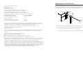
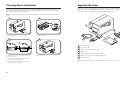
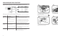
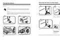
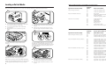
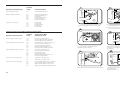
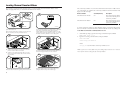
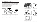
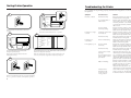
Getting Started Guide
P/N 064678-003
EasyCoder Printer
3400, 3440, and 3600
™
Norand Mobile System Division
Adjusting the Print Darkness
Intermec Τechnologies Corporation
6001 36th Avenue West
P.O. Box 4280
Everett, WA 98203-9280
Use the darkness adjust control to fine-tune the darkness of print on your labels. The fine
adjustments compensate for variations in the media, the printhead, or the printer. Set the
darkness adjust control after you enter the media sensitivity number.
U.S. technical and service support: 1-800-755-5505
U.S. media supplies ordering information: 1-800-227-9947
A
Canadian technical and service support: 1-800-688-7043
Canadian media supplies ordering information: 1-800-268-6936
B
1 2 3 4 5 6 7 8
Contact your local Intermec service supplier.
3400, 3440, and 3600 Bar Code Label
065145
Printer User’s Manual
Data Communications Reference Manual
044737
Model 200 Controller System Manual
063439
The information contained herein is proprietary and is provided solely for the purpose of allowing
customers to operate and/or service Intermec manufactured equipment and is not to be released,
reproduced, or used for any other purpose without written permission of Intermec.
I
O
1 2 3 4 5 6 7 8
Intermec Part Number
1 2 3 4 5 6 7 8
Related Manuals You Can Order
1 2 3 4 5 6 7 8
Outside U.S. and Canada:
3440G.055
Information and specifications in this manual are subject to change without notice.
A Locate the darkness adjust control on the back of the printer.
1998 by Intermec Technologies Corporation
All Rights Reserved
B Use a small straight-slot screwdriver to adjust the print darkness:
• To increase the print darkness, turn the control clockwise.
The word Intermec, the Intermec logo, JANUS, IRL, TRAKKER, EasyCoder, Duratherm, EZ Builder,
Precision Print, PrintSet, Virtual Wedge, and CrossBar are trademarks of Intermec Technologies
Corporation.
• To decrease the print darkness, turn the control counterclockwise.
Kimdura is a registered trademark of Kimberly Clark.
Kapton is a registered trademark of Dupont.
The name Centronics is wholly owned by GENICOM Corporation.
IBM is a registered trademark of International Business Machines Corporation.
Throughout this manual, trademarked names may be used. Rather than put a trademark ( ) symbol in
every occurrence of a trademarked name, we state that we are using the names only in an editorial
fashion, and to the benefit of the trademark owner, with no intention of infringement.
The software contained in the printer and the accompanying materials are copyrighted. Unauthorized
copying of the software, including software that has been modified, merged, or included with other
software, or the written materials is expressly forbidden without the prior written consent of Intermec.
All right, title, and interest in all copies of this software are and shall at all times remain the sole and
exclusive property of Intermec. Customer may be held legally responsible for any copyright
infringement that is caused or encouraged by its failure to abide by these terms.
25
Unpacking the Printer
Correcting Uneven Print Quality
You may experience problems in print quality (ribbon wrinkling or light print on one side of your
label) if the printhead is not making even contact with the label stock. You need a straight-slot
screwdriver to turn the bias adjust screw.
Remove the accessories, packing material, and the printer from the shipping container. Save the
shipping container and packing materials in case you need to move or ship your printer.
Verify the contents of the shipping container against the list below:
Note: To achieve the best print quality, adjust the bias adjust screw each time you use media of a different
width.
2
1
Po
we
r
Ale
rt
Em
pty
/P
au
se
Po
we
r
1
Al
er
t
Pow
er
Em
Ale
pt
y/
rt
Pa
Em
us
pty
e
/Pa
use
Fe
ed
/P
au
se
Fe
Fe
ed/
ed
Pa
/P
use
au
se
Inte
rmec
7
3440G.043
6
3440G.006
Remove the media cover.
Locate the bias screw.
4
78
46
06
P/N
In
te
k
te
sta
In
1
r
1.1
is
n
rin
g
ll
ol
ett
G
3
A
G
in
To
4
D
P
sio
ec
er
V
rm
3
2
5
e
uid
d
rte
Sta
0,
, 344
3400
oder r
EasyC00 Printe
6
and 3
B
3440G.001
Po
we
r
Al
er
t
Em
pt
y/
Pa
us
e
Fe
ed
/P
1
Intermec printer
2
AC power cord
3
PrintSet installation software disk
4
Ribbon core
5
Bar Code Label Printer Getting Started Guide
6
Media support (not shipped with 3600 printer)
7
Media envelope
au
A
R
OR
W
L
*E
AR
RO
WL
E*
se
3440G.032
3440G.022
To compensate for uneven print quality, turn the bias
adjust screw as shown.
A
If printing is light on right side of label, turn the
bias adjust screw counterclockwise.
B
If printing is light on the left side of label, turn
the bias adjust screw clockwise.
24
Replace the media cover.
Note: Make sure you remove all packing material from the printer before you proceed.
1
Understanding the Printer Front Panel
On the front panel of your printer, you will find one button and three light emitting diodes
(LEDs). Use the front panel LEDs to monitor the status of the printer:
LED
Power
Power
Green LED
Orange LED
State
Off
Flashing
On
Indication
Power off
Receiving data
Power on
Off
Flashing
On
Printing or idle
Over-temperature
System fault
Po
we
r
Ale
rt
Em
pty
/P
au
se
Fe
ed
/P
au
se
Inte
Alert
Yellow LED
6
5
A
Lit
rme
ton
Co
mp
Alert
Empty/Pause
c
an
y
34
00
Po
wer
/D
at
a
Ale
rt
Em
pt
y/
Pau
se
Fee
d/
Pau
se
Empty/Pause
Feed/Pause
Off
Flashing
On
Printing or idle
Paused
Media fault
Inte
rme
c
34
40
3440G.046
3440G.034
3440G.002
Note: The green LED on the 3440 printer front panel reads Power/Data.
The Feed/Pause button performs the following functions depending on the status of the printer:
Printer Mode
You Want To
What To Do
Idle
Feed out one label or a
minimum specified amount
of media.
Press and release the Feed/Pause button.
Use a lint-free cloth moistened with alcohol to remove
any dirt, adhesive, or debris from the print surface on
the bottom of the printhead.
Replace the media and ribbon.
Wait 5 to 10 seconds for the print surface to dry.
8
7
➤
Po
we
r
Al
er
t
Em
Continuously feed media.
Press and hold the Feed/Pause button. When
you release the button, the media stops feeding.
Take the printer offline.
Press the Feed/Pause button twice. Press the
button again to bring the printer online.
pt
y/
Pa
us
e
Fe
ed
/P
au
se
3440G.021
3440G.022
Printing
Powered on for
the first time
2
Pause the printer.
Press and release the Feed/Pause button. Press
and release the button again to resume printing.
Cancel the current print job.
Press and hold the Feed/Pause button until the
printer stops printing.
Print the hardware
configuration test label.
Press and hold the Feed/Pause button. See
“Testing Printer Operation” later in this
guide for more information.
Engage the printhead by rotating the head lift lever
counterclockwise until it locks in place.
Replace the media cover.
23
Connecting the Printer to a Power Supply
Cleaning the Printhead
1
2
1 2 3 4 5 6 7 8
In order for the printhead to provide good print quality, it must maintain close contact with the
media. Therefore, cleaning media debris from the printhead is very important. You should clean
the printhead after every roll, or 6,000 inches (152m), of media have been printed. Clean more often
if necessary.
1
2
3
Caution
Do not use sharp objects such as knives or screwdrivers to scrape the printhead
clean. Cleaning with sharp objects will damage the printhead. Clean with only a
cotton swab, a clean, lint-free cloth, or a tissue damp with isopropyl alcohol.
4
O
I
5
6
7
8
1 2 3 4 5 6 7 8
1
1 2 3 4 5 6 7 8
2
3
O
6
O
7
I
8
O
3440G.004
3440G.003
Turn the On/Off (|/O) switch on the back of the
printer to the off (O) position.
1 2 3 4 5 6 7 8
2
I
5
1
I
4
Conseil
N’utilisez pas d’objets pointus tels que couteaux ou tournevis pour nettoyer la tête
d’imprimante. Nettoyer avec des objets pointus endommagera la tête d’imprimante.
Nettoyez-la seulement avec de la ouate ou avec un linge propre et libre de peluches,
humecté avec de l’alcool d’isopropyl.
Make sure the DIP switches are set to their default settings.
Top Bank
1 2 3 4 5 6 7 8
Set switch 1 on (|). Set switches 2
through 8 off (O).
Bottom Bank Set switches 1 through 8 off.
Po
we
r
Al
er
t
Em
I
pt
y/
Pa
e
Fe
ed
/P
au
se
1 2 3 4 5 6 7 8
3
us
O
1 2 3 4 5 6 7 8
5
3440G.006
3440G.044
I
Turn the on/off switch to the off (O) position and
remove the power cord.
Remove the media cover.
4
4
3
I
O
O
3440G.005
3440G.007
Plug the AC power cord into the receptacle at the rear of the
printer.
Turn the On/Off switch to
the on (|) position.
wer
t
ty
/P
au
se
➤
Pa
use
rme
3440G.038
Rotate the head lift lever clockwise to release the printhead.
This raises the printhead so that you can clean it.
22
c
3440G.045
Remove the media and ribbon if necessary.
Plug the other end of the
power cord into a
grounded wall outlet or
surge protector.
When you power on the printer, the green LED on the front panel lights, the yellow and orange LEDs flash,
and the platen roller advances. The yellow LED then stays on until you load media.
3
Loading a Roll of Media
3400 and 3600 Printer Direct Thermal Media Sensitivity Settings
This procedure explains how to load a roll of direct thermal or thermal transfer media.
Approximate Sensitivity Rating
2
1
Sensitivity
Setting
Direct Thermal Media
700 Series High Sensitivity
740
720
Duratherm Lightning Plus 1
Duratherm Lightning Plus 2
400 Series Medium Sensitivity
460
450
440
420
European IR
Duratherm Lightning IR Labels 1
European Thermal
Duratherm Lightning Labels 1
100 Series Low Sensitivity
190
180
170
160
140
130
120
Duratherm Buff Tag
Duratherm II-1
European Tag
Duratherm II Tag
European Top
Duratherm II-2 Labels
European Thermal Economy Tag
C
Po
we
r
B
Al
er
t
Em
pt
y/P
au
se
Fe
ed
/P
au
se
➤
A
➤
3440G.006
3440G.009
A
B
C
Use your right hand to pull the bottom of the media
cover away from the base of the printer.
A
Use your left hand to lift the front of the media
cover upward.
Turn the supply roll retainer counterclockwise to
release it.
B
Slide it to the outer end of the supply roll post.
Turn the supply roll retainer clockwise to lock it.
Lift the media cover away from the top of the
printer.
3400 and 3600 Printer Thermal Transfer Media and Ribbon Sensitivity Settings
4
3
Sensitivity
Setting
Thermal Transfer Media and Ribbon
(Media/Ribbon Stock)
800 Series High Sensitivity (Paper)
864
854
834
European Uncoated/Standard 1
Duratran TTR Paper Labels/Standard 1
Duratran TTR Paper Tags/Standard 1
600 Series Medium Sensitivity (Plastic)
687
683
677
673
637
633
627
623
Duratran TTR Polyester 1/Premium 3/6/7
Duratran TTR Polyester 1/Premium
Duratran Syntran/Premium 3/6/7
Duratran Syntran/Premium
European Polyester/Premium
European Polyethelene/Premium
Duratran Kimdura/Premium 3/6/7
Duratran Kimdura/Premium
500 Series Medium Sensitivity (Paper)
567
563
557
553
537
533
527
523
517
513
Duratran II-1/Premium 3/6/7
Duratran II-1/Premium
Duratran II Tag-5 mil/Premium 3/6/7
Duratran II Tag-5 mil/Premium
European Tag/Premium 3/6/7
European Tag/Premium
Duratran II Tag-7 mil/Premium 3/6/7
Duratran II Tag-7 mil/Premium
European Coated/Premium 3/6/7
European Coated/Premium
300 Series Low Sensitivity (Plastic)
369
366
Super Prem. Poly./Super Prem.-3
Super Prem. Poly./Super Prem.-7
Approximate Sensitivity Rating
120066102605140
120066102605140
➤
3440G.014
3440G.008
Raise the printhead by rotating the head lift lever
clockwise.
5
➤
Save the small label attached to your roll of media or
the label with a 15 digit number stamped on it. You
will need it to set the correct media sensitivity number.
See ”Setting the Media Sensitivity Number“ later in
this guide for help.
6
➤
3440G.010
3440G.012
Place the roll of media on the supply roll post.
Note: If you are using a narrow roll of media (less than 3
inches), insert the media support between the roll of media
and the supply roll retainer before securing it in place.
4
A
Turn the supply roll retainer counterclockwise
and slide it up to the edge of the roll of media.
B
Turn the supply roll retainer clockwise to lock it
in place.
21
3440 Printer Direct Thermal Media Sensitivity Settings
Direct Thermal Media
700 Series High Sensitivity
720
Duratherm Lightning Plus 2
400 Series Medium Sensitivity
480
470
460
450
440
420
Duratherm Lightning IR Tag
Duratherm Lightning-2
European IR
Duratherm IR Lightning-1
European Thermal
Duratherm Lightning-1
100 Series Low Sensitivity
180
170
160
140
130
Duratherm II-1
European Tag
Duratherm II Tag
European Top
Duratherm II-2
8
7
➤
Approximate Sensitivity Ratings
Sensitivity
Setting
Unscrew the edge guide on the lower media guide.
9
Sensitivity
Setting
Thermal Transfer Media
(Media/Ribbon Stock)
800 Series High Sensitivity (Paper)
864
854
834
European Uncoated/Standard
Duratran TTR Paper Labels/Standard-1
Duratran TTR Paper Tags/Standard-1
600 Series Medium Sensitivity (Plastic)
687
677
633
627
623
Duratran TTR Poly. or Valeron/Prem.-3/6/7
Duratran Syntran/Premium-3/6/7
European Polyethelene/Premium
Duratran Kimdura/Premium-3/6/7
European Duratran Kimdura/Premium
567
565
563
533
527
513
Duratran II-1/Premium-3/6/7
European Duratran II/Premium
Duratran II/Economy
European Tag/Premium
Duratran II Tag-7 mil/Premium-3/6/7
European Coated/Premium
369
366
Super Prem. Poly./Super Prem.
Super Prem. Poly./Super Prem.-7
A
Slide the edge guide to the outer edge of the lower
media guide and screw it in place.
B
Pull down on the lower media guide to allow easy
access to the media path.
10
3440 Printer Thermal Transfer Media and Ribbon Sensitivity Settings
Approximate Sensitivity Ratings
3440G.013
3440G.011
3440G.015
Release the lower media guide. Unscrew the edge guide
and slide it in to the edge of the media. Screw the edge
guide in place.
Unroll several inches of media and route it
through the printer mechanism.
12
11
Pow
➤
500 Series Medium Sensitivity (Paper)
3440G.011
er
Ale
rt
Em
pty
/Pa
use
Fee
d/P
aus
e
Power
Alert
Empty/Pause
300 Series Low Sensitivity (Plastic)
3440G.022
Feed/Pause
200 Series Low Sensitivity (Kapton)
238
236
226
222
Gloss Polyimide (Kapton)/Gloss Super Prem.
Gloss Polyimide (Kapton)/Super Prem.-7
Matte Polyimide (Kapton)/Super Prem.-7
Matte Polyimide (Kapton)/Matte Super Prem.
EasyCoder
3440
3440G.021
Rotate the head lift lever counterclockwise until it locks.
3440G.020
Press the Feed/Pause button to advance one label
through the printer.
Replace the media cover.
20
5
Loading Thermal Transfer Ribbon
If you plan to print in thermal transfer mode, you must install a thermal transfer ribbon on the
ribbon supply hub after you install the thermal transfer media.
2
➤
1
The sensitivity number on each roll of thermal transfer media or ribbon has an asterisk (*) in place of
one of the digits. To optimize the sensitivity number for thermal transfer media, you combine the
digits as in this example.
Media or Ribbon
Sensitivity Rating
Description
Thermal transfer media
56*
The asterisk for the third digit is
reserved to identify the ribbon’s
sensitivity number.
Thermal transfer ribbon
5*7
The asterisk for the second digit is
reserved to identify the media’s
sensitivity number.
567
optimum sensitivity rating
SENSITIVITY NUMBER
5✩7
Po
we
r
Al
er
3440G.039
t
Em
pt
y/P
au
se
Fe
ed
/P
au
se
3440G.033
3440G.006
Open the media cover.
Make sure the printhead is raised. If not, turn the head
lift lever clockwise until the printhead releases.
3440G.033
Save the plastic bag that your media came in. Attached
to the bag is a label with a three-digit sensitivity
number printed on it. You need this number to set the
correct media sensitivity number. For help, see “Setting
the Media Sensitivity Number” later in this guide.
3
To set the sensitivity rating for direct thermal media, use the three-digit sensitivity rating located on
the roll of media or listed in the Direct Thermal Media Sensitivity Settings table, later in this guide.
To use DOS to set the media sensitivity number on a PC
1. At the DOS prompt, type the following command and press Enter:
MODE COM1 96,E,7,1,N
4
2. Type the following command lines and press Enter:
COPY CON COM1
<STX><SI>g1,567<ETX>^Z
Po
wer
Ale
rt
Em
pt
y/
where:
Pau
se
Pow
er
Fee
Ale
d/
rt
Pau
se
Em
pt
y/
Inte
Pau
se
rme
<SI>g1,567 sets the media sensitivity number to 567.
c
Fee
d/
Pau
se
3440G.030
3440G.016
A
B
Slide the empty ribbon core that comes with the
printer onto the ribbon rewind hub.
Slide the roll of thermal transfer ribbon onto the
ribbon supply hub with the ribbon roller unwinding clockwise.
5
Detach the leader from the thermal transfer ribbon roll
and unwind approximately 8 inches of ribbon.
Note: If you receive a write fault error, your cabling may be incorrect. See “Connecting the Printer to
Your System” earlier in this guide for more information.
6
➤
➤
➤
➤
➤
➤
3440G.018
3440G.017
Route the ribbon leader through the printer mechanism.
6
Attach the ribbon leader to the empty ribbon core
using the adhesive strip on the leader edge.
19
Setting the Media Sensitivity Number
8
7
➤
Media sensitivity is important because you use it to optimize print quality and print speed. The
three-digit sensitivity number specifies the amount of heat required by the printhead to image a
label. The amount of heat that each roll of media or ribbon requires is unique due to different
chemistries and manufacturing processes.
Intermec has developed heating schedules (the amount of heat required to image a label) to produce the highest possible print quality for Intermec media and ribbon combinations on Intermec
printers. Look for the three digit media sensitivity number on:
The side of the media roll. Use the last three digits (140 in the example) of the 15 digit number
stamped on the roll for the media sensitivity number.
•
A small label attached to the roll of media.
•
A small label attached to the plastic bag of your ribbon roll.
➤
•
3440G.040
Turn the ribbon rewind hub clockwise until the ribbon
runs smoothly through the printhead mechanism.
3440G.021
Lower the printhead by turning the head lift lever
counterclockwise until it locks.
120066102605140
SENSITIVITY NUMBER
5✩7
9
1
10
2
3
4
I
O
5
7
we
r
er
t
8
pt
y/
Pa
us
e
ed
/P
au
se
1
1 2 3 4 5 6 7 8
2
3440G.052
3
1 2 3 4 5 6 7 8
4
120066102605140
6
Po
Al
Em
Fe
I
5
O
6
7
8
3440G.022
3440G-019
Use this three-digit number to optimize print quality and print speed on your printer. You can
achieve the best print quality on the printer by using Intermec ribbon and media products.
The default printer setting for direct thermal media sensitivity is 420. For thermal transfer media,
the default setting is 567. Use the information on the packaging that you saved when loading
media and ribbon to determine the correct sensitivity number.
Use PrintSet, your third-party software, or the Intermec printer language (IPL) command set to
change the media sensitivity number. For help on how to set the media sensitivity number using
the printer command set, see the DOS example on the following page.
Enable thermal transfer printing by setting DIP switch 8
on the bottom bank of switches to the on (|) position.
Turn the printer power off and then on to activate the
new setting.
Close the media cover.
11
Alert
Empty/Pause
Feed/Pause
EasyCoder
3440
3440G.020
Press the Feed/Pause button to advance the ribbon
through the printer.
Note: When replacing the thermal transfer ribbon roll in the future, use the empty thermal transfer ribbon
core as the new rewinder core.
18
7
Testing Printer Operation
Troubleshooting the Printer
Print a hardware configuration test label to make sure your printer is operating correctly.
1
2
If your labels are not printing properly, check the following table to locate the symptom and correct
the problem.
I
O
Power
Symptom
Possible Causes
Solution
Blotches on labels.
Printhead is dirty.
Clean the printhead. For help, see “Cleaning the
Printhead” later in this guide.
Poor quality label or
ribbon stock.
Replace stock with Intermec label
and/or ribbon stock. See “Setting the Media
Sensitivity Number” later in this guide to set the
correct media sensitivity numbers for Intermec media and
ribbon stock.
Incorrect media
sensitivity setting.
Change sensitivity setting to match the type of
media you are using. For help, see “Setting the
Media Sensitivity Number” later in this guide.
Sensitivity command is
incorrectly set.
Change sensitivity setting to match the type of
media you are using. For help, see “Setting the
Media Sensitivity Number” later in this guide.
Printhead is dirty.
Clean the printhead. For help, see “Cleaning the
Printhead” later in this guide.
Printing is not
on the label.
Printer is misfeeding.
Make sure the media is installed properly along the
entire media path. For help, see “Loading a Roll of
Media” earlier in this guide.
Print quality is poor.
Incorrect media
sensitivity.
Change the sensitivity setting to match the type of
media you are using. For help, see “Setting the
Media Sensitivity Number” later in this guide.
Printhead is dirty.
Clean the printhead. For help, see “Cleaning the
Printhead” later in this guide
3440G.041
Alert
Empty/Pause
I
O
Feed/Pause
EasyCoder
3440
3440G.042
3440G.024
Turn the printer On/Off switch to the off (O)
position.
Press and hold the Feed/Pause button.
Turn the On/Off switch to the on (|) position.
3
4
Printing is too light
or dark.
3440 Hardware Configuration
Power
Alert
Empty/Pause
Feed/Pause
EasyCoder
3440
3440G.026
Memory Instal
Storage RAM
Image RAM
: 120 kilobytes
: 134 kilobytes
Mileage
Inches Processed
Inches Burned
Labels Cut
: 600
: 221
:0
Printhead
Width
Dot Size
Burn Pot Setting
: 1792 dots
: 2.5 mil
:0
Firmware Checksum
ROM0 (U9)
ROM1 (U8)
: 7BB9
: 2148
Program
Version
:
:
3440G.023
The Alert and Empty/Pause LEDs blink
during the printer self-test.
The printer feeds out one or two blank labels and then prints the
hardware configuration test label.
Uneven print contrast
(density).
Adjust the bias adjust screw. For help, see
“Correcting Uneven Print Quality” later in this guide.
Release the Feed/Pause button when the
media starts moving.
Note: The example label printed above is from the 3440 printer. The
values on your hardware configuration test label may be different.
You are using incorrect
label or ribbon stock to
print labels.
Use only Intermec label and ribbon stock to ensure
superior print quality and product performance. See
“Setting the Media Sensitivity Number” later on in this
guide to set the correct media sensitivity numbers for
Intermec media and ribbon stock.
Ribbon wrinkling.
Check to make sure that you installed the ribbon
correctly. For help, see “Loading Thermal Transfer
Ribbon”earlier in this guide.
5
I
I
O
O
3440G.042
Adjust the bias adjust screw. For help, see
“Correcting Uneven Print Quality” later in this guide.
3440G.041
Direct thermal/
thermal transfer
switch set in the
wrong position.
Set the DIP switch for the type of media you are
using. For help, see “Configuring the Serial Port
for Communications” earlier in this guide.
Turn the On/Off switch to the off (O) position and then to
the on (|) position to return to normal printer operation.
8
17
Communicating With the Printer
Connecting the Printer to Your System
You are now ready to print labels by downloading data from the host to your printer. Downloading
is the universal term used to describe the transfer of information from the host to any connected
peripheral device, such as your printer. When you transfer data from your printer to the host, you
are performing a process called uploading.
You can connect your printer to a PC, a local area network, an AS/400 (or other midrange
system), or a mainframe. Use this section to connect the printer to your system.
You can use several methods to download information in your data collection system. The next
sections describe different ways to communicate with the printer.
Using the PrintSet Software
Use PrintSet to quickly and easily configure the printer. You can upload the current configuration
settings, modify them, and then download them to your printer. Other features of PrintSet include
the ability to:
•
download graphics and fonts (including TrueType).
•
print test labels.
•
allocate memory.
•
download configuration files.
For help using PrintSet, refer to the online help portion of the application software.
Using Third-Party Software
Use the following table to determine the correct Intermec cable for your application. Cable
schematics for the PC serial cables appear on the next page.
For Connecting To
Use Intermec Cable
PC serial port
25F-25M, null modem, 9-wire
048668
9F-25M, null modem, 7-wire
PC parallel port
Parallel port cable
048693
051211
2
1
1 2 3 4 5 6 7 8
Use your third-party software to create label formats and convert graphics into a user-defined
character (UDC) format that your printer can interpret. Refer to your third-party documentation,
for more information.
You can connect your printer to either a serial port or a parallel port (if you have the parallel option
installed) on your PC. You must provide the correct cables to connect the printer. Contact your
Intermec representative for ordering assistance if you do not have the appropriate cables.
1 2 3 4 5 6 7 8
You can use third-party software to set many of the printer parameters. You can configure the
parameters that your software does not set by using the IPL command set or the printer’s
DIP switches.
Connecting the Printer to a PC
I
I
O
O
Using the Intermec Printer Language (IPL) Command Set
You can also create labels by downloading formats (designs) and data you create with the printer
command set. For help, see the IPL Programming Reference Manual available on the Internet at
www.intermec.com. You can use the printer command set to perform any function or activate any
feature of your printer except for those features or functions that are set with the DIP switches.
3440G.042
3440G.025
Turn the On/Off switch to the off (O) position.
Plug the 25-pin connector into the serial (A) or parallel
(B) communications port on the rear of the printer.
Plug the other end of the cable into a serial (COM port)
or parallel port on your PC.
Note: If you are connecting the printer to a serial port on your PC, you may need to change the serial port
configuration of your PC to match the printer. See “Configuring the Serial Port for Communications” later in
this guide for the default printer configuration settings.
16
9
RS-232 Null Modem Cable for 25-pin PC (Intermec Part Number 048668)
DIP Switch Settings
Bottom Bank Switch Number
Top Bank Switch Number
SHIELD
25-PIN (SOCKET) D-SUB
METAL BACKSHELL
25-PIN (PLUG) D-SUB
METAL BACKSHELL
CHASSIS GROUND
1
1
CHASSIS GROUND
TRANSMITTED DATA
2
3
RECEIVED DATA
2
TRANSMITTED DATA
CARRIER DETECT
RECEIVED DATA
3
REQUEST TO SEND
4
CLEAR TO SEND
5
8
DATA SET READY
6
20 DATA TERMINAL READY
GROUND
7
7
GROUND
DATA TERMINAL READY 20
6
DATA SET READY
CARRIER DETECT
8
4
5
CLEAR TO SEND
PRINTER
PC
10
Parity Selection
Even*
Odd
None
None
OFF
1
2
3
O
1
O
1
O
1
O
1
O
O
1
1
O
O
1
1
O
O
O
O
1
1
1
1
4
5
6
7
8
O O
1 O
O 1
1 1
Number of Data Bits
7 Bit*
8 Bit
O
1
O O
*
O = OFF
1 = ON
ON
Multi-drop Address Selection
*A
B
C
D
E
F
G
H
I
J
K
L
M
N
O
P
Q
R
S
T
U
V
W
X
Y
Z
0
1
2
3
4
5
Protocol Selection
XON/XOFF*
Intermec Protocols
SHIELD
25-PIN (PLUG) D-SUB
METAL BACKSHELL
1
CHASSIS GROUND
RECEIVED DATA
2
2
TRANSMITTED DATA
TRANSMITTED DATA
3
3
RECEIVED DATA
8
CARRIER DETECT
DATA SET READY
CLEAR TO SEND
8
REQUEST TO SEND
7
DATA TERMINAL READY
4
6
DATA SET READY
6
20 DATA TERMINAL READY
CARRIER DETECT
1
5
CLEAR TO SEND
4
REQUEST TO SEND
5
7
GROUND
AT
PRINTER
NOTE: The metal backshell is connected directly
to the shield to achieve electrostatic discharge
(ESD) immunity.
Baud Rate Selection
19,200
9,600*
4,800
2,400
1,200
38,400
57,600
reserved
Default settings are noted with an
3440G.053
RS-232 Null Modem Cable for 9-pin PC (Intermec Part Number 048693)
GROUND
ON
Reserved
NOTE: The metal backshell is connected directly
to the shield to achieve electrostatic discharge
(ESD) immunity.
9-PIN (SOCKET) D-SUB
METAL BACKSHELL
OFF
O = OFF
1 = ON
2
3
4
5
O
1
O
1
O
1
O
1
O
1
O
1
O
1
O
1
O
1
O
1
O
1
O
1
O
1
O
1
O
1
O
1
O
O
1
1
O
O
1
1
O
O
1
1
O
O
1
1
O
O
1
1
O
O
1
1
O
O
1
1
O
O
1
1
O
O
O
O
1
1
1
1
O
O
O
O
1
1
1
1
O
O
O
O
1
1
1
1
O
O
O
O
1
1
1
1
O
O
O
O
O
O
O
O
1
1
1
1
1
1
1
1
O
O
O
O
O
O
O
O
1
1
1
1
1
1
1
1
O
O
O
O
O
O
O
O
O
O
O
O
O
O
O
O
1
1
1
1
1
1
1
1
1
1
1
1
1
1
1
1
6
7
8
O
1
XON/XOFF Selection
No Status Response*
With Status Response
O
1
DT/TTR
Direct Thermal*
Thermal Transfer
Default settings are noted with an
1
O
1
*
3440G.027
3440G.054
15
Configuring the Serial Port for Communications␣
Connecting the Printer to a Network
The serial port settings of your printer should match those of your PC or network controlling
device. The default settings of the printer are:
You can connect your printer to Novell NetWare networks, Token Ring networks, or TCP/IP networks. You can also connect the printer to an AS/400 (or other midrange system) or an IBM mainframe.
Setting
For Connecting To
You Need
Intermec Part Number
Baud rate
9600
Network
Network interface adapter
Contact Intermec or purchase separately
Parity
Even
Word length selection
7-bit word
Twinax adapter card
056835
Protocol
XON/XOFF no status response
Twinaxial cable
Device address
A
(Purchase cable equivalent to IBM
part number 7362267 or 7362062)
Media type
Direct thermal
Coax adapter card
056836
Coaxial cable
(Purchase cable equivalent to IBM
Parameter
AS/400
Mainframe
part number 2577672 or 1833108)
Determine which parameters you need to change and which DIP switches you need to set. Use the
DIP switch table on the following page.
The network interface adapter (for example, Ethernet) connects to the parallel port of the printer.
Your network must be able to use XON/XOFF (hardware handshake) protocol. If you are installing
your printer in a network environment, you may need to change the serial port settings on the
printer to match the requirements of your network. You can determine the communications
requirements for your network by referring to the controlling device documentation.
The following table provides the maximum baud rates for the printers.
Printer
Maximum Baud Rate
3400B
19,200
3400C
38,400
3440
57,600
3600
19,200
If the controlling device is an Intermec product, refer to the following manuals for instructions and
information on the necessary cabling and connections.
• Model 200 Controller System Manual (Intermec Part No. 063439)
• 9154 Multi-Drop Line Controller System Manual (Intermec Part No. 048517)
• 9161B Installation Manual (Intermec Part No. 049572)
1
• 9180 Network Controller User’s Manual (Intermec Part No. 054292)
2
1
• RF System User’s Manual (Intermec Part No. 053574)
2
• Data Communications Reference Manual (Intermec Part No. 044737)
3
4
I
O
5
6
If you need to change the printer’s communications parameters, follow the procedures in
“Configuring the Serial Port for Communications” later in this guide.
7
I
8
I
1
2
O
3
O
4
5
I
O
6
3440G.041
7
3440G.042
8
3440G-035
Use a small straight-slot screwdriver to set the appropriate
DIP switches on or off.
Turn the printer power off and then on again.
For example, if you want to change the media type to
thermal transfer, set DIP switch 8 on the bottom bank of
switches to the on (|) position.
14
11
Verifying Printer Communications With Your System
Once you have the printer connected to your system, you need to verify that the printer
communicates with your system. The easiest way to test communications is to set the printer to Data
Line Print mode and send down a character string from your system.
To use DOS to verify printer communications
1. At the DOS prompt, type the following command and press Enter to configure the serial port:
MODE COM1 96,E,7,1,N
If you have just printed a hardware configuration test label, start with Step 4.
2. Type the following command lines and press Enter:
COPY CON COM1
2
1
ABCDEF^Z
I
Power
O
where:
Alert
I
3440G.041
Empty/Pause
O
COPY CON COM1 tells the PC to copy the next line of information to communications port
COM1.
ABCDEF are random characters typed at the host.
Feed/Pause
^Z (Ctrl-Z) Enter sends the information to the printer.
3440G.042
EasyCoder
3440
The printer prints the characters (see step 4 on previous page for example).
3440G.020
Turn the On/Off switch to the off (O) position.
Press and hold the Feed/Pause button. Turn the
On/Off switch to the on (|) position.
3
4
Power
Note: If you are using a different platform to communicate with your printer, please refer to your system
user’s manual and the IPL Programming Reference Manual for information on downloading commands.
Note: If you receive a write fault error, your cabling may be incorrect. See “Connecting the Printer to
Your System” earlier in this guide for more information.
Alert
Empty/Pause
Feed/Pause
EasyCoder
3440
3440G.029
3440G.026
Release the Feed/Pause button after the hardware
configuration test label prints.
5
I
Send down some characters from your system.
At this point the printer does not attempt to interpret
any printer commands. It simply prints each character
with its hexadecimal equivalent underneath.
I
O
O
3440G.041
3440G.042
Turn the printer power off and then on again.
Note: An example using DOS to verify printer communications follows this procedure. If this procedure does
not work, check to make sure that the DIP switches are set to the default configuration and that the printer
cable is securely plugged into the correct port of your system.
12
13