1
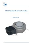
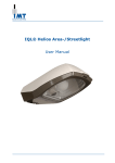
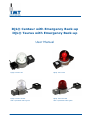
IQL® Centaur with Emergency Back-up
IQL® Taurus with Emergency Back-up
User Manual
IQL® Centaur EM
IQL® Taurus EM
IQL® Centaur EM-RB
With replacable batterypack
IQL® Tauris EM-RB
With replacable batterypack
User Manual
IQL® with Emergency Back-up
Contents
1.
2.
2.1
2.2
2.3
3.
4.
5.
5.1
5.2
6.
6.1
6.2
6.3
6.4
6.5
7.
7.1
7.2
7.3
7.4
7.5
7.6
7.7
7.8
7.9
8.
9.
10.
11.
Safety..................................................................................................................................... 3
Warranty ................................................................................................................................ 3
General.................................................................................................................................... 3
Life span .................................................................................................................................. 3
Shelf life .................................................................................................................................. 4
Type plate .............................................................................................................................. 5
Product Description................................................................................................................ 7
Specifications ......................................................................................................................... 8
General.................................................................................................................................... 8
Dimensions .............................................................................................................................. 8
Installation ............................................................................................................................ 9
Preparation .............................................................................................................................. 9
Assmbly ................................................................................................................................... 9
For IQL-EM-RB: Mounting the Battery Pack .................................................................................10
Connections ............................................................................................................................11
Tips for specific applications ......................................................................................................11
Use ....................................................................................................................................... 13
Commissioning ........................................................................................................................13
Switching on the emergency lighting ..........................................................................................13
‘Unmanned’ function .................................................................................................................13
Functionality of the status LEDs .................................................................................................13
Error contact ...........................................................................................................................13
Error reset ..............................................................................................................................13
Self-test..................................................................................................................................13
Insulation test .........................................................................................................................14
For IQL-EM-RB Changing the Battery Pack ..................................................................................14
Maintenance......................................................................................................................... 14
Recycling.............................................................................................................................. 14
Contact details ..................................................................................................................... 14
EC Declaration of Conformity ............................................................................................... 15
Copyright © IMT B.V.
All rights reserved.
No part of this User Manual may be copied, redistributed, published or changed without the prior written
permission of IMT B.V.
User Manual
IQL® with Emergency Back-up
2
Version 6.4 201303
User Manual
IQL® with Emergency Back-up
1. Safety
In order to use the product safely and optimise the life of the product, the following instructions must be
observed.
Only qualified personnel may install the product.
Work in accordance with locally applicable safety standards and regulations.
Ensure that there is no mechanical load applied to the light fitting during installation.
If excessive tension is applied to the mounting feet during installation, such as when mounting on an
uneven surface, the spot welds on the mounting feet can be torn free from the light fitting.
Use all the mounting holes when installing the light fitting.
Ensure that the cable gland is suitable for the dimensions of the type of cable that will be connected.
This is necessary to ensure the IP protection.
Ensure that the cable gland used has an IP level of IP66, IP67 or IP68 in conformance with EN 60529,
and in case of an explosion proof lighting fixture, is Ex-e certified according to IEC 60079-7.
When using metal glands, use an earthing plate and locknut on the inside of the junction box.
Ensure there is a reliable connection to the earthing system, both with the external earthing point and
with the connection in the light fitting junction box.
Never open the light fitting housing.
Never open the battery pack.
Do not clean the light fitting with a high pressure steam or water jet. This will avoid damage that falls
outside the guarantee terms.
For IQL-EM-RB
When replacing the battery pack, always make sure the Main Power is switched off, and the
emergency lights are out.
2. Warranty
2.1 General
The guarantee on the IQL-EM and IQL-EM-RB series of light fittings is only applicable when the light fitting is
used within the operational limits. And counts for the fitting only, not for the batteries, for the batteries a 1
year warranty is applicable.
Operational limits are:
The minimum and maximum ambient temperature for the IQL-EM and IQL-EM-RB is -20°C to +40°C.
The light fitting must be installed by a qualified person and in compliance with the installation
instructions.
Damage caused by incorrect installation, accidents or external influences such as lighting strike and
harmonic distortion not in accordance with EN 50055, are not covered by the guarantee.
The lighting level of the light fitting depends on the temperature and is therefore not covered by the
guarantee.
If an IQL-EM or IQL-EM-RB light fitting fails within the warranty period (with the exception of the batteries),
IMT B.V. will supply a new light fitting with a comparable specification free of charge. Before the guarantee can
be confirmed, a defective light fitting must be sent to IMT B.V. at the user’s expense for inspection. After this
inspection the user will be informed of the result(s). See invoice for individual guarantee agreements.
2.2 Life span
The life expectancy of batteries depends greatly on the average ambient temperature. Frequent charge and
discharge cycles contribute to a longer life span.
When the QL lamp burns continuously (for the IQL-EM only), this will ad 10 °C to the ambient temperature,
which will influence life expectancy, see below.
Ambient temperature
TA ≤ 20 °C
TA = 30 °C
TA = 40 °C
Life expectancy
->
± 10
years
->
± 6
years
->
± 2,5 years
With QL lamp burning continuously (for IQL-EM)
± 6
years
± 2,5 years
± 1
years
Switching the light fitting with a semiconductor photoelectric cell or a semiconductor relay has no known effect
on the life span of the light fitting.
It is expected that more than 70% of the original illumination power will be retained after 80,000 operating
hours.
User Manual
IQL® with Emergency Back-up
3
Version 6.4 201303
User Manual
IQL® with Emergency Back-up
2.3 Shelf life
The shelf life of batteries is limited. At higher temperatures the batteries will self discharge quicker. The
fixtures are delivered with fully charged batteries. To avoid permanent damage to the batteries by over
discharging, it is important to set the fixtures in service before the shelf life has expired. The shelf life is
largely determined by the ambient temperature, see values shown in the following table.
Ambient temperature
TA ≤ 20 °C
TA = 30 °C
TA = 40 °C
Shelf
->
->
->
life
± 9 months
± 4 months
± 6 weeks
Also for fixtures already set in operation it is important that, after a discharging cycle, the fixtures are being
powered before the above mentioned time-limits have elapsed, to prevent permanent damage to the batteries.
User Manual
IQL® with Emergency Back-up
4
Version 6.4 201303
User Manual
IQL® with Emergency Back-up
3. Type plate
The type plate for the light fitting:
It contains the following information:
1.
Type
: Normal
: Normal with RB
IQL55-EM
IQL55-EM-RB
2.
Ambient temp.
: Normal temperature range
-20°C to +40°C
3.
Serial number
4.
Year of manufacture
5.
Frequency
: AC 50/60
6.
Voltage
: 230Vac ±10%
7.
Current
: 230Vac
230Vac
8.
Marking
: II 2 GD Ex e mb II T4 T135°C IP66 (For IQL-EM)
: II 2 GD Ex d e mb IIC T4 T135°C IP66 (For IQL-EM-RB)
9.
Mechanical protection: IP 66
55W
85W
260mA
400mA
10. Revision
: electronics version 1.1 0r 2.0
11. Unmanned
: 24 Vdc for unmanned situations
User Manual
IQL® with Emergency Back-up
IQL85-EM
IQL85-EM-RB
5
Version 6.4 201303
User Manual
IQL® with Emergency Back-up
For IQL-EM-RB
The replaceable battery pack has the following type plate:
It contains the following information:
1. Type
: Repl. Batt. Pack IQL-EM-RB or Repl. Batt.
2. Ambient temp.
: Normal temperature range
-20°C to +40°C
3. Serial number
4. Year of manufacture
: 2011 –xx
5. Voltage
: Unom = 16Vdc
6. Current
: Inom = 1.2 A
xx = weeknr loading
7. Mechanical protection : IP66
8. Marking
: II 2 GD Ex d e mb IIC T4 T135°C IP66
User Manual
IQL® with Emergency Back-up
6
Version 6.4 201303
User Manual
IQL® with Emergency Back-up
4. Product Description
The IQL-EM and IQL-EM-RB light fittings have been designed for use in demanding conditions.
The characteristics of the IQL-EM and IQL-EM-RB light fittings are:
Approx 100,000 hours maintenance-free operation (for the lamps )1
sealed for life
vibration proof
based on the principle of induction
use of long-life high-power LEDs
explosion-safe model ATEX category 22 suitable for use in Zone 1 & 21
back-up function: LEDs will go on during mains power failure
For IQL-EM-RB light fittings are suitable for use in the following:
replaceable battery pack, by explosion proof connectors.
The IQL-EM and IQL-EM-RB light fittings are suitable for use in the following:
(petro)chemical industry
offshore industry
power stations
general industry
docks
1
See invoice for individual guarantee agreements.
2 Risk of the presence of an explosive gas mixture or an explosive dust atmosphere during normal operations is high (10 tot
1.000 hours per year).
User Manual
IQL® with Emergency Back-up
7
Version 6.4 201303
User Manual
IQL® with Emergency Back-up
5. Specifications
5.1 General
Housing
Lens
Colour recognition
Mechanical protection
Voltage
Power
Burning position
(Re)ignition
Cos. Phi
Connection
Emergency Lighting
Back-up function
Batteries
For IQL-EM-RB
Replaceable Battery Pack
Connection with battery pack
:
:
:
:
:
:
:
:
:
:
:
:
Corrosion-proof steel 316L (AISI)
Borosilicate glass
Centaur Ra>80, Taurus NA
IP66
230Vac, ± 10%
55 or 85 watt
Universal
Immediate
>0,92
fitted as standard with a junction box, type E012129, connection
6 power LEDs (18watt)
The autonomy of the system depends on the T ambient, as follows:
°C
-20
-10
0
+10
+20
+30
+40
Hrs
1.45
2.20
2.45
3.00
3.20
3.30
3.45
Automatic charging- and discharging cycle
Charging within 12 hours
LED status indication
Automatic test function
: Standard placed in a junction box, type E016169
: Standard placed in a junction box, type E016169
Mounted on a stainless steel plate 316L
Receptacle (female) with M20 thread, plastic (316L for LT version)
: Connection cable of 250 mm with plug (male) on fixture, plastic
(316L for LT version)
5.2 Dimensions
IQL-EM
IQL-EM-RB
User Manual
IQL® with Emergency Back-up
8
Version 6.4 201303
User Manual
IQL® with Emergency Back-up
6. Installation
6.1 Preparation
1. Check that the light fitting will be installed in an environment that matches the ambient temperatures, gas
group
and temperature class. This data is included on the light fitting type plate.
WARNING
The installation and setting to use of the light fitting needs to take place before expiry of the
shelf life. See 2.3.
WARNING
The installation of the light fitting in an environment that does not match the specified
conditions can result in a dangerous situation.
WARNING
The installation of the light fitting in an environment that does not match the specified
ambient temperatures can have a strong negative effect on the life span of the light fitting.
2. Choose the correct type of protection for the light fitting. The protection device needs to be a fuse
or a circuit breaker with at least 4 kA with a C characteristic.
3. Determine the number of light fittings that can be installed in each group. Consult the following table for
this.
Installation protection
B Type, 10 A
C type, 10 A
B Type, 10 A
C type, 16 A
55 W
20
20
30
35
85 W
20
20
30
35
Inrush currents
55 W
85 W
Inrush currents
12 A
12 A
Peak duration
170 μs
170 μs
When using 30 mA earth leakage switches, provision must be made for a maximum of 30 light fittings on one
switch.
6.2 Assmbly
1.
2.
Take the light fitting out of the packaging.
Inspect the light fitting for mechanical damage.
WARNING
The installation of the light fitting in an environment that does not match the specified
conditions can result in a dangerous situation.
WARNING
The installation of the light fitting in an environment that does not match the specified
ambient temperatures can have a strong negative effect on the life span of the light fitting.
3.
Mount the light fitting.
Ensure there is a reliable connection to the earthing system, both with the external earthing point and
with the connection in the light fitting junction box.
Ensure that the cable gland is suitable for the dimensions of the type of cable that will be connected,
and in case of an explosion proof lighting fixture, is Ex-e certified according to IEC 60079-7. This is
necessary to ensure the IP protection, and to be suitable for an hazardous environment.
WARNING
Ensure that there is no mechanical load applied to the light fitting during installation.
If excessive tension is applied to the mounting feet during installation, such as when
mounting on an uneven surface, the spot welds on the mounting feet can be torn free from
the light fitting.
4.
5.
6.
7.
8.
Route the connecting cable correctly through the cable gland. Make especially certain that the cable gland
is suitable for the dimensions of the type of cable that will be connected. This is necessary to ensure the
IP protection.
Cut the cable to length.
Connect the cable to the terminals. The standard terminals in the junction box are suitable for a core
diameter of 0-4 mm².
Connect the wiring in accordance with one of the situations (see 6.4 Tips for specific situations).
Check the connections that have been made.
User Manual
IQL® with Emergency Back-up
9
Version 6.4 201303
User Manual
IQL® with Emergency Back-up
9.
Close the junction box.
WARNING
The installation must be carried out in accordance with (NEN-EN) IEC 60079-14.
6.3 For IQL-EM-RB: Mounting the Battery Pack
WARNING
The Main Power must be shut off when battery pack is being connected.
1.
2.
Mount the battery pack to the construction within 25 to 35 cm of the lighting fixture.
Make sure the MAIN POWER is switched off.
WARNING
Never open the battery pack. Sealed for life.
Making the connection.
3.
4.
Remove the protective caps of both parts.
Insert the plug (male) from the fixture in the coupler (female) of the battery pack until the 1e stop. Make
sure the connectors are in the correct position. See Fig A and B.
5.
Then turn the plug through ca. 30° to the right until reaching the stop and then insert fully (C + D)
6.
Finally, screw down the coupling ring tightly to establish the IP protection and the mechanical connection.
See E and F.
7.
8.
Then connect the protective caps together.
Switch on Main Power.
Disconnecting.
Proceed the above in the reverse order to disconnect the plug and the coupler system.
Make sure Main Power is switched off, and wait for the emergency lights to go out.
After disconnecting, replace the protective caps. The connectors are generally to be kept sealed.
User Manual
IQL® with Emergency Back-up
10
Version 6.4 201303
User Manual
IQL® with Emergency Back-up
6.4 Connections
In the light fitting junction box there is a terminal block as shown in the illustration
The following connections can be made:
L-N
: Permanent connections for a 230 Vac power supply. This power supply is used to supply the batteries
so that they remain fully charged.
LS-NS : Connections for a switched 230 Vac power supply. The main lamp is switched on and off with this
supply
This power supply is not connected to the battery charging circuit. If only this power supply is
connected, the batteries will not be charged and the emergency lighting will be inoperable. The
batteries will discharge within a few months, and get permanently damaged, see 2.3.
+/E1-E2
: Connection for the so-called ‘unmanned’ function. When 24 Vdc (maximum 10 mA) is connected to
these terminals, the emergency lighting will not be switched on when the 230 Vac voltage is
interrupted.
: Error output for the emergency electronics. In an error situation, a contact will be switched. This is a
voltage-free NO contact, suitable for a maximum voltage of 230 Vac and a current flow of 5 A.
6.5 Tips for specific applications
The system is permanently connected to the power supply.
ERROR CONTACT (NO)
24 Vdc ‘UNMANNED’ CONNECTION
230 Vac POWER SUPPLY
During the installation it may be undesirable to allow the emergency lighting to switch on every time the
permanent supply is switched off (for example during testing). To prevent this, the jumpers can be removed
temporarily from the terminal block. Ensure that the jumpers are re-fitted after completing the installation.
User Manual
IQL® with Emergency Back-up
11
Version 6.4 201303
User Manual
IQL® with Emergency Back-up
The batteries and main lamp are each connected to a separate group.
Permanent supply
Switched supply
If the batteries and the main lamp are both supplied from a separate group, the permanent supply will charge
the batteries. The switched supply is used to switch the main lamp on and off. This assumes that both power
supplies are interrupted in an emergency. In this case the emergency lighting will be switched on.
WARNING
Remove the jumpers fitted as standard between L-LS and N-NS.
Common neutral
Switched phase
Permanent phase
Earth
The batteries and main lamp are connected to the same group.
If the batteries and the main lamp are both supplied from the same group, the permanent supply will charge
the batteries. The switched supply is used to switch the main lamp on and off. This assumes that both power
supplies are interrupted in an emergency. In this case the emergency lighting will be switched on.
WARNING
Remove the jumpers fitted as standard between L-LS.
User Manual
IQL® with Emergency Back-up
12
Version 6.4 201303
User Manual
IQL® with Emergency Back-up
7. Use
7.1 Commissioning
The main lamp in the light fitting can be used as soon as the installation is completed. After installation, the
light fitting must be connected to a permanent power supply for at least 12 hours. After this the batteries will
be fully charged.
7.2 Switching on the emergency lighting
The emergency lighting is only switched on in an emergency lighting condition. This condition means that there
is no 230 Vac power supply and there is no 24 Vdc power supply to the + and – terminals (unmanned
switching).
WARNING
The emergency lighting feature is only available when the battery pack is connected.
WARNING
When the emergency lights have been switched on, it is important to reapply the 230Vac
main power, before the in 2.3 mentioned time limits have elapsed, to prevent permanent
damage caused by self discharging.
7.3 ‘Unmanned’ function
In the offshore industry there are situations when a platform is partially or completely unmanned.
When leaving a platform, a 24 Vdc voltage can be switched on. This 24 Vdc voltage tells the light fitting that
there is no-one on board. This means that no emergency lighting operation is required if the 230 Vac generator
voltage is interrupted.
As soon as the 24 Vdc to the light fitting is switched off, it switches to stand-by mode immediately and will
switch on the emergency lighting if the main power supply is interrupted.
7.4 Functionality of the status LEDs
The emergency light fitting has various status LEDs. These LEDs are located on the ‘ring’ where the main LEDs
are mounted. The LEDs have the following function:
Yellow
The light fitting is carrying out the self-test.
LED
Green LED This LED indicates the battery charge status.
- Flashing:
The batteries are charging.
- Continuously lit:
The batteries are (almost) fully charged.
- Off:
The light fitting is switched in an unmanned situation or there is no voltage on
terminals L and N in the junction box.
Red LED
This LED indicates an error code. In the event of a failure, the red LED flashes a number of times during a
40 second cycle. The error code is indicated by the number of flashes. These error codes are:
1 flash: System has reached end of design life span (>87,600 hours).
2 flashes: Charging current is too high.
3 flashes: Battery voltage is too high.
4 flashes: Battery voltage is too low while the permanent power supply is present.
5 flashes: Internal circuit voltage is too high.
7.5 Error contact
In the event of an error situation, the Normally Open (NO) contacts between the E1 and E2 terminals will close
(changes to a Normally Closed, NC).
WARNING
Contact your supplier if there is a malfunction. If possible, state the error code indicated by
the red LED.
See the section ‘Functionality of the control LEDs’ for an overview of the possible error codes.
7.6 Error reset
As soon as an error situation has been resolved (either automatically or by manual intervention), the light
fitting must be reset. A reset means that both 230 Vac supplies must be disconnected from the light fitting.
During this reset the indicator LED with an error message is reset and the error contact is switched back to
being a Normally Open (NO) contact.
7.7 Self-test
After the light fitting has been switched on for approximately 50 days (both 230 Vac circuits are connected to a
supply), an automatic self-test is carried out. During this test a number of parameters are checked, such as the
status of the batteries and the operation of the LEDs.
User Manual
IQL® with Emergency Back-up
13
Version 6.4 201303
User Manual
IQL® with Emergency Back-up
During the test the yellow indicator LED is on. If the Unmanned function is switched on during the test, the test
will be interrupted.
This test takes place roughly every 50 days. This means that if there are multiple emergency light fittings
installed in one location, they are not all discharged at the same time so that the emergency lighting operation
is guaranteed.
7.8 Insulation test
Installations in which IQL-EM light fittings are installed can be checked with an insulation test. For this test,
apply a maximum of 500 Vdc between earth and a phase or neutral connection.
WARNING
Never apply more than 500 Vdc between a phase and the neutral connection.
During production, all light fittings have been subjected to a dielectric test (1500 Vac for 60 seconds for 230
Vac circuits and 500 Vac for 60 seconds for 24 Vdc circuits). In addition, the light fittings have also been
subjected to an endurance test.
7.9 For IQL-EM-RB Changing the Battery Pack
Installations in which IQL-EM light fittings are installed can be checked with an insulation test. For this test,
apply a maximum of 500 Vdc between earth and a phase or neutral connection.
WARNING
Main Power needs to be shut off, when battery pack is being replaced.
WARNING
The white emergency lights should not be burning when battery pack is being replaced..
When a battery pack is being replaced, it is important that Main Power is switched off, and the emergency
lights have stopped burning.
Disconnect the connector according to the instructions in paragraph 6.3
Dismount the battery pack.
Mount the new battery pack.
Connect the connectors according to the instructions in paragraph 6.3
Switch on Main Power only after making sure all is connected well.
8. Maintenance
The light fitting and battery housing are ‘sealed for life’ and cannot be opened. Consequently maintenance as
laid down in the IEC 60079-17 standard is not applicable; a visual inspection for correct operation will suffice.
WARNING
Opening the light fitting and/or the battery housing completely voids the warranty.
9. Recycling
For recycling the light fitting, agreements have been made with local bodies within the context of the WEEE
directive.
Contact your local partner (see the chapter ‘Contact details’). The local partner will be responsible for further
processing.
10.
Contact details
IMT B.V.
Pascalweg 10a, 4104 BG Culemborg
P.O. Box 88, 4100 AB Culemborg
THE NETHERLANDS
Phone : +31 (0)88 – 12 69 100
Fax
: +31 (0)88 – 12 69 101
E-mail : [email protected]
For an up-to-date overview of all national and international contacts, visit our website: www.imt.eu.
User Manual
IQL® with Emergency Back-up
14
Version 6.4 201303
User Manual
IQL® with Emergency Back-up
11.
EC Declaration of Conformity
The undersigned, representing the company
IMT B.V.
Pascalweg 10a
4104 BG Culemborg
The Netherlands
Phone :+31 (0) 88 - 12 69 100
herewith declares that the product, emergency light fitting type IQL-EM, IQL-EM-LT, IQL-EM-RB or IQLEM-RB-LT, marked with Ex II 2 GD Ex e mb II T4 T135˚C, IP66 or Ex II 2 GD Ex d e mb II T4 T135˚C, IP66
for RB versions, complies with the terms of the EC directive(s), including all applicable supplements.
94/9/EC
Equipment and protective systems intended for use in potentially explosive atmospheres
2004/108/EC
Electromagnetic Compatibility
And with the provisions of the following standards and/or technical specifications
Standard
Issue
Title
NEN 60079-0
2004
Electrical apparatus for potentially explosive atmospheres.
General requirements.
NEN 60079-7
2003
Electrical apparatus for potentially explosive atmospheres.
Increased safety “e”.
NEN 60079-18
2004
Electrical apparatus for potentially explosive atmospheres.
Encapsulation “m”.
NEN 60079-1
2004
Electrical apparatus for potentially explosive atmospheres.
Flameproof enclosures “d”.
NEN 50281-1-1
1998
Electrical apparatus for use in the presence of combustible dust part
1-1: electrical apparatus protected by enclosures – construction and
testing.
EN 61547
1995
EN 61000-3-2
2000
Equipment for general lighting purposes. EMC immunity requirements.
Limits for harmonic current emissions (equipment input current up to
and including 16A per phase).
EC type certificate number KEMA 06 ATEX0261 issued by:
Dekra Certification B.V.
Utrechtseweg 310
6812 AR ARNHEM
The Netherlands
Identification number: 0344
Culemborg, 20 juni 2011
IMT B.V.
R.L.L.M.G. Mignot, Managing director
User Manual
IQL® with Emergency Back-up
15
Version 6.4 201303
IMT B.V.
Pascalweg 10a, 4104 BG Culemborg
P.O. Box 88, 4100 AB Culemborg
Tel: +31 (0)88 – 12 69 100, Fax +31 (0) 88 – 12 69 101
www.imt.eu, [email protected]