1
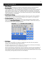
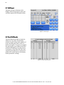
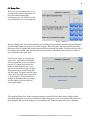
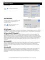
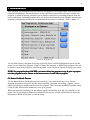
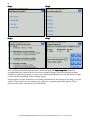
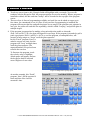
P-1000 Flaming/Brown Micropipette Puller System User Interface Manual Rev 1.12c (20131004) One Digital Drive Novato, CA 94949 Voice: 415-883-0128 Web: www.sutter.com Fax: 415-883-0572 Email: [email protected] ii Copyright © 2013 Sutter Instrument Company. All Rights Reserved. Flaming/Brown™ and Thermolock™ are trademarks of Sutter Instrument Company. P-1000 FLAMING/BROWN MICROPIPETTE PULLER USER INTERFACE MANUAL – REV. 1.12C (20131004) iii TABLE OF CONTENTS 1. Startup Screen................................ Screen................................................................ ................................................................................................ ................................................................................................ ............................................................................... ............................................... 1 2. Home Screen................................ Screen................................................................ ................................................................................................ ................................................................................................ .................................................................................. .................................................. 2 2.1 Opening a Program....................................................................................................................................... 2 2.2 Calibration of Touch Screen......................................................................................................................... 2 3. Pulling a Pipette ................................................................ ................................................................................................ ................................................................................................ ............................................................................ ............................................ 3 3.1 Pull Report ..................................................................................................................................................... 4 3.2 View Pull Results........................................................................................................................................... 4 3.3 Ramp Test ...................................................................................................................................................... 5 4. Menu Screen................................ Screen ................................................................ ................................................................................................ ................................................................................................ .................................................................................. .................................................. 6 4.1 Set Time & Date ............................................................................................................................................ 6 4.2 Lock Program ................................................................................................................................................ 6 4.3 Preheat Jaws 70°C (Thermolock™)............................................................................................................. 6 4.4 Air before Pull................................................................................................................................................ 6 4.5 Air after Pull .................................................................................................................................................. 6 5. Program List................................ List................................................................ ................................................................................................ ................................................................................................ .................................................................................. .................................................. 7 5.1 Sutter Cookbook Feature ............................................................................................................................. 7 6. Editing a Program................................ Program ................................................................ ................................................................................................ ................................................................................................ ......................................................................... ......................................... 9 6.1 Installing a Program ................................................................................................................................... 10 6.2 Patch Pipettes.............................................................................................................................................. 10 6.3 Microinjection Pipettes and High Resistant Electrodes (30-300 Megohm) .......................................... 10 6.4 Lock/Unlock Program................................................................................................................................. 10 6.5 Safe Heat Mode............................................................................................................................................ 11 6.6 Time & Delay Modes of Cooling ................................................................................................................ 11 6.7 Jaw Temperature ........................................................................................................................................ 12 6.8 Edit User Notes ........................................................................................................................................... 13 7. Error Messages during Pull ................................................................ ................................................................................................ ........................................................................................ ........................................................ 14 8. The Diagnostics Screen ................................................................ ................................................................................................ ............................................................................................... ............................................................... 15 8.1 Air Pressure System Diagnostics............................................................................................................... 15 8.1.1 Air Pressure Diagnostics Options....................................................................................................... 15 8.2 Heat Diagnostics.......................................................................................................................................... 16 8.3 Pull Diagnostics ........................................................................................................................................... 16 8.4 Velocity Diagnostics .................................................................................................................................... 17 9. Help Files ................................................................ ................................................................................................ ................................................................................................ ..................................................................................... ..................................................... 18 9.1 Glossary ........................................................................................................................................................ 18 9.2 Air System Diagnostics ............................................................................................................................... 18 9.3 Installing a Filament................................................................................................................................... 18 INDEX ................................................................ ................................................................................................ ................................................................................................ ............................................................................................. ............................................................. 19 P-1000 FLAMING/BROWN MICROPIPETTE PULLER USER INTERFACE MANUAL – REV. 1.12C (20131004) iv TABLE OF FIGURES Figure 1. Startup screen.............................................................................................................................1 Figure 2. Startup fault report screen........................................................................................................1 Figure 3. Home Screen. ..............................................................................................................................2 Figure 4. Pulling a pipette..........................................................................................................................3 Figure 5. Pull report. ..................................................................................................................................4 Figure 6. View the pull report....................................................................................................................4 Figure 7. Ramp test.....................................................................................................................................5 Figure 8. Ramp test result..........................................................................................................................5 Figure 9. Menu Screen................................................................................................................................6 Figure 10. Setting time and date...............................................................................................................6 Figure 11. Program List. ............................................................................................................................7 Figure 12. Single line looped program. .....................................................................................................9 Figure 13. Two-line program with first line looped.................................................................................9 Figure 14. Locking & unlocking a program (Menu screen)................................................................ 10 Figure 15. Items that cannot be changed in a locked program........................................................... 11 Figure 16. Time mode of air-cooling. ..................................................................................................... 11 Figure 17. Delay mode of air-cooling...................................................................................................... 12 Figure 18. Jaw temperature.................................................................................................................... 12 Figure 19. Edit user notes. ...................................................................................................................... 13 Figure 20. Diagnostics screen. ................................................................................................................ 15 Figure 21. Air-pressure system diagnostics........................................................................................... 15 Figure 22. Heat diagnostics..................................................................................................................... 16 Figure 23. Heat diagnostics fault conditions......................................................................................... 16 Figure 24. Pull diagnostics. ..................................................................................................................... 16 Figure 25. Velocity diagnostics. .............................................................................................................. 17 Figure 26. Help files................................................................................................................................. 18 Figure 27. Glossary. Figure 28. Glossary item detail........................................................................ 18 P-1000 FLAMING/BROWN MICROPIPETTE PULLER USER INTERFACE MANUAL – REV. 1.12C (20131004) 1 1. STARTUP SCREEN The power switch on your puller is located on the left side panel. When powering up the puller, the startup screen will display for 5 seconds. During this time, the puller systems are automatically tested. Figure 1. Startup screen. If a problem is detected during start up, a fault report, like the example below, will be displayed. In this case, you can go to the Diagnostics section (Page 15) to help test the system and find the problem, or you can press the Knob on the front panel to [Enter] and ignore the fault. If the error detected prevents the user from being able to operate the puller, please contact Sutter for assistance. Figure 2. Startup fault report screen. NOTE: The PP-1000 screen will go blank and into a Screensaver Mode after one hour. The green light around the Pull knob will slowly cycle on and off— off—pressing the [Pull] knob knob will WAKE the screen. P-1000 FLAMING/BROWN MICROPIPETTE PULLER USER INTERFACE MANUAL – REV. 1.12C (20131004) 2 2. HOME SCREEN The Home screen is where you select and open any of the 100 user programs. To install and open a program, use the touch screen keypad or the dial on the front panel. From the Home Screen you can either open a program or select one of the Options in the right column which provide access to the Menu, Menu the Program List, List the Sutter Cookbook, Cookbook, the Help Files, Files or Calibrate the Touch Screen. Blue text and numbers on the screen are actively touchsensitive. Green numbers or values are in the process of being installed or edited and are pending entry. To install a number that is in green text, press [Enter]. Black text is not touch sensitive. Figure 3. Home Screen. 2.1 Opening a Program For any single-digit program, enter the number on the touch screen and press [Enter] and it will open. A double-digit program will open automatically. Alternatively, you can use the knob on the front panel to dial and enter the program. 2.2 Calibration of Touch Screen In the case that the touch sensitive areas of the display do not function as expected or a misalignment has developed, it will be necessary to calibrate the touch screen. This is normally done from the Menu screen. If the screen does not respond, press RESET; RESET you can then calibrate from the Home screen. Follow the instructions, press [Enter] to start the calibration routine, and then press the green “saved” text in the middle of the screen to accept and save your calibration. P-1000 FLAMING/BROWN MICROPIPETTE PULLER USER INTERFACE MANUAL – REV. 1.12C (20131004) 3 3. PULLING A PIPETTE Open a Program Install the program number you would like to open and press [Enter] to open the program. Run a Ramp Test, Test or install known ramp value. (Ramp Test is described on Page 5). If the program is empty, a heat setting has not been installed, or no ramp value is recorded, you will be required to run a ramp test. Press [Ramp] and follow the instructions. The Safe Heat Mode will be on (default settings) and a ramp value needs to be installed into your program so the Safe Heat feature can help to protect your filament from burning out. The Safe Heat Mode will be described later in more detail. Install Parameter Settings To pull a pipette you will need to install the parameter values (heat, pull, velocity, time/delay, and pressure) or use a pre-installed program designed to pull a pipette for your application. Use Sutter Cookbook feature to find settings. If you are not sure what program to use, or do not know what parameter settings to install, please use the Sutter Pipette Cookbook feature found in the Menu or Home Screen where you can search for and install a predesigned program. Figure 4. Pulling a pipette. Pull a Pipette Once you have successfully run a ramp test, installed the ramp value and your parameter settings, load the appropriate glass and press [Pull]. During the pull, the progress will be displayed in the blue text box at the bottom of the display. You will see which Line or Loop is currently being executed. After the glass separates, the pull result is shown in summary. You will see the total number of Lines executed, the number of times the program Looped, the last Line number used when the glass separated, and the total Heat-On-Time. You can review the detailed results of the two most recent pulls by selecting [Menu] and then [View Pull Results] P-1000 FLAMING/BROWN MICROPIPETTE PULLER USER INTERFACE MANUAL – REV. 1.12C (20131004) 4 3.1 Pull Report The blue text box at bottom of the display shows the progress of the pull and then reports the final pull results. Figure 5. Pull report. 3.2 View Pull Results The Pull Results provides a means by which one can review the detailed results of a pull: Lines used, number of loops, and Heat-On-Time of the two most recent pulls. To review or compare the pull results, press [Menu] and then [View Pull Results] to view the report. Consistency of the Heat-On-Time and comparing the behavior of consecutive pulls can be useful tools in developing stable parameter settings. Figure 6. View the pull report. P-1000 FLAMING/BROWN MICROPIPETTE PULLER USER INTERFACE MANUAL – REV. 1.12C (20131004) 5 3.3 Ramp Test Here you can run a Ramp Test, or, if you know the current ramp value for this exact filament and glass combination, you can install it at this time. Otherwise, run a new ramp test. Figure 7. Ramp test. During a Ramp Test, the current delivered to the filament will gradually increase until the filament is hot enough (bright orange glow) to soften the glass. When the glass softens, the puller bars will drift apart ever so slightly and this movement will be detected by the puller. The heat will turn off at this stage and the ramp value will be reported on the screen. The Ramp Test is the level (units) of heat required to melt your glass. You have the option to [Accept] the ramp value, upon which is installed into your program, or you can repeat the test. To repeat, first loosen the knobs to slide the glass into a new location or install a new piece of glass. Then press repeat and the ramp test will run again. To ignore the new ramp value, press the back arrow to go back to your program. If there has been a change in the ramp value, you might need to adjust your heat values to reflect this change. Figure 8. Ramp test result. The resulting Ramp Test Value is an ideal setting to install for your Heat setting. Keep the Safe heat Mode turned on to protect your filament. Heat settings 10% over or under the Ramp Value are both unstable and can cause damage to your filament and, when installed, will cause a warning. P-1000 FLAMING/BROWN MICROPIPETTE PULLER USER INTERFACE MANUAL – REV. 1.12C (20131004) 6 4. MENU SCREEN Touch any of the blue titles in this menu to open that option. Press screen. to return to the previous Figure 9. Menu Screen. 4.1 Set Time & Date The date and time set in your puller is used to “time-stamp” a program when it is installed or edited. Press when you are ready to save your settings of date and time. Figure 10. Setting time and date. 4.2 Lock Program Press next to “Lock Program” to lock the current program. A locked program cannot be edited or nor cleared. To unlock the current Program, touch the box next to “Lock Program” and uncheck it. 4.3 Preheat Jaws 70°C 70°C (Thermolock™) (Thermolock™) Press next to “Preheat Jaws 70°C” to enable Thermolock mode for the current program. This feature preheats the jaws to 70°C and maintains that temperature throughout the pulling process. While in Thermolock mode, the pulling conditions in a multi-stage program are regulated so that the tip sizes, taper lengths, and cone angles of resulting pipettes are more consistent between pulls. To disable Thermolock mode for the current program, press the box next to “Preheat Jaws 70°C” to uncheck it. 4.4 Air before Pull This is the duration of time before the pull that the Humidity Control Chamber surrounding your filament is purged with dry air. This helps to remove humidity and control for the ambient conditions in your lab. The default setting is 5 seconds. Time settings between 5-20 seconds are reasonable. 4.5 Air after Pull This is the duration of time after the pull that the Humidity Control Chamber surrounding your filament is purged with dry air. This helps to remove humidity and control for the ambient conditions in your lab. The default setting is 5 seconds. Time settings between 5-20 seconds are reasonable. P-1000 FLAMING/BROWN MICROPIPETTE PULLER USER INTERFACE MANUAL – REV. 1.12C (20131004) 7 5. PROGRAM LIST Each program has associated notes and this text will appear in the Program Edit Screen when that program is highlighted. The detailed notes (if any) that have been written can help to identify the program: to whom it belongs, and what type of pipette it will pull. Pre-installed programs from the factory and Sutter Cookbook programs have pre-written notes that detail the filament and glass the program is intended for and lists the recommended heat setting, for example, “Heat = Ramp + 5” Figure 11. Program List. Use the Dial to bring a Program to the top of the List where it will be highlighted in green. At this stage, you can [Open] the program, [Copy] & [Paste] the program, or [Delete] the program. You will be asked to press [delete] again to clear the program, or you can press [Cancel] if change your mind. NOTE: If a program has been LOCKED, you cannot delete the program or copy & paste a program into that program location. Return to the menu screen to Lock/Unlock a program. 5.1 Sutter Cookbook Feature Feature Use the Sutter Pipette Cookbook feature to search for, select and install one of over 100 predesigned programs stored in the P-1000. After installing a program and pulling a pipette, you can adjust the settings to modify and fine-tune the program. There are many standard Programs stored on the P-1000, which can be modified to serve your purpose. When you open the Cookbook, you are asked to specify the filament type and size installed in your puller. The 2.5 x 2.5mm box filament is installed at the factory, and you will be asked to select the dimensions (OD/ID) of the glass you will be using. P-1000 FLAMING/BROWN MICROPIPETTE PULLER USER INTERFACE MANUAL – REV. 1.12C (20131004) 8 Step 1 Step 2 Step 3 Step 4 Once you have selected a program number, install the program, run a ramp test, test install the recommended heat (found in the blue text box) and pull a pipette. While the cookbook program should be a good starting point, you may need to make small adjustments to the parameter settings to fine-tune the morphology of the resulting pipette. If the program you have installed is not working, adjustments to the settings do not help, or you are unable to find a match for your filament size, glass size, or pipette application (pipette “Type”), please contact Sutter Instrument for technical help. P-1000 FLAMING/BROWN MICROPIPETTE PULLER USER INTERFACE MANUAL – REV. 1.12C (20131004) 9 6. EDITING A PRO GRAM Touch any screen item to edit. Numeric fields will highlight with a rectangle. You can edit numbers with the Keypad or Dial. All program settings are saved in memory. When a program is installed or edited, the date and time “stamp” will be recorded in the top right of the program screen. There are four (4) lines of programming available, and each line can be asked to repeat up to four times, for a maximum of ten (10) lines. If only one line of programming is installed, the program will execute that line and pull the pipette in one stage. If the glass does not separate in one cycle, the puller will read this line repeatedly, which is called “Looping” and pull the glass in multiple stages. If the program is appropriate for making a long microinjection needle or electrode (Pull > 40 and Vel > 50), the glass will separate in one stage. If the program is intended to pull a patch type pipette (Pull= 0 and Vel = 20-70), a one-line program, as exampled below, will execute in many stages or “Loops” until the glass separates. In this “Patch” program, Line 1 is asked to execute one time, but the program will “Loop” multiple times until the glass separates. The expected number of loops has been noted in the text box. To fine-tune the program, touch the velocity value to highlight (black square will appear) and use the keypad or knob to edit and enter a higher or lower value. Figure 12. Single line looped program. As another example, this “Patch” program, Line 1 will be executed 3 times and then Line 2 will be executed 1 time. Figure 13. Two-line program with first line looped. P-1000 FLAMING/BROWN MICROPIPETTE PULLER USER INTERFACE MANUAL – REV. 1.12C (20131004) 10 6.1 Installing a Program When pulling any type of pipette, it is best to first install a Cookbook program or a program you know worked well on a P-97 or P-1000 using the same glass and filament. Always run a new ramp test when installing a new program. If the program you install was established on a different puller with a different filament and/or glass size, you cannot expect the program to behave the same and make the same morphology of pipette. If your program parameters are established randomly or a specific setting is too high or too low, the program will be unstable and will not execute as expected. Please take note of the final pull report when pulling pipettes to make sure your program has executed properly. 6.2 Patch Pipettes Patch pipette programs are generally one line programs with Pull = 0 and Velocity = 15-60 that loop 2-5 times. The number of Loops (cycles) the puller performs is determined by the velocity setting. The number of Loops to aim for will depend on the glass size and type of patch experiment. Patch pipettes used for whole or dissociated cells cells usually require thick walled glass and a program that loops 4-6 times. Patch pipettes used for slice and live tissue usually require thin walled glass and a program that loops 1-3 times. To find a Cookbook program to make a patch pipette, press [Menu] or [Home] from the program screen. When in the Cookbook menu, you will be asked to select the filament and glass you are using. Then select a “Type A” program, which can then be installed and used to make a patch pipette. 6.3 Microinjection Pipettes and High Resistant Resistant Electrodes (30(30-300 Megohm) Megohm) These pipettes are commonly made by using a one-line program that pulls the glass apart in one stage. Use the Cookbook feature to help establish appropriate settings. Typical Pull and Velocity settings commonly used are Pull = 35-125 and Velocity = 50-90. To find a program from within the program screen, press [Menu] or [Home]. Type B and C Cookbook programs are best for making microinjection pipettes while Type C and D can be used to make high resistant electrodes. 6.4 Lock/Unlock Program The program can be locked/unlocked in the [Menu] screen. Figure 14. Locking & unlocking a program (Menu screen). P-1000 FLAMING/BROWN MICROPIPETTE PULLER USER INTERFACE MANUAL – REV. 1.12C (20131004) 11 A locked program will appear as shown in the next figure. When a program is locked, the keypad and clear button will disappear and you will be unable to change the parameter settings, the Air mode (Time/Delay), or change the Safe Heat Mode. To Unlock a program, go to the Menu and uncheck the “Lock Program” box. Figure 15. Items that cannot be changed in a locked program. 6.5 Safe Heat Mode If the “Safe Heat” is checked, the puller will “check” the heat setting in relation to the ramp value and will disallow heat settings that are 10% over or under the Ramp Test value. This helps to prevent unstable and unsafe heat settings that can damage the puller jaws or burn out the filament. If a ramp value is not present in your program, you will be required to run a ramp test or install a known ramp value for your glass and filament Heat Values 10% above or below the Ramp Test Value will cause a warning and disallow the entry. If this happens, you can adjust the heat to be within 5 units of the ramp test value, run a new ramp test, or turn off the Safe Heat Mode. If you turn off the Safe Heat Mode by unchecking the box, you take the risk of burning out your filament. 6.6 Time & Delay Modes of Cooling By checking and unchecking the “Delay Mode” checkbox, you can switch between Time and Delay, Delay which are the two “air modes”, used to cool the filament and glass during the pull. The Time mode allows you to determine the duration of air used to cool the glass. The Delay mode provides a set duration of cooling during which time you can determine when the hard pull will occur within the cooling stage. The Delay mode provides more cooling than the Time mode and helps to further control the viscosity of the glass as it is pulled. An example of the TIME mode of air-cooling is shown in the following figure. The Time Mode is recommended when using thin walled glass. Figure 16. Time mode of air-cooling. P-1000 FLAMING/BROWN MICROPIPETTE PULLER USER INTERFACE MANUAL – REV. 1.12C (20131004) 12 An example of the DELAY mode of air-cooling is shown in the following figure. Figure 17. Delay mode of air-cooling. The Delay Mode is recommended when additional cooling and more control over the viscosity of glass is required. The Delay Mode is often used for the following applications: Patch Pipettes using Thick Walled Glass Short microinjection needles for Adherent Cell Microinjection Pronuclear Injection pipettes 6.7 Jaw Temperature The jaw temperature is displayed at the end of pull and can be used to help define the best pulling conditions for making your pipettes. Therefore, for example, you might find that your pipettes are best formed when the jaw temperature is between 52 and 58 degrees Centigrade. If the jaw temperature exceeds 125 degrees Centigrade, a warning will be displayed and the puller will shut down. This “shut down” protects the puller and filament assembly from damage due to overheating. When the jaws have sufficiently cooled, you can proceed to pull pipettes. Figure 18. Jaw temperature. P-1000 FLAMING/BROWN MICROPIPETTE PULLER USER INTERFACE MANUAL – REV. 1.12C (20131004) 13 6.8 Edit User Notes By touching the blue text box at the bottom of your program you can bring up the “Edit User Notes” Screen. Figure 19. Edit user notes. Here you can edit the notes, press [Undo] to start over, or [Clear] all text and write your own notes. Pre-installed factory programs (0-5) and any programs imported from the Cookbook feature will have pre-written text notes detailing the filament, glass, pipette type and appropriate heat to use with that program. Take caution before clearing all text, as you might want to retain some information already describing this program. If the notes no longer apply to your program, clear all text and write your own notes. The “Notes” section is a good place to record whose program it belongs to, the filament type (box or trough), the glass size (OD/ID), and the application for which the program was designed. You might also want to record the heat setting you are using in relation to the Ramp Value. For example: Heat = Ramp +10. The Rotary Dial allows cursor movement through the text. Cursor position is indicated by the character in which the cursor is positioned turning green. P-1000 FLAMING/BROWN MICROPIPETTE PULLER USER INTERFACE MANUAL – REV. 1.12C (20131004) 14 7. ERROR MESSAGES DURIN G PULL Allow Jaws to cool cool below 100°C. 100°C. Pull temporarily inactivated. The jaws have overheated due to excessive and continuous use and you risk melting the black nylon backing. Wait for filament jaws to cool and/or call Sutter for technical help. Maximum 10 Program Lines. There are too many lines in your Program. A program with more than 6 lines or six loops can introduce variability. Edit your program, using the cookbook feature to find new settings, or call Sutter for technical support. Puller bars are separated. ReRe-clamp glass. Then press PULL again. The puller Bars must be drawn all the way together. Check that the puller bars are free to travel all the way to the center. If the puller bars are held back and are not free to move, press the outer metal spring locks to free up the puller bars. Line 1 Heat = 0. Install a heat setting. Lines with Heat = 0’. Please edit these lines. Install a heat setting or erase this line of programming. When Safe Heat is checked, A Ramp Value must be installed and the Heat setting must be within 10% of the Ramp test Value. Ramp = 0, Unable to Heat Check. Press Ramp or uncheck Safe Heat (at your own risk). Line 1 Heat > Ramp + 10%. Filament may burn out. Reduce Heat or run Ramp Test, or uncheck Safe Heat (at your risk). Line 1 Heat Heat < Ramp - 10%. Jaws may overheat. Increase Heat or run Ramp Test, or uncheck Safe Heat (at your risk). Heat current error. Is Filament present & intact? See Menu/Diagnostics if Filament is OK. Filament Heater current is not behaving correctly. Make sure the filament is installed and is not burned out or broken. Check the filament clamp screws to make sure they are tight. Failed to reach pressure There may be an air leak or other problem. Go to Menu/Diagnostics to determine. Also, see Home/Help Files/ Air system diagnostics to trace leaks. Failed to melt glass. This message shows if the glass does not soften after 60 seconds of heating. The Filament may have burned out (go to Menu/Diagnostics) or the Heat value may be too low. Perform a Ramp Test and use Safe Heat mode. P-1000 FLAMING/BROWN MICROPIPETTE PULLER USER INTERFACE MANUAL – REV. 1.12C (20131004) 15 8. THE DIAGNOSTICS SCRE EN In this screen, each piece of P-1000 hardware can be operated and tested independently. The purpose is to facilitate calls to Sutter Tech Support, but the more technically wellinformed user can perform their own tests. Using the Diagnostics, you can independently test the Air, Heat, Pull, and Velocity Sensor. See the following pages for detailed instructions. Figure 20. Diagnostics screen. 8.1 Air Pressure System Diagnostics The Pressure value is always highlighted for editing with the Dial. Press [Enter] to set. Figure 21. Air-pressure system diagnostics. 8.1.1 Air Pressure Diagnostics Options Run the pump unregulated to verify that the pump works. You will hear the pump running and note that the pressure transducer is increasing. Please note that you can increase the air pressure beyond its normal working range. Turning on the Automatic Pressure is a test of the Air Pump, the regulating circuitry, and air leakage from the system. Opening the Air Valve should cause the Pressure Transducer reading to drop. In a Leak Test, the pressure is raised to 500, and then measured for 10 seconds with the Pump off. An error is reported if the pressure drops more than 6 units. You can Trace and Correct leaks by following the instructions in this Help File topic. P-1000 FLAMING/BROWN MICROPIPETTE PULLER USER INTERFACE MANUAL – REV. 1.12C (20131004) 16 8.2 Heat Diagnostics Diagnostics To start Heat Circuit Test, press Enter. The Heat will be tested at a value of 200 for 10 seconds and the FETs (field-effect transistors) that control the heat current will be monitored. If the FET readings are unequal, there is a circuit board fault and you need to contact Sutter. If the FET readings are both lower than the Heat setting, the Heat current is low. This can be due to a circuit board fault. If both FET readings are [0], the filament could be missing or broken. Figure 22. Heat diagnostics. Fault conditions are reported in red after the test. The temperatures of the Brass Jaws that hold the filament and the internal heat sink are continuously displayed. If Jaw Temperature exceeds the maximum allowed, the Heat will automatically be turned off to avoid damage to the nylon mounting block. If the internal heat sink temperature exceeds its maximum, a RESET will occur. Figure 23. Heat diagnostics fault conditions. 8.3 Pull Diagnostics The Pull value is highlighted for editing. Figure 24. Pull diagnostics. P-1000 FLAMING/BROWN MICROPIPETTE PULLER USER INTERFACE MANUAL – REV. 1.12C (20131004) 17 WARNING: WARNING: A maximum setting of 255 is possible, but not recommended since this force force is very strong and can cause injury if your fingers or hands are in the path of the puller bars. 1. Use the Knob on the front panel to Dial in a setting of 75-100 units of pull and press [Enter]. 2. Place a small thin rubber band around the puller bar knobs to hold the puller bars together. The pull test will not work if the puller bars are apart. WARNING: To avoid injury, do do not use your fingers to hold the puller bars together. CAUTION: To avoid equipment or glass damage, never never clamp a piece of glass to test Pull. Pull. 3. Press the [Pull] button on the front panel and the puller bars will pull apart. Keep your hands out of the way. 4. The end of travel sensor will read “Tripped” when the puller bars are pulled apart and will read “Not tripped” when the puller bars are together. 5. If a hard pull does not occur, contact Sutter for technical help. 8.4 Velocity Diagnostics The Velocity value is always highlighted for editing. Use the Knob on the front panel to adjust this value and pres [Enter] to set. Figure 25. Velocity diagnostics. Hold the puller bars together with your fingers and gradually release them. When the Puller Bars move apart, a signal is generated. The velocity transducer will detect this movement, and briefly indicate, “tripped” on the display. The level of this signal is dependent on the speed of separation of the puller bars and you will notice a difference in sensitivity to movement at higher or lower settings. The Velocity setting is the threshold value at which the Trip occurs. The Background Velocity serves to calibrate the true zero reading. It is typically 1-2 units. This calibration is done automatically at each pull. The End of Travel sensor shows “Tripped” when the bars are apart and will read “Not Tripped” when the puller bars are fully together. P-1000 FLAMING/BROWN MICROPIPETTE PULLER USER INTERFACE MANUAL – REV. 1.12C (20131004) 18 9. HELP FILES The following screen shows the items that are available under Help Topics. Figure 26. Help files. 9.1 Glossary The Glossary is a list of topics for the P-1000 and pipette pulling terminology. Use the Dial to scroll up or down and Press the knob to [Enter]. Figure 27. Glossary. Figure 28. Glossary item detail. There is a definition, and sometimes an image or illustration with each term in the Glossary. The words in blue texts are links to an associated topic. You can browse back and forth using the links or press or Return to List. 9.2 Air System Diagnostics These help in tracing and correcting air leaks. If a leak can be traced to a user accessible part you can fix it. If the leak is internal or if the Air Valve is faulty, you will be advised to call Sutter Tech Support for further assistance. 9.3 Installing a Filament Here you can follow the systematic instructions on how to replace or install a filament. Images are provided, and if additional assistance is needed, please contact Sutter for technical help. P-1000 FLAMING/BROWN MICROPIPETTE PULLER USER INTERFACE MANUAL – REV. 1.12C (20131004) 19 INDEX A M Air after Pull ...................................................................6 Air before Pull.................................................................6 Air Pressure Diagnostics Options ...............................15 Air Pressure System Diagnostics ................................15 Air System Diagnostics ................................................18 Menu Screen ...................................................................6 Microinjection Pipettes ................................................10 C Calibration of Touch Screen ..........................................2 O Open a Program .............................................................3 Opening a Program ........................................................2 P Editing a Program ..........................................................9 Error Messages .............................................................14 Patch Pipettes.........................................................10, 12 Preheat Jaws 70°C..........................................................6 Program List ...............................................................2, 7 Pull a Pipette...................................................................3 Pull Diagnostics ............................................................16 Pull Report ......................................................................4 Pulling a Pipette .............................................................3 G R Glossary .........................................................................18 Ramp Test ...........................................................5, 11, 14 Run a Ramp Test............................................................3 D Diagnostics Screen........................................................15 E H Heat Diagnostics...........................................................16 Help Files............................................................ 2, 14, 18 High Resistant Electrodes ...........................................10 Home Screen ...............................................................2, 3 I Install Parameter Settings.............................................3 Installing a Filament ....................................................18 Installing a Program ....................................................10 J Jaw Temperature .................................................. 12, 16 S Safe Heat Mode.........................................................3, 11 Set Time & Date .............................................................6 Startup Screen ................................................................1 Sutter Cookbook .....................................................2, 3, 7 Sutter Cookbook Feature ..............................................7 T Thermolock™ ..................................................................6 Time & Delay Modes of Cooling..................................11 U L unlock program.............................................................11 User Notes.....................................................................13 Lock Program..................................................................6 lock/unlock program.....................................................10 V Velocity Diagnostics .....................................................17 View Pull Results........................................................3, 4 P-1000 FLAMING/BROWN MICROPIPETTE PULLER USER INTERFACE MANUAL – REV. 1.12C (20131004)