1
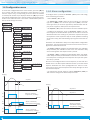
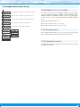
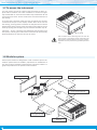
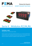
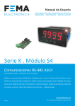
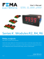
User’s Manual
ELECTRONICS
FOR
INDUSTRIAL
AUTOMATION
PANEL METERS . SIGNAL CONVERTERS . LARGE DISPLAYS
Series K . Modules R2, R4, R6
Relay outputs
PANEL meters . OPTIONAL control modules
Special relay output modules for K Series panel meters, with 2, 4 and 6 relay outputs. Relays with 3
contacts each (NC, NO, common). Switching up to 250 V @ 6 A continuous. Terminal with 3.81 mm
pitch. Configurable activation and deactivation delays, hysteresis, double setpoint, ...
www.fema.es
3551r01
Tel. (+34) 93.729.6004 [email protected]
FEMA ELECTRÓNICA . Series K . Modules R2, R4, R6
1. Modules R2, R4, R6
Modules with 2, 4 and 6 relays
Modules with 2, 4 and 6 relay outputs for K Series panel meters. Relays with 3 contacts each, with switching capability up to 250 V @ 6 A.
The R2, R4 and R6 modules provide setpoint configuration, hysteresis, independent activation and deactivation delays, and second
alarm setpoint for windowed alarms.
Modules R2, R4 and R6 are installed on slot ‘Opt.1’ (see section 1.8)
and are configured from instruments front keypad.
Only one module R2, R4 or R6 can be installed per instrument. Modules R2, R4 and R6 are not compatible with standard R1 modules.
Index
1.2 How to install the R2, R4, R6 modules
1. Modules R2, R4, R6 . . . . . . . . . . . . . . . . . . . . . . . 2
1.1 How to order . . . . . . . . . . . . . . . . . . . . . . . . . 2
1.2 How to install the R2, R4, R6 modules . . . . . . . . . . . 2
1.3 Technical specifications . . . . . . . . . . . . . . . . . . . 2
1.4 Rear view and connections . . . . . . . . . . . . . . . . . 3
1.5 Front view . . . . . . . . . . . . . . . . . . . . . . . . . . 3
1.6 Configuration menu . . . . . . . . . . . . . . . . . . . . . 4
1.6.1 Alarm configuration . . . . . . . . . . . . . . . . . . . 4
1.6.2 Alarms 1, 2, 3, 4, 5 and 6 . . . . . . . . . . . . . . . . 5
1.6.3 Factory reset . . . . . . . . . . . . . . . . . . . . . . . 5
1.6.4 Firmware version . . . . . . . . . . . . . . . . . . . . 5
1.7 To access the instrument . . . . . . . . . . . . . . . . . . 6
1.8 Modular system . . . . . . . . . . . . . . . . . . . . . . . 6
1.9 Precautions on installation . . . . . . . . . . . . . . . . . 7
1.10 Factory configuration . . . . . . . . . . . . . . . . . . . 7
1.11 CE declaration of conformity . . . . . . . . . . . . . . . 7
1.12 Warranty . . . . . . . . . . . . . . . . . . . . . . . . . . 7
To install a R2, R4 or R6 module into a K Series panel meter :
1. open the instrument housing (see section 1.7)
2. install the module at slot ‘Opt.1’ (see section 1.8) and close the
instrument
3. configure the module as indicated in the ‘Configuration menu’
(see section 1.6)
4. connect the signal terminals (see section 1.4)
1.1 How to order
1.3 Technical specifications
To order pre-installed R2, R4 or R6 modules into K Series panel meters, see the ‘How to order’ section into the panel meter user’s manual, for information on how to build the order reference.
To order standalone R2, R4 or R6 modules, for delayed installation
into K Series panel meters, use the following ordering references :
‘BK-R2’, ‘BK-R4’ or ‘BK-R6’
Slots allowed
‘Opt.1’ (see section 1.8)
• Module R2
occupies Opt.1
• Module R4
occupies Opt.1 and Opt.2
• Module R6
occupies Opt.1, Opt.2 and Opt.3
Number of relays
2 with module R2
4 with module R4
6 with module R6
Type of relay
3 contact relay (NC, NO, common)
Current maximum
6 A per relay (resistive load)
Voltage maximum*
250 Vac continuous
Isolation
2500 Veff
Type of terminal
plug-in screw terminal
pitch 3.81 mm
* terminals approved for 300 V (according to UL1059, groups B and
D) and 160 V (according to VDE on CAT-III and pollution degree 3).
2
The R2, R4 and R6 modules can be ordered pre-installed into a K
Series panel meter, or standalone for delayed installation, as they do
not require soldering or special configuration.
FEMA ELECTRÓNICA . Series K . Modules R2, R4, R6
1.4 Rear view and connections
1.5 Front view
Alarm leds
Opt.1
Opt.2
GHIJKL
MNOPQR
Opt.3
A B CD E F
Signal
Units
Power
Relay
Common
Normally Open
(NO)
Normally Closed
(NC)
relay 1
A
B
C
relay 2
D
E
F
relay 3
G
H
I
relay 4
J
K
L
relay 5
M
N
O
relay 6
P
Q
R
Table 1 - Connections for modules R2, R4 and R6
Detail of the plug-in screw terminals provided with
the instrument. The instrument is provided with all
terminals needed, both male and female.
3
FEMA ELECTRÓNICA . Series K . Modules R2, R4, R6
1.6 Configuration menu
To access the ‘configuration menu’ of the module, press the [<] key
for 1 second, and then move through the menu with the [5] key
until the ‘Opt.X’ entry, corresponding to the slot were the module
is installed (see section 1.8) is displayed. Press the [<] key to access
the module configuration menu. See the ‘How to operate the menus’
section in the instrument user’s manual for a detailed description on
how to move through the menus.
Alarm 1
1.6.1 Alarm configuration
To configure alarm 1, access the ‘Alarm 1’ (‘ALr1’) menu and configure the following parameters :
• select ‘Active’ (‘Act’) to ‘on’
• at ‘Alarm type’ (‘TypE’) select the alarm acting as a maximum
type alarm (‘MAX’) or a minimum type alarm (‘MIn’). The maximum type alarm (or minimum type alarm) activates when the display value is higher (or lower) than the setpoint value.
• at ‘Setpoint’ (‘SEt’) enter the value for the alarm activation point.
Active
• configure the hysteresis value at ‘Hysteresis’ (‘hySt’). The hysteresis applies to the deactivation process of the alarm. The alarm
deactivates when the reading has passed the setpoint value plus
the hysteresis value. Hysteresis helps to avoid repetitive switching
of the alarm relays, due to fluctuating input signals around the setpoint.
Alarm type
Setpoint
Activation and deactivation delays have independent configuration
parameters. They are expressed in tenths of second and can be configured from 0.0 to 99.9 seconds.
Hysteresis
• at ‘Delay 0’ (‘dEL.0’) configure the activation delay. The activation
delay will delay the activation of the alarm. The activation delay
starts counting when the setpoint value is passed.
Delay 0
• at ‘Delay 1’ (‘dEL.1’) configure the deactivation delay. The deactivation delay will delay the deactivation of the alarm. The deactivation delay starts counting when the setpoint value plus the hysteresis value, is passed.
Delay 1
Alarms can be configured with a second setpoint, to work with windowed alarms. The first setpoint activates the alarm, and the second
setpoint deactivates the alarm (configuration for ‘Alarm as maximum’ type of alarm). Second setpoint must always be higher in value
than the first setpoint.
Setpoint 2
• to activate the second setpoint, activate ‘Setpoint 2’ (‘SEt2’) to
‘on’ and then configure the desired setpoint value.
Reading
set point
hysteresis
Reading
set point 2
Time
off
Time
Time
on
off
activation
delay
on
off
4
set point 1
Alarm as maximum,
no hysteresis, no delays
on
Alarm as maximum,
with hysteresis and delays
Time
deactivation
delay
on
off
Alarm as minimum,
no hysteresis, no delays
Time
Alarm as minimum,
with double setpoint,
no hysteresis, no delays
Time
FEMA ELECTRÓNICA . Series K . Modules R2, R4, R6
1.6 Configuration menu (cont.)
1.6.2 Alarms 1, 2, 3, 4, 5 and 6
Menu for Alarm 2. Available in modules R2, R4 and R6
Menu for Alarm 3. Available in modules R4 and R6
Menu for Alarm 4. Available in modules R4 and R6
To configure alarm 1, enter the ‘Alarm 1’ (‘ALr1’) menu (see section
1.6.1). Menus ‘Alarm 2’ (‘ALr2’), ‘Alarm 3’ (‘ALr3’), ‘Alarm 4’ (‘ALr4’),
‘Alarm 5’ (‘ALr5’) and ‘Alarm 6’ (‘ALr6’) control the configuration
for alarms 2, 3, 4, 5 and 6 and are identical to the ‘Alarm 1’ (‘ALr1’)
menu.
Module ‘R2’ provides alarms 1 y 2.
Menu for Alarm 5. Available in modules R6
Menu for Alarm 6. Available in modules R6
Module ‘R4’ provides alarms 1, 2, 3 and 4.
Module ‘R6’ provides alarms 1, 2, 3, 4, 5 and 6.
1.6.3 Factory reset
Factory reset
At the ‘Factory reset’ (‘FAct’) menu, select ‘yes’ to load the default
factory configuration for the instrument (see section 1.10).
Version
1.6.4 Firmware version
The ‘Version’ (‘VEr’) menu informs of the current firmware version
installed in the module.
5
FEMA ELECTRÓNICA . Series K . Modules R2, R4, R6
1.7 To access the instrument
You may need to access the inside of the instrument to add or replace internal modules. Use a flat screwdriver to unlock the upper
clips marked with ‘A’. Then unlock the lower clips marked with ‘B’ and
remove the front cover. Let the inside of the instrument slide out of
the housing.
To reinsert the instrument make sure that all modules are correctly
connected to the pins on the display module. Place all the set into
the housing, assuring that the modules correctly fit into the internal
guiding slides of the housing. Once introduced, place again the front
cover by clipping first the upper clips ‘A’ and then the lower clips ‘B’.
Important - If your instrument was delivered with the IP65 front
seal option, accessing the inside of the instrument will permanently
break the IP65 seal on the areas of clips ‘A’ and ‘B’.
A
B
Risk of electric shock. Removing the front cover will
grant access to the internal circuits. Disconnect the
input signal to prevent electric shock to the operator.
Operation must be performed by qualified personnel
only.
1.8 Modular system
K Series panel meters are designed to create a modular system. This
modular system allows for addition, replacement or substitution of
any of the internal modules conforming the instrument. Below is a
graphic explanation for the position of each module.
Front Filter
Display Module
Optional Control Modules
Opt.2
Opt.1
Power Supply Module
Opt.3
Input Signal Module
Housing
6
FEMA ELECTRÓNICA . Series K . Modules R2, R4, R6
1.9 Precautions on installation
Risk of electrical shock. Instrument terminals can be connected to dangerous voltage.
Instrument protected with double isolation. No earth connection required.
Instrument conforms to CE rules and regulations.
This instrument has been designed and verified conforming to the
61010-1 CE Security Regulation, for industrial applications.
Installation of this instrument must be performed by qualified personnel only. This manual contains the appropriate information for
the installation. Using the instrument in ways not specified by the
manufacturer may lead to a reduction of the specified protection
level. Disconnect the instrument from power before starting any
maintenance and / or installation action.
1.11 CE declaration of conformity
Manufacturer
FEMA ELECTRÓNICA, S.A.
Altimira 14 - Pol. Ind. Santiga
E08210 - Barberà del Vallès
BARCELONA - SPAIN
www.fema.es - [email protected]
Products Modules R2, R4 and R6
The manufacturer declares that the instruments indicated comply with the
directives and rules indicated below.
Directive of electromagnetic compatibility 2004/108/CEE
Directive of low voltage 73/23/CEE
Security rules 61010-1
Emission rules
61000-6-4 Generic rules of emission
Immunity rules
61000-6-2
Generic rules of immunity
61000-4-2
By contact ±4 KV - Criteria B
By air ±8 KV - Criteria B
61000-4-3 Criteria A
61000-4-4 On signal lines : ±1 KV - Criteria B
61000-4-6Criteria A
61000-4-830 A/m a 50 Hz - Criteria A
Barberà del Vallès November 2012
Daniel Juncà - Quality Manager
1.10 Factory configuration
Alarms 1, 2, 3, 4, 5 and 6
Active
Type
Setpoint 1
Setpoint 2
Setpoint 3
Setpoint 4
Setpoint 5
Setpoint 6
Hysteresis
Activation delay
Deactivation delay
Setpoint 2 on
as maximum
1000
2000
3000
4000
5000
6000
0 counts
0.0 seconds
0.0 seconds
Off
1.12 Warranty
This instrument is warranted against all manufacturing defects for a
period of 24 MONTHS from the shipment date. This warranty does
not apply in case of misuse, accident or manipulation by non-authorized personnel. In case of malfunction get in contact with your local
provider to arrange for repair. Within the warranty period and after
examination by the manufacturer, the unit will be repaired or substituted when found to be defective. The scope of this warranty is limited to the repair cost of the instrument, not being the manufacturer
eligible for responsibility on additional damages or costs.
7
Panel meters
Standard 96 x 48 mm
Panel meters
Miniature 48 x 24 mm
Signal converters
Panel meters
Compact 72 x 36 mm
Large format meters
Bar meters
Isolators
Low cost
‘Customized’
instruments
mA
Vac
TrueRMS
FEMA ELECTRÓNICA, S.A.
Altimira 14 - Pol. Ind. Santiga
E08210 Barberà del Vallès
BARCELONA - SPAIN
Vdc
Pt100
Tel. +34 93.729.6004
Fax +34 93.729.6003
[email protected]
www.fema.es
TC
Aac
Hz
TrueRMS
Vac
Aac
X/5
Vdc
Adc
X/1
Pt100
Pot
Shunts
MODBUS
Load
RS-485
RS-232
BCD
Custom
?