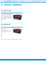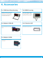
1
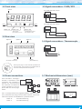
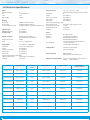
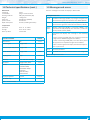
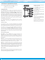
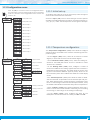
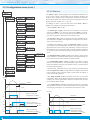
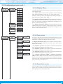
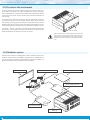
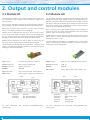
User’s Manual
ELECTRONICS
FOR
INDUSTRIAL
AUTOMATION
PANEL METERS . SIGNAL CONVERTERS . LARGE DISPLAYS
Series K . K40-T
Meter for temperature signals
PANEL meters
Panel meter for temperature signals, with 20 mm digit height. Accepts signals from Pt100 / RTD (2 and
3 wires) and thermocouples J, K, T, E, S, R, N, C, L and X. Reading configurable in ºC or ºF. Manual offset
configurable. Configurable cold junction compensation. Sensor break detection. Standard 96 x 48 mm
size (1/8 DIN). Reading with 4 digit display. Fast access to alarm setpoints, ‘on power up’ function,
configurable reading brightness. Universal AC and DC power. Up to 3 optional modules for output and
control (relays, analog outputs, Modbus RTU communications, RS-485 ASCII, RS-232, ...)
www.fema.es
3833r01
Tel. (+34) 93.729.6004 [email protected]
FEMA ELECTRÓNICA . Series K . K40-T
1. Panel meter K40-T
Panel meter 96 x 48 mm (1/8 DIN) for temperature signals, with 20 mm digit height
Panel meter 96 x 48 mm (1/8 DIN) for temperature signals, with
20 mm digit height. Accepts signals from Pt100 / RTD (2 and 3 wires)
and thermocouples J, K, T, E, S, R, N, C, L and X. Configurable reading
in º Celsius or º Fahrenheit. Thermocouple cold junction compensation configurable (see section 1.11.2). Configurable offset for display
reading (see section 1.11.2). Selectable behavior in case of sensor
break (see section 1.11.2). Reading with 4 digits and negative sign.
Options for output and control with 1, 2 and 3 relays, isolated analog
outputs, communications in Modbus RTU, RS-485 ASCII and RS-232.
Special options with 4 and 6 relay outputs.
Independent alarms configurable as maximum or minimum, with 1
or 2 setpoints per alarm, hysteresis, independent activation and deactivation delays and control for inverted relay.
Front protection IP54 with optional IP65. Connections by plug-in
screw terminals. For industrial applications.
• ‘Fast access’ menu to selected functions, accessible with key UP (5)
(see section 1.11.5)
• ‘On power up’ for system protection on first ‘cold’ start-up (see
section 1.11.7)
Display filters, memory for maximum and minimum reading, password protection, 5 brightness levels.
1.1 How to order
Model
K40
-
T
Power
-
H
-H
-L
(85-265 Vac/dc)
(11/60 Vdc,
24 Vac, 48 Vac)
Option 1
-
Option 2
-
-R1
-AO
-RTU
-S4
-S2
-
(1 relay)
(analog output)
(Modbus RTU)
(RS-485)
(RS-232)
(empty)
Option 3
-
Others
-NBT
-65
(no buttons)
(front IP65)
Index
1. Panel meter K40-T . . . . . . . . . . . . . . . . . . . . . . . . 2
1.1 How to order . . . . . . . . . . . . . . . . . . . . . . . . . 2
1.2 Front view . . . . . . . . . . . . . . . . . . . . . . . . . . 3
1.3 Rear view . . . . . . . . . . . . . . . . . . . . . . . . . . . 3
1.4 Power connections . . . . . . . . . . . . . . . . . . . . . 3
1.5 Signal connections - Pt100 / RTD . . . . . . . . . . . . . . 3
1.6 Signal connections - Thermocouple . . . . . . . . . . . . 3
1.7 Mechanical dimensions (mm) . . . . . . . . . . . . . . . 3
1.8 Technical specifications . . . . . . . . . . . . . . . . . . . 4
1.9 Messages and errors . . . . . . . . . . . . . . . . . . . . 5
1.10 How to operate the menus . . . . . . . . . . . . . . . . 6
1.11 Configuration menu . . . . . . . . . . . . . . . . . . . . 7
1.11.1 Initial set-up . . . . . . . . . . . . . . . . . . . . . . 7
1.11.2 Temperature configuration . . . . . . . . . . . . . . 7
1.11.3 Alarms . . . . . . . . . . . . . . . . . . . . . . . . . . 8
1.11.4 Display filters . . . . . . . . . . . . . . . . . . . . . . 9
1.11.5 Fast access . . . . . . . . . . . . . . . . . . . . . . . 9
1.11.6 Super fast access . . . . . . . . . . . . . . . . . . . . 9
1.11.7 Menu ‘On Power Up’ . . . . . . . . . . . . . . . . . 10
1.11.8 Menu ‘Key LE’ . . . . . . . . . . . . . . . . . . . . 10
1.11.9 Function ‘Password’ . . . . . . . . . . . . . . . . . 10
1.11.10 Factory reset . . . . . . . . . . . . . . . . . . . . 10
1.11.11 Firmware version . . . . . . . . . . . . . . . . . . 11
1.11.12 Brightness . . . . . . . . . . . . . . . . . . . . . . 11
1.11.13 Access to optional modules . . . . . . . . . . . . 11
2
1.12 Full configuration menu . . . . . . . . . . . . . . . . . 12
1.13 To access the instrument . . . . . . . . . . . . . . . . 14
1.14 Modular system . . . . . . . . . . . . . . . . . . . . . 14
1.15 Precautions on installation . . . . . . . . . . . . . . . 15
1.16 Factory configuration . . . . . . . . . . . . . . . . . . 15
1.17 Warranty . . . . . . . . . . . . . . . . . . . . . . . . . 15
1.18 CE declaration of conformity . . . . . . . . . . . . . . 15
2. Output and control modules . . . . . . . . . . . . . . . . . 16
2.1 Module R1 . . . . . . . . . . . . . . . . . . . . . . . . . 16
2.2 Module AO . . . . . . . . . . . . . . . . . . . . . . . . . 16
2.3 Module RTU . . . . . . . . . . . . . . . . . . . . . . . . 17
2.4 Module S4 . . . . . . . . . . . . . . . . . . . . . . . . . 17
2.5 Module S2 . . . . . . . . . . . . . . . . . . . . . . . . . 18
2.6 Modules R2, R4, R6 . . . . . . . . . . . . . . . . . . . . 18
3. Other options . . . . . . . . . . . . . . . . . . . . . . . . . 20
3.1 Option NBT . . . . . . . . . . . . . . . . . . . . . . . . . 20
3.2 Option 65 . . . . . . . . . . . . . . . . . . . . . . . . . 20
4. Accessories . . . . . . . . . . . . . . . . . . . . . . . . . . 21
4.1 THM benchtop housing . . . . . . . . . . . . . . . . . . 21
4.2 Adapter DRA-M . . . . . . . . . . . . . . . . . . . . . . 21
4.3 Adapter KA96 . . . . . . . . . . . . . . . . . . . . . . . 21
4.4 WME housing . . . . . . . . . . . . . . . . . . . . . . . 21
4.5 Protector KIP . . . . . . . . . . . . . . . . . . . . . . . . 21
FEMA ELECTRÓNICA . Series K . K40-T
1.2 Front view
1.5 Signal connections - Pt100 / RTD
Alarms
For Pt100 / RTD with 2 wires
1 2 3
Pt100 2 wires
Logo
Units
For Pt100 / RTD with 3 wires
1 2 3
Button ‘LE’
Button ‘UP’
Button ‘SQ’
‘Fast access‘
(see section 1.11.5)
‘Configuration menu’
(see section 1.10)
Pt100 3 wires
1.3 Rear view
Option 3
Option 1
Option 2
1.6 Signal connections - Thermocouple
1 2 3
+
1 2 3
Signal
(see section 1.5 and 1.6)
8 9 0
-
Power
(see section 1.4)
Detail of the plug-in screw terminals provided with
the instrument. The instrument is provided with all
terminals needed, both male and female.
1.4 Power connections
Earth connection - Although a
terminal is provided for earth
connection, this connection is
optional. The instrument does
not need earth connection for
correct operation nor for compliance with the security regulations.
1.7 Mechanical dimensions (mm)
890
48
~
+
~
-
Fuse - To comply with security regulation 61010-1, add to the power
line a protection fuse acting as disconnection element, easily accessible to the operator and identified as a protection device.
Power ‘H’ fuse 250 mA time lag
Power ‘L’
fuse 400 mA time lag
96
16
44
75
8
Panel
cut-out
92
3
FEMA ELECTRÓNICA . Series K . K40-T
1.8 Technical specifications
Thermocouples
resolution
ranges
max. error at 25 ºC
offset drift
span drift*
Digits
number of digits
4
led 7 segments led
colorred
digit height
20 mm
Reading
overrange underrange
in case of sensor break
9999 with flash reading
-1999 with flash reading
reading ‘to_high’ or ‘to_low’ (see section 1.11.2)
Signal ranges
Accuracy at 25 ºC
Thermal drift
(see Table 1)
(see Table 1)
(see Table 1)
Signals accepted
Pt100 / RTD (see Table 1)
thermocouples (see Table 1)
temperature scale
ITS90
units
ºC or ºF, configurable
Pt100 / RTD
2 or 3 wires, configurable
resolution
1º or 0.1º, configurable
ranges
(see Table 1)
max. error at 25ºC
(see Table 1)
offset drift
(see Table 1)
span drift*
(see Table 1)
(*span drift includes offset drift)
cable compensation
automatic up to 14 Ohms
readings
4 / second
Sensor
Range (en ºC)
Error max.
J, K, T, E, S, R, N, C, L and X
(thermocouple X is 10 uV/ºC linear signal)
1º
(see Table 1)
(see Table 1)
(see Table 1)
(see Table 1)
(*span drift includes offset drift)
thermocouple CJC
cold junction accuracy
cold junction drift
readings
automatic (see section 1.11.2)
<1.0 ºC
<0.04 º/ºC
3 / second
Power
power ‘H’
power ‘L’
isolation*
consumption
85 a 265 Vac/dc
11 a 60 Vdc y 24/48 Vac
2500 Veff with power ‘H’
1500 Veff with power ‘L’
*all units tested during 60 seconds
<1.5 W only meter
<4.0 W meter with options
Configuration
3 buttons front keypad
(and rear jumper)
Front protection
IP54 standard
IP65 optional (see section 3.2)
Output and control options relays, analog outputs, serial communications, ... (see section 2)
Range (en ºF)
Offset drift
Pt100 / RTD
800 / -200 ºC
<0.2 ºC
1562 / -328 ºF
0.05 º/ºC
0.10 º/ºC
Thermocouple J
1200 / -200 ºC
<2 ºC
2192 / -328 ºF
0.05 º/ºC
0.20 º/ºC
Thermocouple K
1372 / -200 ºC
<2 ºC
2372 / -328 ºF
0.05 º/ºC
0.20 º/ºC
Thermocouple T
400 / -200 ºC
<2 ºC
752 / -328 ºF
0.02 º/ºC
0.02 º/ºC
Thermocouple E
1000 / -200 ºC
<2 ºC
1832 / -328 ºF
0.05 º/ºC
0.20 º/ºC
Thermocouple S
1768 / -50 ºC
<4 ºC
2282 / -58 ºF
0.20 º/ºC
0.20 º/ºC
Thermocouple R
1600 / -50 ºC
<4 ºC
2912 / -58 ºF
0.20 º/ºC
0.20 º/ºC
Thermocouple N
1300 / -200 ºC
<2 ºC
2372 / -328 ºF
0.05 º/ºC
0.20 º/ºC
Thermocouple C
2320 / 0 ºC
<2 ºC
4192 / 32 ºF
0.02 º/ºC
0.02 º/ºC
Thermocouple L
900 / -200 ºC
<2 ºC
1652 / -328 ºF
0.05 º/ºC
0.20 º/ºC
Thermocouple X
4000 / -200 ºC
<2 ºC
7232 / -328 ºF
0.02 º/ºC
0.02 º/ºC
Table 1 - Technical specifications for each sensor
4
Span drift*
*includes offset drift
at 25 ºC
FEMA ELECTRÓNICA . Series K . K40-T
1.9 Messages and errors
1.8 Technical specifications (cont.)
Mechanical
mounting connections
housing material weight front size
panel cut-out
depth from panel panel
plug-in screw terminal
ABS, polycarbonate (V0)
<150 grams
96 x 48 mm (1/8 DIN)
92 x 44 mm
91 mm (including terminals)
Temperature
operation storage warm-up time
from 0 to +50 ºC
from -20 to +70 ºC
15 minutes
Functions included
The error messages are shown on display in flash mode.
Messages and errors
‘h.oVr’
Hardware overrange (‘h.ovr’). Input signal is higher than
the maximum signal the instrument can detect (80 mV)
‘h.udr’
Hardware underrange (‘h.udr’). Input signal is lower than
the minimum signal the instrument can detect (-30 mV).
‘d.udr’
‘d.oVr’
display underrange (‘d.udr’) / overrange (‘d.ovr’). The
instrument already displays the minimum / maximum
value possible (-1999 / 9999).
‘brk’
instrument will display ‘brk’ message in the following
cases
• when measuring Pt100 / RTD, the resistance measured
is higher than 390 Ohms (higher than 850 ºC)
• when measuring Pt100 / RTD, the third wire (sense
wire) presents an impedance higher than 15 Ohms
• when measuring thermocouples, the thermocouple circuit is open circuit
‘Err.1’
incorrect password.
‘Err.2’
at ‘oPt.X’ menu entry. Installed module is not recognized.
Section
‘Fast access’
yes
1.11.5
Manual offset
configurable
1.11.2
Thermocouple cold junction configurable
1.11.2
Sensor break detection
configurable
1.11.2
Display filters
steps
1.11.4
Memory
max. and min. readings
1.11.4
Password
configuration block
1.11.9
Alarms
double setpoints
activation delays
deactivation delays
hysteresis
inverted relays
locked alarms
1.11.3
Display brightness
5 levels
1.11.12
‘On Power Up’
yes
1.11.7
Table 3 - Messages and error codes
Table 2 - Functions included
5
FEMA ELECTRÓNICA . Series K . K40-T
1.10 How to operate the menus
Example of operation inside the
‘configuration menu’.
The instrument has two menus accessible to the user :
‘Configuration menu’ (key SQ) (<)
‘Fast access’ menu (key UP) (5)
(1)
(6)
For a detailed explanation on the ‘configuration menu’ see section
1.10, and for a full view of the ‘configuration menu’ structure see
section 1.12.
‘Fast access’ menu
The ‘fast access’ menu is an operator configurable menu, providing
fast and direct access to the most usual functions of the instrument
with a single key pad stroke. Press key UP (5) to access this menu.
See section 1.11.5 for a list of functions eligible for ‘fast access’ in
this instrument. The ‘Password’ (‘PASS’) function does not block access to this menu. Accessing and modifying parameters in the ‘fast
access’ menu does not interfere with the normal functionality of the
instrument, and it does not generate any system reset when validating the changes.
Front key pad description
Key SQ (<) - press the SQ (<) key for 1 second to access the ‘configuration menu’. Inside the menu, the SQ (<) key functions as a
‘ENTER’ key. It selects and accesses the menu option currently displayed. At menus with numerical value entries, it validates the number displayed.
Key UP (5) - the UP (5) key gives access to the ‘fast access’ menu.
Inside the menus, it moves vertically through the different menu options. At menus with numerical value entries, it modifies the digit
selected by increasing its value to 0, 1, 2, 3, 4, 5, 6, 7, 8, 9.
Key LE (3) - inside the menus, the LE (3) key functions as the ‘ESCAPE’ key. It leaves the selected menu, and eventually, will leave the
whole menu. When leaving the ‘configuration menu’ with the LE (3)
key, the changed parameters are activated. At menus with numerical value entries, the LE (3) key allows to select the active digit. To
modify the value of the selected digit use the UP (5) key.
Menu ‘rollback’
After 30 seconds without interaction from the operator, the instrument will rollback and leave the ‘configuration menu’ or the ‘fast access’ menu. All changes will be discarded.
6
(4)
1. The SQ (<) key enters into the
‘configuration menu’.
(4)
2. The SQ (<) key enters into the
‘InP’ option menu.
(4)
3. The UP (5) key moves through
the menu options.
(5)
Configuration menu
The ‘configuration menu’ modifies the configuration parameters to
adapt the instrument to the application needs. To access the ‘configuration menu’ press for 1 second the SQ (<) key. This access can
be blocked by activating the ‘Password’ (‘PASS’) function. While
operating the ‘configuration menu’, the alarm status is ‘hold’ to the
status they had before accessing the menu, and the output and control modules remain in ‘error’ state. When leaving the ‘configuration
menu’, the instrument applies a system reset, followed by a brief
disconnection of the alarms and the output and control modules.
Functionality is then recovered.
(2)
(3)
Input
(3)
(5)
(3)
(5)
(3)
(4)
(5)
(6)
(3)
(3)
(3)
4. The SQ (<) key selects the
desired range and returns to the
‘InP’ menu.
5. The LE (3) key leaves the actual menu level and moves to the
previous menu level.
6. The LE (3) key leaves the ‘configuration menu’. Changes are applied and saved at this moment.
FEMA ELECTRÓNICA . Series K . K40-T
1.11 Configuration menu
Press ‘SQ’ (<) for 1 second to access the ‘configuration menu’.
For a description on how to operate inside the menus see section
1.10. For a full vision of the ‘configuration menu’ structure see
section 1.12.
To configure the initial set up of the instrument, select the type of
sensor to be connected to the instrument.
Access the ‘Input’ (‘InP’) menu to select the type of sensor. Options
available are Pt100 / RTD with 2 and 3 wires, and thermocouples J, K,
T, E, S, R, N, C, L and X. Thermocouple X is a linear signal os 10 uV/ºC.
Pt100 / RTD 2 wires
Input
1.11.1 Initial set-up
Pt100 / RTD 3 wires
Thermocouple J
Thermocouple K
Thermocouple T
Thermocouple E
Thermocouple S
Thermocouple R
Thermocouple N
Thermocouple C
1.11.2 Temperature configuration
Thermocouple L
The ‘Temperature configuration’ (‘cnF.t’) menu allows to configure
several functions associated to the measure and working with temperature signals.
Thermocouple X
Degrees Celsius
Temperature
configuration
Degrees
Degrees Fahrenheit
1º resolution
Resolution Pt100
0.1º resolution
Reading offset
Thermocouple
CJC
Reading to maximum
‘On break’
Reading to minimum
Alpha 385
Alpha
Alpha 390
• at the ‘Degree’ (‘dEG’) menu, select ‘ºc’ to measure in Celsius
degrees, or select ‘ºF’ to measure in Fahrenheit degrees.
• at the ‘Resolution Pt100’ (‘P.rES’) menu, select the reading resolution for the Pt100 / RTD. Select ‘1º’ for 1º resolution or select
‘0.1º’ for 0.1º resolution.
• at the ‘Reading offset’ (‘oFFS’) menu, configure a number of
counts to be added to the reading. Applies both to the measure in
Pt100 / RTD and thermocouples. This offset allows to correct reading errors associated to different types of probes, which can not
be corrected by other means. Offset value allows for ‘±100’ display
counts.
• the ‘Thermocouple CJC’ (‘t.cJc’) menu allows to active or deactivate the automatic compensation of the thermocouple cold junction. When working with a real thermocouple, compensation must
be on. In case of using an electronic thermocouple simulator, it may
be needed to deactivate the automatic cold junction compensation.
• at the ‘on break’ (‘on.bk’) menu select the behavior of the instrument in case of sensor break detection. Select ‘to_h’ to set reading
to overrange, or select ‘to_L’ to set reading to underrange.
• at the ‘Alpha’ (‘ALPh’) menu configure the alpha for the
Pt100 / RTD. The standard values in industry are ‘385’ and ‘390’.
7
FEMA ELECTRÓNICA . Series K . K40-T
1.11 Configuration menu (cont.)
1.11.3 Alarms
The ‘Alarms’ (‘ALr’) menu configures the independent activation of
up to 3 relay outputs, installed with the R1 optional modules (see
section 2.1). For outputs up to 4 and 6 relays, see special modules R2,
R4 and R6 at section 2.6. The alarm states are indicated in the front
display with leds marked as ‘1’, ‘2’ and ‘3’.
Alarms
Alarm 1
Active
To configure an alarm, enter into the alarm menu (‘ALr1’, ‘ALr2’ or
‘ALr3’) and configure the following parameters :
Alarm type
• select ‘Active’ (‘Act’) to ‘on’
• at ‘Alarm type’ (‘TypE’) select the alarm acting as a maximum
type alarm (‘MAX’) or a minimum type alarm (‘MIn’). The maximum type alarm (or minimum type alarm) activates when the display value is higher (or lower) than the setpoint value.
Setpoint
Hysteresis
• at ‘Setpoint’ (‘SEt’) enter the value for the alarm activation point.
This parameter is eligible for configuration through the ‘Fast access’
menu (see section 1.11.5).
Activation delay
• configure the hysteresis value at ‘Hysteresis’ (‘hySt’). The hysteresis applies to the deactivation process of the alarm. The alarm
deactivates when the reading has passed the setpoint value plus
the hysteresis value. Hysteresis helps to avoid repetitive switching
of the alarm relays, due to fluctuating input signals around the setpoint.
Deactivation delay
• at ‘Activation delay’ (‘dEL.0’) configure the delay to apply before
alarm activation. The activation delay starts counting when the setpoint value is passed. Value from 0.0 to 99.9 seconds.
Setpoint 2
• at ‘Deactivation delay’ (‘dEL.1’) configure the delay to apply
before alarm deactivation. The deactivation delay starts counting
when the setpoint value plus the hysteresis value, is passed. Value
from 0.0 to 99.9 seconds.
Relay inverted
Locked alarm
• to work with ‘windowed alarms’ (see graphical example below)
activate ‘Setpoint 2’ (‘SEt2’) to ‘on’ and then configure the desired
second setpoint value. Second setpoint must always be higher in
value than the first setpoint.
• the ‘Relay inverted’ (‘r.Inv’) parameter inverts the normal relay
connections. When set to ‘on’ the relay will be active when alarm is
inactive. For security applications where an inactive relay controls
the shutdown of the system.
Reading
setpoint
• the ‘Locked alarm’ (‘A.Lck’) parameter disables the automatic
deactivation of the alarm. Alarm deactivation must be performed
manually, by pressing the ‘LE’ front button (see section 1.11.8)
hysteresis
Time
Reading
Alarm as maximum,
no hysteresis, no delays
on
off
Setpoint 2
Time
Setpoint 1
on
off
activation
delay
on
off
8
Alarm as maximum,
with hysteresis and delays
Time
deactivation
Time
delay
Alarm as minimum,
no hysteresis, no delays
Time
on
off
Alarm as minimum,
with double setpoint,
no hysteresis, no delays
Time
FEMA ELECTRÓNICA . Series K . K40-T
1.11 Configuration menu (cont.)
1.11.4 Display filters
Display
The instrument provides several functions associated to the reading
of the display values
Steps
• the ‘Steps’ (‘StEP’) function allows to define minimum reading
steps, which will be done in steps of 1, 2, 5, 10, 20 or 50 counts.
Example - selecting a step of 20 configures the reading to change in
steps of 20 counts (‘1420’, ‘1440’, ‘1460’, ...).
• the ‘Memory of maximum’ (‘MAX’) function displays the maximum
reading value stored in memory. It also provides a way to reset the
value. This parameter is eligible for configuration through the ‘Fast
access’ menu (see section 1.11.5).
• the ‘Memory of minimum’ (‘MAX’) function displays the minimum
reading value stored in memory. It also provides a way to reset the
value. This parameter is eligible for configuration through the ‘Fast
access’ menu (see section 1.11.5).
Memory of
maximum
Memory of
minimum
1.11.5 Fast access
Tools
Key UP
(‘Fast access’)
Setpoint 1
Setpoint 2
Setpoint 3
Memory of
maximum
Memory of
minimum
The ‘UP’ (5) key at the front of the instrument gives access to a list
of functions configurable by the operator. See section 1.11.2 for an
explanation on how to operate the ‘fast access’ menu.
The ‘Key UP (Fast access)’ (‘K.uP’) menu allows to select which functions will be accessible through the ‘fast access’ menu. Select ‘on’ to
activate each function.
• the ‘Setpoint 1’ (‘ALr1’) function allows to visualize and modify the
alarm 1 setpoint through the ‘fast access’ menu.
• the ‘Setpoint 2’ (‘ALr2’) function allows to visualize and modify the
alarm 2 setpoint through the ‘fast access’ menu.
• the ‘Setpoint 3’ (‘ALr3’) function allows to visualize and modify the
alarm 3 setpoint through the ‘fast access’ menu.
• the ‘Memory of maximum’ (‘MAX’) or ‘Memory of minimum’
(‘MIn’) functions allow to visualize the maximum or minimum reading value stored in memory. To reset this value, visualize the memory
value at the ‘fast access’ menu with key UP (5) and when message
‘rSt’ is displayed, press (<) to reset.
1.11.6 Super fast access
If only a single function is selected for the ‘fast access’ menu, pressing the ‘UP’ (5) key will shortly display the function name and then
automatically jump to the function value.
9
FEMA ELECTRÓNICA . Series K . K40-T
1.11 Configuration menu (cont.)
1.11.7 Menu ‘On Power Up’
On Power-Up
Delay
Alarm 1
Alarm 2
Alarm 3
Seconds
The ‘On Power Up’ (‘on.Pu’) menu configures functions to apply at
start-up. It applies only to instrument restart after power loss. It does
not apply to instrument restart due to change in configuration.
• parameter ‘Delay’ (‘dLAy’) assigns a waiting time in seconds. The
instrument waits the configured time before starting normal function. During this waiting time, the display shows all decimal points
on in flash mode, all alarms are in the state defined at the ‘Alarm 1’,
‘Alarm 2’ and ‘Alarm 3’ entries, there is no signal acquisition and
there is no communications or control being performed. After the
configured time is over, the instrument starts in normal function. Delay value between 0 and 200 seconds.
Application - the start-up process for an automation system implies
that different parts of the system (engines, actuators, controllers, ...)
have different start-up times. The ‘Delay’ function gives time to the
instrument to wait until the slowest part of the system is fully functional before executing actions on the system (signal reading, relay
activation, ...)
• the ‘Alarm 1’ (‘ALr1’), ‘Alarm 2’ (‘ALr2’) and ‘Alarm 3’ (‘ALr3’) parameters allow to define the status of the alarms while the instrument is starting from a power loss. Select ‘on’ for active alarm, select
‘oFF’ for deactivated alarm.
1.11.8 Menu ‘Key LE’
Key LE
No function
Alarm unlock
The ‘LE’ (3) key at the front of the instrument can be configured to
activate several functions. Only one function can be assigned to the
‘LE’ (3) key
• the ‘No function’ (‘nonE’) value assigns no function.
• the ‘Alarm unlock’ (‘A.Lck’) value assigns the manual unlock of the
alarms function, for instruments with the ‘Locked alarms’ (‘A.Lck’)
function activated (see section 1.11.3)
1.11.9 Function ‘Password’
Password
At the ‘Password’ (‘PASS’) menu select a 4 digit code to block access
to the ‘configuration menu’. Instrument configuration will not be accessible to non authorized personnel. To activate the ‘Password’ select ‘on’ and introduce the code.
Factory reset
The code will be requested when trying to access the ‘configuration
menu’ (key ‘SQ’ (<)). The ‘fast access’ menu is not password protected.
1.11.10 Factory reset
At the ‘Factory reset’ (‘FAct’) menu, select ‘yes’ to load the default
factory configuration for the instrument (see section 1.16).
10
FEMA ELECTRÓNICA . Series K . K40-T
1.11 Configuration menu (cont.)
1.11.11 Firmware version
The ‘Version’ (‘VEr’) menu informs of the current firmware version
installed in the module.
Version
Minimum
1.11.12 Brightness
Brightness
Standard
At the ‘Brightness’ (‘LIGh’) menu select the light intensity for the
front leds. With this function it is possible to adapt the instrument to
the environment light intensity.
Maximum
1.11.13 Access to optional modules
Configuration menu for the module installed at Opt.1
Option 1
Configuration menu for the module installed at Opt.2
Option 2
Configuration menu for the module installed at Opt.3
Menus ‘OPt.1’, ‘OPt.2’ and ‘OPt.3’ give access to the ‘configuration
menus’ of the output and control modules installed at slots Opt.1,
Opt.2 and Opt.3.
See section 2 for a list of output and control modules available for
each slot. The ‘configuration menu’ of each module is described at
the User’s Manual of each module.
Option 3
11
FEMA ELECTRÓNICA . Series K . K40-T
1.12 Full configuration menu
Press ‘SQ’ (<) for 1 second to access the ‘Configuration
menu’. See section 1.11 for a description of each menu entry.
Alarms
Pt100 / RTD 2 wires
Input
Pt100 / RTD 3 wires
Alarm 1
Active
Thermocouple J
Thermocouple K
Type of alarm
Thermocouple T
Thermocouple E
Setpoint
Thermocouple S
Thermocouple R
Hysteresis
Thermocouple N
Activation delay
Thermocouple C
Thermocouple L
Deactivation
delay
Thermocouple X
Setpoint 2
Degrees Celsius
Temperature
configuration
Degrees
Degrees Fahrenheit
Inverted relay
1º resolution
Resolution Pt100
0.1º resolution
Locked alarm
Menu for Alarm 2
Reading offset
Menu for Alarm 3
Thermocouple
CJC
Display
Steps
Reading to maximum
‘On break’
Reading to minimum
Alpha 385
Alpha
Alpha 390
Memory of
maximum
Memory of
minimum
12
FEMA ELECTRÓNICA . Series K . K40-T
1.11 Full configuration menu (cont.)
Tools
Key UP
(fast access)
Minimum
Setpoint 1
Brightness
Standard
Setpoint 2
Maximum
Setpoint 3
Memory of
maximum
Configuration menu for the module installed at Opt.1
Option 1
Configuration menu for the module installed at Opt.2
Memory of
minimum
Option 2
Configuration menu for the module installed at Opt.3
Option 3
On Power-Up
Delay
Seconds
Alarm 1
Alarm 2
Alarm 3
Key LE
no function
Alarm lock
Password
Factory reset
Firmware version
13
FEMA ELECTRÓNICA . Series K . K40-T
1.13 To access the instrument
You may need to access the inside of the instrument to add or replace internal modules. Use a flat screwdriver to unlock the upper
clips marked with ‘A’. Then unlock the lower clips marked with ‘B’ and
remove the front cover. Let the inside of the instrument slide out of
the housing.
To reinsert the instrument make sure that all modules are correctly
connected to the pins on the display module. Place all the set into
the housing, assuring that the modules correctly fit into the internal
guiding slides of the housing. Once introduced, place again the front
cover by clipping first the upper clips ‘A’ and then the lower clips ‘B’.
Important - If your instrument was delivered with the IP65 front
seal option, accessing the inside of the instrument will permanently
break the IP65 seal on the areas of clips ‘A’ and ‘B’.
A
B
Risk of electric shock. Removing the front cover will
grant access to the internal circuits. Disconnect the
input signal to prevent electric shock to the operator.
Operation must be performed by qualified personnel
only.
1.14 Modular system
K Series panel meters are designed to create a modular system. This
modular system allows for addition, replacement or substitution of
any of the internal modules conforming the instrument. Below is a
graphic explanation for the position of each module.
Front Filter
Display Module
Optional Control Modules
Opt.2
Opt.1
Power Supply Module
Opt.3
Input Signal Module
Housing
14
FEMA ELECTRÓNICA . Series K . K40-T
1.15 Precautions on installation
Risk of electrical shock. Instrument terminals can be connected
to dangerous voltage.
Instrument protected with double isolation. No earth connection
required.
Instrument conforms to CE rules and regulations.
This instrument has been designed and verified conforming to the 61010-1 CE Security
Regulation, for industrial applications. Installation of this instrument must be performed
by qualified personnel only.
This manual contains the appropriate information for the installation. Using the instrument in ways not specified by the manufacturer may lead to a reduction of the specified
protection level. Disconnect the instrument from power before starting any maintenance
and / or installation action.
The instrument does not have a general switch and will start operation as soon as power is
connected. The instrument does not have protection fuse, the fuse must be added during
installation. The instrument is designed to be panel mounted. An appropriate ventilation
1.16 Factory configuration
Sensor
Temperature configuration
Pt100 / RTD resolution
Reading offset
Thermocouple CJC
On break
Alpha
Symbol ‘º’
Alarms 1,2 and 3
Active
Type
Setpoint
Hysteresis
Activation delay
Deactivation delay
Setpoint 2
Inverted relay
Locked alarms
Display
Steps
Maximum memory
Minimum memory
Tools
‘Fast access’
‘On power-up’
Delay
Alarm 1
Alarm 2
Alarm 3
Key LE
Password
Brightness
Pt100 / RTD 2 wires
0.1º
0 counts
on
to_h
385
oFF
off (disabled)
alarm as maximum
1000
0 counts
0.0 seconds
0.0 seconds
off
off
off
off
-1999
9999
off
0 seconds
off
off
off
no function
off
3
1.17 Warranty
This instrument is warranted against all manufacturing defects for a
period of 24 MONTHS from the shipment date. This warranty does
not apply in case of misuse, accident or manipulation by non-authorized personnel. In case of malfunction get in contact with your local
provider to arrange for repair. Within the warranty period and after
examination by the manufacturer, the unit will be repaired or substituted when found to be defective. The scope of this warranty is limited to the repair cost of the instrument, not being the manufacturer
eligible for responsibility on additional damages or costs.
of the instrument must be assured. Do not expose the instrument to excess of humidity.
Maintain clean by using a humid rag and do NOT use abrasive products such as alcohols,
solvents, etc.
General recommendations for electrical installations apply, and for proper functionality
we recommend : if possible, install the instrument far from electrical noise or magnetic
field generators such as power relays, electrical motors, speed variators, ... If possible, do
not install along the same conduits power cables (power, motor controllers, electrovalves,
...) together with signal and/or control cables.
Before proceeding to the power connection, verify that the voltage level available matches
the power levels indicated in the label on the instrument.
In case of fire, disconnect the instrument from the power line, fire alarm according to local
rules, disconnect the air conditioning, attack fire with carbonic snow, never with water.
1.18 CE declaration of conformity
Manufacturer
FEMA ELECTRÓNICA, S.A.
Altimira 14 - Pol. Ind. Santiga
E08210 - Barberà del Vallès
BARCELONA - SPAIN
www.fema.es - [email protected]
Products K40-T
The manufacturer declares that the instruments indicated comply with the
directives and rules indicated below.
Electromagnetic compatibility directive 2004/108/CE
Low voltage directive 2006/95/CE
Security rules EN-61010-1
Instrument Fixed
Permanently connected
Pollution degree 1 and 2 (without condensation)
Isolation Double
Category
CAT-II
Electromagnetic compatibility rules EN-61326-1
EM environmentIndustrial
Immunity levels
EN-61000-4-2
By contact ±4 KV
By air ±8 KV
Criteria B
Criteria B
EN-61000-4-3 Criteria A
EN-61000-4-4 On AC power lines : ±2 KV
On DC power lines : ±2 KV
On signal lines : ±1 KV
Criteria B
Criteria B
Criteria B
EN-61000-4-5
Criteria B
Criteria B
Criteria B
Criteria B
Criteria B
Between AC power lines ±1 KV
Between AC power lines and earth ±2 KV
Between DC power lines ±1 KV
Between DC power lines and earth ±2 KV
Between signal lines and earth ±1 KV
EN-61000-4-6
Criteria A
EN-61000-4-8
30 A/m at 50/60 Hz
Criteria A
EN-61000-4-11
0 % 1 cycle
40 % 10 cycles
70 % 25 cycles
0 % 250 cycles
Criteria A
Criteria A
Criteria B
Criteria B
Instrument Class A, Group 1 Criteria A
Emission levels
CISPR 11 Barberà del Vallès May 2015
Daniel Juncà - Quality Manager
According to directive 2012/19/EU, electronic equipment must be recicled in a selective and controlled way
at the end of its useful life.
15
FEMA ELECTRÓNICA . Series K . K40-T
2. Output and control modules
2.1 Module R1
2.2 Module AO
The R1 module provides 1 relay output to K Series panel meters. Up
to a maximum of 3 R1 modules can be installed in a single instrument (3 relays).
The AO module provides 1 analog output with 4/20 mA or 0/10 Vdc
configurable output range. Output current loop configurable as active (the instrument provides the excitation for the loop) or passive
(the loop is externally powered). Signal output proportional to the
instruments reading. Fully configurable scaling, in direct (positive
slope) or inverse (negative slope) scaling.
Note : for more than three relays per instrument or larger relay density per module, see special modules R2, R4 and R6 at section 2.6.
Relays with 3 contacts each (common, normally closed, normally
open), with switching capability up to 250V @ 8A.
Modules R1 are configured from the ‘ALr1’, ‘ALr2’ and ‘ALr3’ alarm
menus of the panel meter. The ‘ALrX’ menus provide configuration
for main setpoint, hysteresis, independent activation and deactivation delays, and a second setpoint to create windowed alarms.
Modules R1 are installed on slot ‘Opt.1’, ‘Opt.2’ or ‘Opt.3’ (see section 1.14) and are configured from instruments front keypad.
The R1 module can be ordered pre-installed into a K Series panel
meter, or standalone for delayed installation, as they do not require
soldering or special configuration.
Up to a maximum of 3 analog output modules can be installed in a
single instrument, all outputs isolated between them and isolated
from the power and input signal circuits.
Configuration from instrument front keypad, through menu entries
‘Opt.1’, ‘Opt.2’ or ‘Opt.3’, depending on the position the module is
installed (see section 1.14).
The AO module can be ordered pre-installed into a K Series panel
meter, or standalone for delayed installation, as it does not require
soldering or special configuration.
3 contact relay (NC, NO, common)
Output ranges
4/20 mA active, 4/20 mA passive 0/10 Vdc
Current maximum
8A per relay (resistive load)
Accuracy (at 25 ºC)
<0.1% FS
Voltage maximum*
250 Vac continuous
Isolation
1000 Vdc
Isolation
3500 Veff
Slots allowed
‘Opt.1’, ‘Opt.2’, ‘Opt.3’ (see section 1.14)
Type of terminal
plug-in screw terminal, pitch 5.08 mm
Slots allowed
‘Opt.1’, ‘Opt.2’, ‘Opt.3’ (see section 1.14)
Opt.1
Opt.2
A B C
A B C
MV A B C
MV A B C
Signal
Terminal A
Terminal B
Terminal C
Power
Common
NO - Normally Open
NC - Normally Closed
For more information see document 3543_MODULE-K_R1_
manual_i.pdf
16
MV A B C
Opt.2
Opt.3
Opt.1
A B C
Opt.3
Type of relay
Signal
Terminal A
Terminal B
Terminal C
Jumper M
Jumper V
Power
Vexc
Signal in mA or Vdc
GND
closed for mA
closed for Vdc
For more information see document 3541_MODULE-K_AO_
manual_i.pdf
FEMA ELECTRÓNICA . Series K . K40-T
2.3 Module RTU
2.4 Module S4
The RTU module provides a Modbus RTU communications module
for K Series of panel meters. The RTU module implements function
‘4’ (‘Read Input Registers’) of the Modbus RTU protocol, to access the
instrument registers (reading value, alarm status, memory of maximum and minimum, ...)
The S4 module provides a RS-485 communications module for K
Series of panel meters. ASCII protocol with ‘Master’ / ‘Slave’ architecture. Addressable with up to 31 modules. Frames codified in representable ASCII characters (codes 32 to 255), directly visible using
‘hyperterminal’ or similar programs.
Configuration from instrument front keypad, through menu entries
‘Opt.1’, ‘Opt.2’ or ‘Opt.3’, depending on the position the module is
installed (see section 1.14).
• Configurable for direct retransmission to remote meter of K Series (20 mm digit height) and BDF Series (60 mm and 100 mm digit
height).
The RTU module can be ordered pre-installed into a K Series panel
meter, or standalone for delayed installation, as it does not require
soldering or special configuration.
• Access to display values, alarm status, memory of maximum and
minimum, alarm setpoints, ...
Configuration from instrument front keypad, through menu entries
‘Opt.1’, ‘Opt.2’ or ‘Opt.3’, depending on the position the module is
installed (see section 1.14).
The S4 module can be ordered pre-installed into a K Series panel
meter, or standalone for delayed installation, as it does not require
soldering or special configuration.
Protocol
Modbus RTU
ProtocolASCII
Functions implemented 4 (Read_Input_Registers)
Bus type
RS-485, up to 57.6 Kbps
Bus type
RS-485, up to 57.6 Kbps
Isolation
1000 Vdc
Isolation
1000 Vdc
Slots allowed
‘Opt.1’, ‘Opt.2’, ‘Opt.3’ (see section 1.14)
Slots allowed
‘Opt.1’, ‘Opt.2’, ‘Opt.3’ (see section 1.14)
Opt.1
B A G
B A G
Opt.3
B A G
Opt.3
B A G
Opt.2
Signal
Terminal B
Terminal A
Terminal G
Power
B signal from RS-485 bus
A signal from RS-485 bus
GND
For more information see document 3545_MODULE-K_RTU_
manual_i.pdf
Opt.2
B A G
B A G
Opt.1
Signal
Terminal B
Terminal A
Terminal G
Power
B signal from RS-485 bus
A signal from RS-485 bus
GND
For more information see document 3547_MODULE-K_S4_manual_i.
pdf
17
FEMA ELECTRÓNICA . Series K . K40-T
2.5 Module S2
2.6 Modules R2, R4, R6
The S2 module provides a RS-232 communications module for K
Series of panel meters. ASCII protocol with ‘Master’ / ‘Slave’ architecture. Addressable with up to 31 modules. Frames codified in representable ASCII characters (codes 32 to 255), directly visible using
‘hyperterminal’ or similar programs.
The R2, R4 and R6 modules provide 2, 4 and 6 relay outputs for K
Series panel meters. Relays with 3 contacts each, with switching capability up to 250 V @ 6 A.
• Access to display values, alarm status, memory of maximum and
minimum, alarm setpoints, ...
Configuration from instrument front keypad, through menu entries
‘Opt.1’, ‘Opt.2’ or ‘Opt.3’, depending on the position the module is
installed (see section 1.14).
The S2 module can be ordered pre-installed into a K Series panel
meter, or standalone for delayed installation, as it does not require
soldering or special configuration.
Modules R2, R4 and R6 are installed on slot ‘Opt.1’ (see section 1.14)
and are configured from instruments front keypad, and provide setpoint configuration, hysteresis, independent activation and deactivation delays, and second alarm setpoint for windowed alarms.
Only one module R2, R4 or R6 can be installed per instrument. Modules R2, R4 and R6 are not compatible with standard R1 modules.
The R2, R4 and R6 modules can be ordered pre-installed into a K
Series panel meter, or standalone for delayed installation, as they do
not require soldering or special configuration.
ProtocolASCII
Type of relay
3 contact relay (NC, NO, common)
Bus type
RS-232, up to 57.6 Kbps
Current maximum
6 A per relay (resistive load)
Isolation
1000 Vdc
Voltage maximum*
250 Vac continuous
Slots allowed
‘Opt.1’, ‘Opt.2’, ‘Opt.3’ (see section 1.14)
Isolation
2500 Veff
Type of terminal
plug-in screw terminal, pitch 3.81 mm
* terminals approved for 300 V (according to UL1059, groups B and
D) and 160 V (according to VDE on CAT-III and pollution degree 3).
occupies Opt.1
occupies Opt.1 and Opt.2
occupies Opt.1, Opt.2 and Opt.3
Opt.1
Opt.2
Opt.1
A B C D E
A B C D E
ABCDEF
Signal
Opt.2
GHIJKL
MNOPQR
Opt.3
A B C D E
Opt.3
Module R2
Module R4
Module R6
Power
Signal
Terminal A
Terminal B
Terminal C
GND
Rx1
Tx1
Relay
Common
Terminal D
Terminal E
Rx2
Tx2
relay 1
Power
A
Normally Open
(NO)
B
Normally Closed
(NC)
C
relay 2
D
E
F
relay 3
G
H
I
relay 4
J
K
L
relay 5
M
N
O
relay 6
P
Q
R
Table 4 - Connections for modules R2, R4 and R6
For more information see document 3549_MODULE-K_S2_manual_i.
pdf
18
For more information see document 3551_MODULES-K_R2-R4-R6_
manual_i.pdf
Th
is
p
ag
e
b
la
n
k
FEMA ELECTRÓNICA . Series K . K40-T
19
FEMA ELECTRÓNICA . Series K . K40-T
3. Other options
3.1 Option NBT
Instruments without front keypad. To configure the instrument,
remove the meter from the panel
and remove the front filter. Internal press buttons for configuration
are accessible. Optionally, request
the instrument preconfigured
from factory.
3.2 Option 65
Front IP65 protection, with sealing
of front filter clips.
* opening the front filter removes
the IP65 sealing permanently.
20
Without front keypad
FEMA ELECTRÓNICA . Series K . K40-T
4. Accessories
4.1 THM benchtop housing
Benchtop housing for Series M
and Series K of panel meters.
Handle with three selectable positions. Power connector with manual switch and fuse holder.
4.4 WME housing
Wall mount housing. Together
with the KIP protector, offer a
full IP65 protection. For Series
M and Series K of panel meters.
4.2 Adapter DRA-M
4.5 Protector KIP
Adapter for DIN rail mount, for
Series M and Series K of panel
meters.
Front IP65 protector for Series
M and Series K of panel meters.
4.3 Adapter KA96
Adapter 96 x 96 mm for 96 x 48 mm
instruments.
21
FEMA ELECTRÓNICA . Series K . K40-T
Notes
22
FEMA ELECTRÓNICA . Series K . K40-T
Notes
23
Panel meters
Standard 96 x 48 mm
Panel meters
Miniature 48 x 24 mm
Signal converters
Panel meters
Compact 72 x 36 mm
Large format meters
Bar meters
Isolators
Low cost
‘Customized’
instruments
mA
Vac
TrueRMS
FEMA ELECTRÓNICA, S.A.
Altimira 14 - Pol. Ind. Santiga
E08210 Barberà del Vallès
BARCELONA - SPAIN
Vdc
Pt100
Tel. +34 93.729.6004
Fax +34 93.729.6003
[email protected]
www.fema.es
TC
Aac
Hz
TrueRMS
Vac
Aac
X/5
Vdc
Adc
X/1
Pt100
Pot
Shunts
MODBUS
Load
RS-485
RS-232
BCD
Custom
?