1
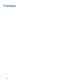
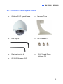
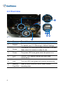
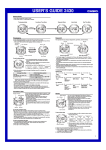
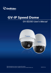
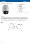
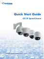
Quick Start Guide
GV-IP Speed Dome
Before attempting to connect or operate this product,
please read these instructions carefully and save this manual for future use.
ISD220200-QG-B
© 2013 GeoVision, Inc. All rights reserved.
Under the copyright laws, this manual may not be copied, in whole or in
part, without the written consent of GeoVision.
Every effort has been made to ensure that the information in this manual is
accurate. GeoVision, Inc. makes no expressed or implied warranty of any
kind and assumes no responsibility for errors or omissions. No liability is
assumed for incidental or consequential damages arising from the use of
the information or products contained herein. Features and specifications
are subject to change without notice.
GeoVision, Inc.
9F, No. 246, Sec. 1, Neihu Rd.,
Neihu District, Taipei, Taiwan
Tel: +886-2-8797-8377
Fax: +886-2-8797-8335
http://www.geovision.com.tw
Trademarks used in this manual: GeoVision, the GeoVision logo and GV
series products are trademarks of GeoVision, Inc. Windows and Windows
XP are registered trademarks of Microsoft Corporation.
June 2013
Contents
1. Introduction............................................................... 1
2. GV-SD220 / SD220-S................................................. 2
2.1 Packing List ........................................................................... 2
2.1.1 Indoor GV-IP Speed Dome........................................... 2
2.1.2 Outdoor GV-IP Speed Dome ........................................ 3
2.2 Overview................................................................................ 4
2.3 Installation.............................................................................. 5
2.3.1 Indoor GV-IP Speed Dome: Hard-Ceiling Mount........... 5
2.3.2 Outdoor GV-IP Speed Dome: Wall Mount..................... 7
2.4 Connecting the Cables........................................................... 9
2.5 Accessing the Camera ......................................................... 10
2.5.1 System Requirements ................................................ 10
2.5.2 Looking Up the IP Address and Logging In..................11
2.6 The Web Interface................................................................ 13
2.7 The PTZ Control Panel......................................................... 15
2.8 Configuring a Preset Position............................................... 17
2.9 Configuring a Sequence Route ............................................ 19
2.10 Configuring a Cruise .......................................................... 22
2.11 Configuring an Auto Pan..................................................... 23
2.12 Configuring a Tour.............................................................. 25
2.13 Upgrading System Firmware .............................................. 27
2.14 Restoring to Default Settings.............................................. 29
i
2.14.1 Restoring All the Settings.......................................... 29
2.14.2 Restoring System Settings Only ............................... 29
2.14.3 Restoring PTZ Configuration Settings Only............... 30
3. GV-SD200 / SD200-S............................................... 31
3.1 Packing List ......................................................................... 31
3.1.1 Indoor GV-IP Speed Dome......................................... 31
3.1.2 Outdoor GV-IP Speed Dome ...................................... 32
3.2 Overview.............................................................................. 33
3.3 Installation............................................................................ 34
3.3.1 Indoor Speed Dome Mount: Surface Mount ................ 34
3.3.2 Outdoor Speed Dome Mount: Mini Pendent Mount..... 37
3.4 Connecting the Cables......................................................... 39
3.5 Accessing the Camera ......................................................... 41
3.5.1 System Requirements ................................................ 41
3.5.2 Looking up the IP Address and Logging in.................. 42
3.6 The Web Interface................................................................ 44
3.7 The PTZ Control Panel......................................................... 45
3.8 Configuring a Preset Position............................................... 47
3.9 Configuring a Sequence Route ............................................ 49
3.10 Configuring a Cruise .......................................................... 52
3.11 Configuring an Auto Pan..................................................... 54
3.12 Configuring a Tour.............................................................. 56
ii
3.13 Upgrading System Firmware .............................................. 59
3.14 Restoring to Default Settings.............................................. 61
iii
iv
1. Introduction
Welcome to the GV-IP Speed Dome Quick Start Guide. In the following
sections, you will be guided through the basic installations and
configurations of the GV-SD220/GV-SD220-S/GV-SD200/GV-SD200-S.
For detailed information, see GV-IP Speed Dome User’s Manual on the
Software CD.
Model
Application
Description
GV-SD220
Indoor
GV-SD220-S
Outdoor
2 MP H.264, 20x optical zoom, 12x
digital zoom, WDR pro
GV-SD200
Indoor
GV-SD200-S
Outdoor
2 MP H.264, 18x optical zoom, 8x
digital zoom, WDR pro
2. GV-SD220 / SD220-S
2.1 Packing List
2.1.1 Indoor GV-IP Speed Dome
•
Indoor GV-IP Speed Dome
•
Hard-Ceiling Cover
•
Mounting Plate
•
GV-IP Speed Dome
Software CD
•
GV-NVR Software DVD
2
GV-SD220 / SD220-S
2.1.2 Outdoor GV-IP Speed Dome
•
Outdoor GV-IP Speed Dome
•
Pendant Tube
•
Hex Keys x 2
•
M6 Screws x 3
•
Desiccant pack x 4
•
GV-IP Speed Dome
Software CD
•
GV-NVR Software DVD
3
2.2 Overview
1
2 4
3 5
6
4
No.
Name
Description
1.
Default
Restores all the settings to the factory default values.
For details, see 2.13 Restoring to Default Settings.
2.
Status
The status LED turns green when the power is on and
fades when the camera is ready for use.
3.
Power
The power LED turns green when the power is on.
4.
ACT
The ACT LED flashes orange light upon data
transmission.
5.
Link
The Link LED turns green with Internet connectivity.
6.
Memory
Card Slot
Insert a micro SD/SDHC/SDXC card to store
recording data.
2
GV-SD220 / SD220-S
2.3 Installation
There are multiple ways to install the GV-IP Speed Dome. Only the
standard installation methods are introduced in the Quick Start Guide. For
details on optional installations, see Installing the GV-SD220/220-S IP
Speed Dome, Chapter 5, GV-Mount Installation Guide on the Software CD.
2.3.1 Indoor GV-IP Speed Dome: Hard-Ceiling Mount
Required Items
1.
•
Indoor packing (supplied)
•
ceiling screws x 3 (user-prepared)
Secure the mounting plate to the ceiling with self-prepared screws.
5
2.
3.
Secure the indoor GV-IP Speed Dome to the mounting plate.
A. Loosen the screw on the mounting plate
B.
Align the camera to the mounting plate and rotate the camera
body to the right.
C.
Tighten the screw.
Put on the hard-ceiling cover.
Note: Cut away a side of the cover if you want to run the cable through.
6
2
GV-SD220 / SD220-S
2.3.2 Outdoor GV-IP Speed Dome: Wall Mount
Required Items
1.
•
Outdoor packing (supplied)
•
ceiling screws x 4
(user-prepared)
Insert the desiccants to the camera.
Note: Be sure to conceal the desiccants in the GV-IP Speed Dome within
2 minutes of opening the desiccant pack.
A.
Remove the camera cover using the supplied hex key.
7
B.
Unpack two desiccants and insert them to the indicated places.
C.
Follow step 1A to secure the camera cover with the supplied
hex key.
2.
Thread the camera cable through the pendant tube and lock the
camera to the pendant tube.
3.
Secure the camera to the pendant tube with the supplied M6 screws.
4.
Secure the pendant tube to the wall with self-prepared screws.
8
2
GV-SD220 / SD220-S
2.4 Connecting the Cables
With the Data Cable, you can connect the power, microphone, speaker, and
I/O devices to the GV-IP Speed Dome. The Data Cable is illustrated as
below.
I/O Wires
Speaker
Microphone
Ethernet
No.
Wire
Definition
1
Orange
Alarm In 1
2
Yellow
Alarm In 2
3
Green
Alarm In 3
4
Blue
Alarm In 4
5
Pink
Ground
6
Purple
Alarm Out
7
White
Alarm Out Open
8
Gray
Alarm Out Close
Power Adapter
9
2.5 Accessing the Camera
2.5.1 System Requirements
To access GV-IP Speed Dome functions through Web browser, ensure your
PC is in good network connection and use one of the following web
browsers:
•
Microsoft Internet Explorer 7.x or later
•
Google Chrome
•
Mozilla Firefox
•
Safari
Note:
1.
For users of Internet Explorer 8, additional settings are required.
For details, see Appendix C. For more details, see 1.2 System
Requirements, GV-IP Speed Dome GV-SD220 User’s Manual on
the Software CD.
2.
With non-IE browsers,
10
A.
Motion Detection, Text Overlay, two-way audio and GPS
map settings are not supported.
B.
The Play function is only available on the live view window.
C.
RTSP streaming must be kept as enabled.
2
GV-SD220 / SD220-S
2.5.2 Looking Up the IP Address and Logging In
By default, the IP address of your GV-IP Speed Dome is assigned by the
DHCP server unless your router does not support DHCP. In this case, the
default IP address will be 192.168.0.10. Follow the steps below to look up
the dynamic IP address.
1.
Install the GV-IP Device Utility program from the Software CD.
Note: The PC installed with GV-IP Device Utility must be under the same
LAN with the camera you wish to configure.
2.
On the PC desktop, select Start, select Programs and select GV IP
Device Utility to execute the program. The GV IP Device Utility
window appears and automatically searches for the GV IP devices
on the same LAN.
3.
Click the Name or Mac Address column to sort.
4.
Find the Mac Address of the camera to see its IP address.
11
5.
To login, type the IP address in the browser. The login page appears.
6.
Type the default ID and password admin and click Apply to log in.
7.
When accessing the GV-IP Speed Dome for the first time, you must
set your browser to allow a one-time installation of GeoVision
ActiveX component onto your computer.
Note: If your router does not support DHCP, the default IP address will
be 192.168.0.10. In this case, it is strongly suggested to modify the IP
address to avoid IP address conflict with other GeoVision IP device on
the same LAN. For details, see Changing the IP Address in 2.1 Looking
Up the IP Address, GV-IP Speed Dome GV-SD220 User’s Manual on
the Software CD.
12
2
GV-SD220 / SD220-S
2.6 The Web Interface
12
11
10
1
No.
2
3
4
5
6
7
8
9
Name
Description
1
Play
Plays live video.
2
Stop
Stops playing video.
3
Microphone
Talks to the surveillance area from the local
computer.
4
Speaker
Listens to the audio around the camera.
13
No.
Name
Description
5
Snapshot
Takes a snapshot of live video.
6
File Save
Records live video to the local computer.
7
Full Screen
Switches to full screen view. Right-click the image
to have these options: Snapshot, Full Screen,
Resolution, Wide Angle Lens Dewarping, PIP,
PAP, GPS and Google Maps.
8
Visual PTZ
Clicks to switch to one of the three visual PTZ
control modes: Fixed Direction Move, Random
Move or Center Move.
9
PTZ Home
Click to return the dome view to the home position.
10
I/O Control
Starts the I/O Control Panel.
11
PTZ Control
Starts the PTZ Control Panel and the Visual PTZ.
12
Show
System
Menu
Brings up these functions: Alarm Notify, Video
and Audio Configuration, Remote Config, Show
Camera Name and Image Enhance.
For detail, see 3.1 The Live View Window, GV-IP Speed Dome GV-SD220
User’s Manual on the Software CD.
14
2
GV-SD220 / SD220-S
2.7 The PTZ Control Panel
Click the PTZ Control button on the Live View window and select PTZ
Control Panel. The PTZ Control Panel appears.
15
No.
Name
Description
1
Exit
Closes the PTZ control panel.
2
Pan / Tilt
Control
Moves the PTZ Camera to 8 directions: up, down,
left, right, left up, left down, right up and right
down.
3
Home
Brings the camera view back to the home point.
4
Zoom In /
Out
Shortens (zoom in) or lengthens (zoom out) the
apparent distance between the camera and the
view.
5
Focus In /
Out
Adjusts the sharpness of the camera view.
Brings up these functions:
6
Option
•
Dome movement settings (Preset,
Sequence, Auto Pan, Cruise and Tour)
•
Image settings
•
PTZ settings
•
System settings
For detail, see PTZ Control Panel, Chapter 4,
GV-IP Speed Dome GV-SD220 User’s Manual
on the Software CD.
7
16
Show Preset
Opens and closes the number pad.
2
GV-SD220 / SD220-S
2.8 Configuring a Preset Position
You can set up a preset position toward which the dome view moves. Up to
255 preset points can be configured and saved.
Setting Up a Preset
1.
Use the direction keys on the PTZ Control Panel to move the dome to
a desired position in Live View.
2.
Click Option on the PTZ Control Panel, click Preset Set, and select
the desired preset number to save the preset.
3.
To create another preset position, repeat Steps 1 and 2, and select a
different preset number to save.
17
Using a Preset
To move the dome view to a previously defined preset position, click Option
on the PTZ Control Panel, click Preset Go, and select a Preset number
which has been set up.
18
2
GV-SD220 / SD220-S
2.9 Configuring a Sequence Route
You can have the dome view move in a series of predefined movements.
Create a Sequence by linking a number of presets points. Up to 8
Sequences can be created and a minimum of 2 preset points must be
selected for a Sequence route to work.
Setting Up a Sequence
1.
From the PTZ control panel, click Option and select Setup. This dialog
box appears.
19
2.
Click Open and click Sequence located under PTZ Setting on the left
menu.
3.
Use the Index drop-down list to select the Sequence group number to
be configured. Up to 8 Indexes (Sequence groups) can be created.
4.
One Sequence group can include up to 16 Preset Points. Use the
Point drop-down list to select the number of Preset Points in this
Sequence group.
5.
Use the Preset drop-down list to select the Presets for this Sequence
group.
6.
Use the Dwell Time drop-down list to set the duration for the dome to
stay at this Preset. The duration time ranges from 1 to 255 seconds.
7.
Use the Speed drop-down list to set the speed at which the dome
travels from one Preset to another.
8.
To create another Sequence group, repeat Steps 1 to 6, and select a
different Index number.
9.
Click Save to complete the settings.
20
2
GV-SD220 / SD220-S
Starting and Stopping a Sequence
To start the dome view on a Sequence route, click Option on the PTZ
Control Panel, click Auto Go and select a Go Sequence number which has
been previously set. The dome view will continue moving once a Sequence
is started. To stop the movements, click any button on the PTZ Control
Panel.
21
2.10 Configuring a Cruise
You can set up a route consisting of different directions, angles, and zooms
for the GV-IP Speed Dome to follow. Up to 4 Cruises can be created.
Setting Up a Cruise
1.
Click Option on the PTZ Control Panel, click Auto Set and select Set
Cruise 1.
2.
Use Pan/Tilt Control keys and zoom in / out keys to set the desired
route path and zoom.
3.
When you are finished with setting up a Cruise 1 route, click Option,
click Auto and select Set Cruise Stop.
4.
To set up another Cruise route, repeat Steps 1 to 3, and select a
different Cruise number.
Starting and Stopping a Cruise
To start the GV-IP Speed Dome on a defined Cruise route, click Option on
the PTZ Control Panel, click Auto Go and select a Go Cruise number
which has been previously set. To stop a Cruise route in action, click any
button on the PTZ Control Panel.
22
2
GV-SD220 / SD220-S
2.11 Configuring an Auto Pan
The GV-IP Speed Dome can pan up to 360° endlessly to survey the
horizontal view between 2 pre-defined positions. You can configure up to 8
sets of Auto Pan routes.
Setting Up an Auto Pan
1.
Set up the vertical position of your GV-IP Speed Dome first. The
vertical direction set during or after the horizontal movement settings
will not be effective.
2.
Set up the start position of the Auto Pan.
3.
4.
A.
Use the control buttons on the PTZ control panel to move to a
desired start position.
B.
Click Option on the PTZ Control Panel, click Auto Set and
select Set Auto Pan 1 Start Position.
Set up the end position of the Auto Pan.
A.
Use the control buttons on the PTZ control panel to move to a
desired end position.
B.
Click Option, click Auto Set and select Set Auto Pan 1 Stop
Position.
To create another Auto Pan route, repeat Steps 1 to 4, and select a
different Auto Pan number.
For details on pan speed and the duration of dome view at the start/stop
positions, see 4.11 PTZ Settings-Other, GV-IP Speed Dome GV-SD220
User’s Manual on the Software CD.
Note: The zoom ratio of an Auto Pan’s Start Point will persist throughout
the whole path.
23
Starting and Stopping an Auto Pan
To start the GV-IP Speed Dome on an Auto Pan mode, click Option on the
PTZ Control Panel, click Auto and select an Auto Pan number which has
been previously set. To stop an Auto Pan, click any button on the PTZ
Control Panel.
24
2
GV-SD220 / SD220-S
2.12 Configuring a Tour
You can set up your GV-IP Speed Dome to move in a combination of preset
positions, Sequence, Cruise and Auto Pan. You can configure up to 8 Tour
routes.
Setting Up a Tour
1.
Follow the steps in Accessing the PTZ Configuration Dialog Box above
and click Open to display the PTZ Configuration dialog box, click
Tour located under PTZ Setting on the left menu.
2.
Use the Index drop-down list to select the Tour group number to be
configured. Up to 8 Indexes (Tour groups) can be created.
3.
One Tour group can include up to 16 sets of Preset Points, Sequence,
Cruise and Auto Pan. Use the Type drop-down list to select the
movement type.
25
4.
Use the Index drop-down list to select the movement number for each
movement type.
5.
To create another Tour group, repeat Steps 1 to 6, and select a
different Index number.
6.
Click Save to complete the settings.
Starting and Stopping a Tour
To start the GV-IP Speed Dome on a Tour route, click Option on the PTZ
Control Panel, click Auto Go and select a Go Tour number which has been
previously set. An enabled Tour will repeat until it is stopped by clicking any
button on the PTZ Control Panel.
26
2
GV-SD220 / SD220-S
2.13 Upgrading System Firmware
GeoVision periodically updates the latest firmware to the company website.
You can update your GV-IP Speed Dome firmware through the Web
interface or GV IP Device Utility included in the Software CD. For details on
firmware upgrade using GV IP Device Utility, see 7.1.2 Using the GV IP
Device Utility, GV-IP Speed Dome GV-SD220 User’s Manual on the
Software CD.
IMPORTANT:
1.
While the firmware is being updated,
A.
the power supply must not be interrupted, and
B.
do not unplug the Ethernet cable if the cable is the source of
power supply.
2.
Interruption of power supply during the upgrade causes not only
upgrade failure but also damages to the camera. In this case,
contact your sales representative and send your device back to
GeoVision for repair.
3.
Do not turn the power off 10 minutes after the firmware is updated.
4.
If firmware upgrade fails, you will need to restore the camera to
the factory default settings.
27
1.
In the Live View window, click the Show System Menu button and
select Remote Config. This dialog box appears.
2.
Click the Browser button to locate the firmware file (.img) saved at
your local computer.
3.
Click the Upgrade button to start upgrading.
28
2
GV-SD220 / SD220-S
2.14 Restoring to Default Settings
There are two parts to the GV-IP Speed Dome settings:
•
System settings: this refers to all the settings except the PTZ settings
•
PTZ configuration settings: this refers to settings in the PTZ
configuration dialog box
2.14.1 Restoring All the Settings
1.
Press and hold the Default button.
2.
When the status LED flashes twice, release the Default button. This
shall take about 6 seconds.
3.
The status LED fades when the default loading is completed.
2.14.2 Restoring System Settings Only
On the Web interface, select Tools and click the Load Default button. The
default loading will start shortly.
29
2.14.3 Restoring PTZ Configuration Settings Only
1.
Access the PTZ Configuration dialog box. For details, see Calling Up
the PTZ Control Panel and Accessing the PTZ settings, Chapter 4,
GV-IP Speed Dome GV-SD220 User’s Manual on the Software CD.
2.
On the PTZ Configuration dialog box, select System Configuration.
This dialog box appears.
3.
To restore default settings to all the settings in PTZ Configuration, click
Load Camera Default (Include PTZ). To restore default settings to
Image Settings and System Configuration settings only, click Load
Camera Default (Exclude PTZ).
30
3. GV-SD200 / SD200-S
3.1 Packing List
3.1.1 Indoor GV-IP Speed Dome
•
Indoor GV-IP Speed
Dome
•
•
Terminal Block
•
M3 Standard Screw (x1)
•
GV-IP Speed Dome
Software CD
•
M4 Screw (x5)
•
Plastic Anchor (x5)
•
GV-NVR Software DVD
Hard Ceiling Mount
(GV-MountD603)
3.1.2 Outdoor GV-IP Speed Dome
•
Outdoor GV-IP Speed Dome
•
M3 Standard Screw (x1)
•
M3 Security Screw (x1)
•
M5 Standard Screw (x1)
•
M5 Security Screw (x1)
•
Outdoor Mounting Kit
(GV-MountD902)
•
Waterproof Rubber
•
Mini Pendent Mount
•
Lubricant
•
GV-IP Speed Dome Software
CD
•
GV-NVR Software DVD
(GV-MountD202)
•
32
Security Torx
3
GV-SD200 / SD200-S
3.2 Overview
No.
Name
Description
A
LAN / High Power
PoE
Connects to a 10/100 Ethernet or High
Power PoE (for GV-SD200 only).
B
I/O Terminal Block
Connects to I/O devices. For details, see
3.4 Connecting the Cables in the Quick
Start Guide.
C
Power Port
Connects to power of AC 24V.
D
Memory Card Slot
Inserts a micro SD / SDHC card to store
recording data.
E
Reset Button
Resets to factory default. For details, see
3.13 Restoring to Default Settings in the
Quick Start Guide.
F
Two Way Audio
Connects audio input and output. For
details, see 3.4 Connect the Cables in the
Quick Start Guide.
33
3.3 Installation
There are several mounting methods for GV-IP Speed Dome. In this Quick
Start Guide, we only show you the standard mounting methods with the
standard packing. For other mounting methods, refer to GV-IP Speed Dome
GV-SD200 User’s Manual.
3.3.1 Indoor Speed Dome Mount: Surface Mount
GV-MountD603
(Supplied)
1.
Mark the positions of the three screw holes on the Hard Ceiling
Mount at the chosen installation location.
2.
In the marked locations, drill each hole slightly smaller than the
supplied Screw Anchors, and put supplied Anchors into these drilled
holes.
34
3
GV-SD200 / SD200-S
3.
Fasten the Hard Ceiling Mount with the three supplied M4
Self-tapping Screws.
4.
Thread the connected cables and wires through the center hole of
the Mount and connect the cable to the camera body.
5.
Users can choose to hide the cables and wires inside the ceiling, and
put the rubber from the accessory package to fill the gap at the side
of the Fixing Plate. Or let the cables out from the gap on the side of
the Fixing Plate (as shown in the diagram).
6.
Install the Camera on the fixed Hard Ceiling Mount by turning the
Camera clockwise.
35
7.
Fasten the screw at the side of the Fixing Plate.
8.
After installing the Camera on the Hard Ceiling Mount, put the Dome
Cover back, and use a flat screw drive to fasten two supplied Flat
Screws on the Dome Cover.
9.
Fasten the supplied Standard Screw on the Dome Cover.
36
3
GV-SD200 / SD200-S
3.3.2 Outdoor Speed Dome Mount: Mini Pendent Mount
Required items:
1.
•
Outdoor
packing
(supplied)
•
Wall screws x 4
(user-prepared)
Make a cable entry hole on the wall to recess the cables. You can
also push up the Cable Entry Board on the Mini Pendent Mount’s
Mounting Plate to place the cables, as shown in the photo below.
Mounting Plate
Cable Entry Board
2.
Fix the Mini Pendent Mount on the wall with suitable screws and
screw anchors of your choice.
37
3.
Attach the Waterproof Rubber to the Mini Pendent Mount.
4.
Run the cable(s) through the Mini Pendent Mount.
Note: Block the cable entry hole with the supplied sponge to avoid
insects entering the Pendent Mount. The sponge can be placed in two
ways as shown in the illustrations below.
Sponge
Sponge
5.
Thread the cable(s) through the Mounting Kit and join the Mounting
Kit to the Mini Pendent Mount with the supplied screws and washers.
Then adjust the Waterproof Rubber to the joint.
6.
Connect the cable(s) to the Dome Camera.
7.
Join the Dome Camera to the Mounting Kit with the supplied screw
and washers.
38
3
GV-SD200 / SD200-S
3.4 Connecting the Cables
Connect your IP Speed Dome to power, network and other cables.
Connecting Power
Pin
Definition
1
AC 24_1
2
GND
3
AC 24_2
Note: If you are using GeoVision’s optional power adaptors, connect the
green or green/yellow wire to GND. The two remaining wires are
interchangeable, and both wires can be connected to AC_2 or AC_1.
Connecting Ethernet Cable
The High Power PoE function is only supported for
GV-SD200.
39
Connecting Alarm I/O
Pin
Definition
Pin
1
Alarm_Out_NC_1
7
Alarm_Out_COM_2
2
Alarm_Out_NO_1
8
GND
3
Alarm_Out_COM_1
9
Alarm_In_4
4
GND
10
Alarm_In_3
5
Alarm_Out_NC_2
11
Alarm_In_2
6
Alarm_Out_NO_2
12
Alarm_In_1
Connecting Audio
40
Definition
Pin
Definition
1
Line_Out
2
GND
3
Line_In
3
GV-SD200 / SD200-S
3.5 Accessing the Camera
3.5.1 System Requirements
To perform the GV-IP Speed Dome via web browser, ensure your PC is in
good network connection, and use one of the following web browsers.
•
Internet Explorer 7.0 or later
•
Firefox
•
Google Chrome
•
Safari
Note: With non-IE browsers, only the Play function is available on the
live view window.
41
3.5.2 Looking up the IP Address and Logging in
By default, the IP address of your GV-IP Speed Dome is assigned by the
DHCP server unless your router does not support DHCP. In this case, the
default IP address will be 192.168.0.10. Follow the steps below to look up
the dynamic IP address.
1.
Install the GV-IP Device Utility program from the Software CD.
Note: The PC installed with GV-IP Device Utility must be under the same
LAN with the camera you wish to configure.
2.
button to search for the
On the GV-IP Utility window, click the
GV-IP Speed Dome. Click the Name or Mac Address column to
sort.
3.
Find the camera with its Mac Address to see the IP address.
42
3
GV-SD200 / SD200-S
4.
To login, type the IP address in your web browser. A dialog box
appears.
5.
Type the default username and password admin.
6.
Click OK to access the Web interface.
7.
When accessing the GV-IP Speed Dome for the first time, you must
set your browser to allow a one-time installation of DC Viewer onto
your computer.
Note: If your router does not support DHCP, the default IP address will
be 192.168.0.10. In this case, it is strongly suggested to modify the IP
address to avoid IP address conflict with other GeoVision IP device on
the same LAN. For details, see 3.1.2 Changing the IP Address, GV-IP
Speed Dome GV-SD200 User’s Manual on the Software CD.
43
3.6 The Web Interface
After logging onto the GV-IP Speed Dome, users will see the Home page as
shown below:
Main Tabs
Focus Mode
Language Selection
Time Display
Select Video
Format
Display Mode
Codec Info
PTZ Control Panel
Web Recording
Pause Video Streaming
Snapshot
Speaker
Talk
Note: Refer to Administrator Mode, Chapter 4, GV-IP Speed Dome
GV-SD200 User’s Manual on the Software CD for details.
44
3
GV-SD200 / SD200-S
3.7 The PTZ Control Panel
Click the
Button
button on the home page. The PTZ Control Panel appears.
Description
Moves the camera to 8 directions.
Zooms in. Shortens the apparent distance between the
camera and the view.
Zooms out. Lengthens the apparent distance between
the camera and the view.
45
Button
Description
Focuses in. Changes the sharpness of the view.
Focuses out. Changes the sharpness of the view.
Automatically adjusts the focus.
Enlarges the aperture opening.
Automatically adjusts the aperture opening.
Reduces the aperture opening.
Moves to a defined Preset point.
Preset
Starts a defined Cruise path.
Cruise
Starts a defined Sequence route.
Sequence
Adjusts the pan/tilt speed.
PT Speed
46
3
GV-SD200 / SD200-S
3.8 Configuring a Preset Position
You can set up a preset position toward which the dome view moves. Up to
256 preset points can be configured and saved.
Setting up a Preset
1.
Click the PTZ tab and select Preset from the left menu of the Web
interface.
2.
Click the dome view and drag the cursor to a desired position.
3.
Use the Zoom and Focus buttons to adjust the dome view.
4.
Use the Num drop-down list to select a number to define a Preset point.
Click Pre page or Next Page button to select numbers from 1 to 256.
5.
Type a name to describe the selected number in the Name field.
6.
To create another Preset point, repeat Steps 2 to 5 and select a
different preset number.
7.
Click Set to save the settings.
8.
Use the Preset Go drop-down list to select a Preset point to test your
settings.
47
Using a Preset
To move the dome view to a previously defined Preset point, click the Home
tab and click on the PTZ Control Panel button
. Select the defined
number from the Preset drop-down list and click the
button.
48
3
GV-SD200 / SD200-S
3.9 Configuring a Sequence Route
You can have the dome view move in a series of predefined movements.
Create a Sequence by linking a number of presets points. Up to 8
Sequences can be created and a minimum of 2 Preset Points must be
selected for a Sequence line to work.
Setting up a Sequence
1.
Click the PTZ tab and select Sequence from the left menu of the Web
interface.
49
2.
Click the Edit button under Sequence Setting.
3.
Use the Sequence Line drop-down list to select a Sequence route
number to be configured.
4.
Use the Name drop-down list to select the desired Preset points for the
Sequence route.
5.
One Sequence line include up to 64 Preset points. Use the Pre Page
and Next Page buttons to reach numbers1 to 64.
6.
Type a number in the Dwell Time field to set the duration for the dome
to stay at this Preset. The duration time ranges from 0 to 127 seconds.
7.
Type a number in the Speed field to set the speed level at which the
dome travels from one Preset to another. The speed level ranges from
0 to 14.
8.
Click Save to complete the settings.
9.
To create another Sequence, repeat Steps 3 to 8 and select a different
Sequence line number.
50
3
GV-SD200 / SD200-S
10. Return to the Sequence page. Use the Sequence Line drop-down list
to select a Sequence route number and click Go to test your settings.
Starting and Stopping a Sequence
To start the dome view on a Sequence route, click the Home tab, click the
PTZ Control Panel button
and select a Sequence number which
has been previously set. The dome view will continue moving once a
Sequence is started. To stop the movements, click any button on the PTZ
Control Panel.
51
3.10 Configuring a Cruise
You can set up a path consisting of different directions, angles, and zooms
for the GV-IP Speed Dome to follow. Up to 8 Cruises can be created.
Setting up a Cruise
1.
Click the PTZ tab and select Cruise from the left menu of the Web
interface.
2.
Use the Cruise Path drop-down list to select a Cruise path number to
be configured.
3.
Click the dome view and drag the cursor to a desired position as the
Start Point of a Cruise path.
4.
Click the Set button of Record Start and start programming the Cruise
path by dragging the red cursor on the dome view.
5.
Use the Zoom and Focus buttons to adjust the dome view.
6.
Click the Set button of Record End to quit.
7.
To create another Cruise, repeat Steps 2 to 6 and select a different
Cruise path number.
52
3
8.
GV-SD200 / SD200-S
Use the Cruise Path drop-down list to select a Cruise path number
and click the Run button to test your settings.
Starting and Stopping a Cruise
To start the dome view on a Cruise path, click the Home tab, click the PTZ
Control Panel button
and select a Cruise number which has been
previously set. The dome view will continue moving once a Cruise is started.
To stop the movements, click any buttons on the PTZ Control Panel.
53
3.11 Configuring an Auto Pan
The GV-IP Speed Dome can pan up to 360° endlessly to survey the
horizontal view between 2 pre-defined positions. You can configure up to 4
sets of Auto Pan paths.
Setting up a Auto Pan
1.
Click the PTZ tab and select Auto Pan from the left menu of the Web
interface.
2.
Use the Auto Pan Path drop-down list to select an Auto Pan path
number to be configured.
3.
Use the Speed drop-down list to set the speed level from 0 to 3 at
which the dome travels from the Start Point to the End Point.
4.
Click the dome view and drag the cursor to a desired position. Click the
Set button of Start Point to save the setting.
5.
Click the dome view and drag the cursor to a desired position. Click the
Set button of End Point to complete the setting.
6.
To create another Auto Pan path, repeat Steps 2 to 5 and select a
different path number.
54
3
GV-SD200 / SD200-S
Note: The zoom ratio of an Auto Pan’s Start Point will persist throughout
the whole path.
Starting and Stopping a Auto Pan
To start the dome view on an Auto Pan path, click the Run button on the
Auto Pan page. The dome view will continue moving once an Auto Pan is
started. To stop the movements, move the cursor on the dome view and
drag it to any directions.
55
3.12 Configuring a Tour
You can set up your GV-IP Speed Dome to move in a combination of Preset,
Sequence, Cruise and Auto Pan. You can configure up to 16 Tour routes.
Setting up a Tour
1.
56
Click the PTZ tab and select Tour Function from the left menu of the
Web interface.
3
GV-SD200 / SD200-S
2.
Click the Edit button under Tour Function Setting.
3.
Use the Tour Function drop-down list to select a number to be
configured.
4.
Use the Function drop-down list to select a Preset, Sequence,
Cruise or Auto Pan.
5.
Type a number in the No. field to specify the Preset, Sequence,
Cruise, and Auto Pan.
6.
Click the Save button to complete the setting.
7.
To create another Tour route, repeat Steps 3 to 6 and select a
different Tour Function number.
8.
Return to the Tour Function page. Use the Tour Function Line
drop-down list to select a Tour route number and click Go to test your
settings.
57
Starting and Stopping a Tour
To start the dome view on a Tour path, click the Run button on the Tour
Function page. The dome view will continue moving once a Tour is started.
To stop the movements, move the cursor on the dome view and drag it to
any directions.
58
3
GV-SD200 / SD200-S
3.13 Upgrading System Firmware
GeoVision periodically releases the updated firmware on the website.
Update your camera to the latest firmware through its Web interface.
IMPORTANT:
1.
Stop monitoring of the camera.
2.
Stop the connection to GV-System.
3.
While the firmware is being updated,
A.
the power supply must not be interrupted, and
B.
do not unplug the Ethernet cable if the cable is the source of
power supply (Power over Ethernet or PoE supported).
4.
The interruption of power supply during updating causes not only
update failures but also damages to your camera. In this case,
please contact your sales representative and send your device back
to GeoVision for repair.
5.
Do not turn the power off for 10 minutes after the firmware is
updated.
59
1.
Click the System tab and select Software Upgrade from the left
menu.
2.
Click the Browse button and select one firmware file to be uploaded.
Note: Do not change the upgrade file name, or the system will fail to find
the file.
3.
Use the drop-down list to select the corresponding type of file you want
to upgrade. For example, if the file you uploaded is
GV-SD200_switch_V103_130115, select SD200_switch from the
drop-down list.
4.
Click the Upgrade button.
5.
Repeat the above steps for all remaining firmware files. All four
firmware files must be upgraded for the camera to function properly.
60
3
GV-SD200 / SD200-S
3.14 Restoring to Default Settings
You can restore the camera to factory default settings using the Web
interface or directly on the camera. On the Web interface, you can choose
to do a full restoration or partial restoration of default settings.
Using the Web Interface
1.
Click the System tab and select Factory Default from the left menu.
2.
To restore all settings to factory default, click the Full Restore button.
The system will restart in 30 seconds. Note that the IP address will be
restored to default.
3.
To restore all settings to factory default except for the network and the
PTZ settings, click the Partial Restore button. The system will restart
in 30 seconds.
61
Directly on the Camera
To restore to default settings directly on the camera, use a pointy object,
such as the tip of a pen to hold down the Load default button (Button E
below) for about 30 seconds while the power is on. The lens will rotate
briefly when load default is completed.
62