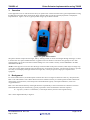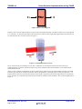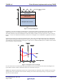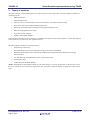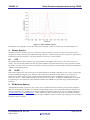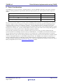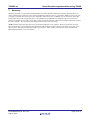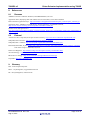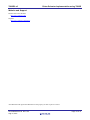
1
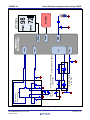
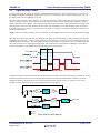
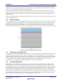
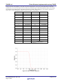
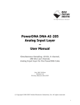
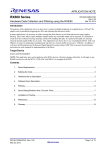
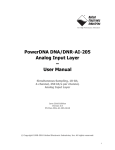
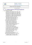
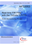
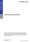
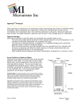
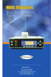
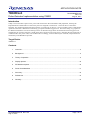
APPLICATION NOTE 78K0R/Lx3 Pulse-Oximeter Implementation using 78K0R R01AN0609EU0100 Rev.1.00 Aug 16, 2011 Introduction Today’s microcontrollers require lower power and contain more advanced features and peripherals, allowing the implementation of medical devices that in the past were relegated to Clinical use. One such device is the PulseOximeter. By combining LEDs with optical sensors in a small clip on devices, it is now possible to have a small battery operated version that is beneficial in monitoring your pulse and blood oxygen level. This is becoming very popular in the Wellness and Fitness area for use during exercise to maintain a target heart rate and monitor blood oxygen levels. The data may be critical if someone is under direct doctor supervision for such activity, and when the microcontroller is combined with a low power radio, such as Bluetooth Low-Energy, real-time data may be collected, analyzed and even sent directly to the Healthcare provider. Target Device 78K0R/Lx3 Contents 1. Overview ........................................................................................................................................... 2 2. Background ....................................................................................................................................... 2 3. Theory of operation ........................................................................................................................... 5 4. Display Options ............................................................................................................................... 10 5. RF Modules Options........................................................................................................................ 10 6. Power Considerations ..................................................................................................................... 11 7. Summary ......................................................................................................................................... 12 8. References ...................................................................................................................................... 13 9. Glossary .......................................................................................................................................... 13 R01AN0609EU0100 Rev.1.00 Aug 16, 2011 Page 1 of 14 78K0R/Lx3 1. Pulse-Oximeter Implementation using 78K0R Overview In this application note we will discuss the theory of operation for a Pulse-Oximeter and a typical implementation using the K0R microcontroller family and specific family members that provide the requisite peripherals to simplify the implementation. Figure 1 shows a typical portable” finger clip-on Pulse Oximeter. Figure 1: Typical Pulse-Oximeter The pulse-oximeter clamps onto the finger, and by “shining” LEDs of various wavelengths through the finger, it is able to monitor the users pulse and determine the oxygenation level of the blood. The units can typically be set to take measurements at given intervals and record the readings into “non-volatile” memory such as EEPROM or FLASH embedded in the MCU. NOTE: In this app note we will not show the larger Clinical models of the pulse-oximeter (which may have finger clip or ear clip), but the reader should be aware the basic theory of operation is the same. The unit may be larger to provide more easy to read display and larger batteries for longer life, or it may be part of a larger piece of patient care equipment. 2. Background For such a modern device, the modern pulse-oximeter show above in Figure 1is based on some very old optical laws, Beer’s Law and Lambert’s Law. When discussed in terms of Pulse-oximetry it is listed together as Beer-Lambert law which refers, in simple terms, to the absorption of monochromatic light by a transparent substance, in this case oxygenated blood. Beer’s law states that the intensity of the light decreases exponentially as the concentration of a substance increases. Stated mathematically the transmissivity typically expressed in terms of absorbance which for liquids is: A = -log10(I/IO), where A is absorbance, I is the output intensity and IO is the original intensity. This is show diagrammatically in Figure 2. R01AN0609EU0100 Rev.1.00 Aug 16, 2011 Page 2 of 14 78K0R/Lx3 Pulse-Oximeter Implementation using 78K0R IO I Figure 2: Beer's Law Diagram Lambert’s law states that that absorption is proportional to the light path length. The Beer-Lambert Law can be applied to co-oximeters. An arterial blood sample can be placed in a container where light path length and the concentration can be controlled such as a curvette as shown in Figure 3. Figure 3: Arterial Blood in a Curvette So for Arterial blood (non-pulsatile) in a lab, this is simple due to controlled environment, but becomes more complicated when we want to measure blood in a non-invasive manner where tissue thickness varies and the blood pulses through arteries. Today’s pulse-oximeters are decadents of a device developed by Takuo Aoyagi at Nihon Kohden, who discovered that arterial oxygen saturation could be measured by looking for pulsations in the light signals coming through tissue. It is based on the fact that if we measure the absorption rate, the DC component represents the light absorb by non-pulsatile tissue, while the AC component represents the non-constant or pulsation of the blood flow. This is shown graphically in Figure 4. R01AN0609EU0100 Rev.1.00 Aug 16, 2011 Page 3 of 14 78K0R/Lx3 Pulse-Oximeter Implementation using 78K0R Absorption due to pulsatile Blood Absorption due to non-pulsatile arterial blood Absorption due to Venous and capillary Blood Absorption due to Tissue Time Figure 4: Absorption Diagram In addition, it was discovered that oxygenated blood, oxyhemoglobin and deoxygenated blood, deoxyhemoglobin, have different absorption levels at differing wavelengths, oxyhemoglobin (HbO2) and deoxyhemoglobin (Hb) being maximally absorbent in the infrared band (850 to 1000 nm) and the red (600 to 750 nm) respectively. This is shown in Figure 5. So if we can measure the absorbency at these two wavelengths we can estimate the oxygenation level of the blood. One final point in this is the concept of the Isobestic Point. This is the wavelength of light where the oxyhemoglobin (HbO2) and deoxyhemoglobin (Hb) absorption is equal as shown in Figure 5. Most of the modern pulse-oximeters do not include this in their measurements, limiting their “light sources” to Red and Infrared, but it could be used as another point of reference in the measurement. Isobestic Point (Red) 660nm 10 (Infrared) 910nm Hbo2 Hb Wavelength (nm) 0.1 600 700 900 1000 Figure 5: Absorption versus wavelength So now we know how to measure pulse and oxygen saturation level, we need to look at the basic block diagram of a typical Pulse-oximeter in order to determine the best microcontroller for the job. NOTE: This method for determining oxygen levels in the blood does have limitations. Pulse-oximeters may give false reading under certain conditions such as someone suffering from Carbon monoxide poisoning or respiratory acidosis due to excess carbon dioxide. R01AN0609EU0100 Rev.1.00 Aug 16, 2011 Page 4 of 14 78K0R/Lx3 3. Pulse-Oximeter Implementation using 78K0R Theory of operation The pulse-oximeter is actually doing quite a bit of processing for such a simple task. The main hardware elements of our design will be: RED Light Source Infrared Light Source Intensity control to accommodate various tissues thickness, and adjust for ambient light. Photo-sensor that work in RED and Infrared Spectrum Gain stage (with offset adjust) to amplify small signal from Photo-sensor ADC for sampling Photo-sensor data LCD control to drive display UART to talk to Radio Module These hardware elements are shown in Figure 6, including some details on the Analog condition / control (this diagram will be referred to several time in this Application note). The main Software elements of our design will be: LED Intensity control loop DC Offset Elimination to get the Pulsitile Absorption rates (Infrared and Red) Measuring the absorption rate of the Infrared and Red light through the blood to determine the Oxygen Saturation level. Low Pass filtering of sampled Photo-sensor signal to detect pulse LCD Display driver UART driver for the Radio Module NOTE: Although the LCD and Radio module are part of this design, we will not discuss them in detail as they are not the “core” material to be covered in this Application note. There are a sufficient number of Application notes on these topics. R01AN0609EU0100 Rev.1.00 Aug 16, 2011 Page 5 of 14 R1 R3 R01AN0609EU0100 Rev.1.00 Aug 16, 2011 D2 D1 VCC GND GND R12 R11 VCC PIN Diode D3 Sensor Assembly INFRARED LED RED LED GND R5 Q4 Q2 LED Drive with Current control R4 R2 GND C3 R9 U1 1 z R13 Op-amps internal to the MCU 3 R7 C1 3 R8 C2 U2 1 GND C4 R10 Current to Voltage Gain stage with Offset Converter GND R6 Q3 Q1 GND D4 Zener Schottky D5 GND 78K0R/Lx3 Pulse-Oximeter Implementation using 78K0R Figure 6: Pulse-Oximeter Block Diagram using 78K0R/Lx3 Page 6 of 14 78K0R/Lx3 3.1 Pulse-Oximeter Implementation using 78K0R Light Intensity Control Lets first look at how we control the intensity of the RED and infrared LEDs. If you examine Figure 6, you will see that the RED and Infrared LEDs are wired in opposite directions so that they both cannot be on at the same time. Q1 through Q4 form a sort of H-Bridge if you will. The DAC sets the bias the both Q3 and Q4. As we increase the output voltage on the DAC the base current increases and as a result the collector current increases. This will control the amount of current flowing through the respective diodes connected to their collector. The control system will set the initial value to get a good mid-scale reading on the photo diode to account for tissue thickness on the current user (large fingers versus delicate fingers and varying skin thickness from person to person). It can then track very slowly in response to changing ambient light conditions and movement of the finger. NOTE: The low pass filter formed by R9 / C3 is optional. It is intended to remove any “noise” from the DAC changes. The GPIO controls the upper half and will alternately turn on Q1 and Q2 alternately providing voltage to the Infrared and RED LED respectively. Relative timing operation is show in Figure 7. One point to note is that the RED and the Infrared are driven alternately. This will typically be done at some higher rate and the user may even want to sync the drive with the ADC the is sampling the Photo-diode. This lends itself to Complementary PWM drive, so this drive could be automated by using PWM timer outputs instead of just GPIO toggling. Figure 7: LED Drive Signal Timing The Photo-receptor is a PIN diode operated in the Photoconductive mode. The input of the op-amp is biased by the R12 and R13 to produce the reverse bias on the PIN photo Diode D3. This bias should be chosen such that you do not damage the diode by exceeding the reverse rating, but high enough to get the response you desire in your system. The basic control LED control loop is shown diagrammatically in Figure 8. Figure 8: Basic Control Diagram R01AN0609EU0100 Rev.1.00 Aug 16, 2011 Page 7 of 14 78K0R/Lx3 Pulse-Oximeter Implementation using 78K0R U1 and R7 create a current to voltage converter, which converts the current in D3 to voltage, which varies as the light striking it varies. The signal out of this op-amp is still very small. U2, R8 and R13 form a gain stage to amplify this signal so it will be of sufficient strength to be read by the ADC. If we run a filtering and control loop on the incoming pulse signal, we can detect the DC component. This value is related to the DC component of the signal as shown in Figure 4. Using this value we can control the DAC output and thus the offset into the amplifier, thereby eliminating the DC component leaving only the pulsitile component in the output of the ADC. NOTE: Individual algorithms and implementation may differ (i.e. the IP of the oximeter designer), this Application note shows one possible version. 3.2 Pulse Counting So the typical heart rate of the average human being will be about 70 beats per minute. The data coming from the ADC will contain data, typically higher frequency data that is not part of the pulse. This data may be switching noise from that LED control, sampling rate anomalies, etc. If we take the pulsitile data that is coming from the ADC and run it through a low pass filter, typically a FIR filter, we will be left with just the heart rate, which will be low enough to count. Typical data taken from a 10 bit ADC is shown in Figure 9, which is taken from the Pulse-Oximeter experiments. Figure 9: 10 Bit ADC data and post filter data 3.3 Absorption Level Detection So assuming we drive the RED and Infrared LED to achieve a similar light output (not the measured level at the ADC), and the PIN diode is selected such that it is similar in sensitivity to the two wavelengths, then we have the means to differentiate between absorbency levels for the two wavelengths. So as we alternate between the RED and the Infrared Drive, the absolute value of the ADC output represents the absorbency level of the pulsitile blood. If we refer back to the using the delta of the absorption readings at 660nm (RED) and at 910 nm (Infrared) we can calculate the Oxygenation levels of the blood (oxyhemoglobin (HbO2) versus deoxyhemoglobin (Hb)). 3.4 Data Sampling Rates Although this is not an application note on Filtering concepts, it would not be complete without some discussion of filtering sample rates. Since the control algorithm is removing the DC component, all we need is a simple low pass filter, and a FIR is what is recommended. Since the human heartbeat is typically 70 bpm or about 1+ Hz, you can see that we can basically chose the oversampling rate that we need to meet the requirements of a filter to detect the pulse. If you happened to count the samples in Figure 9, you will see approximately 30 samples per beat, so a sample rate of 30Hz , or about 3x oversampling if we set our passband to 9Hz. This 9 Hz point works our even if we consider the heart rate while exercising at say 150 bpm or about 2.5Hz. This can be done with a simple FIR filter and is well within the performance of the 78K0R/Lx3 processor. In fact the MCU clock may be chosen to save power while still being able to run the filter. Let’s take a quick look at the implementation of such a filter. R01AN0609EU0100 Rev.1.00 Aug 16, 2011 Page 8 of 14 78K0R/Lx3 Pulse-Oximeter Implementation using 78K0R Using a tool such as ScopeFIR, we can plug in our filter requirements. So per our previous discussion on the filter requirements, we will set the sample rate, fs, at 30Hz, our passband upper at 9Hz and stopband at 12Hz. In this design we will limit the passband ripple to 1db and the attenuation to 40db. These parameters will yield the coefficients in Table 1below. The resulting filter response is shown in Figure 10 and Figure 11 . TAP Coeffs TAP Coeffs 1 0.00036195 17 0.26060402 2 ‐0.00352014 18 ‐0.14329290 3 0.00061206 19 0.02206012 4 0.00473972 20 0.04708661 5 ‐0.00886259 21 ‐0.05069955 6 0.00411291 22 0.01672780 7 0.01024165 23 0.01489951 8 ‐0.02236460 24 ‐0.02236460 9 0.01489951 25 0.01024165 10 0.01672780 26 0.00411291 11 ‐0.05069955 27 ‐0.00886259 12 0.04708661 28 0.00473972 13 0.02206012 29 0.00061206 14 ‐0.14329290 30 ‐0.00352014 15 0.26060402 31 0.00036195 16 0.69079636 Table 1: Low-pass Filter Coefficients Figure 10: Filter Frequency Response R01AN0609EU0100 Rev.1.00 Aug 16, 2011 Page 9 of 14 78K0R/Lx3 Pulse-Oximeter Implementation using 78K0R Figure 11: Filter Impulse response The designer is encouraged to review basic filter theory and “play” with some of these low-cost filter design tools. 4. Display Options The Pulse oximeter is normally used in a “continuous” monitoring mode. The user will put it on and monitor their Oxygen level (while exercising, for health monitoring, whatever). Therefore display power is important. Some unit are LED based (as the unit in Figure 1), but more and more are moving to LCD or OLED. 4.1 LCD The 78K0R/Lx3 has a built in segment type LCD peripheral. It is capable of driving up to 160 “pixels” (40 seg x 4 comm). This is more than sufficient to drive the required number of segments and icons for the typical pulse-oximeter. The LCD is a “power conscious” choice for a display in a battery power unit. Note the LCD does require a backlight for visibility in low-light situations. 4.2 OLED Some of the “higher-end” units are moving to an OLED display for the features that they provide - better viewing angle, no need to backlight, and good power efficiency. The downside is that OLED usually requires “drive electronics” similar to TFT LCDs. There are many OLED module available from various manufacturers that have the “drive electronics” built-in. These modules typically only require a serial interface. So adding an OLED display is as simple as connecting it to one of the many serial interface available in the 78K0R/Lx3 (typically using an SPI/synchronous interface). 5. RF Modules Options Although the RF module is left to the user’s choice, some consideration must be made for power and interoperability. There are many radio options, but if you consider interoperability and low power combined with the fact that these are basically medical devices, including use in Wellness and Fitness Domains, there seems to be two leading technologies, ANT (including ANT+) and Bluetooth LE. Since modules with their accompanying “Stacks” are available for these protocols and they communicate with the MCU through a standard serial port we will not go too deeply into this subject. Research is left to the reader. R01AN0609EU0100 Rev.1.00 Aug 16, 2011 Page 10 of 14 78K0R/Lx3 6. Pulse-Oximeter Implementation using 78K0R Power Considerations The 78K0R/Lx3 is a low power device. Operating down to 1.8V, the 78K0R/Lx3 has many “low-power” operating modes for meeting performance requirements while achieving long battery life. Some typical currents are given in Table 2. MODE Typical Current Operating Mode, fIH = 1 MHz, VDD=3.0V 190 μA Operating Mode, fSUB = 32.768 kHz, VDD=3.0V 3.9 μA RTC Operating Current, fSUB = 32.768 kHz, VDD=3.0V 0.2 μA Table 2: Sample operating Current So you can see from the numbers, it can easily run for extended periods on batteries. A typical battery powered Pulse– Oximeter is made to run for a long time on a single set of batteries, with much of the time just maintaining the RTC with brief periods (1-2 hours) of “continuous” operation. A typical design may have it powered by 2 AAA cells (1200mAh for Alkaline). Now we are not doing a full power analysis, but it is easy to see, the microcontroller is not the limiting factor in battery life. Typically the RF module will draw a larger share of the current if doing data aggregation and monitoring by a hosting device such as a Bluetooth equipped Cell phone. So for this basic Application note, all that is needed to connect power to the device is a battery holder and some protection diodes to avoid damage in from incorrectly installed batteries. The 78K0R/Lx3 has both an internal Poweron Clear function and Low-Voltage detector function, so no external reset or voltage monitoring device is required. NOTE: With all the “green” devices emerging from the design world, the power section would not be complete without a word on rechargeable batteries (to reduce battery disposal waste). The 78K0R/Lx3 has sufficient “horsepower” to manage rechargeable batteries provided the necessary additional battery management and safety circuits are added (current monitoring, thermal and overcharge protection, etc.). The user is directed to the references section for a link to Battery management devices on the Renesas Power Management website. R01AN0609EU0100 Rev.1.00 Aug 16, 2011 Page 11 of 14 78K0R/Lx3 7. Pulse-Oximeter Implementation using 78K0R Summary The Pulse-Oximeter is a great tool for both Healthcare as well as Wellness and Fitness training. With the advent of microcontrollers that require less power (while maintaining compute power), it is possible to build low chip count, lowcost battery operated devices that were once relegated to Clinical use only. In addition, we can utilize low-power RF technologies that provide features that allow it to communicate with Health Care “Manager” Devices such as Cell phones. Our health care providers can get better, more accurate and “fresher” data from our monitoring devices such as the pulse-oximeter. We can monitor our status real-time while we are exercising. NOTE: Renesas Electronics has many Low-power Microcontrollers in its portfolio. We have just shown one such Microcontroller that can be applied to this application with the features shown. Based on the features you want your device to have, there may be one better suited to your design. Please contact you local sales rep or distributor for additional information or visit our Website. R01AN0609EU0100 Rev.1.00 Aug 16, 2011 Page 12 of 14 78K0R/Lx3 8. 8.1 Pulse-Oximeter Implementation using 78K0R References Renesas 78K0R/Lx3-M User’s Manual: Hardware, R01UH0004EJ0401, Rev 4.01 Application Note, Displaying Data with 78K0/Lx2 LCD Controllers, U18273EU1V0AN00 Pulse-Oximeter Application Flyer. http://am.renesas.com/applications/healthcare/pulse_oximeter/pulse_oximeter.jsp Application Note, 78K0R/Lx3 FLASH Memory Self Programming, U19484EE2V0AN00, http://www2.renesas.com/maps_download/pdf/U19484EE2V0AN00.pdf Renesas Power management ICs: http://am.renesas.com/products/standard_ic/general_purpose_linear/power_management_linear/power_management_lin ear_landing.jsp 8.2 External Anaesthesia UK 11 Sept 2004, Principles of Pulse-oximetry, http://www.frca.co.uk/article.aspx?articleid=332 Wikipedia, Pulse-Oximeter: http://en.wikipedia.org/wiki/Pulse_oximeter Wikipedia, Beer’s-Lambert: http://en.wikipedia.org/wiki/Beer%E2%80%93Lambert_law Brand TM, Brand ME, Jay GD. Enamel nail polish does not interfere with pulse oximetry among normoxic volunteers J Clin Monit Comput. 2002 Feb;17(2):93-6. Home Care Magazine: http://homecaremag.com/news/pulse-oximetry-market/index.html ANT Technology : http://www.thisisant.com/ Bluetooth Low Energy : http://www.bluetooth.com/Pages/Bluetooth-Home.aspx ScopeFIR: http://www.iowegian.com/ 9. Glossary FIR – Finite Impulse Response HbO2 – Oxyhemoglobin, oxygenated blood cells Hb – deoxyhemoglobin, red blood cells R01AN0609EU0100 Rev.1.00 Aug 16, 2011 Page 13 of 14 78K0R/Lx3 Pulse-Oximeter Implementation using 78K0R Website and Support Renesas Electronics Website http://www.renesas.com/ Inquiries http://www.renesas.com/inquiry All trademarks and registered trademarks are the property of their respective owners. R01AN0609EU0100 Rev.1.00 Aug 16, 2011 Page 14 of 14 Revision Record Rev. 1.00 Date Aug 16.11 Description Page Summary — First edition issued A-1 General Precautions in the Handling of MPU/MCU Products The following usage notes are applicable to all MPU/MCU products from Renesas. For detailed usage notes on the products covered by this manual, refer to the relevant sections of the manual. If the descriptions under General Precautions in the Handling of MPU/MCU Products and in the body of the manual differ from each other, the description in the body of the manual takes precedence. 1. Handling of Unused Pins Handle unused pins in accord with the directions given under Handling of Unused Pins in the manual. ⎯ The input pins of CMOS products are generally in the high-impedance state. In operation with an unused pin in the open-circuit state, extra electromagnetic noise is induced in the vicinity of LSI, an associated shoot-through current flows internally, and malfunctions occur due to the false recognition of the pin state as an input signal become possible. Unused pins should be handled as described under Handling of Unused Pins in the manual. 2. Processing at Power-on The state of the product is undefined at the moment when power is supplied. ⎯ The states of internal circuits in the LSI are indeterminate and the states of register settings and pins are undefined at the moment when power is supplied. In a finished product where the reset signal is applied to the external reset pin, the states of pins are not guaranteed from the moment when power is supplied until the reset process is completed. In a similar way, the states of pins in a product that is reset by an on-chip power-on reset function are not guaranteed from the moment when power is supplied until the power reaches the level at which resetting has been specified. 3. Prohibition of Access to Reserved Addresses Access to reserved addresses is prohibited. ⎯ The reserved addresses are provided for the possible future expansion of functions. Do not access these addresses; the correct operation of LSI is not guaranteed if they are accessed. 4. Clock Signals After applying a reset, only release the reset line after the operating clock signal has become stable. When switching the clock signal during program execution, wait until the target clock signal has stabilized. ⎯ When the clock signal is generated with an external resonator (or from an external oscillator) during a reset, ensure that the reset line is only released after full stabilization of the clock signal. Moreover, when switching to a clock signal produced with an external resonator (or by an external oscillator) while program execution is in progress, wait until the target clock signal is stable. 5. Differences between Products Before changing from one product to another, i.e. to one with a different type number, confirm that the change will not lead to problems. ⎯ The characteristics of MPU/MCU in the same group but having different type numbers may differ because of the differences in internal memory capacity and layout pattern. When changing to products of different type numbers, implement a system-evaluation test for each of the products. Notice 1. All information included in this document is current as of the date this document is issued. Such information, however, is subject to change without any prior notice. Before purchasing or using any Renesas Electronics products listed herein, please confirm the latest product information with a Renesas Electronics sales office. Also, please pay regular and careful attention to additional and different information to be disclosed by Renesas Electronics such as that disclosed through our website. 2. Renesas Electronics does not assume any liability for infringement of patents, copyrights, or other intellectual property rights of third parties by or arising from the use of Renesas Electronics products or technical information described in this document. No license, express, implied or otherwise, is granted hereby under any patents, copyrights or other intellectual property rights of Renesas Electronics or others. 3. You should not alter, modify, copy, or otherwise misappropriate any Renesas Electronics product, whether in whole or in part. 4. Descriptions of circuits, software and other related information in this document are provided only to illustrate the operation of semiconductor products and application examples. You are fully responsible for the incorporation of these circuits, software, and information in the design of your equipment. Renesas Electronics assumes no responsibility for any losses incurred by you or third parties arising from the use of these circuits, software, or information. 5. When exporting the products or technology described in this document, you should comply with the applicable export control laws and regulations and follow the procedures required by such laws and regulations. You should not use Renesas Electronics products or the technology described in this document for any purpose relating to military applications or use by the military, including but not limited to the development of weapons of mass destruction. Renesas Electronics products and technology may not be used for or incorporated into any products or systems whose manufacture, use, or sale is prohibited under any applicable domestic or foreign laws or regulations. 6. Renesas Electronics has used reasonable care in preparing the information included in this document, but Renesas Electronics does not warrant that such information is error free. Renesas Electronics 7. Renesas Electronics products are classified according to the following three quality grades: "Standard", "High Quality", and "Specific". The recommended applications for each Renesas Electronics product assumes no liability whatsoever for any damages incurred by you resulting from errors in or omissions from the information included herein. depends on the product's quality grade, as indicated below. You must check the quality grade of each Renesas Electronics product before using it in a particular application. You may not use any Renesas Electronics product for any application categorized as "Specific" without the prior written consent of Renesas Electronics. Further, you may not use any Renesas Electronics product for any application for which it is not intended without the prior written consent of Renesas Electronics. Renesas Electronics shall not be in any way liable for any damages or losses incurred by you or third parties arising from the use of any Renesas Electronics product for an application categorized as "Specific" or for which the product is not intended where you have failed to obtain the prior written consent of Renesas Electronics. The quality grade of each Renesas Electronics product is "Standard" unless otherwise expressly specified in a Renesas Electronics data sheets or data books, etc. "Standard": Computers; office equipment; communications equipment; test and measurement equipment; audio and visual equipment; home electronic appliances; machine tools; personal electronic equipment; and industrial robots. "High Quality": Transportation equipment (automobiles, trains, ships, etc.); traffic control systems; anti-disaster systems; anti-crime systems; safety equipment; and medical equipment not specifically designed for life support. "Specific": Aircraft; aerospace equipment; submersible repeaters; nuclear reactor control systems; medical equipment or systems for life support (e.g. artificial life support devices or systems), surgical implantations, or healthcare intervention (e.g. excision, etc.), and any other applications or purposes that pose a direct threat to human life. 8. You should use the Renesas Electronics products described in this document within the range specified by Renesas Electronics, especially with respect to the maximum rating, operating supply voltage range, movement power voltage range, heat radiation characteristics, installation and other product characteristics. Renesas Electronics shall have no liability for malfunctions or damages arising out of the use of Renesas Electronics products beyond such specified ranges. 9. Although Renesas Electronics endeavors to improve the quality and reliability of its products, semiconductor products have specific characteristics such as the occurrence of failure at a certain rate and malfunctions under certain use conditions. Further, Renesas Electronics products are not subject to radiation resistance design. Please be sure to implement safety measures to guard them against the possibility of physical injury, and injury or damage caused by fire in the event of the failure of a Renesas Electronics product, such as safety design for hardware and software including but not limited to redundancy, fire control and malfunction prevention, appropriate treatment for aging degradation or any other appropriate measures. Because the evaluation of microcomputer software alone is very difficult, please evaluate the safety of the final products or system manufactured by you. 10. Please contact a Renesas Electronics sales office for details as to environmental matters such as the environmental compatibility of each Renesas Electronics product. Please use Renesas Electronics products in compliance with all applicable laws and regulations that regulate the inclusion or use of controlled substances, including without limitation, the EU RoHS Directive. Renesas Electronics assumes no liability for damages or losses occurring as a result of your noncompliance with applicable laws and regulations. 11. This document may not be reproduced or duplicated, in any form, in whole or in part, without prior written consent of Renesas Electronics. 12. Please contact a Renesas Electronics sales office if you have any questions regarding the information contained in this document or Renesas Electronics products, or if you have any other inquiries. (Note 1) "Renesas Electronics" as used in this document means Renesas Electronics Corporation and also includes its majority-owned subsidiaries. (Note 2) "Renesas Electronics product(s)" means any product developed or manufactured by or for Renesas Electronics. http://www.renesas.com SALES OFFICES Refer to "http://www.renesas.com/" for the latest and detailed information. Renesas Electronics America Inc. 2880 Scott Boulevard Santa Clara, CA 95050-2554, U.S.A. Tel: +1-408-588-6000, Fax: +1-408-588-6130 Renesas Electronics Canada Limited 1101 Nicholson Road, Newmarket, Ontario L3Y 9C3, Canada Tel: +1-905-898-5441, Fax: +1-905-898-3220 Renesas Electronics Europe Limited Dukes Meadow, Millboard Road, Bourne End, Buckinghamshire, SL8 5FH, U.K Tel: +44-1628-585-100, Fax: +44-1628-585-900 Renesas Electronics Europe GmbH Arcadiastrasse 10, 40472 Düsseldorf, Germany Tel: +49-211-65030, Fax: +49-211-6503-1327 Renesas Electronics (China) Co., Ltd. 7th Floor, Quantum Plaza, No.27 ZhiChunLu Haidian District, Beijing 100083, P.R.China Tel: +86-10-8235-1155, Fax: +86-10-8235-7679 Renesas Electronics (Shanghai) Co., Ltd. Unit 204, 205, AZIA Center, No.1233 Lujiazui Ring Rd., Pudong District, Shanghai 200120, China Tel: +86-21-5877-1818, Fax: +86-21-6887-7858 / -7898 Renesas Electronics Hong Kong Limited Unit 1601-1613, 16/F., Tower 2, Grand Century Place, 193 Prince Edward Road West, Mongkok, Kowloon, Hong Kong Tel: +852-2886-9318, Fax: +852 2886-9022/9044 Renesas Electronics Taiwan Co., Ltd. 13F, No. 363, Fu Shing North Road, Taipei, Taiwan Tel: +886-2-8175-9600, Fax: +886 2-8175-9670 Renesas Electronics Singapore Pte. Ltd. 1 harbourFront Avenue, #06-10, keppel Bay Tower, Singapore 098632 Tel: +65-6213-0200, Fax: +65-6278-8001 Renesas Electronics Malaysia Sdn.Bhd. Unit 906, Block B, Menara Amcorp, Amcorp Trade Centre, No. 18, Jln Persiaran Barat, 46050 Petaling Jaya, Selangor Darul Ehsan, Malaysia Tel: +60-3-7955-9390, Fax: +60-3-7955-9510 Renesas Electronics Korea Co., Ltd. 11F., Samik Lavied' or Bldg., 720-2 Yeoksam-Dong, Kangnam-Ku, Seoul 135-080, Korea Tel: +82-2-558-3737, Fax: +82-2-558-5141 © 2011 Renesas Electronics Corporation. All rights reserved. Colophon 1.1