1
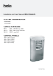
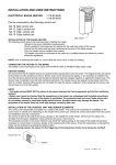
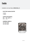
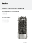
Installation and User Manual Helo Ring DE
ELECTRIC SAUNA HEATER:
1118-600-0405
1118-900-0405
CONTROL PANELS:
1601-12 (RA 12 Digi II)
1601-13 (RA 13 Digi I)
1601-16 (RA 16 Easy)
1601-18 (RA 18 Midi)
314 SKLT 34 A
2
Installation and User Manual Helo Ring
Contents
1. Quick instructions for use of the sauna heater
3
1.1.
Check before taking a sauna bath
3
1.2.
Operation of the sauna heater controls
3
2. Information for users
3
2.1.
Sauna room
3
2.2.
Recommended sauna room ventilation
4
2.3.
Heating the sauna
4
2.4.
Sauna heater stones
5
2.5.
If the sauna heater will not heat up
5
3. Instructions for the installer
6
3.1.
Preparing for sauna heater installation
6
3.2.
Installation
6
3.3.
Sauna heater safety clearances
7
3.4.
Connection of the sauna heater to the mains
8
3.5.
Electric heating toggle
8
3.6.
Locating the connecting box for the connection cable in the sauna room
9
3.7.
Principle image when Digi II is used as control panel
10
3.8.
Wiring diagram
11
4. Helo Ring spare part list
12
5. ROHS
12
Images and tables
Image 1 Recommended sauna room ventilation
4
Image 2 Location for the connection box
9
Image 3 Principle image
10
Image 4 Wiring diagram for the sauna heater
11
Table 1 Safety clearances
7
Table 2 Connection cable and fuses
8
Installation and User Manual Helo Ring
3
1. Quick instructions for use of the sauna heater
1.1. Check before taking a sauna bath
1.
2.
3.
The sauna room is suitable for taking a sauna bath.
The door and the window are closed.
The sauna heater is topped with stones that comply with the manufacturer's recommendations, the heating elements are
covered with stones, and the stones are piled sparsely.
NOTE! Ceramic rocks are not allowed.
A pleasant, smooth sauna bath temperature is about 70 °C degrees.
Rearrange the sauna stones at least once a year and replace any weathered stones. This enhances air circulation between the
stones, which extends the useful life of the heating elements.
If you encounter any problems, please contact the manufacturer's warranty service shop.
For additional information about enjoying a sauna bath, please visit our website at www.helo.fi
1.2. Operation of the sauna heater controls
The main switch is located on the side of the sign at the bottom of the sauna heater.
The sign shows the position of the switch. ( 0 I )
Refer to the specific control panel operating instructions.
2. Information for users
Persons with reduced physical and mental capacity, sensory handicap, or little experience and knowledge about how the device
is operated (e.g. children), should only operate the device while supervised or according to instructions given by the persons in
charge of their safety.
Make sure that children aren't playing with the sauna heater.
2.1. Sauna room
The walls and ceiling of a sauna room should be thermally well insulated. All surfaces that store heat, such as tiled and
plastered surfaces must be insulated. It is recommended to use wooden panel cladding inside the sauna room. If there are heat
storage elements in the sauna room, such as decorative stone, glass etc., note that these elements may extend the pre-heating
period even though the sauna room is otherwise well insulated (see page 6, section 3.1. Preparing for sauna heater installation).
4
Installation and User Manual Helo Ring
2.2. Recommended sauna room ventilation
5
C
C
A
C
C
AA
5
7
4
2
1
6
1000 mm
min
500 mm
1
4
B
3
B
3
1
Image 1 Recommended sauna room ventilation
1. Sauna room
3. Electric sauna heater
5. Exhaust flue or channel
2. Washroom
4. Exhaust valve
6. Door to the sauna room
7. A ventilation valve can be installed here to be kept closed while the sauna is heated and during bathing.
Inlet vent can be positioned in the A zone. Make sure the incoming fresh air will not interfere with (i.e. cool down) the sauna
heater's thermostat near the ceiling.
The B zone serves as the incoming air zone, if the sauna room isn't fitted with forced ventilation. In this case, the exhaust valve
is installed min 1m higher than the inlet valve.
DO NOT ISTALL INLET VALVE WITHIN ZONE C, IF THE SAUNA HEATER'S CONTROL THERMOSTAT IS LOCATED IN
THE SAME ZONE.
2.3. Heating the sauna
Before turning the sauna heater on, make sure the sauna room is suitable for taking a sauna bath. When heated for the first
time, the sauna heater may emit some odour. If you detect any odour while the sauna heater warms up, disconnect the sauna
heater briefly, and air the room. Then you can turn the sauna heater on again.
The sauna heater is turned on from the control panel that has controls for the heating temperature and
time.
The heating of a sauna should be started roughly an hour before you plan to take a sauna bath, so that the stones have time to
heat up properly and the air warms up evenly in the sauna room.
Do not put any objects on the sauna heater. Do not dry clothes on the sauna heater or anywhere in its vicinity.
Installation and User Manual Helo Ring
5
2.4. Sauna heater stones
Quality stones meet the following requirements:
1.
2.
3.
Sauna stones should withstand heat and heat variation caused by vaporisation of the water thrown on the stones.
Stones should be rinsed before use in order to avoid odour and dust.
Sauna stones should have an uneven surface to supply a larger surface for the water to evaporate from.
4.
Sauna stones should be large enough, measuring about 50–80 mm to allow good ventilation between the stones. This
extends the useful life of the heating elements.
5.
Sauna stones should be piled sparsely in order to enhance ventilation between the stones. Do not bend the heating
elements together or against the frame.
Rearrange the stones regularly (at least once a year) and replace small and broken stones with new, larger stones.
Stones are piled so that they cover the heating elements. Do not, however, pile a large heap of stones on the heating elements.
For a sufficient amount of stones refer to Table 1 on page 7. Any small stones in the package of stones must not be piled on the
sauna heater.
The warranty does not cover defects resulting from poor ventilation caused by small and tightly packed stones.
Ceramic rocks are not allowed. They may cause damage to the sauna heater that will not be covered by the warranty.
2.5. If the sauna heater will not heat up
If the sauna heater will not heat up, please check that:
- the power is on;
- the main fuses of the sauna heater are intact;
- is there any error messages on the control panel. In case of an error message on the control panel, please refer to the control
panel instructions.
Installation and User Manual Helo Ring
6
3. Instructions for the installer
THE PERSON INSTALLING THE SAUNA HEATER SHOULD LEAVE THESE INSTRUCTIONS AT THE PREMISES FOR THE
FUTURE USER.
3.1. Preparing for sauna heater installation
Check the following before installing the sauna heater.
1. The ratio of the heater's input (kW) and the sauna room's volume (m3). Volume recommendations are presented in Table 1
on page 7. The minimum and maximum volumes must not be exceeded.
2. The sauna room height must be a min. of 1900 mm.
3. Uninsulated and masonry stone walls extend the preheating time. Each square metre of plastered ceiling or wall surface adds
3
1.5 – 2 m to the sauna room's volume.
4. Check page 8 Table 2 for a suitable fuse size (A) and the correct diameter of the power supply cable (mm²) for the sauna
heater in question.
5. Conform to the specified safe clearance around the sauna heater. Please refer to Table 1 on page 7.
6. There should be enough room around the sauna heater for maintenance purposes. Also a doorway can be considered as a
maintenance area.
3.2. Installation
Follow the safety clearance specifications on page 7 when installing the sauna heater.
The sauna heater is a floor-standing model. The base must be solid, because the sauna heater weighs about 75 kg.
The sauna heater is levelled by the adjustable legs.
The sauna heater is fixed on the floor from its legs by the provided metal fasteners (2 pcs). This will keep the safety clearances
intact during use.
The minimum clearances specified on page 7 must be followed even if the sauna room wall materials are incombustible.
Walls or ceilings must not be clad with fibre-reinforced plaster board or other light-weight cladding, because they may cause a
fire hazard.
Install the sauna heater so that the sign and the warnings can be read even after the installation.
The control panels are installed outside the sauna room with the exception of the Midi controller which is installed on the wall
beside the sauna heater. Refer to more detailed installation instructions in the installation and operation guide of the control
panel.
Only a single sauna heater is allowed per sauna room
7
Installation and User Manual Helo Ring
3.3. Sauna heater safety clearances
5 9 1900
8 13 1900
To the
ceiling
6,0
8,0
In front
m3 m3 mm
kW
On the
sides
Height
min.
max.
min.
Power Saunaroom Safety clearances min. Adequate amount
of stones
mm
mm
mm
Approx. kg
100
100
100
100
1100
1100
60
60
Table 1 Safety clearances
Corner and wall installation:
The sensor is placed on the centreline of the heater
100
100
100
1100
Sensor
mm
1900
100
800
Fixing the sauna heater
on the floor. NOTE fixing
of two (2) legs
mm
Heater’s leg
Floor fastener
Metal fastener
Adjustable leg
Mid-floor installation:
Sensor
1100
Sensor
1900
100
800
100
mm
100
NOTE !
If the heater is placed more than
100 mm from the wall the
installation type is always a midfloor installation.
The sensor must be fitted to the
ceiling according to instructions.
8
Installation and User Manual Helo Ring
3.4. Connection of the sauna heater to the mains
The sauna heater must be connected to the mains by a qualified electrician and in compliance with current regulations. The
sauna heater is connected with a semi-permanent connection. Use H07RN-F (60245 IEC 66) cables or a corresponding type.
Other output cables (signal lamp, electric heating toggle) must also adhere to these recommendations. Do not use PVC
insulated cable as a connection cable for the sauna heater.
A multipolar (e.g. 7-pole) cable is allowed, if the voltage is the same. In the absence of a separate control current fuse, the
diameter of all cables must be the same, i.e. in accordance with the front fuse.
The connecting box on the sauna wall should be located within the minimum safety clearance specified for the sauna heater.
The maximum height for the connection box is 500 mm from the floor. See page 9 Image 2 Location for the connection box
If the connection box is located at over 500mm distance from the heater, the maximum height is 1000mm from the floor.
Sauna heater insulation resistance:
The sauna heater heating elements may absorb moisture from air, e.g. during storage. This may cause leakage currents. The
moisture will be gone after a few heating sessions. Do not connect the heater power supply through a ground fault interrupter.
However, adhere to the effective electrical safety regulation when installing the sauna heater.
Power
kW
6,0
8,0
Sauna heater’s
connection cable
H07RN-F /
60245 IEC 66
mm2
400 – 415V 3N~
5 x 1,5
5 x 2,5
Fuse
A
3 x 10
3 x 16
Sauna heater’s
connection cable
H07RN-F /
60245 IEC 66
mm2
230V 3~
4 x 2,5
4x6
Fuse
A
3 x 16
3 x 25
Sauna heater’s
connection cable
H07RN-F /
60245 IEC 66
mm2
230-240V 1N~/2~
3x6
3x6
Fuse
A
35
35
Table 2 Connection cable and fuses
3.5. Electric heating toggle
The electric heating toggle applies to homes with an electric heating system.
Sauna heater has a connection (marked 55) for controlling the electric heating toggle. Connector 55 and the heating elements
are simultaneously live (230V).
9
Installation and User Manual Helo Ring
3.6. Locating the connecting box for the connection cable in the sauna room
100
100
1.
500 mm
3.
200 mm
500 mm
KIUAS
2.
Image 2 Location for the connection box
100 mm = Specified minimum safety clearance
1. Recommended location for the connecting box
2. Silumin box recommended in this area.
3. This area should be avoided. Always use a silumin box.
In other areas, use a heat-resisting box (T 125 °C) and heat-resisting cables (T 170 °C). The connection box must be clear of
obstacles. When installing the connection box to zones 2 or 3, refer to the instructions and regulations of the local energy
supplier.
10
Installation and User Manual Helo Ring
3.7. Principle image when Digi II is used as control panel
Connector strip
Limiter
Heater
4
3
2
1
4
3
2
1
Sensor cable
1 Blue
2 White
3 Red
4 Yellow
1 Blue
2 White
3 Red
4 Yellow
Control panel
A1
A2
A3
A4
A5
Valk
Ruskea
Vihreä
Kelt
Harm
A 1 2 3 4 5 B1 2 3 4 5
A 1 2 3 4 5 B1 2 3 4 5
Heater
Vit
Brun
Grön
Gul
Grå
White
Brown
Green
Yellow
Grey
Weiss
Braun
Grün
Gelb
Grau
B1
B2
B3
B4
B5
Rosa
Sin
Pun
Musta
Violetti
Ljusröd
Blå
Röd
Svart
Violett
Pink
Blue
Red
Black
Violet
Rose
Blau
Rot
Schwarz
Violett
Control panel
1601 - 12
Sensor
Silicone 4 x 0,25
Sauna
heater
LiYY 10 x 0,25
230 - 240V 1N~/ 2~
Input 230V 3~
400 - 415V 3N~
Image 3 Principle image
11
Installation and User Manual Helo Ring
3.8. Wiring diagram
Teho, Effekt
Power, Leistung
Puissance, Vermogen
Potencia
Lämpövastukset, Värmeelement, Éléments chauffants
Heating elements, Heizeelement, Verwarmingselementen
Resistencias
230 V
SEPC 202
2000W
kW
SEPC 203
2670W
1,2,3
6,0
8,0
1,2,3
230V - 240V 1N~ / 2~
1
2
3
2
1
3
6
5
L2
N
L1
L2
L3
J12
W
J11
V
K1
J10
Control
N
1
2
3
1
2
3
N
1 2 3 4
Fan
1
2 3 4
5.*
)
N
N
6
4
6
5
L1 L2 L3
1A
1A
F1
T1 AH
5
400V - 415V 3N~
L
Light
4
L2 L3
L1
A 12345 B 12345
U
1234
230 V 3~
K2
1 2 3 4 5 6
4
1
Sin.
Blå
Blau
Blue
Bleu
Blauw
Azul
2
Val.
Vit
WeiB
White
Blanc
Wit
Blanco
3
Pun.
Röd
Rot
Red
Rouge
Rood
Rojo
4
Kelt.
Gul
Gelb
Yellow
Jaune
Geel
Amarillo
6.
N 55
*) Katso ohjauskeskuksen käyttöohje
1.
2.*
)
3.*
max. 100W
)
4.*
)
Se styrpanelens bruksanvisning
Sehe die Bedienungsanleitung des
Steuergerätes
See the control panel manual
Voir le manuel du panneau de commande
Zie handleiding bedieningspaneel
Consulte el manual del panel de control
1. Syöttö / Nätet / Stromnetz / Power input. / Puissance absorbée / Vermogensingang / Entrada de
alimentación
2. Saunavalo / Bastu belysning / Saunabeleuchtung / Sauna light / Éclairage du sauna /
Saunaverlichting / Luz de sauna
3. Tuuletin / Fläkt / Ventilator / Fan / Ventilation / Ventilator / Ventilación
4. Sähkölämmityksen vuorottelu / Alternering med elvärme / Signal kontakt / Signal contact / Contact
du signal / Signaalcontact / Contacto señal
5. Ohjauskeskus / Styrpanel / Steuergerät / Control panel. / Panneau de commande / Bedieningspaneel
Panel de control
6. Tuntoelin / Sensor / Fühler / Sensor / Capteur / Sensor
354 SKLT 5 B
Image 4 Wiring diagram for the sauna heater
12
Installation and User Manual Helo Ring
4. Helo Ring spare part list
Part
Part number
Part name
Helo Ring 600
Helo Ring 900
1
5916229
Circuit board OLEA 57
1
1
2
6214032
Sensor OLET 19
1
1
3
7812550
Mains connector NLWD 1-1
1
1
4
5716203
Relay Finder
2
2
5
6119649
Rocker switch
1
1
6
7306611
Rubber cover for rocker switch
1
1
7
7801711
Fuse F1 T1 AH
1
1
8
4316221
Heating element SEPC 202 2000W / 230V
3
-
8
5207518
Heating element SEPC 203 2670W / 230V
-
3
9
6216410
Circuit board OLEA 83 (Heater with Midi control panel)
1
1
5. ROHS
Ympäristönsuojeluun liittyviä ohjeita
Anvisningar för miljöskydd
Tämän tuotteen käyttöiän päätyttyä sitä ei
saa hävittää normaalin talousjätteen
mukana, vaan se on toimitettava
sähkö- ja elektroniikkalaitteiden kierrätykseen
tarkoitettuun keräyspisteeseen.
Denna produkt får inte kastas med
vanliga hushållssopor när den
inte längre används. Istället ska den
levereras till en återvinningsplats
för elektriska och elektroniska apparater.
Symboli tuotteessa,
käyttöohjeessa tai
pakkauksessa tarkoittaa sitä.
Symbolen på produkten,
handboken eller
förpackningen refererar till detta.
Valmistusaineet ovat kierrätettävissä merkintänsä
mukaan. Käytettyjen laitteiden
uudelleenkäytöllä, materiaalien hydöyntämisellä
tai muulla uudelleenkäytöllä teet arvokkaan teon
ympäristömme hyväksi.
Tuote palautetaan ilman kiuaskiviä ja verhouskiviä
kierrätyskeskukseen.
De olika materialen kan återvinnas enligt
märkningen på dem. Genom att återanvända,
nyttja materialen eller på annat sätt återanvända
utsliten utrustning, bidrar du till att skydda vår
miljö.
Produkten returneras till återvinningscentralen
utan bastusten och eventuell täljstensmantel.
Tietoa kierrätyspaikoista saat
kuntasi palvelupisteestä.
Vänligen kontakta de kommunala myndigheterna
för att ta reda på var du hittar närmaste
återvinningsplats.
Instructions for environmental protection
Hinweise zum Umweltschutz
This product must not be disposed with
normal household waste at the end of
its life cycle. Instead, it should be
delivered to a collecting place for the recycling
of electrical and electronic devices.
Dieses Produkt darf am Ende seiner LebensDauer nicht über den normalen Haushaltsabfall
Entsorgt werden, sondern muss an einem
Sammelpunkt für das Recycling von elektrischen
und elektronischen Geräten abgegeben werden.
The symbol on the product, the
instruction manual or the
package refers to this.
Das Symbol auf dem produkt, der
Gebrauchsanleitung oder der
Verpackung weist darauf hin.
The materials can be recycled according to the
markings on them. By reusing, utilising the
materials or by otherwise reusing
old equipment, you make an important
contribution for the protection of our environment.
Please note that the product is returned to the
recycling centre without any sauna rocks and
soapstone cover.
Please contact the municipal administration
with enquiries concerning the recycling place.
Die Werkstoffe sind gemäß ihrer Kennzeichnung
wiederverwertbar, Mit der Wiederverwendung,
der stofflichen Verwertung oder anderen Formen
der Verwertung von Altgeräten leisten Sie einen
wichtigen Beitrag zum Schutze unserer Umwelt.
Dieses Produkt soll ohne Steine und
Specksteinmantel an dem Sammelpunkt für
Recycling zurückgebracht werden.
Bitte erfragen Sie bei der Gemeindeverwaltung
die zuständige Entsorgungsstelle.