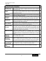
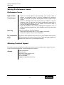
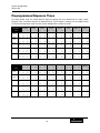
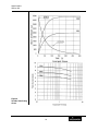
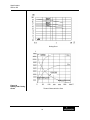
1
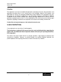
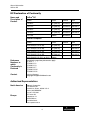
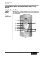
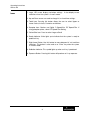
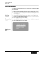
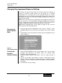
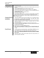
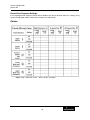
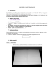
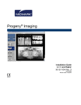
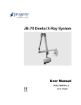
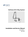
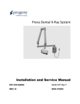
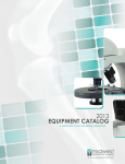
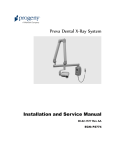
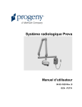
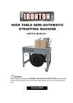
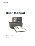
VetPro® DC Animal Health Dental X-ray System User Manual 00-02-1601 Rev. H ECN: P3415 Midmark Corporation 675 Heathrow Drive Lincolnshire, Illinois 60069 U.S.A. Phone: 800-MIDMARK Fax: (847) 415-9801 midmarkanimalhealth.com VetPro® DC Animal Health Dental X-ray System User Manual Midmark Corporation 675 Heathrow Dr. Lincolnshire, Illinois 60069 U.S.A. Phone: 800-MIDMARK Fax: (847) 415-9801 midmarkanimalhealth.com © Midmark Corporation 2014, U.S. Patents D470237, D469182, D470589, 6,837,468, and 6,664,853 Table of Contents VetPro® DC Table of Contents TABLE OF CONTENTS ...................................................................................................................................................... I GENERAL INFORMATION ...........................................................................................................................................1 INDICATIONS FOR USE ....................................................................................................................................................1 CONTRAINDICATIONS .....................................................................................................................................................1 WARNINGS / PRECAUTIONS ............................................................................................................................................1 X-RAY PROTECTION: ................................................................................................................................................2 PRODUCT DESCRIPTION .................................................................................................................................................3 COMPLIANCE WITH APPLICABLE STANDARDS .....................................................................................................................5 CERTIFIED COMPONENTS ...............................................................................................................................................5 EC DECLARATION OF CONFORMITY .................................................................................................................................6 AUTHORIZED REPRESENTATIVES ......................................................................................................................................6 EXPLANATION OF SYMBOLS ON TECHNICAL LABELS ...........................................................................................................7 OBTAINING TECHNICAL SUPPORT ....................................................................................................................................7 OPERATING THE VETPRO® DC ANIMAL HEALTH DENTAL X-RAY SYSTEM.........................................................8 USING THE OPERATOR PANEL .........................................................................................................................................8 TAKING AN X-RAY ........................................................................................................................................................ 11 USING THE 30 MM CONE (30-A2200) ............................................................................................................................ 12 RECOMMENDED MAINTENANCE ............................................................................................................................ 13 REGULAR MAINTENANCE .............................................................................................................................................. 13 CLEANING AND DISINFECTING........................................................................................................................................ 13 CHECKING SYSTEM FUNCTIONS ............................................................................................................................ 14 SYSTEM FUNCTION CHECKLIST ..................................................................................................................................... 15 NEW TUBE SEASONING PROCEDURE .............................................................................................................................. 16 SOLVING PERFORMANCE ISSUES .......................................................................................................................... 17 PERFORMANCE ISSUES................................................................................................................................................. 17 OBTAINING TECHNICAL SUPPORT .................................................................................................................................. 17 IF THE ABOVE STEPS DO NOT RESOLVE ANY OF THE ERROR ISSUES THAT YOU ARE EXPERIENCING, SUSPEND USE OF THE X-RAY UNIT AND CONTACT MIDMARK TECHNICAL SUPPORT FOR ASSISTANCE........................................................................................ 17 PREPROGRAMMED EXPOSURE TIMES .................................................................................................................. 18 BASELINE TECHNIQUE CHARTS – CANINE BASELINE TECHNIQUE CHARTS USE THE CHARTS BELOW FOR RECORDING ACCEPTABLE SETTINGS ................................................................................................................... 19 FELINE TECHNIQUE SETTINGS ............................................................................................................................... 20 CHANGING LANGUAGE ............................................................................................................................................ 21 SYSTEM CONFIGURATION ....................................................................................................................................... 22 SYSTEM CONFIGURATION MODE ................................................................................................................................... 22 ADJUSTING THE DISPLAY .............................................................................................................................................. 23 CHANGING PREPROGRAMMED EXPOSURE SETTINGS ........................................................................................................ 24 SHOWING CURRENT SYSTEM CONFIGURATION ................................................................................................................ 28 CHANGING THE CONE SIZE ........................................................................................................................................... 29 DIAGNOSTIC MODE ...................................................................................................................................................... 30 SPECIFICATIONS ....................................................................................................................................................... 31 VETPRO® DC ANIMAL HEALTH DENTAL X-RAY SYSTEM .................................................................................................. 31 i General Information VetPro® DC General Information Indications for Use The VetPro® DC Animal Health Dental X-ray System is to be used by veterinarian and other qualified professionals as an extraoral source of X-rays in Dental radiography. Contraindications None known Warnings / Precautions Radiation Safety • • • • Electrical Safety • • • • Explosion Safety Only qualified and authorized personnel may operate this equipment observing all laws and regulations concerning radiation protection. The operator at all times must remain 6ft. (2m) from the focal spot and the X-ray beam for operator protection. Full use must be made of all radiation safety features on the equipment. Full use must be made of all radiation protection devices, accessories and procedures available to protect the patient and operator from X-ray radiation. Only qualified and authorized service personnel should remove covers on the equipment. This equipment must only be used in rooms or areas that comply with all applicable laws and recommendations concerning electrical safety in rooms used for medical purposes, e.g., IEC, US National Electrical code, or VDE standards concerning provisions of an additional protective earth (ground) terminal for power supply connection. Before cleaning or disinfecting, this equipment must always be disconnected from the main electrical supply. The VetPro® DC Animal Health Dental X-ray System is ordinary type medical equipment without protection against ingress of liquids. To protect against short-circuit and corrosion, no water or any other liquid should be allowed to leak inside the equipment. This equipment must not be used in the presence of flammable or potentially explosive gases or vapors, which could ignite, causing personal injury and/or damage to the equipment. If such disinfectants are used, the vapor must be allowed to disperse before using the equipment. 1 General Information VetPro® DC Attention: The equipment must only be installed and operated in accordance with the safety procedures and operating instructions given in this manual and in the Installation Guide for the purposes and applications for which it was designed. Modifications and/or additions to the equipment may only be carried out by Midmark Corporation or by third parties expressly authorized by Midmark Corporation to do so. Such changes must comply with legal requirements as well as with the generally accepted technical rules. It is the responsibility of the user to ensure that existing legal regulations regarding installation of the equipment with respect to the building are observed. Caution: Do not hang lead aprons on the horizontal extension arm. X-RAY PROTECTION: X-ray equipment may cause injury if used improperly. The instructions contained in this manual must be read and followed when operating the VetPro® DC. Your Midmark Sales Corporation dealer will assist you in placing the VetPro® DC in operation. The VetPro® DC Animal Health Dental X-ray System provides a high degree of protection from unnecessary X-radiation. However, no practical design can provide complete protection nor prevent operators from exposing themselves or others to unnecessary radiation. 2 General Information VetPro® DC Product Description The VetPro® DC Animal Health Dental X-ray System is a state-of-the-art, high-frequency intra-oral X-ray machine. The VetPro® DC consists of five components, as shown in Figure 1 Component Diagram: the Control Unit, the Tubehead, the Articulating Arm, the Horizontal Arm, the Cone, and the Remote Control option. Control Unit The Control Unit provides for the input power connection and control of the Tubehead and Operator Panel. It provides automatic line voltage compensation, kVp control, and exposure time control. The Control Unit consists of the mounting base and Operator Panel. Tubehead The Tubehead contains the X-ray tube, high voltage circuit, and Cone. It is shipped already assembled to the Articulating Arm. Note: There is a small hole in the plastic handle covering the back of the Tubehead. Under no circumstances should this hole be blocked as it provides an air vent to allow the Tubehead oil to expand and contract as the unit is operated. Articulating Arm The Articulating Arm provides the articulation support for the Tubehead and the reach and coverage of the Tubehead to the patient. It allows smooth movement for precise positioning and does not drift or vibrate when left in position. Horizontal Arm The Horizontal Arm helps provide the necessary reach for the VetPro® DC. It pivots smoothly around a shaft inserted in the top of the Control Unit and contains an access cover to connect the cable from the Horizontal Arm to the Control Unit. It is available in four lengths, providing reaches of 56, 66, 76 and 82 inches. Modular Beam Limiting Device [BLD] The cone establishes the distance from the X-ray tube to the patient’s skin. It provides positioning assistance and collimates the X-ray beam to within a defined circle at its end. The VetPro® DC is shipped with the standard 20 mm Cone attached to the Tubehead. A 30 mm Cone [30A2200] can be ordered as an option. Remote Control The remote control switch is used to make exposures in addition to or replacing the use of the exposure button. Mobile Unit An optional device, the mobile unit supports preprogrammed technique selections and X-ray acquisition. See Appendix A of the VetPro Installation and Service Manual for the installation instructions of the mobile unit. Installation and Service The VetPro® DC Animal Health Dental X-ray System should only be installed and serviced by approved Midmark dealer personnel. Contact Midmark Sales Corporation at 800-MIDMARK if you need assistance locating an approved dealer. 3 General Information VetPro® DC Figure 1 Component Diagram Caution: Do not hang lead aprons on the horizontal extension arm. 4 General Information VetPro® DC Compliance with Applicable Standards The certified components of the VetPro® DC Animal Health Dental X-ray System comply with Radiation Performance Standards 21 CFR, Subchapter J, at the time of manufacture. Radiation Protection The certified components of the VetPro® DC Animal Health Dental X-ray System comply with IEC 60601-1-3 Radiation protection/X-ray equipment. UL 2601-1 File Number: E181750 Classified by Underwriters Laboratories Inc. with respect to electrical shock, fire and mechanical hazards only in accordance with UL 2601-1, and CAN/CSA C22.2 NO, 601.1-M90, and to the following particular standards, IEC60601-2-7, IEC60601-2-28. EMI/EMC IEC60601-1-2 Certified Components System Component Tubehead Control Unit. VetPro® DC Mobile Control Unit. VetPro® DC Modular BLD, 20 cm Lg., 70 mm Cone, Gray Modular BLD, 30 cm Lg., 70 mm Cone, Gray Modular BLD, 20 cm Lg., 60 mm Cone, White Modular BLD, 30 cm Lg., 60 mm Cone, White Modular BLD, 30 cm Lg., 60 mm Cone, White Modular BLD, 20 cm Lg., 30x40 mm Cone, White Modular BLD, 30 cm Lg., 30x40 mm Cone, White Modular BLD, 20 cm Lg., 20x30 mm Cone, White Modular BLD, 20 cm Lg., 35x45 mm Cone, Gray Modular BLD, 20 cm Lg., 35x45 mm Cone, White Modular BLD, 30 cm Lg., 35x45 mm Cone, Gray Modular BLD, 30 cm Lg., 35x45 mm Cone, White Modular BLD, Base, Gray Modular BLD, Spacer, Gray Modular BLD, Spacer, White 5 Reference Number 30-A1027 30-A0018 30-A0019 30-A2195 30-A2200 30-A2196 30-A2201 30-A2229 30-A2198 30-A2203 30-A2199 30-A2221 30-A2222 30-A2223 30-A2224 30-A2205 30-A2206 30-A2208 General Information VetPro® DC EC Declaration of Conformity Name and Description of Product VetPro® DC System Reach Control Arm P7018V-P 82”[208 cm] 30-A0019 30-A2164 P7017V-P 76”[208 cm] 30-A0019 30-A2071 P7016V-P 66”[208 cm] 30-A0019 30-A2073 P7015V-P 56”[208 cm] 30-A0019 30-A2074 P7017VM Mobile 30-A0018 System Reach Control DCV8-G2A/(S1, S2 or SB) 82”[208 cm] 30-A2213 DCV7-G2A/(S1, S2 or SB) 76”[208 cm] 30-A2212 DCV6-G2A/(S1, S2 or SB) 66”[208 cm] 30-A2211 DCV5-G2A/(S1, S2 or SB) 56”[208 cm] 30-A2210 DCV5-G2A/(S1, S2, S1/L or S2/L) Mobile VetPro® Complete Reference Numbers to which Conformity is Declared The following regulatory documents apply: UL 2601-1 IEC 60601-1-2 IEC 60601-1-3 IEC 60601-2-7 IEC 60601-2-28 IEC 60601-2-32 Contact Technical Support [email protected] Authorized Representatives North America Midmark Corporation 675 Heathrow Dr. Lincolnshire, Illinois 60069 U.S.A. Phone: 800-MIDMARK Fax: 847-415-9801 Europe CE Partner 4U Esdoornlaan 13 3951DB Maarn The Netherlands www.cepartner4u.eu 6 Arm General Information VetPro® DC Explanation of Symbols on Technical Labels Type B: Protection against electric shock (IEC 60601.1-1988) Consult written instructions in User Manual. ATTENTION RAYONS-X: OPERATION SEULEMENT PAR DU PERSONNEL AUTORISE. VOIR MANUEL DE L’OPERATEUR. WARNING X-RAY THIS X-RAY UNIT MAY BE DANGEROUS TO PATIENT AND OPERATOR UNLESS SAFE EXPOSURE FACTORS AND OPERATING INSTRUCTIONS ARE OBSERVED. X-RAY EMISSION Mains HOT WIRE Mains NEUTRAL WIRE Earth Ground Obtaining Technical Support Contact Midmark Corporation 675 Heathrow Dr. Lincolnshire, Illinois 60069 U.S.A. Phone: 800-MIDMARK Fax: 847-415-9801 [email protected] 7 Operating Instructions VetPro® DC Operating the VetPro® DC Animal Health Dental X-ray System Using the Operator Panel Power On Settings When the VetPro® DC Animal Health Dental X-ray System is powered on, the Operator Panel selections are those that were in use when the system was last powered off. Figure 2 VetPro® DC Operator Panel 1 2 7 3 4 5 6 8 9 8 Operating Instructions VetPro® DC Icons 1. Large, LED screen displays technique settings. It also displays menu selections when the system is in menu mode. 2. Up and Down arrows are used to change kV, mA and time settings. 3. Tooth Icon: Pressing this button allows the user to select Upper or Lower Canine, Incisors, Premolars and Molars. 4. Receptor Icon: Choices are: Digital, D Speed film, E/F Speed Film. If using phosphor plates, select E/F Speed Film Setting. 5. Patient Size Icon: Press to select Large or Small 6. Ready Indicator: Circle lights up to indicate that the system is ready to produce X-ray. 7. Right Arrow Button: Use this button to move between kV, mA and time selections. This button is also used as an “Enter” key when the system is in menu mode. 8. Radiation Indicator: This symbol lights up when an X-ray is produced. 9. Exposure Button: Pressing this button will produce an X-ray exposure. 9 Operating Instructions VetPro® DC Exposure Settings When the system is powered on, the operator panel, Figure 2, displays the exposure settings (kV, mA, and seconds) for the currently selected tooth, image receptor type, and patient size. Use the Tooth Selection, Image Receptor Type, and Patient Size buttons to select other exposure settings. For a table of the factory-programmed exposure settings, refer to the Preprogrammed Exposure Settings tables on page 18 in this manual. Adjusting Exposure Settings Preset exposure settings can be adjusted prior to making an exposure. Use the right arrow to select the exposure setting to adjust. Then use the up and down arrow buttons to adjust the value. To save new presets, use System Configuration mode described on page 22 in this manual. Exposure Button and Ready Indicator The Exposure button is used to initiate an X-ray exposure. For a complete exposure, the button must be pressed and held until the Radiation Indicator no longer illuminates and the audible signal is no longer heard. Releasing the Exposure button immediately terminates the X-ray exposure. CAUTION! Releasing the Exposure button prior to the completion of the X-ray exposure will result in an incomplete exposure of the image. This may require the operator to re-take the radiograph. When a premature release of the Exposure button occurs, the system will notify the operator momentarily and then return to operating mode. Ready Indicator The Ready Indicator illuminates when the system is ready to make an exposure. Immediately after an exposure, the Ready Indicator flashes until the X-ray tube cools down sufficiently to make the next exposure. When the Ready Indicator is flashing, no exposure can be made. Radiation Indicators The VetPro® DC has a visible and an audible Radiation Indicator. When an exposure is in progress, the Radiation Indicator on the Operator Panel is illuminated and an audible tone is heard. The exposure is complete when the Radiation Indicator is extinguished and the audible tone is no longer heard. 10 Operating Instructions VetPro® DC Taking an X-ray 1. Turn the power switch, located at the upper right of the Control Unit, to the “On” position. The Ready Indicator on the front of the Operator Panel, (Figure 2), will light. 2. Verify that the unit is set for the correct Image Receptor Type. The icon for the currently selected Image Receptor Type is illuminated. To change the Image Receptor type, press the Image Receptor Type button until the correct Image Receptor Type is selected. 3. Verify that the system is set for the appropriate Patient Size. The icon for the currently selected Patient Size is illuminated. The change the Patient Size, press the Patient Size button until the correct Patient Size is selected. 4. Verify that the unit is set for the Tooth to be imaged. The icon for the currently selected Tooth is illuminated. To change the Tooth Selection, press the Tooth Selection button until the correct Tooth is selected. 5. If desired, preset exposure settings for the combination of Image Receptor Type, Tooth Selection, and Patient size, selected in steps 2-4, can be adjusted prior to making an exposure. Use the right arrow to select the exposure setting to adjust. Then use the up and down arrow buttons to adjust the value. Skip this step if you are using preprogrammed exposure settings. Note: When exposure settings are being adjusted, the Tooth Selection, Image Receptor Type, and Patient Size buttons are turned off. 6. Position the Tubehead to the patient using standard accepted positioning procedures. 7. Press and hold the Exposure button until the audible signal is no longer heard and the Radiation Indicator is no longer illuminated. Releasing the Exposure button or coil-cord hand switch at any time will immediately terminate the exposure. Note: When using the coil-cord hand switch, it is recommended that the operator exit the operatory if possible. Note: In order to comply with regulations and good safety practices, the technique factors must be visible to the operator from the remote location. 8. Return the Tubehead to the storage position. Note: Be careful not to strike the Tubehead on anything when returning it to the storage position. It may be necessary to increase or decrease the kV, mA, or time from the preset values for one exposure. To do so: 1. Press the Enter button to highlight the value to change. 2. Use the up or down button to increase or decrease the value (no lights on the display will be lit to indicate the preset values). 3. Press the Exposure button. 4. Press any other button (Tooth, Film or Patient Size) to return the display to the preset values. 11 Operating Instructions VetPro® DC Using the 30 mm Cone (30-A2200) The VetPro® DC Animal Health Dental X-ray System is factory set for use with the standard supplied 8 inch [20 cm] Cone. The 12 inch [30 cm] Cone [30-A2200] is available. Using the longer cone requires longer exposure times. See the System Configuration section on page 22 of this manual for instructions to set the system to use the longer cone. 12 Recommended Maintenance VetPro® DC Recommended Maintenance Regular Maintenance In the interest of equipment safety, a regular maintenance program must be established. This maintenance program should consist of annual system function checking. It is the owner’s responsibility to arrange for this service and to assure that the personnel performing this are fully qualified to service Midmark Corporation X-ray equipment. Cleaning and Disinfecting Employ personal protective equipment to prevent the spread of infections Clean the outside of the system using a damp towel or non-alcohol based disinfectant. Cleaning / Disinfecting CAUTION: • Do not allow liquids to drip into the system electronics. • Do not spray cleaner or disinfectant directly onto the machine. • Protect the system from contamination using barriers available from animal health distributors. • Follow the disinfectant manufacturer’s recommendations when using their cleaner or disinfectant. Cleaning Methods If not using a barrier, between each patient, perform the following cleaning and disinfecting steps. 1. Remove gross bio-burden from the cone, handles and structure with a disposable towel moistened with water. 2. Dry the cone, handles and structure with disposable towels. 3. Wipe the cone, handles and structure with a germicidal broad spectrum disinfectant product following the disinfectant manufacturer’s instructions. 4. Clean any remaining disinfectant residue from the system with a disposable towel moistened with water. This additional step prevents possible product discoloration or corrosion. 5. Dry the cone, handles and structure with paper towels. Caution! The VetPro® DC Animal Health Dental X-ray System is not waterproof. Use only moistened, not saturated, towels. 13 Checking System Functions VetPro® DC Checking System Functions The following checks must be performed to complete the installation of the VetPro® DC Animal Health Dental X-ray System and as part of the recommended maintenance as indicated in the User Manual. Failure to perform these checks may result in an installation that does not comply with U.S. Radiation Performance Standards 21 CFR Subchapter J. CAUTION! If the VetPro® DC Animal Health Dental X-ray System does not perform the functions below the system is not to be used. See the Troubleshooting section of the Installation Guide or contact Midmark Corporation’s Technical Support. 14 Checking System Functions VetPro® DC System Function Checklist Wall Mounting Ensure that the wall support is adequate and that the system is properly mounted to the wall. Labels Ensure that all certified components bear labels that include the model and serial number, date of manufacture and a statement of certification as noted elsewhere in this manual. Tubehead Check for oil leaks or other evidence that could indicate internal damage. Replace the Tubehead, if necessary. Tubehead Rotation Ensure that the Tubehead maintains its position around the horizontal axis while remaining easy to rotate and position. Also check the vertical pivot of the Tubehead for easy movement while remaining in position after moving. Suspension Check that all movements are smooth and quiet. Verify that the Tubehead is properly counterbalanced for vertical drift and that the Horizontal and Articulating Arms do not drift horizontally. Power Switch Verify that the switch is working properly and that the Ready Indicator is illuminated when the power switch is in the ON position. Operator Panel Controls With the power switch, located at the upper right of the Control Unit, in the ON position, verify that technique factors appear on the Operator Panel. Also, check the function of the selection buttons for Tooth Selection, Image Receptor Type and Patient Size. Pressing a selection button should cause indicator lamps to indicate the selected item. Exposure Button Verify that the Exposure button on the Operator Panel is functioning properly. To make an exposure, press and hold the Exposure button until the Radiation Indicator is extinguished and the audible signal is no longer heard. Exposure Indicators Make several exposures and verify that the Radiation Indicator illuminates and the audible signal is heard. Premature Termination Select the longest exposure time possible using the up and down arrows. Initiate an exposure but release the Exposure button after a brief period of time before the timer terminates the exposure. Verify that the display indicates “Pre-termination Error” and returns to normal operating mode. Coil-cord Hand Switch Option If a coil-cord hand switch is used, inspect the switch housing and coil cord for damage or wear. Replace if evidence of damage is present. User Information Make certain that the user of the system has received the User Manual. 15 Checking System Functions VetPro® DC New Tube Seasoning Procedure X-ray tubes that sit dormant for several months can become electrically unstable. To remedy this condition, it is recommended you perform a new tube seasoning procedure. This process establishes stable high voltage operation and will ultimately extend the life of the tube. Repeat this procedure before returning to normal operation any time the system has been unused for more than two months. 1. Verify system operation. 2. Energize the system. 3. Select 60 kilovolts [kV], 7 milliamperes [mA], and the exposure time of one second. 4. Make five exposures at this level, observing the normal cooling time. 5. Select 65 kilovolts, 7 milliamperes, and the exposure time of one second. 6. Make five exposures at this level, observing the normal cooling time. 7. Select 70 kilovolts, 6 milliamperes, and the exposure time of one second. 8. Make five exposures at this level, observing the normal cooling time. 16 Solving Performance Issues VetPro® DC Solving Performance Issues Performance Issues Light or Dark X-ray Images 1. Adjust the selected exposure time, kilovoltage [kV] or tube current to produce an acceptable image. If necessary, reprogram the techniques factors, as explained in the System Configuration section on page 22 of this manual. 2. Verify the kilovoltage and tube current during an exposure using the diagnostic mode, as explained in the System Configuration section (pg. 22) of this manual. Alternatively, you may employ a non-invasive meter to evaluate kilovoltage and exposure time. 3. Inspect the condition of the remaining imaging chain components such as the film, chemistry and processor, or the condition of the X-ray sensor and computer. No X-ray If no X-ray is produced, check the following: 1. Verify that the line cord (if one is in use) is properly connected. 2. Verify that the power switch is in the ON position. Pre-termination Error Early release of the exposure switch will cause a pre-termination error to occur. After five seconds, the system will return to the normal operating condition. Be advised that this will result in an underexposed image. Obtaining Technical Support If the above steps do not resolve any of the error issues that you are experiencing, suspend use of the X-ray unit and contact Midmark Technical Support for assistance. Contact Midmark Corporation 675 Heathrow Dr. Lincolnshire, Illinois 60069 U.S.A. Phone: 1-800-MIDMARK Fax: 847-415-9801 [email protected] 17 System Configuration VetPro® DC Preprogrammed Exposure Times The tables below show the factory default exposure settings for each combination of Tooth, Image Receptor Type, and Patient Size on the Operator Panel. These exposure settings can be modified using the System Configuration mode. See the System Configuration section for details. 8" Cone Progeny Setting Schick Dexis Kodak Sirona PSP D Speed E/F Speed Large Small Large Small Large Small Large Small Large Small Large Small Large Small Large Small Upper kV 65 65 65 65 60 60 65 65 65 65 65 65 65 65 65 65 Canine mA 7 7 7 7 7 7 7 7 7 7 7 7 7 7 7 7 Sec 0.100 0.080 0.080 0.050 0.125 0.080 0.100 0.064 0.080 0.050 0.125 0.080 0.250 0.160 0.125 0.080 Lower kV 65 65 65 65 60 60 65 65 65 65 65 65 65 65 65 65 Canine mA 7 7 7 7 7 7 7 7 7 7 7 7 7 7 7 7 Sec 0.080 0.064 0.064 0.040 0.100 0.080 0.080 0.064 0.064 0.040 0.100 0.080 0.200 0.160 0.100 0.080 65 Incisors Premolars Molars kV 65 65 65 65 60 60 65 65 65 65 65 65 65 65 65 mA 7 7 7 7 7 7 7 7 7 7 7 7 7 7 7 7 Sec 0.100 0.080 0.064 0.040 0.100 0.080 0.080 0.064 0.064 0.040 0.100 0.080 0.200 0.160 0.100 0.080 65 kV 65 65 65 65 60 60 65 65 65 65 65 65 65 65 65 mA 7 7 7 7 7 7 7 7 7 7 7 7 7 7 7 7 Sec 0.100 0.080 0.064 0.040 0.100 0.080 0.080 0.064 0.064 0.040 0.100 0.080 0.200 0.160 0.100 0.080 65 kV 65 65 65 65 60 60 65 65 65 65 65 65 65 65 65 mA 7 7 7 7 7 7 7 7 7 7 7 7 7 7 7 7 Sec 0.125 0.080 0.080 0.050 0.125 0.080 0.100 0.064 0.080 0.050 0.125 0.080 0.250 0.160 0.125 0.080 12" Cone Setting Progeny Schick Dexis Kodak Sirona PSP D Speed E/F Speed Large Small Large Small Large Small Large Small Large Small Large Small Large Small Large Small Upper kV 65 65 65 65 60 60 65 65 65 65 65 65 65 65 65 65 Canine mA 7 7 7 7 7 7 7 7 7 7 7 7 7 7 7 7 Sec 0.200 0.160 0.160 0.100 0.250 0.160 0.200 0.125 0.160 0.100 0.250 0.160 0.500 0.320 0.250 0.160 Lower kV 65 65 65 65 60 60 65 65 65 65 65 65 65 65 65 65 Canine mA 7 7 7 7 7 7 7 7 7 7 7 7 7 7 7 7 Sec 0.160 0.125 0.125 0.080 0.200 0.160 0.160 0.125 0.125 0.080 0.200 0.160 0.400 0.320 0.200 0.160 65 Incisors Premolars Molars kV 65 65 65 65 60 60 65 65 65 65 65 65 65 65 65 mA 7 7 7 7 7 7 7 7 7 7 7 7 7 7 7 7 Sec 0.200 0.160 0.125 0.080 0.200 0.160 0.160 0.125 0.125 0.080 0.200 0.160 0.400 0.320 0.200 0.160 65 kV 65 65 65 65 60 60 65 65 65 65 65 65 65 65 65 mA 7 7 7 7 7 7 7 7 7 7 7 7 7 7 7 7 Sec 0.200 0.160 0.125 0.080 0.200 0.160 0.160 0.125 0.125 0.080 0.200 0.160 0.400 0.320 0.200 0.160 65 kV 65 65 65 65 60 60 65 65 65 65 65 65 65 65 65 mA 7 7 7 7 7 7 7 7 7 7 7 7 7 7 7 7 Sec 0.250 0.160 0.160 0.100 0.250 0.160 0.200 0.125 0.160 0.100 0.250 0.160 0.500 0.320 0.250 0.160 Note: Large = over 40 lbs. Small = under 40 lbs. 18 System Configuration VetPro® DC Baseline Technique Charts – Canine Baseline Technique Charts Use the charts below for recording acceptable settings D speed film Small Dog kV mA Secs Medium Dog kV mA Secs Large Dog kV mA Secs Small Dog kV mA Medium Dog Secs. kV mA Secs. Large Dog kV mA Secs. Maxillary incisors Maxillary canine Maxillary anterior premolars Maxillary PM4 Maxillary PM4 caudal view Maxillary M1 M2 Mandibular incisors Mandibular canine Mandibular anterior premolars (lateral oblique view) Mandibular posterior pm & molars Digital Maxillary incisors Maxillary canine Maxillary anterior premolars Maxillary PM4 Maxillary PM4 caudal view Maxillary M1 M2 Mandibular incisors Mandibular canine Mandibular anterior premolars (lateral oblique view) Mandibular posterior pm & molars 19 System Configuration VetPro® DC Feline Technique Settings D speed film Maxillary incisors kV 60 mA 7 Secs 0.1 Maxillary canine 60 7 0.1 Maxillary premolars M1 intraoral 60 7 0.1 Maxillary premolars M1 extraoral 60 7 0.125 Mandibular incisors and canine 60 7 0.1 Mandibular PM3 lateral oblique 60 7 0.16 Mandibular PM3 M1 60 7 0.1 Maxillary incisors kV 60 mA 7 Secs. 0.032 Maxillary canine 60 7 0.032 Maxillary premolars M1 intraoral 60 7 0.04 Maxillary premolars M1 extraoral 60 7 0.05 Mandibular incisors and canine 60 7 0.032 Mandibular PM3 lateral oblique 65 7 0.025 Mandibular PM3 M1 65 7 0.025 Digital 20 System Configuration VetPro® DC Changing Language Five languages are preprogrammed in the display panel. To change follow the steps below. 1. Push and hold the Tooth and Patient selection switches, a menu screen will appear after about 5 seconds. (See Figure 3) 2. Using the down arrow highlight “Configure Unit” and press the right arrow key. (See Figure 3) 3. “Select Languages” on the next screen is highlighted press the right arrow key. 4. Select the desired language and press the right arrow key. If you do not see your desired language listed arrow down to “More” and press the right arrow key. 5. After selection arrow down to Exit and press the right arrow key then repeat this procedure to return to the main screen. Figure 3 VetPro® DC Operator Panel 21 System Configuration VetPro® DC System Configuration System Configuration Mode About System Configuration Mode The VetPro® DC Animal Health Dental X-ray System has a software-driven system configuration mode. When the VetPro® DC is in system configuration mode, you can perform the following procedures: • Adjusting the Display • Changing Preprogrammed Exposure Settings • Changing the Cone Size • Showing Current System Configuration • Displaying Diagnostic Data Using System Configuration Mode 1. To enter system configuration mode, depress the Tooth Selection and Patient Size Selection buttons on the Operator Panel simultaneously for 5 seconds. The display shows the Main System Configuration menu, as shown in Figure 4, and the Ready Indicator blinks. 2. To select menu items while in system configuration mode, use the up and down arrows to highlight a menu option. Then use the right arrow button as an Enter button to select the highlighted option. When changing presets, the right arrow button is also used to select the technique factor. 3. After selecting a menu option, use the up and down arrows to increase or decrease values. Figure 4 Main System Configuration Menu 22 System Configuration VetPro® DC Adjusting the Display The VetPro® DC Animal Health Dental X-ray System allows the operator to adjust the display image. 1. From the system configuration main menu, shown in Figure 4, select ADJUST DISPLAY. You will see the Display Options menu shown in Figure 5. 2. Selecting EXIT returns the display to the Main System Configuration menu shown in Figure 4. Adjusting Contrast 1. Select ADJUST CONTRAST from the menu. You will see the Progeny® logo. 2. Use the up and down arrows to increase or decrease the contrast between the menu text and the display background. 3. Press the right arrow to save your settings. Reversing the Image 1. Select REVERSE IMAGE from the menu. The text and display background colors will be swapped. 2. Press the right arrow to save your settings. Figure 5 Display Options Menu 23 System Configuration VetPro® DC Changing Preprogrammed Exposure Settings The VetPro® DC Animal Health Dental X-ray System allows the operator to increase or decrease image density for all presets for a receptor simultaneously or to change each of the technique factors for a preset individually. You can also restore factory default settings. For charts of the factory default settings, refer to Factory Preprogrammed Exposure Settings on page 18 in this manual. Note: If the 12 inch [30 cm] cone is going to be used, configure the VetPro® DC for use with the 12 inch cone before changing preprogrammed exposure settings. Configuring the VetPro® DC for use with the 12 inch cone will reset exposure settings to the default settings used with the 12 inch cone. Note: Before changing presets, use the tables on pages 26 and 27 to write down the presets you are programming. Displaying the Preset Options Menu 1. From the Main System Configuration menu, shown in Figure 4, select CHANGE PRESETS. You will see the Preset Options menu shown in Figure 6. 2. Selecting EXIT returns the display to the Main System Configuration menu shown in Figure 4. Figure 6 Preset Options Menu Changing All Receptor Settings Globally 1. Select ALTER DENSITIES from the Preset Options menu. The first Image Receptor Type illuminates. The display shows the selected Image Receptor Type and current density. 2. Using the Image Receptor Type button, select the image receptor to adjust. 3. Use the up and down arrow buttons to specify a percentage by which densities will be increased or decreased for the selected receptor. Densities can be increased or decreased according to values provided on the display. 4. Press Enter to save your settings. 24 System Configuration VetPro® DC Preprogramming to Digital Sensors 1. Energize the system. 2. Press the Tooth Selection and Patient Size Selection buttons for five full seconds. 3. Select CHANGE PRESETS from the Menu Options screen. 4. Select SELECT RECEPTOR from the Preset Options menu (Figure 6). 5. Press the up or down button to highlight the sensor or phosphor plate to change, and press Enter. 6. Select YES or NO on the Verification screen. 7. Exit the Preset Options menu. 8. Exit the Menu Options menu. A message of “Saving Settings” will display briefly, and then the system will return to the normal operational mode. Note: When you are working in service mode, the green light next to the exposure button will blink. Changing Presets Individually 1. Select EDIT PRESETS from the Preset Options menu. The display notifies you that you are entering Edit Preset Mode, and Tooth Size, Image Receptor Type, and Patient Size are illuminated. 2. Use the Tooth Selection, Image Receptor Type, and Patient Size Selection buttons to select the preset to change. The display shows the current values for the preset. 3. Use the right arrow button to display the technique factor to change. 4. Use the up and down arrow buttons to set the value for the selected technique factor and preset. 5. Repeat steps 2-4 to change additional presets. 6. When you have completed all changes, press the Tooth Selection and Patient Size Selection buttons simultaneously for 5 seconds to record the change. Recall Presets 1. To return all presets to factory defaults, select RECALL PRESETS from the Preset Options menu. The menu will ask you to confirm your choice. 2. Select YES using the up arrow button and return all presets to factory default settings. Selecting YES will erase any custom presets that have been set up. 3. Select NO using the down arrow button and retain current presets. To retain the presets, select YES. 25 System Configuration VetPro® DC Record Your Exposure Settings If the preprogrammed exposure settings do not produce the density desired, adjust the settings using System Configuration mode. Record your settings in the table below. Canine Note: Large = more than 30 lbs. Small = 30 lbs. and under 26 System Configuration VetPro® DC Record Your Exposure Settings If the preprogrammed exposure settings do not produce the density desired, adjust the settings using System Configuration mode. Record your settings in the table below. Feline Note: Use small settings for feline dentistry. 27 System Configuration VetPro® DC Showing Current System Configuration The VetPro® DC Animal Health Dental X-ray System displays the current system configuration. This display is informational only. 1. From the Main System Configuration menu, shown in Figure 4, select CONFIGURE UNIT. You will see the Configuration menu shown in Figure 7. 2. Select SHOW CONFIG. The display will show: • Current software version • Cone size • Diagnostic mode on or off 3. Press any button on the Operator Panel to return to the Configuration menu. Figure 7 Configuration Menu 28 System Configuration VetPro® DC Changing the Cone Size Selecting SET CONFIG. from the Configuration menu, shown in Figure 7, displays the Set Configuration menu, Figure 8, with options to change the cone size. The VetPro® DC Animal Health Dental X-ray System is factory set for use with the standard supplied 8 inch [20 cm] Cone. The 12 inch [30 cm] Cone [30A2200] is available. Using the longer Cone requires longer exposure times, which the VetPro® DC automatically selects when you change the Cone size in the Set Configuration menu. Using a 12 inch [30 cm] Cone 1. From the Main System Configuration menu, shown in Figure 4, select CONFIGURE UNIT. You will see the Configuration menu shown in Figure 7. 2. Select SET CONFIG. You will see the Set Configuration menu, shown in Figure 8. 3. From the Set Configuration menu, use the up and down arrows to highlight 12” CONE SIZE. 4. Press the right arrow button to select the 12” CONE. The display warns you that selecting the 12 inch Cone will override custom presets with the default factory settings for the 12 inch Cone. 5. Using the up arrow, select YES to install presets for the 12 inch Cone. Figure 8 Set Configuration Menu 29 System Configuration VetPro® DC Diagnostic Mode About Diagnostic Mode The VetPro® DC Animal Health Dental X-ray System has a diagnostic mode in which you can display a summary of maintenance data or display feedback values after each exposure. Showing the Maintenance Summary 1. From the Main System Configuration menu, shown in Figure 4, select CONFIGURE UNIT. You will see the Configuration menu shown in Figure 7. 2. Select SET CONFIG. You will see the Set Configuration menu, shown in Figure 8. 3. To display a summary of maintenance data, highlight select SHOW MAINT. The following maintenance data are displayed: • Total KJ (kilojoules—total system heat on X-ray tube) • Exposure Count • Reboots (power up cycles) • OT Counts (over-threshold counts) 4. Press any button on the Operator Panel to return to the Configuration menu. Showing Feedback Values After an Exposure If you take an X-ray while in diagnostic mode, the display shows feedback values for that exposure. Until you exit diagnostic mode, the display will continue to show feedback values after each exposure. 1. From the Main System Configuration menu, shown in Figure 4, select CONFIGURE UNIT. You will see the Configuration menu shown in Figure 7. 2. Select SET CONFIG. You will see the Set Configuration menu, shown in Figure 8. 3. From the Set Configuration menu, use the up and down arrows to highlight DIAG MODE ON. Press the right arrow button to turn on diagnostic mode. 4. Exit System Configuration mode by highlighting and selecting EXIT in the Configuration and Main menus. 5. Make an exposure. The display will show the following feedback values: • kV • mA • Filament current 6. Press any button on the Operator Panel to clear the feedback values from the display. 7. To exit diagnostic mode, depress the Tooth Selection and Patient Size Selection buttons simultaneously for 5 seconds to display the Main System Configuration menu. From the Main System Configuration menu, highlight and select CONFIGURE UNIT. Then highlight and select SET CONFIG. On the Set Configuration menu, highlight and select DIAG MODE OFF. 30 Specifications VetPro® DC Specifications VetPro® DC Animal Health Dental X-ray System The following specifications contain information required per 21 CFR to be provided to the user. Line Voltage AC 100 V to 250 V, 50 Hz or 60 Hz Line Load & Fuse Rating maximum 5 A, 250 V, UL Recognized Tube Potential 60 kV, 65 kV or 70 kV Tube Potential Accuracy 5% of selected value Tube Current 4 mA to 7 mA Tube Current Accuracy ±1 mA Irradiation Time 20 ms through 2 s Irradiation Time Accuracy 1 ms + 5% of indicated value Minimum Source to Skin Distance 8 inch (20 cm) 12 inch (30 cm) Minimum Half Value Layer 1.7 mm Al equivalent at 70 kV Minimum Inherent Filtration 2 mm Al equivalent @ 70 kV Focal Spot 0.4 mm (per IEC 60336) Tube Cooling Time Automatic wait time is 15x the exposure time. Leakage Technique Factors 70 kV and 0.4 mA Target Angle 12.5 degrees Operating Temperature +50 °F to +95 °F (+10 °C to +35 °C) Storage Temperature -31 °F to +150 °F (-35 °C to +66 °C) Maximum Altitude 12,000 ft (3,657 m) Cone Focal Length 8 inch (20 cm) for bisecting angle technique 12 inch (30 cm) for paralleling technique X-ray Beam Dimension Diameter of 2.72 inches (6.9 cm) at the end of the 7 inch Cone. Cones with smaller diameter or rectangular beams are available. 31 Specifications VetPro® DC Figure 9 Toshiba Tube Rating Charts 32 Specifications VetPro® DC Rating Chart Figure 10 Kailong Tube Rating Charts Thermal Characteristics Chart 33