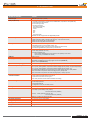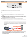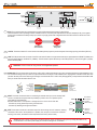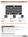
1
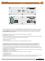
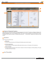
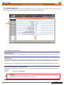
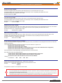
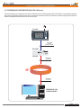
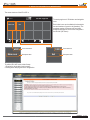
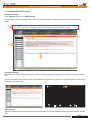
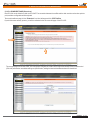
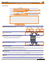
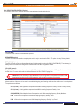
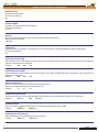
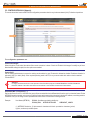
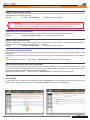
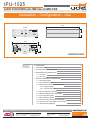
IPU-1025 Audio over IP AUDIO IP DECODER with 25W Class D AMPLIFIER Installation - Configuration - Use 179,5 FRONT IPU-1025 DEVICE ON OK FAULT CALL IN OUT CONFIG NET USB 45,0 ACTIVITY Engineered and made in E.U. SIDE 135,2 TL IPU-1025 INPUT MADE IN SPAIN LAN AUDIO LINK +24VDC DC IN TL 41,2 SPK IPU-1025 REAR INDEX PAGE 1.- DESCRIPTION 2 2.- TECHNICAL DATA 3 4 3.- TYPICAL APPLICATION OF IPU-100 5 5 4.- DESCRIPTION OF CONNECTIONS. 4.1.- Front view. 7 4.2.- Rear view. 5.- DEVICE CONFIGURATION (WEBSERVER). 5.1.- Home page (HOME) 5.2.- SIP Configuration (SIP) 5.3.- Extension SIP Configuration (EXTENSIONS) 5.3.1.- Erasing & editing 5.3.2.- P.A. zones edit page 5.4.- Device configuration (DEVICE) 5.5.- Network configuration LAN. (NETWORK) 5.6.- Time configuration (TIME). 5.7.- Date configuration (DATE). UNION DESARROLLOS ELECTRONICOS Barcelona Avda. BARCELONA, 24 08970 - SANT JOAN DESPÍ BARCELONA - ESPAÑA 5.8.- Password configuration device (PASSWORD). 5.9.- Reset to factory default (RESET TO FACTORY) 8 8 10 13 15 16 22 25 27 27 28 29 5.10.- Remote Reboot (REBOOT) 29 UDE reserves the right to modify the technical characteristics of its products without previous notice Tel: +34 93 477 28 54 Fax: +34 93 261 17 52 [email protected] Madrid C/ LUIS I, 88, 3ª planta 28031 - MADRID ESPAÑA Tel: +34 91 311 60 76 Fax: +34 91 450 19 97 [email protected] PUBLIC ADDRESS Systems Rev. 0 610.440A 1 29 IPU-1025 1.- DESCRIPTION IPU-1025 DEVICE ON OK FAULT CALL IN OUT CONFIG NET USB ACTIVITY Engineered and made in E.U. TL IPU-1025 INPUT MADE IN SPAIN AUDIO LINK LAN +24VDC DC IN TL SPK The public address system for IP networks of UNION DESARROLLOS ELECTRONICOS allows the creation of conventional PA and security systems, allowing us to interconnect with IP devices following SIP standard. Unión Desarrollos Electrónicos Audio offers the IPU-360 SIP server that will centralize and coordinate all communication of IP paging elements ensuring maximum functionality of all of them, with minimal risk. The IPU-1025 has included many functions within the same device: decoder and audio manager. With these functions allow the user to: - Connect to loudspeakers, horns or trumpets directly through the integration of a class D amplifier with a maximum power of 25W. - This amplifier has a low impedance output allows direct connection to PA speakers. - Connect the decoder within an IP network. - Connect an audio source. - Connect a microphone with or without phantom power for simple messaging to the IP network. The IPU-1025 decoder becomes the key element to ensure compatibility with all loudspeakers and horns/trumpets on the PA portfolio of UNION DESARROLLOS ELECTRONICOS, so that you can use to adapt older installations today. Besides concentrating on just one set of IP decoder with built-in amplifier allows savings in space, power and price of the final device. The IP system is suitable for any type of installation: schools, sports centers, industrial areas, department stores, airports, etc ... . It is recommended for remote management applications such as: Remote management of parking, remote management facilities on installation that require sound systems. The IPU-1025 allows encoding and decoding multiple audio formats, such as G-711 and G-722 suitable for Voice and PCM suitable for Background Music environment applications. The IPU-1025 may be operated in two different ways, making it very versatile in any installation: - 24V AC Adaptor (18..30V). - 24V backup battery (18..30V). The IPU-1025 configuration by the technician is done by accessing to the integrated Webserver using a password, but if the user or operator needs to monitor the status of it, then also can be done remotely, just knowing the IP address of the device. Installation - Configuration - Use - IPU-1025 Rev. 0 610.440A 2 29 IPU-1025 2.- TECHNICAL DATA TECHNICAL FEATURES VALUES CPU Principal PIC32 CPU (Microchip™ powered). LAN port (Ethernet) - 10/100Mbit, Full/Half duplex, Autonegociación, AutoMDI/MDI-X, Compatible con PoE (IEE802.3af). - LINK and ACTIVITY leds included.I - RJ-45 socket type (8 pins). - IP protocols supported: IPV4 (IPV6 not supported). DHCP (Auto/Manual). TCP/IP. UDP. RTP. SIP. HTTP, AnnounceIP. The IPU-100 can only process non-fragmented packets. AUDIO LINK port Dedicated port to the connection with the IP Paging Desk (IPU-100P), that includes: - Digital Control Bus: RS485 (115200bps, 8bits, No Parity, 1 stop bit, No flow Control). - Balanced Audio Output (0dB, 0.775mVrms/600Ω). - Balanced Audio Input (0dB, 0.775mVrms/10KΩ). INPUT port Dedicated port to connect to analog input audio devices: - Differential Microphone (2mVrms/600Ω, Phantom 12V). - LINE IN (300mVrms/10KΩ, connection to auxiliary Background Music devices). - Activation through REMOTE IN (Close Contact) or VOX function. SPK port Dedicated port to the connection of loudspeakers, horns or trumpets at low impedance: - Audio Output (25W/8Ω, THD <10%). - Activation of REMOTE OUT. - Close Contact (INCOMING call on-live). Maximum Load capability: 0.5A at 24Vdc. - Open Contact (no INCOMING call received). USB port USB 2.0 Type A. LEDs (only informative) Power ON, LAN Activity (NET ACTIVITY), CONFIG mode, OUTCOMING call (CALL OUT), INCOMING call (CALL IN), Device properly register on SIP server (DEVICE OK), Failure on Device (DEVICE FAULT). System Clock Backup Supply Audio Format (Encoder) 3V Lithium Battery, CR2025 type (Not rechargeable) Outcoming Call to default extension activation REMOTE IN input (switch type). - Close Contact to start and hold the out coming call. - Open Contact to cancel the out coming call. VOX control (Threshold level and Pre/Post activation time settings). Remote Management Using the Webserver built-in in the device the following remote features are available: - Functionality Supervision. - Password Management. - Configuration of : SIP, LAN, Time/Date, Device. Security Level Password system of 8 alphanumeric characters. Power Main: - AC Adaptor (recommended): 24Vdc (IPW-25). 0.9A PPTC internal fuse (resettable). Included Codec: G.711 (u-Law). 8 bits logarithmic compression and 8KHz sampling frequency. Quality: Low (As Factory Default). G.711 (a-Law). 8 bits logarithmic compression and 8KHz sampling frequency. Quality: Low. G.722(ADPCM).8 bits Adaptive Linear Compression and 16KHz sampling frequency. Quality: Medium. PCM. 16 bits without compression and 8KHz sampling frequency. Quality: Good. PCM. 16 bits without compression and 16KHz sampling frequency. Quality: Very Good. - Backup: Battery (external): 24Vdc (18..30V). 0.9A PPTC internal fuse (resettable). Consumption Operation temperature Storage temperature Humidity 32W máx. at 24Vdc. (IPU-100P mode: 38W) Weight 0.6 Kg -5 a +45ºC (0 a +40ºC, recommended) -15 a +60ºC 5% a 95%, witthout condensation Installation - Configuration - Use - IPU-1025 Rev. 0 610.440A 3 29 IPU-1025 3.- TYPICAL APPLICATION OF IPU-100 3. TYPICALAPPLICATION OF IPU-100. Figure 1 provides an example configuration of the PA system for IP networks of UDE. The audio decoder IPU-1025 model is the element that allows the decoding of audio sent digitally to a conventional audio signal to be amplified conveniently and connected directly to speakers, horns or trumpets. The IP Paging Desk (IPU-100P) with color touch screen, where the operator can select the zones where the message must be activated once you press and hold the button of "PTT" (Talk). In addition, the SIP server (IPU-360) which acts as intermediary between all IP devices connected to the LAN working. As can be seen our IPU-1025 devices can connect to the wide range of speakers, horns and trumpets of UNION DESARROLLOS ELECTRONICOS. IPU-100P IPU-1025 USB IPU-100P DEVICE ON ON OK FAULT CALL IN OUT FAULT CONFIG NET USB ACTIVITY Engineered and made in E.U. MESSAGE SPEECH IP IPU-1025 IPU-100 DEVICE ON OK FAULT CALL IN OUT CONFIG NET USB IPU-1025 ACTIVITY Engineered and made in E.U. IPU-100 DEVICE ON OK FAULT CALL IN OUT CONFIG NET USB ACTIVITY Engineered and made in E.U. IPU-1025 DEVICE ON IPU-360 OK FAULT CALL IN OUT CONFIG NET USB ACTIVITY Engineered and made in E.U. Installation - Configuration - Use - IPU-1025 Rev. 0 610.440A 4 29 IPU-1025 4.- DESCRIPTION OF CONNECTIONS 4.1. Front view IPU-1025 DEVICE ON OK CALL IN FAULT CONFIG NET OUT USB 1 ACTIVITY Engineered and made in E.U. 6 7 4 5 3 2 8 1 LED ON. This indicator shows that the equipment is properly powered and that the main application is running. 2 LED NET ACTIVITY. This indicator shows the data activity when is connected to an Ethernet LAN. When you receive IP packets should be the LED blinking. 3 LED CONFIG. This indicator shows that session of configuration (Setup) by Webserver is open. NOTE:This LED appears blinking (orange) while WEBSERVER session is open, although the operator / administrator has finished with maintenance. It is desirable to close the work session when this is over to indicate properly the status and do not allow confusion with front indicators. 4 LED CALL IN. This indicator is set when an incoming call (active decoder mode) is received and accepted, and is active while the call emitter keep the channel open. Once emitter point drop the call, the server of the installation disable the call and the CALL IN indicator will turn off. When the LED remains off indicates that the IPU-1025 is not getting any calls. 5 LED CALL OUT. This indicator is activated when the IPU-1025 device is the generator of a voice call, there are two types of call: Using a IP Paging Desk Controller (IPU-100P) connected to the IPU-1025 reports that the user is performing an outgoing call to one or more areas. So that the LED is turned on the following sequence of events must happen. 1a.The IPU-100P device makes a request to the IPU-1025, to provide an outgoing call to one or more paging zones selected by touch screen and Pressing the PTT button (talk). 2a.The IPU-1025 processes the request and sends the information through the IP network to the server to communicate with selected decoders. The Call Out LED has not yet been activated, communication is not established. 3a.The IPU-360 processes and sends packets with information to the IPU-100 that communication begins feasible. At this time the CALL OUT LED turns ON. 4a.This indication remains active until the user releases the call button. At which the IPU-1025 reports to the installation server the call cancelling and when the cancellation is accepted, then the CALL OUT indication is turned off, releasing all resources used during communication. IPU-360 2a IPU-100P USB IPU-100 IPU-100P ON IPU-100 IP FAULT DEVICE ON MESSAGE OK FAULT CALL IN OUT CONFIG NET USB ACTIVITY SPEECH Engineered and made in E.U. 1a 4a 3a Encoding directly the audio signal connected to INPUT (+/-) of the IPU-1025, the device is able to detect the audio modulation and generate a call to the extension that has been programmed on the Webserver. The IPU-360, Public Address IP manager, will determine the priority and connect the call to the appropriate paging zones. Later will confirm the call to the IPU-1025, audio encoder, which turns on the CALL OUT LED. While audio modulation was present or remote input was active, the IPU-1025 input will be encoded and sent through the IP network showing your work status through the LED CALL OUT. Installation - Configuration - Use - IPU-1025 Rev. 0 610.440A 5 29 IPU-1025 4.- DESCRIPTION OF CONNECTIONS 4.1. Front view IPU-100 DEVICE ON OK FAULT CALL IN OUT CONFIG NET USB 1 ACTIVITY Engineered and made in E.U. 6 6 7 4 5 3 2 8 LED DEVICE OK. The IPU-1025 device that registers with the IPU-360 server correctly and received the authorization to use the IP installation, will remain with the DEVICE OK indicator on. The correct register requires a configuration made on our IPU-100 and another on the IP server. This action must be performed only by authorized service personnel. Remember! If you experience problems with the DEVICE OK, so if it ever turns off sporadically, then it is recommended to contact with your local network administrator (LAN). 7 LED DEVICE FAULT. The public address system for IP networks according to the SIP standard, requires signaling data in order to establish a secure and reliable communication, executed in the initialization of a device to connect to the LAN (LocalArea Network) or periodically to refresh the status of the IPU-360 server. The IPU-1025 automatically executes a registration attempt to the server configured in its settings and every time you restore the power will also run the connection attempt. During the process, the device remains without registration with the IPU-360 server, the DEVICE FAULT LED is RED, indicating that there is a connection problem with the server so the device is not operating temporarily. Along with the lighting there is a error beep signal that emits periodic tones indicating the inoperability of the encoder / decoder (beep sound can be disabled from the Webserver). 8 Connector USB. The device allows the updating of internal management software from the USB terminal. Installation - Configuration - Use - IPU-1025 Rev. 0 610.440A 6 29 IPU-1025 4.- DESCRIPTION OF CONNECTIONS 4.2. Rear view TL IPU-1025 INPUT MADE IN SPAIN 13 LAN AUDIO LINK +24VDC DC IN 24 VDC 14 TL SPK 11 12 9 10 9 DC IN. This connector allows us to power the device using a 24Vdc external power supply ( model: IPW-25). These include that of the 2 powering methods available on the IPU-1025, the power input with the IPW-25 AC adapter (DC IN), is the highest priority input and disables the battery backup input, which only supply power if the voltage delivered in the DC IN terminal is absent or is lower than 18Vdc. PRIORIDAD PRIORIDAD Alimentación 24V estándard Alimentación emergencia 10 +24 VDC. The terminal allows IPU-1025 connection to a battery backup system to prevent the system fails during a primary power failure (IPW-25). 11 LAN. The LAN port allows the connection of the IPU-1025 to the IP network. It supports automatically low speed networks 10-BASET (10Mbits) and improved speed networks 100-Base-TX (100Mbits). The left indicator reports data activity on the LAN (ACTIVITY), while on the right it is properly linked to the LAN (LINK). Attention! The IPU-1025 can only process non-fragmented packets. 12 AUDIO LINK. This connector allows connection of an IPU-100P or allows the expansion and control, of external devices through the digital bus, also has a balanced analog audio input and one output that allow the exchange of audio between the IP Paging Desk Controller and the IPU-1025 (encoder / decoder). We recommend using UTP wiring to connect both devices. The IPU-100P (IP Paging Desk) can be powered via theAUDIO LINK when you are less than 50 meters of the IPU-100. 8 1 13 14 BROWN BROWN-WHITE GREEN BLUE-WHITE BLUE GREEN-WHITE ORANGE ORANGE-WHITE 8 7 6 5 4 3 2 1 STRAIGHT CABLE 568B EIA/TIA-568B EIA/TIA-568B INPUT. This block of terminals allows us connecting an external audio input, be an auxiliary LINE source or an external microphone with the possibility to power it with 12V of phantom power ((activated from the Webserver). Activation when there is a microphone or background music source can be done with: - Activation by closing remote input to the ground terminal. - Activation by detecting audio signal modulation. 8 7 6 5 4 3 2 1 BROWN BROWN-WHITE GREEN BLUE-WHITE BLUE GREEN-WHITE ORANGE ORANGE-WHITE INPUT TL 13 14 SPK. This euroblock connector is the audio output from the incoming call via IP networks, enabling connection of IPU-1025 in low impedance to a speaker, horn, trumpet or a set of these. While the incoming call is active, the remote control output will remain active (closed contact). SPK TL MIC/LINE IN+ MIC/LINE IN0V (GND) TL REMOTE IN (TL) LINE OUT+ LINE OUT0V (GND) TL REMOTE IN (TL) Caution! Avoid to connect on the input or line block terminals, direct connections to the ground (including MIC/LINE and TL). In case the line TL it is used a power supply do not refer it to the ground, use isolation. Installation - Configuration - Use - IPU-1025 Rev. 0 610.440A 7 29 IPU-1025 5.- DEVICE CONFIGURATION (WEBSERVER) 5. DEVICE CONFIGURATION (WEBSERVER). The IPU-1025 configuration is done by accessing to the IP address assigned to the device by the site administrator if you work in Manual mode assignment (Static Mode), or by the DHCP server if you work in automatic mode. Static IP by default is: 192.168.0.210 5.1 HOME PAGE (Home). The HOME page of the IPU-100 WEB application allows everyone access to configuration menus and display the status variables of the encoder / decoder. 5 1 IPU-1025 2 3 4 NOTE: UNION DESARROLLOS ELECTRONICOS reserves the right to modify all or part of WEB server design in order to offer a better product to their customers, which is why we may appear different from pictures provided in this document and results that you can get the product you have purchased. If you have any doubts consult the technical department of UDE . 1 Menú. This area specifies the different web pages with configuration parameters. 2 List of available Menus. This area displays the menu selection icons that the user can select for your device configuration. When the user selects a different menu to the "HOME" (or Main) will be asked to enter a password. If the password is right and match any of the previously stored will then open the desired menu, if not the access will be denied. Attention! Computer security is a crucial aspect in IP networks. Technical staff is recommended not to store the password default on computers where you can access unqualified personnel to modify the settings of IP equipment. Installation - Configuration - Use - IPU-1025 Rev. 0 610.440A 8 29 IPU-1025 5.- DEVICE CONFIGURATION (WEBSERVER) 5 1 IPU-1025 2 3 4 3 Summary of Configuration Parameters. In this area you can check quickly, what are the basic parameters of the device's. Parameters are displayed relative to the Software Application version, the LAN settings (IP, MAC, DNS), the connection parameters to the SIP server (SIP Server IP, data ports, SIP Extension number, SIP authentication password, ...), volume values assigned to the audio inputs and outputs. 4 Status Monitor. In this area you can see three zones: LEDs status. It shows in real time the status (on, off, flashing) of all indicators present on the front panel. Activation signal status. Shows the state of the activation signals of different basic functions such as: VOX activated, MIC activated, etc... Sensor level status. It shows the voltage measurement of the sensors included on the device: 24V Adaptor, 24V Backup Battery, VOX signal level detected, Microphone supply. 5 Area 5: Time and Date. Installation - Configuration - Use - IPU-1025 Rev. 0 610.440A 9 29 IPU-1025 5.- DEVICE CONFIGURATION (WEBSERVER) 5.2 SIP CONFIGURATION (SIP). The configuration page allows you to configure SIP parameters to ensure the connection to the installation server IPU-360 (SIP server). The parameters configured here must be consistent with SIP server parameters of the system. IPU-1025 The configuration parameters are: Enable SIP changes In case the checkbox is checked, the SIP parameters are available to be configured. If not the configuration parameters are blocked. UDE PA system The signaling communication with the server is SIP. Furthermore due to the public address characteristics, the codifiers and decoders requires additional information inside the standardized datagram. Choose ON to use the UDE PAsignaling information. In case of priority or IPU-100P installations, the box must stay in ON option. In case of 100% SIP standard compliance OFF option. SIP Server IPAddress (format: XXX.XXX.XXX.XXX): Defines the IP address where the SIP server host. It is required that the address contains the 12 numbers along with the 3 breakpoints. Example: SIP Server IP: 168.168.0.254 ¡Attention! It is MANDATORY for the correct operation of the IP AUDIO devices of UNION DESARROLLOS ELECTRONICOS that the SIP Server IP address is FIXED address (static type). Installation - Configuration - Use - IPU-1025 Rev. 0 610.440A 10 29 IPU-1025 5.- DEVICE CONFIGURATION (WEBSERVER) Remote Port (format: XXXXX): Define the management TCP port used by the IPU-360 (SIP server) to communicate with our IPU-1025. The standard default value in the device is 05060, you should keep to ensure compatibility with different SIP servers. Remember to always use a configuration with 5 digits. Example: Remote Port: 05060 Local Port (format: XXXXX): Define the management TCP port used by the IPU-1025 to communicate with the IPU-360 (SIP server). The standard default value in the device is 05060, you should keep to ensure compatibility with different SIP servers. Remember to always use a configuration with 5 digits. Example: Local Port: 05060 UDP Remote Port (format: XXXXX): Defines the data transmission UDP port (Voice / INFO) used by the IPU-360 (SIP server) to communicate with the IPU-1025. The standard default value is 00000 (automatic mode), you should keep this value to ensure compatibility with different SIP servers. Remember to always use a configuration with 5 digits. Example: UDP Remote Port: 00000 UDP Local Port (format: XXXXX): Defines the data transmission UDP port (Voice / INFO) used by the IPU-1025 to communicate with the IPU-360 (SIP server) on the installation. The standard default value is 05004 and it is recommended to keep compatibility with different SIP servers. Remember to always use a configuration with 5 digits. Example: UDP Local Port: 05004 Device extension (username) (from 4 to 8 numbers): It is the IPU-1025 SIP identifier for registering to the IPU-360 (SIP server) to be identified as unique equipment in the SIP net, of the public address by IP protocol. In the systems with UDE Audio equipments, the extensions must be contained in a specific rank: Extensions from 1000 to 1999: Decoders Extensions from 2000 to 2999: Audio codifiers Extensions from 3000 to 3999: Music on hold equipments (do not use in other codifiers/decoders configuration) Extensions from 4000 to 4999: IP desk control (with IPU-100P). Choose the extension number depending in which application the IPU-1025 should work. Some extensions ranks have additional features: Codifier extension between 2000 and 2499, do not activate the TM OUT in the decoder. Codifier extension between 2500 and 2999, activate the TM OUT in the decoder. All extensions between 4000 and 4999 will activate the decoder TM OUT. Example: 2536 1589 4001 Local Extension: 1002 Authen. Device Extension (Username): (Max: 8 alphanumeric characters): Defines the user id in the system when it is working in a secure transmission mode. Example: Authen. ID: 12345678 AreaCo_1 This parameter is optional, if not required then leave it blank. Attention! If you have questions about your authenticated user name or password, contact your Network Administrator or technical staff in charge of the IPU-360 configuration (SIP server). Basic Alphanumeric characters are recommended (standard ASCII codes between 32 and 126), excluding special characters or accents to avoid to block the access in case of any network device or the server does not understand these characters. Installation - Configuration - Use - IPU-1025 Rev. 0 610.440A 11 29 IPU-1025 5.- DEVICE CONFIGURATION (WEBSERVER) Authen. Secret (Password): (Max: 8 alphanumeric characters): Defines the user password when it is working in a secure transmission mode. Example: Authen. PASSW.: zX_0!%¿# (No utilizar caracteres especiales) This parameter is required if the parameter "Authenticated ID" is active, otherwise please leave it blank. Display Name (Caller ID Name): (format: XXXX): Default Call (Streaming): (format: XXXX): Define the extension to call forr activating the background music or for the voice message broadcast from a microphone. Valid values for any extension must be between 3000 and 3999. Example: 3400 Default Call (streaming): SIP Receiver Priority Level (Max:01...min:99): (Not use) SIP Streaming Priority Level (Max:01...min:99): If the UDE PA system is active and the IPU-1025 in codifier mode, a priority can be applied and the IPU-360 will manage. This priority should be between 01 (max priority) in consequence will cut other emitters and 99 (lowest priority). These characteristics give tools to program de PA system over IP. If you need more information of the max number of priorities, consult the IPU-360 datasheet. The SIP Streaming Priority Level must be configured with audio sources like MP3 players or Microphones like PZ-40 for Music on hold calls. It is a different priority from the IPU-100P SIP Paging Desk Priority, that only concerns desk control microphones. IPU-100P SIP Paging Desk Priority Level (Max:01...min:99): These characteristics give tools to program de PA system over IP, if the IPU-1025 is linked with an IPU-100P (desk control), a priority desk can be applied. This priority must be between 01 (max priority) in consequence will cut other desk control and 99 (lowest priority). These characteristics give tools to program de PA system over IP. If you need more information of the max number of priorities, consult the IPU-360 datasheet. The IPU-100P SIP Paging Desk Priority Level is setting for IPU-100 linked with IPU-100P, is different from the SIP Streaming Priority for audio sources or microphones. Time to Expire Register (seconds, MAX:7200...min:0060): Register time for SIP server update, recommended time: 3600 seconds. SIP Desk Name (Max: 32 alphanumeric characters): The IPU-100P desk control, has a label identification name in the main screen to identified from other desk control in the installation. Hall Hotel Las Vegas SIP Desk Name: (20 characters including spaces) NOTE: If the IPU-1025 is not linked with an IPU-100P (desk control), this configuration parameter is disabled. Installation - Configuration - Use - IPU-1025 Rev. 0 610.440A 12 29 IPU-1025 5.- DEVICE CONFIGURATION (WEBSERVER) 5.3 EXTENSION SIP CONFIGURATION (ONLY IPU-100P mode). The public address zone configuration with an IPU-100P desk control must be done with a IPU-1025 codifier. It is not possible to make the desk control configuration with the touch screen. The extension web server of the IPU-1025 menu will allow erasing all IPU-100P zone buttons or editing the PAbuttons of the IPU-100P desk control. IPU-100P USB IPU-100P ON FAULT MESSAGE SPEECH UTP Cable Protocol RS-485 + AUDIO IPU-1025 IPU-1025 DEVICE ON OK FAULT CALL IN OUT CONFIG NET USB ACTIVITY IPU-100 UTP Cable IP protocol IP UTP Cable IP protocol ORDENADOR CON CONEXIÓN A RED Installation - Configuration - Use - IPU-1025 Rev. 0 610.440A 13 29 IPU-1025 5.- DEVICE CONFIGURATION (WEBSERVER) The screen structure of the IPU-100P is: 18.12 IPU-100P Paging Desk #002 Main room 1002 The main page have 10 PA buttons and navigation icons. Each button/ zone can be edited with a description text and numbers of zones to call (decoders). The maximum number of PA zones will be a totally broadcast message for all the zones configured in the IPU-360 (SIP server). Exit 1 #002 Main room Zones extensions Description label 1002 Exit Zone extension Description label To edit the IPU-100P zones, exists 2 ways: 1. Erasing the whole desk control memory. 2. Editing zones keeping the zones configuration. Installation - Configuration - Use - IPU-1025 Rev. 0 610.440A 14 29 IPU-1025 5.- DEVICE CONFIGURATION (WEBSERVER) 5.3.1 ERASING & EDITING (Extensions) Extension main page In the “Extension” page click on: NEW DialPLAN With this selection the IPU-100P begin the process to erase all the information in memory. The data structure will be the factory profile. Caution! The erasing process is irreversible; in case of error the memory information cannot be recovered. IPU-1025P Erasing process page Depending on the amount of information saved on memory, the erasing process can spend from 10 seconds to 44 minutes to erase all data. The IPU-100P screen while the erase process is execute will keep out of work for any paging call. Also a deleting data message will be printed to give user information. 18.12 Deleting data. Please Wait IPU-1025P Zone edit page When the erase process has finished, the webpage will be redirected to the zone edit webpage, also the touch screen of the IPU-100P will work. Installation - Configuration - Use - IPU-1025 Rev. 0 610.440A 15 29 IPU-1025 5.- DEVICE CONFIGURATION (WEBSERVER) 5.3.2 P.A. ZONES EDIT PAGE (Extensions). Each IPU-100 can be linked only with one IPU-100P. The connection between the codifier and the desk control must be done point-topoint, and other configuration must be rejected. To access the edit zone page, click on “Extension” icon in the left menu and click : EDIT DialPlan If you did the erase memory process, you will be redirected to the PA zones edit page of the IPU-100P. IPU-1025P The zone edit page has two main areas, one is the general navigation and edition of the buttons that already exist in the desk control (IPU-100P) and another area allows editing one specific button, adding the label and the different extensions that will call. IPU-1025P Installation - Configuration - Use - IPU-1025 Rev. 0 610.440A 16 29 IPU-1025 5.- DEVICE CONFIGURATION (WEBSERVER) EDIT ZONE PAGE 1 2 3 4 5 6 7 1 IPU-100P buttons navigator. Exist 4 different icons to navigate along all the buttons of the touchscreen. First button Move one button back Group ID: 2 Button edition indicator 3 Group nameEach IPU-100P button can show a label to give 4 Extension configuration in a button. 0123456789 0123456789 Extensions ID: Last button #001 of 250 Button more information about the zone to call in that button, the label can have a maximum of 20 alphanumeric letters. Move next button Top number Example of maxim number to edit #001 of 250 Extension Top number 5 Extension configuration To enter the extensions in a button, the configuration must be done one by one extension, that is enter one extension send the information and successively for all the extension to be in one button. Furthermore the decoders extension are in the Rank between 1000 and 1999. To make it more simple is precise to type the last 3 digits of the extension, the first digit (number 1) is automatically processed. 6 Extension cache: The extension are saved in a cache memory waiting to be sent to the IPU-100P (the Rank of the extensions is between 1000 and 1999). For example when extension 1300 (typing 300), and clicking “Add EXTENSION” the new number appears in the extension 7 Validate When all extensions, labels and buttons are ready, click on “Send data”. This action must be done every time one button is edited. Installation - Configuration - Use - IPU-1025 Rev. 0 610.440A 17 29 IPU-1025 5.- DEVICE CONFIGURATION (WEBSERVER) Button configuration example This example contains the configuration of 3 IPU-100P buttons, with this characteristics: 00.00 IPU-100P Paging Desk 1001 Zone 1 #003 #002 Main room Yard 1 #003 #002 1001 Zone 1 Yard Main room BOTTON 1 Button name: Zone 1 Extension to call: 1001 BOTTON 2 Button name: Main room Extension to call: 1002, 1400 BOTTON 3 Button name: Yard Extension to call: 1003, 1004, 1010 Button 1 edition Number of extension to call by the button. Type new label. Click on “Send data”. Button 2 edition Number of extension to call by the button. Type new label. Click on “Send data”. Button 3 edition Number of extension to call by the button. Type new label. Click on “Send data”. ZONE EDIT PAGE IPU-1025P Without any data inside the system, the webpage should look like: - Edition of button 1. - First extension to configure inside the button 1. Installation - Configuration - Use - IPU-1025 Rev. 0 610.440A 18 29 IPU-1025 5.- DEVICE CONFIGURATION (WEBSERVER) BUTTON 1 EDITION 1001 Zone 1 1 2 3 001 1001 4 5 BOTTON 1 EDITION The parameters to configure for button 1: 1. Button 1 label. 2. Extension to call: 001 (equal to 1001). 3. Confirm extension with: Add EXTENSION 4. Extension 1001 appears in the extension box. 5. In button number one has only one extension to call (1001), there is no other extension to configure and configuration must be uploaded. Click on button: Send data. Button 1 configuration has been saved and screen shows the new button. 00.00 IPU-100P Paging Desk 1001 Zona 1 1 Installation - Configuration - Use - IPU-1025 Rev. 0 610.440A 19 29 IPU-1025 5.- DEVICE CONFIGURATION (WEBSERVER) BUTTON 2 EDITION #002 Main room 1 Comedor 2 2B 3 3B 002 1002, 1400 4 4B 5 BUTTON 2 EDITION The parameters to configure for button 2: 1. Button 2 label. 2. Extension to call: 002 (equal to 1002). 3. Confirm extension with: Add EXTENSION 4. Extension 1002 appears in the extension box. 2B. Type the second extension to call in button 2, this is extension 400 (equal to 1400). 3B. Confirm extension with: Add EXTENSION 4B. Extension 1400 appears in the extension box. 5. In button number two has only two extensions to call (1002, 1400), there is no other extension to configure and configuration must be uploaded. Click on button: Send data. Button 2 configuration has been saved and screen shows the new button. 00.00 IPU-100P Paging Desk 1001 Zone 1 #002 Main room 1 Installation - Configuration - Use - IPU-1025 Rev. 0 610.440A 20 29 IPU-1025 5.- DEVICE CONFIGURATION (WEBSERVER) BUTTON 3 EDITION #003 Yard 1 Zona alta 2 2B 2C 3 3B 3C 003 1003, 1004, 1010 4 4B 4C 5 BUTTON 3 EDITION The parameters to configure for button 3: 1. Button 3 label. 2. Extension to call: 003 (equal to 1003). 3. Confirm extension with: Add EXTENSION 4. Extension 1003 appears in the extension box. 2B. Type the second extension to call in button 3, this is extension 004 (equal to 1004). 3B. Confirm extension with: Add EXTENSION 4B. Extension 1004 appears in the extension box. 2C. Type the second extension to call in button 3, this is extension 010 (equal to 1010). 3C. Confirm extension with: Add EXTENSION 4C. Extension 1010 appears in the extension box. 5. In button number three has three extensions to call (1003, 1004 and 1010), there is no other extension to configure and configuration must be uploaded. Click on button: Send data. Button 3 configuration has been saved and screen shows the new button. 00.00 IPU-100P Paging Desk 1001 Zone 1 #002 Main room #003 Yard 1 Installation - Configuration - Use - IPU-1025 Rev. 0 610.440A 21 29 IPU-1025 5.- DEVICE CONFIGURATION (WEBSERVER) 5.4. DEVICE CONFIGURATION. (Device). This section allows you to configure the analog parameters and modes of the device. IPU-1025 IPU-100 Mode. To set the mode of the IPU-1025 between 3 options: SPEAKER (Receiver). The IPU-1025 behaves as audio reception point and is ready to receive calls ONLY. This option is set by Factory default. TREAMING (Emitter). The IPU-1025 will act as an audio emitter point and it will be ready to make calls ONLY (VOICE/MUSIC). The streaming is always done to the extension configured as "Default Call" in the SIP configuration section. . IPU-100P (Normal). The IPU-1025 will act as an audio emitter point (VOICE mode) being synchronized with the IP Paging Desk connected to the AUDIO LINK. For more details refer to the User Manual of the IPU-100P IP Paging Desk. Attention! Do not use the IPU-100P Mode when no IP Paging Desk is connected to the AUDIO LINK terminal as it can lock the IPU-1025 temporarily until you perform a reboot of the device. VoIP Codec. Allows selection of the codec to be used to encode both outgoing and incoming calls when the audio source is a microphone. The options are as follows: G.711 (u-Law). 8 bits logarithmic compression and 8KHz sampling frequency. Quality: Low (As Factory Default). G.711 (a-Law). 8 bits logarithmic compression and 8KHz sampling frequency. Quality: Low. G.722(ADPCM). 8 bits Adaptive Linear Compression and 16KHz sampling frequency. Quality: Medium. PCM. 16 bits without compression and 8KHz sampling frequency. Quality: Good. PCM. 16 bits without compression and 16KHz sampling frequency. Quality: Very Good. Installation - Configuration - Use - IPU-1025 Rev. 0 610.440A 22 29 IPU-1025 5.- DEVICE CONFIGURATION (WEBSERVER) BEEPER function: Activate the acoustic buzzer. OFF (as Factory Default). ON Phantom POWER: Enable the 12V phantom power on MIC input line. OFF (as Factory Default). +12VDC. Audio IN. Select which audio source will be used in "streaming" mode of the two possible ones: MIC Type (as Factory Default). LINE Type. VOX function: Allows the function of "streaming" is activated by the VOX controlled method, activate the equipment to detect an audio signal. OFF (as Factory Default). ON PreVOX time (format: XXX): Select between 000 and 120 seconds, the time it will spend in the detected signal condition before being made the audio "streaming" activation call.Always use a 3-digit format. Example: 000 010 120 PostVOX time (format: XXX): Select between 000 and 120 seconds, the time it will spend in the no-signal condition before being canceled the audio "streaming" call. Always use a 3-digit format. 000 010 120 Example: VOX Level (format: X.X): Selects the minimum threshold for detecting the audio signal as active. Always use a 3-digit format (minimum 1.0V, maximum 3.3V). 1.1 2.7 3.3 Example: Output Volume (format: XXX): Select between 025 and 128, the volume applied to the output which you connect the amplifier.Always use a 3-digit format. 025 (mín.) 080 128 (max.) Example: Output Bass (Gain): Filter can be used to supplement the low frequency response, from +0dB (default set) to +15dB. +0dB (mín.) +15dB (max.) Example: Output Bass (Cut-off Frequency): Filter cut-off frequency for supplement low frequency response. 20Hz (mín.) 150Hz (max.) Example: Installation - Configuration - Use - IPU-1025 Rev. 0 610.440A 23 29 IPU-1025 5.- DEVICE CONFIGURATION (WEBSERVER) Output Treble (Gain): Filter can be used to attenuate/supplement the high frequency response, from -12dB to +10.5dB. -12dB (max. atenuation) +0dB (default) +10.5dB (max. gain) Example: Output Treble (Cut-off Frequency): Filter cut-off frequency for attenuate/supplement high frequency response. 1kHz (mín.) 8kHz (max) Example: MIC IN Volume (format: XXX): Select between 088 and 128, the gain level to be applied to microphone connected to IPU-1025.Always use a 3-digit format. 080 (mín.) 090 128 (max.) Example: LINE IN Volume (format: XXX): Select between 005 and 128, the gain level to be applied to the signal line connected to the IPU-1025. Always use a 3-digit format. 005 (mín.) 050 128 (max.) Example: DESK.MIC IN Volume (format: XXX): Select between 070 and 127, the gain level to be applied to audio from the desk control IPU-100P connected to the IPU-1025. This configuration parameter can only be used in IPU-100P modeAlways use a 3-digit format. 070 (mín.) 090 127 (max.) Example: EXT.MIC IN Volume (format: XXX): Select between 010 and 128, the gain level to be applied to audio from the external microphone of the desk control (IPU-100P) connected to the IPU-1025 (CM-23 is the recommended microphone). This configuration parameter can only be used in IPU-100P mode.Always use a 3-digit format. 010 (mín.) 090 128 (max.) Example: TM OUT Activation Mode: There are few input calls (depending on the extension) that allow the activation of this mode: OFF: ON, voice calls: Any incoming call with the server specifications will activate the TM OUT. ON, all calls: Only incoming calls from desk control (IPU-100P), will activate the TM OUT. SERVER SPECIFICATIONS Codifier extension between 2500 and 2999, activate the TM OUT in the decoder. All extensions between 4000 and 4999 will activate the decoder TM OUT Installation - Configuration - Use - IPU-1025 Rev. 0 610.440A 24 29 IPU-1025 5.- DEVICE CONFIGURATION (WEBSERVER) 5.5 CONFIGURATION LAN. (Network). This section describes how to set NETWORK configuration parameters basic to any local area network (LAN). Follow the steps below. IPU-1025 IPU-100 The configuration parameters are: Enable LAN changes. When this option is unchecked, the status of the current connection is shown. Check the "Enable LAN changes" to modify any of them. Note that after setting this option, the other options are enabled. Enable DHCP. Ask the network administrator to ensure the working mode enabled on your IP network to determine whether IP address allocation is automatic (AUTO) or static (fixed). If the required operating mode is AUTO, then you must enable this mode on the box marked "Enable DHCP". Attention! It is highly recommended for the correct operation of the IP AUDIO equipment of UNION DESARROLLOS ELECTRONICOS that the IP address of each IPU-1025 devices on the network is set to STATIC mode and be a fixed address. Host Name (Max: 15 Characters (1) ): Defines the name of our IPU-1025 within the group of interconnected devices to differentiate it from the rest in a character format. Follow NETBIOS format that enable us to access your device from a web browser without knowing its physical IP address, user being easier to remember since you can assign a name representative of the function or area where it is being serviced. Example: Host Name (NETBIOS): IPU100 (Host Name por defecto de fábrica) IPU100_HALL OFFICE.1STFLOOR CHECKOUT_LANE.3 (1) NETBIOS Restriction: 15 alphanumeric characters with basic punctuation characters (period, hyphen, underscore) and NO spaces. Installation - Configuration - Use - IPU-1025 Rev. 0 610.440A 25 29 IPU-1025 5.- DEVICE CONFIGURATION (WEBSERVER) IP Address (format: XXX.XXX.XXX.XXX): Parameter to set the IP address of the device. It is required that the address contains the 12 numbers along with the 3 breakpoints. A valid example of configuration would be: Example: IP device: 192.168.000.210 (IP Address by Factory default) Attention! If the IP assignment mode is Static or FIXED selected, this IP address should be provided by the Network Administrator. Please contact with him before changing this setting as it can affect the proper functioning of the IP network. SubNet Mask (format: XXX.XXX.XXX.XXX): Defines the subnet mask assigned to your fixed IP. These data should be provided by the Network Administrator. Example: SubNet Mask: 255.255.255.000 (Subnet Mask by Factory default) GateWay (format: XXX.XXX.XXX.XXX): Defines the address of the device on the local area network that allows you to connect to other computers and usually assigned IP address when the system is configured in DHCP mode (or automatic). Example: GateWay: 192.168.000.001 (Gateway IP by Factory default) Primary DNS (format: XXX.XXX.XXX.XXX): Defines the address of the device on the local area network or external that will allow you to connect to other computers in the world through URLs. This address can be not necessary for normal use of your device, then assign it a null address "000.000.000.000" or simply leaves it blank. Example of validAlternative DNS: Primary DNS IP: 192.168.000.001 (Primary DNS IP by Factory default) Alternative DNS o Secondary (format: XXX.XXX.XXX.XXX): Defines the address of the device on the local area network or external that will allow you to connect to other computers in the world through URLs, in case the Primary DNS does not work temporarily. This address can be not necessary for the normal use of your device, then assign a null address "000.000.000.000" or simply leaves it blank. Example of validAlternative DNS: Alternative DNS IP: 000.000.000.000 (Secondary DNS IP by Factory default). Save NETWORK: For the changes to be validated must be pressed the button "Save Network". As these changes modify the essential connection parameters, IPU-1025 must be reset and that is why the "Reboot In Progress" screen is displayed temporary. IPU-1025 IPU-1025 Installation - Configuration - Use - IPU-1025 Rev. 0 610.440A 26 29 IPU-1025 5.- DEVICE CONFIGURATION (WEBSERVER) 5.6 TIME CONFIGURATION. (Time). Select hour, minute and second on the 24h format, and always using 2 digits. Click on "Save TIME" to update the system clock. IPU-1025 Always use the format: (hh/mm/ss) Example: Hour (hh): 22 Minute (mm): 45 Seconds (ss): 55 5.7. DATE CONFIGURATION (Date). Enter the day, month and year desired, considering always use 2 digits format. Click on "Save DATE" to update the system calendar. IPU-1025 Always use the format: (dd/mm/yy) Example: Day (dd): 20 Month (mm): 01 Year (yy): 13 Installation - Configuration - Use - IPU-1025 Rev. 0 610.440A 27 29 IPU-1025 5.- DEVICE CONFIGURATION (WEBSERVER) 5.8 PASSWORD CONFIGURATION DEVICE (Password). The factory login and passwords are: IPU-1025 IPU-100 To change the password first select the desired password type, - operator - admin - supervis then enter the information requested: OLD password: 8 alphanumeric characters withASCII between 32 and 127. NEW password: 8 alphanumeric characters withASCII between 32 and 127. Type again NEW password: 8 alphanumeric characters withASCII between 32 and 127. Confirm password: "Save PASSWORD" Attention! The new password will take effect only if the old password has been entered correctly and has not been wrong to confirm the new password. The system will reset to the new password take effect. Installation - Configuration - Use - IPU-1025 Rev. 0 610.440A 28 29 IPU-1025 5.- DEVICE CONFIGURATION (WEBSERVER) 5.9 RESET TO FACTORY (Reset to Factory) The IPU-1025 can be configured with the factory configuration. IPU-1025 Caution! The erasing process is irreversible; in case of error the memory information cannot be recovered. 5.10 REMOTE REBOOT (Reboot) The IPU-1025 can be remote rebooted just click to the Reboot icon on the left menu and confirm clicking on REBOOT! icon. IPU-1025 IPU-1025 Installation - Configuration - Use - IPU-1025 Rev. 0 610.440A 29 29