1
+LSRW
(OHFWULFDO6DIHW\7HVWHU
0RGHOV
++++
USER MANUAL
:$51,1*
• THIS INSTRUMENT GENERATES AND OUTPUTS A
POTENTIALLY DANGEROUS HIGH VOLTAGE (5kV/6kV).
• BE EXTREMELY CAREFUL WHEN USING THIS
INSTRUMENT.
• BE SURE TO READ THE SAFETY PRECAUTIONS IN
SECTION 3 BEFORE OPERATING.
/LPLWHG:DUUDQW\
The Hipot Safety Testers are warranted to the owner for a period of 1 year
from the date of original purchase against defects in manufacture. This
limited warranty is given by AEMC® Instruments, not by the distributor from
whom it was purchased. This warranty is void if the unit has been tampered
with, abused or if the defect is related to service not performed by AEMC®
Instruments.
For full and detailed warranty coverage, please read the Warranty
Coverage Card, which is attached to the Warranty Registration Card.
Please keep the Warranty Coverage Card with your records.
What AEMC® Instruments Will Do:
If a malfunction occurs within the 1-year period, you may return the
instrument to us for repair or replacement free of charge, provided we have
your REGISTRATION CARD on file. AEMC® Instruments will, at its option,
repair or replace the faulty material.
If a registration card is not on file, we will require a dated proof of purchase,
as well as your REGISTRATION CARD accompanied by the defective
material.
REGISTER ON LINE
www.aemc.com
:DUUDQW\5HSDLUV
What you must do to return an Instrument for Warranty Repair:
First, request a Customer Service Authorization number (CSA#) by phone or
by fax from our Service Department (see address below), then return the
instrument along with the signed CSA Form. Please write the CSA number
on the outside of the shipping container. Return the instrument, postage or
shipment pre-paid to:
Chauvin Arnoux®, Inc. d.b.a. AEMC® Instruments
Service Department
15 Faraday Drive • Dover, NH 03820 USA
Tel:
(800) 945-2362 (Ext. 360)
(603) 749-6434 (Ext. 360)
Fax:
(603) 742-2346 or (603) 749-6309
Caution: To protect yourself against in-transit loss, we recommend you
insure your returned material.
Note: All customers must obtain a CSA# before returning any instrument.
Note: Be sure to keep the original packaging (the box and the inserts)
of your Hipot Tester purchase. You will need it to return the instrument
for it’s yearly calibration.
Hipot Electrical Safety Testers
7DEOHRI&RQWHQWV
Warning ................................................................................................... 3
International Electrical Symbols .............................................................. 3
1. PRODUCT INTRODUCTION .............................................................. 5
1-1. Description ................................................................................. 5
1-2. How to Order.............................................................................. 5
1-3. Front and Rear Panel Features ................................................. 6
1-4. Operational Features ................................................................. 9
2. SPECIFICATIONS............................................................................. 10
3. SAFETY PRECAUTIONS BEFORE OPERATION ........................... 12
3-1. Receiving your Shipment......................................................... 12
3-2. Contents................................................................................... 12
3-3. Safety Notice............................................................................ 12
3-4. Environment............................................................................. 13
4. OPERATION METHOD..................................................................... 14
4-1. Main Display ............................................................................ 14
4-2. Table of Parameters ................................................................ 14
4-3. Preparing the Hipot Tester for Use.......................................... 16
Viewing the Saved Steps:.................................................... 16
Edit/Save the Saved Steps:................................................. 17
Starting a Test: .................................................................... 19
Viewing Utility Functions:..................................................... 21
Edit/Save Utility Functions:.................................................. 23
4-4. Structure of Stored Tests : Steps ............................................ 24
4-5. Menu Parameter Setup............................................................ 25
AC/DC Withstanding Voltage Test (VAC/VDC):.................. 25
Continuous AC/DC Withstanding Voltage Test ................... 26
Insulation Resistance Test (IR) ........................................... 27
Continuity Check (CNT)....................................................... 28
Functions of the Remote Interface: ..................................... 29
5. MAINTENANCE ................................................................................ 31
5-1. Fuse Rating and Type ............................................................. 31
5-2. Cleaning................................................................................... 31
Repair and Calibration........................................................................... 32
Technical and Sales Assistance............................................................ 32
2
Hipot Electrical Safety Testers
:DUQLQJ
• THIS INSTRUMENT GENERATES AND DELIVERS A
POTENTIALLY DANGEROUS HIGH VOLTAGE (5kV).
• BE EXTREMELY CAREFUL WHEN USING THIS
INSTRUMENT.
• BE SURE TO READ THE PRECAUTIONS IN SECTION
3 BEFORE OPERATING.
These safety warnings are provided to ensure the safety of
personnel and proper operation of the instrument.
• Read the instruction manual completely and follow all safety
information before attempting to use or service this instrument.
• This instrument MUST be grounded before use.
• Only qualified personnel should use these testers.
,QWHUQDWLRQDO(OHFWULFDO6\PEROV
This symbol signifies CAUTION! and requests that the user
refer to the user manual before using the instrument.
High voltage; risk of electric shock. The voltage at the
parts marked with this symbol may be dangerous.
Protective Conductor Terminal
Ground (Earth) Terminal
3
Hipot Electrical Safety Testers
FOR THE UNITED KINGDOM ONLY:
The wires in this lead are colored in accordance with the
following code:
E
Green/Yellow:
Earth (Ground)
Blue:
Neutral
L
N
Brown:
Live (Phase)
As the colors of the wires in the power cord may not correspond
with the color markings identified in your plug/appliance, proceed
as follows:
The Green & Yellow wire must be connected to the Earth
terminal marked with the letter E or by the earth symbol
or
colored Green or Green & Yellow.
The Blue wire must be connected to the terminal which is
marked with the letter N or colored Blue or Black.
The Brown wire must be connected to the terminal marked with
the letter L or P or colored Brown or Red.
If in doubt, consult the instructions provided with the equipment
or contact the supplier.
A suitably rated and approved HBC power line fuse should
protect this cable/appliance: refer to the rating information on the
equipment and/or user instructions for details. As a guide, cable
2
of 0.75mm should be protected by a 3A or 5A fuse. Larger
conductors would normally require 13A types, depending on the
connection method used.
• Use caution on any apparatus: potentially high voltages and
currents may be present and pose a shock hazard.
• Safety is the responsibility of the user.
• Always inspect the instrument and test cables prior to use.
Replace defective parts immediately with factory replacement
parts only.
4
Hipot Electrical Safety Testers
352'8&7,1752'8&7,21
'HVFULSWLRQ
®
The AEMC Hipot Testers are designed for AC/DC Withstanding
Voltage Testing and Insulation Resistance Testing (IR),
providing a safe and accurate test environment for the operator.
See section 1-4 for features to ensure a safe operation of high
voltage testing and to protect the user from hazardous shock.
®
AEMC Electrical Safety Testers comply with the requirement of
the electrical equipment & appliance testing standard, UL, CSA,
and other international standards. The testers can be used for
withstanding voltage tests of the various types of electrical and
equipment and components.
The testers include AC withstanding voltage test,
withstanding voltage test and insulation resistance test.
Model
H110
H115
H210
H215
AC (5kV)
DC (6kV)
IR
DC
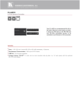
+RZWR2UGHU
AC Hipot Tester, Model H110 ......................................... #2117.81
AC Hipot / IR Tester, Model H115 .................................. #2117.82
AC/DC Hipot Tester, Model H210................................... #2117.83
AC/DC Hipot / IR Tester, Model H215 ............................ #2117.84
All models include the tester, lead set with test probe, US power
cord, 1 fuse (2A, 250V), and user manual.
Accessories:
HV Test Pistol, Model SP02............................................ #2117.88
HV Test Lead (3m) 9ft. unterminated at one end ........... #2117.89
Fuse (set of 5) 4A, 250V ................................................. #2117.90
Fuse (set of 5) 2A, 250V ................................................. #2117.92
5
Hipot Electrical Safety Testers
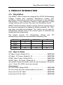
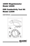
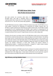
)URQWDQG5HDU3DQHO)HDWXUHV
2
4
3
5
6
7
8
9
®
INSTRUMENTS
FAIL
CAUTION
HIGH VOLTAGE
!
5.0 kV AC MAX
6.0 kV DC MAX
1
PASS
! TEST
STOP /RESET
MENU
FIELD
EDIT/SAVE
POWER
I
O
10
CONTINUITY
RETURN
19
20
UTILITY
11
12
13
14
15
16
17 18
21
120
100
22
6
23
24
Hipot Electrical Safety Testers
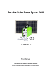
1) PASS Indicator LED - The Green LED indicates test
passage.
2) FAIL Indicator LED - The Red LED indicates test failure.
3) Model number and description.
4) Main Display LCD - The LCD displays all messages, setup
conditions and test results.
5) Left Arrow Key - Press the arrow key to select the setting.
Adjustment is then made with the rotary knob.
6) FIELD Key - When in the “EDIT” mode, the FIELD key will
scroll through the function parameters.
7) Right Arrow Key - Press the arrow key to select the setting.
The adjustment is then made with the rotary knob.
8) CAUTION Indicator LED - During testing the Red LED above
the high voltage output will flash to indicate that dangerous
voltage is present.
9) High Voltage Output Plug - High voltage output terminal.
10) Power Switch - Press to turn the tester on and off.
11) TEST Button - Press the green button to start a test
procedure.
12) STOP/RESET Button - Press the red button to reset/stop a
test procedure.
13) MENU Key - When you press the MENU key, the “MENU”
mode becomes active and you can select setup functions.
14) UTILITY Key - When you press the UTILITY key, the
“UTILITY” mode is active and you can view all the utility
setups.
15) EDIT/SAVE Key - When you press the EDIT/SAVE key, the
“EDIT” mode is active and you can edit the current step or
setup. Press the EDIT/SAVE key again will save this step or
setup.
7
Hipot Electrical Safety Testers
16) Rotary Knob - If the “EDIT” mode is active, turn the knob to
increase or decrease the value of the active parameter. If the
“MENU” mode is active, turn the knob to increase or
decrease the active Step.
17) LCD Backlight Adjustment - Screwdriver adjustment for the
LED backlight (use a small, insulated screwdriver).
18) Buzzer Volume Adjustment - Screwdriver adjustment for the
buzzer volume (use a small, insulated screwdriver).
19) CONTINUITY Terminal - Continuity check output terminal.
20) RETURN Terminal - Test return terminal.
21) Remote Interface - The remote interface facilitates all of the
functions via PLC control.
22) Ground Terminal - Connect Ground terminal to the earth
ground.
23) Fuse Holder with Voltage Selector - To change AC source
voltage, pull the fuse holder and rotate it to the proper value.
(select fuse accordingly).
24) AC Plug - Accepts standard AC power line cords.
8
Hipot Electrical Safety Testers
2SHUDWLRQDO)HDWXUHV
The HiPot Testers offer several additional features:
1) No load setup of trip current and output voltage.
A safe way to setup trip current and output voltage without
having the high voltage activated, or the use of a load
resistor.
2) A large 24 x 2 character LCD with adjustable backlight.
Provides a clear display of all test parameters, including test,
step, mode, status, output voltage, trip current and test time.
3) Quick and easy setup from the front panel.
A user-friendly interface provides a quick and easy way to
set all parameters.
4) Electronic ramping and testing.
Digitally controlled ramping and test time.
5) Line and load regulation.
Linear amplifier and feedback-control maintains the output
voltage independently from load variations.
6) Selectable output frequency.
50/60Hz operation is selectable through the “UTILITY” setup.
7) Adjustable ARC detect level.
ARC detect level can be programmed in the “UTILITY” setup.
8) Storage of up to 6 tests, 6 steps for each test.
6 tests with 6 steps each provides the user with a choice for
testing different types of products.
9) Adjustable output voltage during test.
A special test mode in step 0 allows the user the ability to
manually adjust the output voltage during test.
10) Flashing high voltage indicator.
A flashing red LED warns that high voltage is present at the
output.
11) PLC remote control.
The 9-pin interface provides: inputs: START, RESET
outputs: TEST, PASS, FAIL
12) Data lock function.
Front panel can be locked or unlocked by the “UTILITY”
setup to prevent unauthorized changes to the setup.
9
Hipot Electrical Safety Testers
63(&,),&$7,216(15°C - 35°C ≤ 75% RH)
AC Hi-Pot Specifications (H110 / H115 / H210 / H215)
AC Voltage Range
100V to 5000V (5kV)
Voltage Step
5V/step
Voltage Regulation
1% of reading ± 5 counts
Voltage Accuracy
1% of reading ± 5 counts
(above 500V)
Max Current
20mA @ 5kVAC
Current Limit
0.10 to 20mA, 0.01mA/step
Current Accuracy
1% of reading ± 5 counts
DC Hi-Pot Specifications (H210 / H215)
DC Voltage Range
100V to 6000V (6kV)
Voltage Step
5V/step
Voltage Regulation
1% of reading ± 5 counts
Voltage Accuracy
1% of reading ± 5 counts
(above 500V)
Max Current
7.5mA @ 6kVDC
Current Limit
0.10 to 7.5mA, 0.01mA/step
Current Accuracy
1% of reading ± 5 counts
Insulation Resistance Specifications (H115 / H215)
DC Voltage
500V or 1000V
Resistance Range
1 to 9999MΩ
Resistance Accuracy
1 to 500MΩ: 5% of reading
501 to 2000MΩ: 10% of reading
Note: These instruments are not designed for continuous use at
the maximum rating. The test procedure will automatically stop
when temperature overload is detected.
10
Hipot Electrical Safety Testers
Continuity Check Specifications:
Test Current: 100mA (0.1A)
Current Accuracy: ± 10%
Detect Accuracy: 0.1Ω @ 1Ω
ARC Detect:
Detect Current: 1 to 20mA (1mA step)
Storage:
6 tests; 6 steps per test
Remote Interface:
Type of Terminal: 9-pin D-sub connector
Output Breakdown Voltage: ± 350V
Continuous Load Current: ± 100mA
General:
120VAC Power Source: 100V, 220V, 230V ±10% 50/60Hz
(selectable on the back panel)
Operation Environment:
Indoor use: altitude up to 2000m.
Ambient temperature: 32° to 104°F (0° to 40°C)
Relative humidity: 80% max.
Installation category II
Pollution degree 2
Storage Temperature & Humidity:
14° to 158°F (-10°C to 70°C), 70% RH max.
Dimensions: 17.56”(L) × 12.99”(W) × 5.87”(H)
446mm × 330mm × 149mm
Weight: Approx. 26.5 lbs.(12 kgs)
11
Hipot Electrical Safety Testers
6$)(7<35(&$87,216%()25(23(5$7,21
5HFHLYLQJ\RXU6KLSPHQW
Upon receiving your shipment, be sure that the contents are
correct. Notify your distributor of any missing items. If the
equipment appears to be damaged, file a claim immediately with
the carrier and notify your distributor at once, giving a detailed
description of any damage.
&RQWHQWV
Each Hipot Tester is shipped with 1 high voltage probe, 1 return
lead with retainer, a US AC 110V power cord, a user manual and
product warranty registration card, and an extra fuse for 220V+
supply.
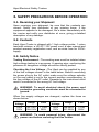
6DIHW\1RWLFH
Testing Environment - The working area must be isolated when
high voltage testing is in progress. A warning sign, cautioning the
presence of dangerous voltage should be clearly posted.
Checking the Line Voltage - The Hipot can be supplied by any
of the line voltages shown in the table below. Before connecting
the power plug to the AC outlet, make sure the voltage selector
on the rear panel is set to the correct position corresponding to
the line voltage of the AC outlet. Damage to the instrument could
result if connected to the wrong AC line voltage.
WARNING. To avoid electrical shock, the power cord
protective grounding conductor must be connected to
ground.
When line supply voltages are changed, replace the fuses as
shown below:
Line
Line
Range
Fuse
Range
Fuse
Voltage
Voltage
100V
90-110V
T 4.0A
220V
198-242V
T 2.0A
120V
108-132V
250V
230V
207-250V
250V
WARNING. To avoid personal injury, disconnect the
power cord before removing the fuse holder.
12
Hipot Electrical Safety Testers
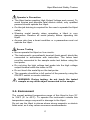
Operator’s Precaution
• The Hipot tester supplies High Output Voltage and current. To
avoid injuries and possible fatal electric shock, only qualified
persons should operate the Hipot.
• On-the-job training is required for the user to operate the Hipot
safely.
• Wearing metal jewelry when operating a Hipot is very
dangerous. Remove all metal jewelry before operating the
Hipot.
• Anyone who has a heart condition or a pacemaker must not
operate the Hipot.
Secure Testing
• Never operate the Hipot on live circuits.
• The instrument’s ground/earth terminal (back panel) should be
connected in accordance with instruction. The return lead
must be connected to the sample under test before using the
test probe.
• Do not plug the high voltage test probe into the high voltage
output terminal while the tester is ON.
• Do not touch the metal tip on the test probe.
• The operator should be in full control of the power by using the
ON/OFF switch or remote interface.
WARNING: During testing, do not touch the tested
sample or any other object connected to the sample.
(QYLURQPHQW
The normal ambient temperature range of this Hipot is from 32°
to 104°F (0° to 40°C). To operate the instrument outside this
temperature range may result in damage to the Hipot.
Do not use the Hipot in places where strong magnetic or electric
fields exist, as it may cause erroneous measurements.
13
Hipot Electrical Safety Testers
23(5$7,210(7+2'
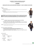
0DLQ'LVSOD\
Storage
Mode
Output Voltage/Current
ARC
Status
1 : 1 VA C V = 5 . 0 0 0 k V * M E N U
Ima x = 0 1 . 0 0 m A
T E S T 0 3 0 . 0 s
Trip Current Limit
Ramp/Test Time
(Actual settings may differ at power-up)
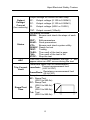
7DEOHRI3DUDPHWHUV
Test: Step
Up to 6 tests can be stored; each test may include up to 6
steps.
Storage
The first number indicates the test number while the
second number indicates the step.
Ex. 3:1 means that the 1st Step in test number 3 is active.
The functions include:
VAC: AC Withstanding voltage test
VDC: DC Withstanding voltage test
Mode
IR:
Insulation Resistance test
CNT: Continuity check
The total available functions will change for different
models.
14
Hipot Electrical Safety Testers
Output voltage or current for each step
AC:
Output
Voltage/
DC:
Current
(for continuity) IR:
CNT:
Status
ARC
Trip Current
Limit
Ramp/Test
Time
Output voltage (0.100 to 5.000kV)
Output voltage (0.100 to 6.000kV)
Output voltage (500V or 1000V)
Output current (100mA)
The status includes:
MENU: Browse and check the steps of each
test
EDIT:
Edit parameters
SAVE: Save parameters
UTIL:
Browse and check system utility
READY: Ready for test
TEST: Testing
PASS: The result of the test is pass
FAIL:
The result of the test is fail
STOP: Stop the test
If the ARC function is enabled, the sign “ ” will
appear when an ARC occurs during the test.
Lower and upper limit of measurement
Current measurement limit
Imax/Imin:
(VAC & VDC)
Resistance measurement limit
Rmax/Rmin:
(IR & CNT)
Ramp time and test time
AC: Ramp/Test
(000.0 to 999.9s)
DC: Ramp/Test
voltage
(000.0 to 999.9s)
IR: Test
(000.0 to 999.9s)
Cnt: Test
ramp
test time
(000.0 to 999.9s)
*
15
Hipot Electrical Safety Testers
3UHSDULQJWKH+LSRW7HVWHUIRU8VH
Viewing the Saved Steps:
1. Press the MENU key to enter the “MENU” mode.
0(18
MENU
2. Use the rotary knob to select the test number.
(1:1, 2:1, 3:1 … 0:0)
9$&
The field selected
is underlined
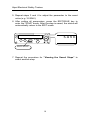
3. Use the right arrow key to select the step. Use the rotary knob
to change the active step. (1:1, 1:2, 1:3 … 1:6)
9$&
The field selected
is underlined
16
Hipot Electrical Safety Testers
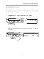
Edit/Save the Saved Steps:
1. Follow the preceding procedure for “Viewing the Saved
Steps“ to select a step.
2. Press the EDIT/SAVE key to enter status EDIT.
(',7
EDIT/SAVE
3. Use the rotary knob to adjust parameter.
9$
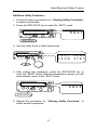
4. Use the FIELD key to change active parameter. Use the arrow
keys to change the setting in the field. Adjust the underlined
field with the rotary knob.
'
N9
FIELD
17
Hipot Electrical Safety Testers
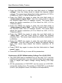
5. Repeat steps 3 and 4 to adjust the parameter to the exact
value (e.g. 3.250kV).
6. After setting all parameters, press the EDIT/SAVE key to
enter the “SAVE” mode. After the step is saved, the status will
automatically return to the EDIT mode.
6$9(
EDIT/SAVE
7. Repeat the procedure for “Viewing the Saved Steps” to
select another step.
18
Hipot Electrical Safety Testers
Starting a Test:
1. Repeat the procedure for “Viewing the Saved Steps” to
select a test (or step).
2. Press the STOP/RESET button to enter the “READY” mode.
5($'<
STOP/RESET
3. Make sure the test environment is safe.
4. Press the TEST button to start the test. When in the “TEST”
mode, the CAUTION LED will flash.
7(67
TEST
5. If you press the STOP/RESET button, the test will stop
6723
STOP/RESET
19
Hipot Electrical Safety Testers
6. If the result of the test is good, the Green PASS LED will light.
3$66
7. If the result of the test is bad, the Red FAIL LED will light and
the buzzer will alert the operator. To stop the alarm, press the
STOP/RESET button again.
)$,/
STOP/RESET
8. Use the rotary knob to view the result of the group step by
step.
20
Hipot Electrical Safety Testers
Viewing Utility Functions:
The utility function enables the user to program the start-up step
in each test, as well as custom modes or features described in
the table on the next page.
1. Press the UTILITY key to enter the “UTIL” mode.
87,/
UTILITY
2. Use the rotary knob or arrow keys to change the active
parameter.
%$% # $%!
21
Hipot Electrical Safety Testers
3. Table of utility functions:
To change the display option under a given mode, press EDIT
and rotate the knob. Press SAVE to store the option.
Parameter
TEST MODE
Option
Description
From
STEP 1
The test mode procedure always begins
from step 1 to the end of the group.
e.g. 3:1 - 3:6, 4:1 - 4:6
The test mode procedure always begins
From the with the selected step to the end of the
present step group.
e.g. 3:3 - 3:6, 4:3 - 4:6
DISABLE
ARC MODE
Disables the ARC detection function.
ENABLE & Enables ARC detection and stops the
STOP
test when ARC is detected.
ENABLE & Enables ARC detection and continues
CONTINUE the test when the arc is detected.
Sets the current level of ARC detection.
(1 to 20mA)
ARC CURRENT
AC (TEST)
FREQUENCY
TEST
CONTROL
MODE
50Hz
Sets AC Hipot output frequency to 50Hz.
60Hz
Sets AC Hipot output frequency to 60Hz.
MODE 1
Control mode from the front panel.
Mode 1: Reset first (recommended)
(press RESET button before test)
MODE 2
Mode 2: Press START button directly.
MODE 3
Mode 3: REMOTE I/O is enabled.
(the start button is disabled)
MODE 4
Mode 4: Reserved.
UNLOCKED
DATA LOCK
CONT.
CALIBRATION
LOCKED
Accepts and saves all parameters from
the test/step and utility.
Locks out any changes to parameters
from the test/step and utility until
unlocked.
Calibrates the short circuit resistance of
test leads for test of continuity check.
22
Hipot Electrical Safety Testers
Edit/Save Utility Functions:
1. Follow the above procedure for “Viewing Utility Functions”
to select a parameter.
2. Press the EDIT/SAVE key to enter the “EDIT” mode.
(',7
EDIT/SAVE
3. Use the rotary knob to adjust parameter.
%$% # $%!
4. After setting this parameter, press the EDIT/SAVE key to
enter the “SAVE” mode. After the parameter is saved, you will
automatically return to the “EDIT” mode.
6$9(
EDIT/SAVE
5. Repeat the procedure for “Viewing Utility Functions” to
select another parameter.
23
Hipot Electrical Safety Testers
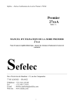
6WUXFWXUHRI6WRUHG7HVWV6WHSV
You can store a total of 6 tests with up to 6 steps per test. In
addition to these six steps, there is an additional step, “0:0” for
special testing. The presentation of stored steps is Test:Step.
The first number represents the test, while the second
represents the step as shown in the chart below.
Step 1
Test
Test
Test
Test
Test
Test
Group 1 Group 2 Group 3 Group 4 Group 5 Group 6
0:0
1:1
2:1
3:1
4:1
5:1
6:1
Step 2
1:2
2:2
3:2
4:2
5:2
6:2
Step 3
1:3
2:3
3:3
4:3
5:3
6:3
Step 4
1:4
2:4
3:4
4:4
5:4
6:4
Step 5
1:5
2:5
3:5
4:5
5:5
6:5
Step 6
1:6
2:6
3:6
4:6
5:6
6:6
The special test step “0:0” contains two types of tests: CAC
(continuous AC output) and CDC (continuous DC output). The
function of CAC or CDC as the same as VAC or VDC, except
that the user can manually adjust the output voltage during the
tests (10V per step).
The ramp may be set, as well as the trip settings, however, the
test will run until manually stopped or if a fault occurs.
24
Hipot Electrical Safety Testers
0HQX3DUDPHWHU6HWXS
AC/DC Withstanding Voltage Test (VAC/VDC):
• Press the MENU key to enter the “MENU” mode, then use the
rotary knob and arrow keys to select a step.
• Press the EDIT/SAVE key to enter the “EDIT” mode. The
cursor enters the “test mode” field. Use the rotary knob to
select mode VAC or VDC.
Functions of FIELD key:
Test mode
VAC (VDC)
Output voltage
V=X.XXXkV
Measurement upper limit
Imax=XX.XxmA
Measurement lower limit
Imin=XX.XxmA
Ramp time
RAMP=X.XXXs
Test time
TEST=X.XXXs
25
Hipot Electrical Safety Testers
• Press the FIELD key to edit the next field which is “output
voltage”. Use the rotary knob to adjust the desired output
voltage. The arrow keys adjust the knob’s resolution (0.100 to
5.000kV for VAC, 0.100 to 6.000kV for VDC).
• Press the FIELD key again to enter the next field which is
“measurement upper limit”. Use the rotary knob to adjust
the desired upper limit of leakage current. The arrow keys
adjust the knob’s resolution (0.10 to 20mA for VAC, 0.10 to
7.5mA for VDC).
• Press the FIELD key again to enter the next field which is
“measurement lower limit”. Use the rotary knob to adjust
the desired lower limit of leakage current. The arrow keys
adjust the knob’s resolution (0.10 to 20mA for VAC, 0.10 to
7.5mA for VDC).
• Press the FIELD key again to enter the next field which is
“ramp time”. Use the rotary knob to adjust the desired
ramping time. The arrow keys adjust the knob’s resolution (0
to 999.9s).
• Press the FIELD key again to enter the next field which is
“test time”. Use the rotary knob to adjust the desired testing
time. The arrow keys adjust the knob’s resolution (0 to
999.9s).
• Press FIELD key again to return the first field which is “test
mode” again.
• Press EDIT/SAVE key to save all the parameters.
Continuous AC/DC Withstanding Voltage Test (CAC/CDC)
• The CAC/CDC test is available only on the step “0:0”. Like the
traditional hi-pot tester, you can use the rotary knob and arrow
keys to adjust the output voltage during testing (10V step
max.).
• All the parameters of CAC/CDC are the same as VAC/VDC,
except the testing time. The testing of CAC/CDC is not limited
(even if you program a time, the ramp is still adjustable).
26
Hipot Electrical Safety Testers
Insulation Resistance Test (IR)
• Press the MENU key to enter the “MENU” mode, then use the
rotary knob and arrow keys to select a step.
• Press the EDIT/SAVE key to enter the “EDIT” mode. The
cursor enters the “test mode” field. Use the rotary knob to
select the “IR” mode.
Functions of FIELD key:
Test mode
IR
Output voltage
V=X.XXXkV
Measurement upper limit
Rmax=XXXXMΩ
Measurement lower limit
Rmin=XXXXMΩ
Test time
TEST=X.XXXs
• Press the FIELD key to edit the next field which is “output
voltage”. Use the rotary knob to adjust the desired output
voltage to 500V or 1000V.
• Press the FIELD key again to enter the next field which is
“measurement upper limit”. Use the rotary knob to adjust
the desired upper limit of resistance. The arrow keys adjust
the knob’s resolution (0 to 9999MΩ).
• Press the FIELD key again to enter the next field which is
“measurement lower limit”. Use the rotary knob to adjust
the desired lower limit of resistance. The arrow keys adjust the
knob’s resolution (0 to 9999MΩ).
• Press the FIELD key again to enter the next field which is
“test time”. Use the rotary knob to adjust the desired testing
time. The arrow keys adjust the knob’s resolution (0 to
999.9s).
27
Hipot Electrical Safety Testers
• Press the FIELD key again to return the first field which is
“test mode”.
• Press the EDIT/SAVE key to save all the parameters.
• When Rmin=0 or Rmax=0 it only appears measurement value
without making value limit judgment.
Continuity Check (CNT)
• Press the MENU key to enter the “MENU” mode, then use the
rotary knob and arrow keys to select a step.
• Press the EDIT/SAVE key to enter the “EDIT” mode. The
cursor enters the “test mode” field. Use the rotary knob to
select mode CNT. The output current is fixed to 0.100A.
Functions of FIELD key:
Test mode
CNT
Measurement upper limit
Rmax=XXXXΩ
Testing time
TEST=X.XXXs
• Press the FIELD key to enter the next field which is
“measurement upper limit”. Use the rotary knob to adjust
the desired upper limit of resistance. The arrow keys adjust
the knob’s resolution (0 to 1.200Ω).
• Press the FIELD key again to enter the next field which is
“test time”. Use the rotary knob to adjust the desired testing
time. The arrow keys adjust the knob’s resolution (0 to
999.9s).
• Press FIELD key again to return the first field which is “test
mode”.
• Press the EDIT/SAVE key to save all the parameters.
28
Hipot Electrical Safety Testers
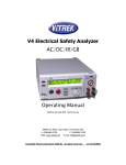
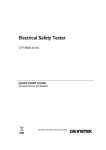
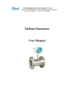
Functions of the Remote Interface:
The remote interface provides two inputs (START and RESET)
and three outputs (TESTING, PASS and FAIL).
COMMON
START
RESET
PASS 1
PASS 2
TESTING 1
TESTING 2
FAIL 2
FAIL 1
RESET:
Connecting “RESET” (pin 1) to “COMMON” (pin 3)
will reset the tester (provides the same functionality
as the RESET button on the front panel).
START:
In status READY mode, connecting “TESTING” (pin
2) to “COMMON” (pin 3) will start the test (provides
the same functionality as the TEST button on the
front panel).
TESTING 1,
TESTING 2: During test, the “TESTING 1” (pin 4) and TESTING
2” (pin 5) output pins will be shorted.
PASS 1,
PASS 2:
FAIL 1,
FAIL 2:
If the test passed, the “PASS 1” (pin 6) and
“PASS 2” (pin 7) output pins will be shorted.
If the test failed, the “FAIL 1” (pin 8) and “FAIL 2”
(pin 9) output pins will be shorted.
29
Hipot Electrical Safety Testers
REMOTE
CONTROLLER
RESET
(pin 1)
START
(pin 2)
COMMON
(pin 3)
TESTING1
(pin 4)
TESTING2
(pin 5)
PASS1
(pin 6)
PASS2
(pin 7)
FAIL1
(pin 8)
FAIL2
(pin 9)
TESTER
REMOTE
INTERFACE
The function keys on the front panel are disabled when any two
pins on the rear panel for Reset, Start or Common mode
shorted.
Please check the remote control device.
30
Hipot Electrical Safety Testers
0$,17(1$1&(
The following instructions are for qualified persons only.
To avoid electrical shock, do not perform any service other than
the operating instructions contained in this manual, unless you
are qualified to do so.
Use original replacement parts only.
)XVH5DWLQJDQG7\SH
If the fuse blows, the product will not operate. Try to determine
and correct the cause of the blown fuse, then replace the fuse
with correct rating and type shown as below:
Line
Voltage
Range
Fuse
Line
Voltage
Range
Fuse
100V
120V
90-110V
108-132V
T 4.0A
250V
220V
230V
198-242V
207-250V
T 2.0A
250V
WARNING: Replace only with 250V fuse of the
specified type and rating. Disconnect the power
cord before replacing the fuse.
&OHDQLQJ
• To keep the instrument clean, wipe the case with a damp cloth
and detergent.
• Do not use abrasives or solvents.
• Do not permit liquids or foreign matter to enter the Hipot.
31
Hipot Electrical Safety Testers
5HSDLUDQG&DOLEUDWLRQ
To ensure that your instrument meets factory specifications, we recommend
that it be submitted to our factory Service Center at one-year intervals for
recalibration, or as required by other standards or internal procedures.
For instrument repair and calibration:
You must contact our Service Center for a Customer Service Authorization
number (CSA#). This will ensure that when your instrument arrives, it will be
tracked and processed promptly. Please write the CSA number on the
outside of the shipping container. If the instrument is returned for calibration,
we need to know if you want a standard calibration, or a calibration traceable
to N.I.S.T. (Includes Calibration Certificate plus recorded calibration data).
Chauvin Arnoux®, Inc.
d.b.a. AEMC® Instruments
15 Faraday Drive
Dover, NH 03820 USA
Tel:
(800) 945-2362 (Ext. 360)
(603) 749-6434 (Ext. 360)
Fax:
(603) 742-2346 or (603) 749-6309
(Or contact your authorized distributor)
Costs for repair, standard calibration, and calibration traceable to N.I.S.T. are
available.
Note: All customers must obtain a CSA# before returning any
instrument.
7HFKQLFDODQG6DOHV$VVLVWDQFH
If you are experiencing any technical problems, or require any assistance
with the proper operation or application of your instrument, please call, mail,
fax or e-mail our technical support hotline:
Chauvin Arnoux®, Inc.
d.b.a. AEMC® Instruments
200 Foxborough Boulevard
Foxborough, MA 02035, USA
Phone: (800) 343-1391
(508) 698-2115
Fax:
(508) 698-2118
www.aemc.com
Note: Do not ship Instruments to our Foxborough, MA address.
32
®
®
Chauvin Arnoux , Inc. d.b.a AEMC Instruments
15 Faraday Drive • Dover, NH 03820, USA
www.aemc.com
99-MAN 100227 v2-02/02