1
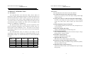
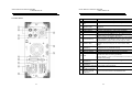
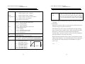
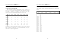
ELECTRICAL SAFETY TESTER
USER MANUAL
ELECTRICAL SAFETY TESTER
USER MANUAL
EC Declaration of Conformity
We
GOOD WILL INSTRUMENT CO., LTD.
WARNING
No. 7-1, Jhongsing Rd., Tucheng City, Taipei County 236, Taiwan.
MANUFACTURER ASSUMES NO LIABILITY
IF UNIT OPERATED IN AN UNSAFE MANNER
GOOD WILL INSTRUMENT (SUZHOU) CO., LTD.
No. 69 Lushan Road, Suzhou New District Jiangsu, China.
declares that the below mentioned products
GPT-705A/715A, GPI-725A/735A/745A
are herewith confirmed to comply with the requirements set out in the Council
Directive on the Approximation of the Law of Member States relating to
Electromagnetic Compatibility (89/336/EEC,92/31/EEC) and Low Voltage
Equipment Directive (73/23/EEC, 93/68/EEC).
For the evaluation regarding the Electromagnetic Compatibility and Low Voltage
Equipment Directive, the following standards were applied:
EN 61326-1: Electrical equipment for measurement, control and laboratory use ––
WARNING
THIS
INSTRUMENT
DELIVERS
A
GENERATES
HAZARDOUSLY
AND
HIGH
VOLTAGE (5kV). BE EXTREMELY CAREFUL
WHEN USING THIS INSTRUMENT. BE SURE
TO
READ
MANUAL
SECTION
PRECAUTIONS BEFORE OPERATING.
3
EMC requirements (1997+A1: 1998+A2:2001)
Conducted and Radiated Emissions
Electrostatic Discharge
EN 55011 Group I class A: 1998
EN 61000-4-2: 1995+A1 :1998
Current Harmonic
Radiated Immunity
EN 61000-3-2: 2000
EN 61000-4-3: 1996+A1 :1998
Voltage Fluctuation
Electrical Fast Transients
EN 61000-3-3: 1995
EN 61000-4-4: 1995
Surge Immunity
EN 61000-4-5: 1995
Conducted Susceptibility
EN 61000-4-6: 1996
Voltage Dips/ Interrupts
EN 61000-4-11: 1994
Low Voltage Equipment Directive 73/23/EEC & amended by 93/68/EEC
Safety Requirements
IEC/EN 61010-1: 2001
Remark: Also complied with Continuity of Protective Bonding Tester, Insulation
Resistance Test, Voltage Test, and Residual Voltage Test in accordance with
the Sub-Clauses 19.2, 19.3, 19.4 and 19.5 of EN 60204-1: 1997
i
ii
ELECTRICAL SAFETY TESTER
USER MANUAL
ELECTRICAL SAFETY TESTER
USER MANUAL
CONTENTS
PAGE
1. PRODUCT INTRODUCTION............................................ 1
1-1.Description…………………………..…………………. 1
1-2.Feature……………………………..…………………… 2
2. SPECIFICATION………………………………………….. 4
3. PRECAUTIONS BEFORE OPERATION……...………...
3-1.Unpacking the instrument……..…………….………...
3-2.Safety notice………………..…………………..……….
3-3.Environment……………………………………..……..
9
9
9
11
4. PANEL INTRODUCTION……………………..…………. 12
4-1.Front Panel……………………………………………... 12
4-2.Rear Panel……………………………………….……... 13
5. OPERATION METHOD……..……………………………
5-1.Main display LCD..…………………………………….
5-2.Prepare the EST for Use….……………………………
5-3.Structure of storage steps…..………………………….
5-4.Menu parameter setup…………………………………
16
16
19
29
31
6. MAINTENANCE………..…………………………………. 40
6-1.Fuse rating and type.…………………………………... 40
6-2.Cleaning………………..……………………………….. 40
SAFETY TERMS AND SYMBOLS
These terms may appear in this manual or on the product:
WARNING. Warning statements identify condition or
practices that could result in injury or loss of life.
CAUTION. Caution statements identify conditions
or practices that could result in damage to this
product or other property.
The equipment shall not be used for measurements
within category II, III and IV.
The following symbols may appear in this manual or on
the product:
DANGER
ATTENTION
Protective
High Voltage refer to Manual Conductor
Terminal
iii
iv
Earth (ground) Frame or
Terminal
Chassis
Terminal
ELECTRICAL SAFETY TESTER
USER MANUAL
FOR UNITED KINGDOM ONLY
NOTE: This lead/appliance must only be wired by competent
persons.
WARNING: THIS APPLIANCE MUST BE EARTHED
IMPORTANT: The wires in this lead are coloured in accordance
with the following code:
Green/ Yellow:
Blue:
Brown:
Earth
Neutral
Live (Phase)
As the colours of the wires in main leads may not correspond
with the colours marking identified in your plug/appliance,
proceed as follows:
ELECTRICAL SAFETY TESTER
USER MANUAL
The wire which is coloured Brown must be connected to the
terminal marked with the letter L or P or coloured Brown or
Red.
If in doubt, consult the instructions provided with the equipment
or contact the supplier.
This cable/appliance should be protected by a suitably rated and
approved HBC mains fuse: refer to the rating information on
the equipment and/or user instructions for details. As a guide,
cable of 0.75mm2 should be protected by a 3A or 5A fuse. Larger
conductors would normally require 13A types, depending on the
connection method used.
Any moulded mains connector that requires removal
/replacement must be destroyed by removal of any fuse & fuse
carrier and disposed of immediately, as a plug with bared wires
is hazardous if a engaged in live socket. Any re-wiring must be
carried out in accordance with the information detailed on this
label.
The wire which is coloured Green & Yellow must be connected
to the Earth terminal marked with the letter E or by the earth
symbol
or coloured Green or Green & Yellow.
The wire which is coloured Blue must be connected to the
terminal which is marked with the letter N or coloured Blue or
Black.
v
vi
ELECTRICAL SAFETY TESTER
USER MANUAL
ELECTRICAL SAFETY TESTER
USER MANUAL
1. PRODUCT INTRODUCTION
1-2. Features
The GPT/GPI-700A series offer several other features:
1) No load setup of trip current and output voltage
A safe way to setup trip current and output voltage without high
voltage activated.
2) A large 24×2 character LCD with adjustable LED backlight
Provide a clear display about test parameters, which including
group, step, mode, status, output voltage, trip current and test
time.
3) Easily and quickly setup by front panel
A user-friendly interface provides user an easy and quick way to
set all parameters.
4) Electronic ramping and testing
Digital controlled ramping time and testing time.
5) Line and load regulation
Linear amplifier and feedback-control maintain output voltage
disregard of the variation of load.
6) Selectable output frequency
50/60 Hz is selectable by utility setup.
7) Adjustable ARC detect level
ARC detect level could be setup by utility setup.
8) 10 groups of storage and each group has 16 steps
Total 10 storage groups provided for testing of different products,
and each group has 16 steps.
9) Adjustable output voltage during test
A special test mode in step 0, user could adjust the output voltage
during testing
1-1. Description
The GPT/GPI-700A series Electrical Safety Testers (EST) are
designed for AD/DC Withstanding Voltage test, Insulation Resistance test
(IR) and Ground Bond test (GB) in order to provide a safe and accurate
test environment for the operator. With thoughtful design described in
1-2. Feature insures a safe operation of high voltage test and protect user
from hazardous impact. Besides, the series can be used together with
scanner box of SHB-001-1 & SHB-001-2.
The Electrical Safety Testers comply with the requirement of the
electrical equipment & appliance control ordinances and JIS, CSA, UL,
BS and other overseas standards as well. The testers can be used for
withstanding voltage test of the various types of electrical and equipment
and components.
The GPT/GPI-700A series are based on the family of GW
withstanding voltage tester including AC Withstanding Voltage test, DC
Withstanding Voltage test, Insulation Resistance test and Ground Bond
test (GB).
Function
Model
GPI-745A
GPI-735A
GPI-725A
GPT-715A
GPT-705A
AC
DC
IR
GB
ˇ
ˇ
ˇ
ˇ
ˇ
ˇ
ˇ
ˇ
ˇ
ˇ
ˇ
ˇ
1
2
ELECTRICAL SAFETY TESTER
USER MANUAL
10) Flashing high voltage indicator
A flashing red LED indicates dangerous situation during high
voltage output is activated.
11) Data lock function
Front panel could be locked or unlocked by utility setup.
12) PLC remote control
The 9-pin interface provides inputs (START, RESET) and
outputs (TEST, PASS, FAIL).
13) Compact size with multi-capability
The compact size is geared with the Safety Test capabilities
including AC Withstanding test, DC Withstanding test,
Insulation Resistance test and Ground Bond test.
14) R/P Output
The output terminal located on the rear panel.
15) Scanner Interface
16) RS-232 and GPIB Interface
The RS-232 and GPIB interface enables remote control operation
and signal processing via a PC.
3
ELECTRICAL SAFETY TESTER
USER MANUAL
2. SPECIFICATION (15℃~35℃ RH≦75%)
1) AC Hi-Pot Specifications
Voltage Range
0.100~5.000kV
Voltage Step
5V/step
Voltage Regulation
1% + 5V
(line & load)
Voltage Accuracy
±1% of reading ±10V (above 500V)
Current Sourcing*
30~40mA(above 500V, maximu test time:
180 sec)
0.10~29.99mA(above 500V, continuous
test)
0.10~10mA(below 500V, continuous test)
Current Limit
0.10~40mA, 0.02mA/step
Current Accuracy
±1% of reading ± 80μA
2) DC Hi-Pot Specifications (for GPT-715A/GPI-735A/745A only)
Voltage Range
0.100~6.000kV
Voltage Step
5V/step
Voltage Regulation
1% + 5V
(line & load)
Voltage Accuracy
±1% of reading ±10V(above 500V)
Current Sourcing*
0.10~10.00mA(above 500V, continuous
test)
0.10~2mA(below 500V, continuous test)
Current Limit
0.10~10mA, 0.01mA/step
Current Accuracy
±1% of reading ± 50μA
4
ELECTRICAL SAFETY TESTER
USER MANUAL
3) Insulation Resistance Specifications (for GPI-725A/ 735A/ 745A
only)
50V/100V/500V/1000V
DC Voltage
50V/100V:
1~50MΩ: ±5% of reading ±1 count
51~200MΩ: ±10% of reading ±1 count
201~2000MΩ: ±20% of reading±1 count
Resistance Accuracy
500V/1000V:
1~500MΩ: ±5% of reading ±1 count
501~2000MΩ: ±10% of reading±1 count
2001~9500MΩ: ±20% of reading±1 count
4) Ground Bond Specifications (for GPI-745A only)
Test Voltage
Max. 8V(DC)
Current Range
3~42A
Current Resolution
0.02A
Current Accuracy
±1% of reading ±0.2A (3~8A)
±1% of reading ±50mA (9~42A)
Resistance Range
0~600mΩ
Resistance Resolution
0.1mΩ
Resistance Accuracy
±1% of reading ±3mΩ
Test Method
Four Terminals Test Mode
5) Continuity Check Specifications (for GPT-705A/715A/ GPI-725A/
735A only)
Output Current Range
0.1A(DC)
Compliance Voltage Range 10%
Current Resolution
0.1Ω,1Ω
5
ELECTRICAL SAFETY TESTER
USER MANUAL
6) Ramp Time and Test Time
AC Hi-Pot Ramp/Test time 000.0~999.9s Ramp/000.5~999.9 test
DC Hi-Pot Ramp/Test time 000.0~999.9s Ramp/000.5~999.9 test
Insulation Resistance Test
001.0~999.9s
time
Ground Bond Test Time
000.5~999.9s
Continuity Check Test Time 000.5~999.9s
7) ARC Detect
Detect Current
40 level (1~40mA)
8) Storage
Groups
Steps
9) Interface
RS-232
GPIB
10) PLC Control
D-sub 9 pins female
11) Scanner Interface
D-sub 9 pins female
12) Real Plate Output
Hi-pot terminals and GB
terminals
10
16
Standard
Option
Standard
Standard
Standard interface for GPI-745A only,
option for the other models
6
ELECTRICAL SAFETY TESTER
USER MANUAL
ELECTRICAL SAFETY TESTER
USER MANUAL
13) General
Power Source
Operation
Environment
Storage temperature
& Humidity
Accessories
Dimension
Weigh
AC100V, 120V, 220V, 230V±10% 50/60Hz
Indoor use, altitude up to 2000m.
Ambient Temperature 0℃ to 40℃.
mA
Relative Humidity 80% (Maximum).
Installation category II
Pollution Degree
2
-10℃ to 70℃.
70% (Maximum).
GHT-105A × 1,
GTL-115 × 1(only for GPI-745A),
Instruction manual × 1,
Interface Manual × 1
446(L) × 330(W) × 149(H) (m/m)
Approx. 14.9 kgs
* The main purpose provided by the series of instruments is for
Puncture Testing. The specification is not for continuous test. The
temperature of heat-sink is monitored. The test procedure will stop if
the heat-sink is too hot. Please refer to Figure 2-1.
* Stop the instrument for 10 minutes when continuously proceeding
30~40mA withstanding test for one hour.
40
AC Hi-Pot
Spec 180sec
35
30
25
AC Hi-Pot Spec
Continuous
20
15
10
8
6
4
DC Hi-Pot Spec
Continuous
2
0
100 200 300 400 500
1000
2000
Figure 2-1
7
8
3000
4000
5000
6000 V
ELECTRICAL SAFETY TESTER
USER MANUAL
3. PRECAUTIONS BEFORE OPERATION
3-1. Unpacking the instrument
The product has been fully inspected and tested before shipping
from the factory. Upon receiving the instrument, please unpack and
inspect it to check if there is any damage caused during
transportation. If any sign of damage is found, notify the bearer
and/or the dealer immediately.
3-2. Safety Notice
Working place
The working place must be isolated and when the high voltage is
proceeding, it should be alerted with a warning sign of dangerous
for special caution.
Checking the Line Voltage
The instruments can be applied with any kind of line voltage shown
in the table below. Before connecting the power plug to an AC line
outlet, make sure the voltage selector of the rear panel is set to the
correct position corresponding to the line voltage. It might be
damaged the instrument if connected to the wrong AC line voltage.
WARNING. To avoid electrical shock the power cord
protective grounding conductor must be connected to
ground.
The equipment shall not be used for measurements
within category II, III and IV.
9
ELECTRICAL SAFETY TESTER
USER MANUAL
When line voltages are changed, replace the required fuses shown as
below:
Line voltage Range
Fuse Line voltage Range
Fuse
100V
90-110V T 7.0A
220V
198-242V T 4A
120V
108-132V 250V
230V
207-250V 250V
WARNING. To avoid personal injury, disconnect the
power cord before removing the fuse holder.
Operator’s Precaution
(1) With immense high output voltage and current of the puncture
tester, only qualified person can operate the tester in order to
avoid fatal electric shock.
(2) On-job training is required for operator to better use the tester
smoothly and safely.
(3) The operator is prohibited to dress with metal ornaments or wear
metal decoration in order to avoid electric shock.
(4) The person with cardiac or wear a pacemaker must not to operate
the tester.
WARNING: This is a Class A product. In a domestic
environment this product may cause radio
interference in which case the user may be required
to take adequate measures.
10
ELECTRICAL SAFETY TESTER
USER MANUAL
Secure Testing
Never operate the tester in the place with electric circuit device
around.
The earth lead should be well connected in accordance with
instruction. The Return Lead has to be connected to the tested object
first before linking up test probe. Connect the test probe to the high
voltage output terminal ONLY when conducting tests. Otherwise,
keep the probe disconnected from the tester. Also, do not touch the
electric conductor of test probe and the operator has to fully control
the power on/off by using switch or remote control, which should not
be lay aside carelessly.
ELECTRICAL SAFETY TESTER
USER MANUAL
4. PANEL INTRODUCTION
4-1. Front Panel
WARNING: During the testing, do not touch the tested
object or any other connected objects.
3-3.Environment
The normal ambient temperature range of this instrument is from 0°
to 40°C (32° to 104°F). To operate the instrument over this specific
temperature range may cause damage to the circuits.
Do not use the instrument in a place where strong magnetic or electric
field exists as it may disturb the measurement.
11
12
ELECTRICAL SAFETY TESTER
USER MANUAL
4-2. Rear Panel
ELECTRICAL SAFETY TESTER
USER MANUAL
1
2
3
5
6
7
Model Number
FAIL Indicator LED
PASS Indicator
LED
CAUTION
Indicator LED
Main Display LCD
START Button
RESET Button
8
MENU Key
9
EDIT/SAVE Key
4
10 UTILITY Key
11 FIELD Key
12 Left Arrow Key
13 Right Arrow Key
14 Knob
Model number and description
The red LED indicates failure of test procedure
The green LED indicates pass of test procedure
During test the red LED will flash to indicate
dangerous.
The LCD displays all message about test procedure.
Press the green button to start a test procedure.
Press the red button to reset/stop a test procedure.
When you press the MENU key, the status becomes
MENU and you can browse all groups.
When you press the EDIT/SAVE key, the status EDIT
is active and you can edit this step or setup. Press the
EDIT/SAVE key again will save this step or setup.
When you press the UTILITY key, the status
UTILITY is active and you can view all the utility
setups.
When you edit the test step, press the FIELD key to
change the active parameter of stop.
Press the arrow key to adjust knob’s resolution.
Press the arrow key to adjust knob’s resolution.
If status EDIT is active, turn the knob to increase or
decrease the value of active parameter.
If status MENU is active, turn the knob to increase or
decrease active Step.
Turn the VR to adjust the LED backlight of LCD.
15 LCD Backlight
Adjustment
16 Buzzer Volume
Turn the VR to adjust the buzzer volume.
Adjustment
17 High Voltage Output High voltage output terminal.
Seat
18 SOURCE-Terminal
High current terminal for Ground Bond test.
(only for Ground
Bond Test)
13
14
ELECTRICAL SAFETY TESTER
USER MANUAL
ELECTRICAL SAFETY TESTER
USER MANUAL
5. OPERATION METHOD
19 SOURCE+ Terminal
(only for Ground
Bond Test)
20 Power Switch
21 SENSE+ Terminal
22 SENSE- & Return
Terminal
5-1. Main Display LCD
High current terminal for Ground Bond test.
Storage
Press the power switch to turn on the tester.
Voltage Terminal for Ground Bond test.
SENSE- Terminal is a voltage terminal for
Ground Bond test, and Return Terminal is for all
test.
23 Ground Terminal
Connect Ground terminal to the earth ground.
24 Fuse Holder with
To change AC source voltage, pull the fuse holder
Voltage Selector
and rotate it to the proper value.
25 AC Inlet
Connect the AC power line to the inlet.
26 Remote Interface
The remote interface performs all the functions of
PLC control.
27 RS232 Terminal
D-SUB 9 pin connector, Input/Output connector
for RS232.
28 GPIB Terminal
Blue 24 connector, Input/Output connector for
IEE-488.
29 Scanner Interface
D-sub 9 pins female connector for scanner box.
30 High Voltage Output High voltage output terminal.
on rear panel
31 Sense + Terminal on Voltage terminal for Ground Bond test.
rear panel
32 Source + Terminal High current terminal for Ground Bond test.
on rear panel
33 Source - Terminal
High current terminal for Ground Bond test.
on rear panel
34 Sense - Terminal & Sense - terminal is a voltage terminal for Ground
Return Terminal on Bond test, Return terminal is for all tests.
rear panel
*The instrument can be used together with scanner box of SHB-001-1 &
SHB-001-2.
*The Instrument can control one scanner box only.
15
Mode
1~ 0 1 ACW
Output Voltage/Current
V = 5 . 0 0 0 k V
I ma x = 0 1 . 0 0 m A
ARC
Status
* R E A D Y
T E S T : 0 0 0 . 0 s
Measurement Limit
Ramp/Test Time
Table of parameters
Storage
Group/ Step: There are total 10 groups, and each group has 16
steps.
The first number represents group while the second number
represents step.
Ex. 3:1
3 is for group number, 1 is for step number.
The test mode of tester includes:
ACW: AC Withstanding voltage test.
Mode
DCW: DC Withstanding voltage test (only for GPT-715A/
GPI-735A/745A).
I R : Insulation Resistance test (only for GPI-725A/GPI-735A
/745A).
G B : Ground Bond test (only for GPI-745A).
C N T : Continuity Check test (only for GPT-705A/715A/
GPI-725A/735A)
The total types of mode will change for different model.
16
ELECTRICAL SAFETY TESTER
USER MANUAL
ELECTRICAL SAFETY TESTER
USER MANUAL
Output voltage or current for each step
A C : Output voltage (0.100~ 5.000 kV)
D C : Output voltage (0.100~ 6.000 kV)
Output
Voltage/Current I R : Output voltage (50V/100V/500V/1000V)
CHANNEL
Hi: 00
Lo: 00
G B : Output current (3.00~42.00A)
C N T : Output current (10mA)
Status
ARC
Measurement
Limit
Ramp/Test
Time
The status of tester includes:
M E N U : Browse and check steps of test.
E D I T : Edit parameters
S A V E : Save parameters
U T I L : Browse and check system utility.
R E A D Y: Ready for test
T E S T : Testing
P A S S : The result of test is pass
F A I L : The result of test is fail
S T O P : Stop the test
If the ARC function is enable, the sign “*” means that there
is ARC during test.
Lower and upper limit of measurement
I m a x / I m i n : Current measurement limit (ACW & DCW)
R m a x / R m i n : Resistance measurement limit(IR&GB&CNT)
Ramp time and test time
voltage
A C : Ramp (000.0~999.9s)
Test (000.5~999.9s)
D C : Ramp (000.0~999.9s)
time
Test (000.5~999.9s)
ramp
test
I R : Test (001.0~999.9s)
G B : Test (000.5~999.9s)
C N T : Test (000.5~999.9s)
17
Set the Scanner Box to output and return function
through the setting of CH1 and CH2. If the setting is
Hi=01 and Lo=02, that means the high voltage is
output from CH1 and return from CH2. If Hi and Lo
are set to 00, that means no signal is sent to Scanner
Box.
* When the measured load becomes capacitive, the test time must be
extended.
* Ramp Time
Ramp Time setting provides a fast and safe way to detect short circuit
or faulty wiring of your Device Under Test.
GPT-700A monitors the voltage level during the first stage of Ramp
Time to find out short condition. If the voltage still remains less than
80V after 0.1s, GPT-700A cuts off the output and displays the
message “Short”. Therefore the short current will be shut off before it
grows beyond Imax, the current limit setting.
When checking GPT-700A current accuracy, if the DUT has less than
2Mohm input impedance, turn off the Ramp Time setting. GPT-700A
may shut down the voltage taking the low impedance as a sign of
short circuit.
time
18
ELECTRICAL SAFETY TESTER
USER MANUAL
ELECTRICAL SAFETY TESTER
USER MANUAL
5-2. Prepare the EST for Use
z
z
To view the Storage Steps
1. Press the MENU key to enter status MENU.
To Edit/Save the Storage Steps
1. Follow the above procedure “To View the Storage Steps “ to select
a step.
2. Press the EDIT/SAVE key to enter status EDIT.
MENU
EDIT
MENU
EDIT/SAVE
2. Use the left and right arrow keys to change knob’s resolution (group
or step). Use the knob to change the active step.
3. Use knob to adjust parameter. Use arrow keys to change knob’s
resolution.
0-00 AC
19
A CW
20
ELECTRICAL SAFETY TESTER
USER MANUAL
ELECTRICAL SAFETY TESTER
USER MANUAL
4. Use FIELD key to change active parameter.
z
To Begin a Group Test
1. Repeat the procedure “To View the Storage Steps” to select a step.
2. Press RESET button to enter status READY.
V=2 . 00 0 k V
READY
FIELD
RESET
5. Repeat step 3 and 4 to adjust parameter.
6. After setting all parameters, press EDIT/SAVE key to save the step.
The status will become SAVE. After the step is saved, the status will
return to EDIT.
SAVE
3. Make sure the test environment is safe.
4. Press START button to start the test while the status TEST is active
and the CAUTION LED flashes.
TEST
EDIT/SAVE
7. Repeat the procedure “To View the Storage Steps” to select another step.
21
START
22
ELECTRICAL SAFETY TESTER
USER MANUAL
ELECTRICAL SAFETY TESTER
USER MANUAL
5. If you press RESET button the test will stop immediately.
7. If the result fails, the FAIL LED will be activated and the buzzer
will alarm operator. To stop the alarm, press RESET button again.
FAIL
STOP
RESET
RESET
6. If the result is pass, the PASS LED will be active.
8. Use knob to view the result of group step by step.
PASS
23
1-00
24
ELECTRICAL SAFETY TESTER
USER MANUAL
ELECTRICAL SAFETY TESTER
USER MANUAL
z
3. Table of system utility:
Parameter
Option
To View the System Utility
1. Press the UTILITY key to enter status UTIL.
From STEP 1
GROUP TEST
UTIL
ARC MODE
UTILITY
From the
present step
DISABLE
ENABLE &
STOP
ENABLE &
CONTINUE
ARC CURRENT
2. Use the knob or arrow keys to change the active parameter.
GRO UP
FRO M
AC
FREQUENCY
T E ST
STEP 1
50 Hz
60 Hz
MODE 1
TEST
CONTROL
MODE
MODE 2
MODE 3
MODE 4
UNLOCKED
DATA LOCK
CONTI.
CALIBRATION
25
LOCKED
Description
The group test procedure always begins
from step 1 to end of group. e.g. 01~01
The group test procedure always begins
from the step selected to end of group.
e.g. 01~03
Disable the function arc detection.
Enable the arc detection and stop the
test when arc is active.
Enable the arc detection and continue
the test when arc is active.
Set the current level of arc detection.
Set the AC hi-pot output frequency to
50 Hz.
Set the AC hi-pot output frequency to
60 Hz.
Control mode of front panel.
Mode 1: Reset first (press reset button
before test)
Mode 2: Press start button directly.
Mode 3: REMOTE I/O enable (the start
button is disable)
Mode 4: Reserved.
Accept and save all parameters of test
step and utility.
Refuse to change any parameters of test
step and utility.
Calibrate the short resistance of test
leads for test of Continuity check.
26
ELECTRICAL SAFETY TESTER
USER MANUAL
ELECTRICAL SAFETY TESTER
USER MANUAL
Stop on fail Stop on fail at the DUT detection.
Stop on pass Stop on pass at the DUT detection.
IR TEST MODE
Timer
Reach the time of determination for
ZERO CHECK
(GB only)
Interface
FAIL Setting
3. Use knob to adjust parameter. Use arrow keys to change knob’s
resolution.
pass or fail.
Zero check by shorting the resistance of test leads
only for ground bond test.
T E S T
F R O M
RS-232 Baud
1200, 2400, 4800, 9600.
Rate
GPIB
00~31
Address
Stop
The operation will stop upon the failure
Continue
MO DE
STE P
occurred at any step of group test.
The operation will not stop until all 16
group steps has been tested.
z To Edit/Save the System Utility
1. Follow the above procedure “To View the System Utility” to select
a parameter.
2. Press the EDIT/SAVE key to enter status EDIT.
4. After setting this parameter, press EDIT/SAVE key to save the
parameter. The status will become SAVE. After the parameter is
saved, the status will return to EDIT.
SAVE
EDIT
EDIT/SAVE
EDIT/SAVE
5. Repeat the procedure “To View the System Utility” to select another
parameter.
27
28
ELECTRICAL SAFETY TESTER
USER MANUAL
ELECTRICAL SAFETY TESTER
USER MANUAL
5-3. Structure of storage steps
After each step has been tested, the tested status will be shown on the
screen:
The storage steps of EST are total 10 groups (group 0 ~ group 9), 16
steps (step 1 ~ step 16) for each group. Except these steps, there is another
step “COM” for special test. The presentation of storage steps is Group: Step.
The first number represents group while the second represents step.
Group
0
Step 1 0:1
↓
Group
1
1:1
↓
Group
2
2:1
↓
Group
3
3:1
↓
Group
4
4:1
↓
Group
Group
~
5
9
5:1
9:1
↓
↓
Step 2
0:2
↓
1:2
↓
2:2
↓
3:2
↓
4:2
↓
5:2
↓
9:2
↓
Step 3
0:3
↓
1:3
↓
2:3
↓
3:3
↓
4:3
↓
5:3
↓
9:3
↓
Step 4
0:4
↓
1:4
↓
2:4
↓
3:4
↓
4:4
↓
5:4
↓
9:4
↓
Step 5 0:5
∣
Step 16 0:16
1:5
2:5
3:5
4:5
5:5
9:5
1:16
2:16
3:16
4:16
5:16
9:16
The special test step “COM” contains another two types of test: CAC and
CDC. The function of CAC (CDC) is as same as ACW (DCW), except user
could adjust the output voltage during test.
29
Step 1
2
3
4
5
6
7
8
9
0
1
2
3
4
5
6
Test P
P
P
P
P
P
P
P
P
P
P
P
P
P
P
P
N:
P:
F:
Step 1:
Step 2:
Step 3:
Step 4:
Step 5:
Step 6:
Step 7:
Step 8:
Step 9:
Step 0:
Step 1:
Step 2:
Step 3:
Step 4:
Step 5:
Step 6:
Empty
Pass
Fail
CH1
CH2
CH3
CH4
CH5
CH6
CH7
CH8
CH9
CH10
CH11
CH12
CH13
CH15
CH15
CH16
30
ELECTRICAL SAFETY TESTER
USER MANUAL
5-4. Menu parameter setup
z AC/DC withstanding voltage test (ACW, DCW— only for
GPT-715A /GPI-735A/745A)
Press MENU key to enter status MENU then use knob and arrow
keys to select a step.
Press EDIT/SAVE key to enter status EDIT. Now the cursor stays
at the “test mode” field. Use the knob to select mode ACW
(DCW).
Functionality of FIELD key:
Test mode
ACW(DCW)
Output voltage
V=X.XXXkV
Measurement upper limit
Imax=XX.XXmA
Measurement lower limit
Imin=XX.XXmA
Ramping time
RAMP=XXX.Xs
Testing time
TEST=XXX.Xs
ELECTRICAL SAFETY TESTER
USER MANUAL
Press FIELD key to edit next field “output voltage”. Use the knob
to adjust the desired output voltage while use the arrow keys to
adjust the knob’s resolution (0.100~5.000kV for ACW, 0.100~
6.000kV for DCW).
Press FIELD key again to enter next field “measurement upper
limit”. Use the knob to adjust the desired upper limit of leakage
current while use the arrow keys to adjust the knob’s resolution
(0.10~40mA for ACW, 0.10~10mA for DCW).
Press FIELD key again to enter next field “measurement lower
limit”. Use the knob to adjust the desired lower limit of leakage
current while use the arrow keys to adjust the knob’s resolution
(0.10~40mA for ACW, 0.10~10mA for DCW).
Press FIELD key again to enter next field “ramping time”. Use the
knob to adjust the desired ramping time while use the arrow keys
to adjust the knob’s resolution (0~999.9s).
Press FIELD key again to enter next field “testing time”. Use the
knob to adjust the desired testing time while use the arrow keys to
adjust the knob’s resolution (0.5~999.9s).
Press FIELD key again to return the first field “test mode” again.
Press EDIT/SAVE key to save all the parameters.
AC/DC withstanding voltage Test Result Message
I= “UUUUU” means the DUT current is over the metering range of
ACW/DCW.
The output could be short or over 40mA(ACW) or 10mA(DCW).
Channel
Hi=00
Lo=00
31
32
ELECTRICAL SAFETY TESTER
USER MANUAL
z Continuous AC/DC withstanding voltage test (CAC,CDC-only
for GPT-715A/GPI-735A/745A)
The CAC/CDC test is available only on step “0:0”. Like the
traditional hi-pot tester, you can use the knob and arrow keys to
adjust output voltage during test.
All the parameters of CAC/CDC are the same as ACW/DCW, except
the testing time. The testing of CAC/CDC is not limited.
z Insulation Resistance test (IR- only for GPI-725A/735A/745A)
Press MENU key to enter status MENU then use knob and arrow
keys to select a step.
Press EDIT/SAVE key to enter status EDIT. Now the cursor stays at
the “test mode” field. Use the knob to select mode IR.
Functionality of FIELD key:
Test mode
IR
ELECTRICAL SAFETY TESTER
USER MANUAL
Press FIELD key to edit next field “output voltage”. Use the knob to
adjust the desired output voltage (50V/100V/500V/1000V).
Press FIELD key again to enter next field “measurement upper
limit”. Use the knob to adjust the desired upper limit of resistance
while use the arrow keys to adjust the knob’s resolution(0~9999MΩ,
0~2000MΩ 50V/100V).
Press FIELD key again to enter next field “measurement lower
limit”. Use the knob to adjust the desired lower limit of resistance
while use the arrow keys to adjust the knob’s resolution(0~9999MΩ,
0~2000MΩ 50V/100V).
Press FIELD key again to enter next field “testing time”. Use the
knob to adjust the desired testing time while use the arrow keys to
adjust the knob’s resolution (1.0~999.9s).
Press FIELD key again to return the first field “test mode” again.
Press EDIT/SAVE key to save all the parameters.
Output voltage
V=X.XXXkV
Measurement upper limit
Rmax=XXXXMΩ
Measurement lower limit
Rmin=XXXXMΩ
Testing time
TEST=XXX.Xs
Channel
Hi=00
Lo=00
33
34
ELECTRICAL SAFETY TESTER
USER MANUAL
z
Ground Bonding Test (GB- only for GPI-745A)
Press MENU key to enter status MENU then use knob and arrow
keys to select a step.
Press EDIT/SAVE key to enter status EDIT. Now the cursor stays at
the “test mode” field. Use the knob to select mode GB.
Functionality of FIELD key:
Test mode
GB
Output voltage
I=XX.XXA
Measurement upper limit
Rmax= XXX.XmΩ
Measurement lower limit
Rmin=XXX.XmΩ
ELECTRICAL SAFETY TESTER
USER MANUAL
Press FIELD key to edit next field “output current”. Use the knob to
adjust the desired output current (3.00~42.00A).
Press FIELD key again to enter next field “measurement upper
limit”. Use the knob to adjust the desired upper limit of resistance
while use the arrow keys to adjust the knob’s resolution
(0~620.0mΩ).
Press FIELD key again to enter next field “measurement lower
limit”. Use the knob to adjust the desired lower limit of resistance
while use the arrow keys to adjust the knob’s resolution
(0~620.0mΩ).
Press FIELD key again to enter next field “testing time”. Use the
knob to adjust the desired testing time while use the arrow keys to
adjust the knob’s resolution (0.5~999.9s).
Press FIELD key again to return the first field “test mode” again.
Press EDIT/SAVE key to save all the parameters.
When the Scanner Box is disconnected, the channel selected menu
would not exist. When set channel to Hi:00 and Lo:10, the test
signal is sent to the instrument only, will not be sent to scanner.
Testing time
TEST=XXX.Xs
Channel
Hi=00
Lo=00
35
36
ELECTRICAL SAFETY TESTER
USER MANUAL
Continuity Check (Cnt)
Press MENU key to enter status MENU then use knob and arrow
keys to select a step.
Press EDIT/SAVE key to enter status EDIT. Now the cursor stays at
the “test mode” field. Use the knob to select mode Cnt. The output
current is fixed to 0.100A.
Functionality of FIELD key:
Test mode
Cnt
Measurement upper limit
Rmax=XXXXΩ
Testing time
TEST=X.XXXs
Press FIELD key to enter next field “measurement upper limit”. Use
the knob to adjust the desired upper limit of resistance while use the
arrow keys to adjust the knob’s resolution (0~1.200Ω).
Press FIELD key again to enter next field “testing time”. Use the
knob to adjust the desired testing time while use the arrow keys to
adjust the knob’s resolution (0.5~999.9s).
Press FIELD key again to return the first field “test mode” again.
Press EDIT/SAVE key to save all the parameters.
37
ELECTRICAL SAFETY TESTER
USER MANUAL
Functionality of remote interface
The remote interface provides two inputs (START and RESET) and three
outputs (TESTING, PASS and FAIL).
COMMON
START
RESET
PASS 1
PASS 2
TESTING 1
TESTING 2
FAIL 2
FAIL 1
RESET:
START:
TESTING 1,
TESTING 2
PASS 1, PASS 2
FAIL 1, FAIL 2
Connect “RESET”(pin 1) to “COMMON”(pin 3)
will reset or interrupt this machine (as same as the
functionality of RESET button at front panel).
In status READY, connect “TEST”(pin 2) to
“COMMON”(pin 3) will start the test procedure (as
same as the functionality of START button at front
panel).
During test, the “TESTING 1”(pin 4) and
TESTING 2”(pin 5) will be shorted.
If the result of test is “pass”, the “PASS 1”(pin 6)
and “PASS 2”(pin 7) will be shorted.
If the result of test is “fail”, the “FAIL 1”(pin 8) and
“FAIL 2”(pin 9) will be shorted.
*The max. power rating of PASS/FAIL/TESTING outputs:
Apply voltage: +/-300V
Carry current:: +/-100mA
Power dissipation: 400mW
38
ELECTRICAL SAFETY TESTER
USER MANUAL
ELECTRICAL SAFETY TESTER
USER MANUAL
6. MAINTENANCE
EST REMOTE
REMOTE
INTERFACE
CONTROLLER
RESET
(pin 1)
START
(pin 2)
COMMON
(pin 3)
TESTING1
(pin 4)
TESTING2
(pin 5)
PASS1
(pin 6)
PASS2
(pin 7)
The following instructions are used by qualified person only to avoid
electrical shock, do not perform any service other than contained in the
operation instructions unless you are qualified to do so.
6-1. Fuse Rating and type
If the fuse blows, the product will not operate. Try to determine and
correct the cause of the blown fuse, then replace the fuse with
correct rating and type shown as below:
FAIL1
(pin 8)
FAIL2
(pin 9)
The function key of front panel can not be used when any two pins
of the Reset、Start or Common function of remote control appear
short circuit. Please check the remote control device.
Line
voltage
100V
120V
Range
Fuse
Line voltage
Range
Fuse
90-110V
108-132V
T 7.0A
250V
220V
230V
198-242V
207-250V
T4A
250V
WARNING: For continued fire protection, replace
only with 250V fuse of the specified type and rating,
and disconnect the power cord before proceeding fuse
replacement.
6-2. Cleaning
To keep the instrument clean, wipe the case with a damp cloth and
detergent. Do not use abrasives or solvents.
39
40