1
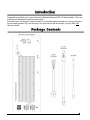
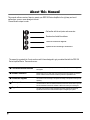
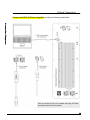
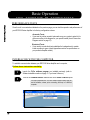
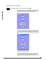
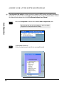
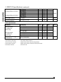
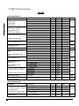
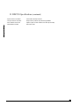
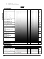
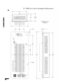
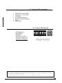
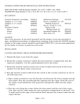
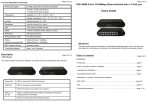
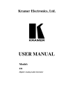
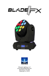
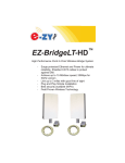
DDC 500 Series Always follow the basic precautions listed below to avoid the possibility of serious injury or even death from electrical shock, short-circuiting, damages, fire or other hazards. These precautions include the following: Power supply/Power cord/Grounding Use only floated test equipment. Oscilloscopes, PCs, signal generators, voltmeters, etc. must be connected through a three-to-two-prong adapter to avoid ground loops and other conditions that may damage the amplifier. Use only the supplied power cord. Do not place the power cord near heat sources such as heaters, or place it in a position where anyone could walk on, trip over, or roll anything over it. Do not open Do not attempt to disassemble or modify the internal components in any way. Opening the unit requires a written authorization from KSC Industries. Fire/burn/damage warning Do not insert objects (such as screwdrivers) through the amplifier’s perforated caging. This could be hazardous to you and could cause permanent damage to the Plate Amplifier. Doing so, voids the product warranty. Do not touch any speaker leads together from different drivers while the unit is powered; this could damage one or more amplifier modules. Do not touch the aluminum enclosure with any of the speaker leads while the unit is turned on; this could damage the associated amplifier module. Do not place the Plate Amplifier close to a hot surface. Loudspeaker connection Read the Amplifier specifications (page 22) before connecting loudspeaker loads and applying input signals. Check the Connection Diagrams section (page 12) to properly connect the drivers and avoid damage to them. Operation Your DDC 500 Series Amplifier is factory programmed to 0dB Output Gain; please take your precautions before applying any audio signal to the input. Read the Amplifier specifications (page 22) before connecting loudspeaker loads. Do not operate the LF, MF and/or HF amplifier sections (depending on the model) to Max Power when all the channels are set to flat response without crossover filters. Such settings will force the amplifiers with lower power rating to exceed the maximum output and may result in failure. Do not run unfiltered high frequency test signals (5-20 kHz) for more than a few seconds since this could cause permanent damage to the Amplifier. Make sure to run the amplifier with all channels connected to a load. Always turn off the unit when not in use. KSC Industries cannot be held responsible for damage caused by improper use or modifications to the amplifier system. CAUTION: TO REDUCE THE RISK OF ELECTRIC SHOCK, DO NOT REMOVE BACK COVER. The exclamation point within the equilateral triangle is intended to alert the user to the presence of important operating instructions in the literature of the product. The lightning flash with arrowhead symbol, within the equilateral triangle, is intended to alert the user to the presence of un-insulated “dangerous voltage” within the product’s enclosure that may be of sufficient magnitude to constitute a risk of electrical shock. FCC Information (U.S.A.) This device complies with Part 15 of the FCC rules. Operation is subject to the following conditions: (1) This device may not cause harmful interference, and (2) This device must accept any interference received, including interference that may cause undesired operation. Congratulations and thank you for your purchase of the Digmoda Professional DDC 500 Series Amplifier. We’re sure it will meet your demands and exceed your expectations. Please take time to look through this manual carefully. It’s packed with important information on how to get the most from this amazing product. Dig in, see how easy it is to setup and work with this amplifier, and enjoy! Note: USB cable not included. DDC 500 Series Amplifier This manual outlines a series of steps to operate your DDC 500 Series Amplifier in the right way and avoid malfunctions, errors or even damage to the unit. Please follow the steps in order: Get familiar with the unit parts and connectors Download and install the software Follow the connection diagrams Operate the unit according to instructions The manual is organized into 5 main sections and it’s been designed to get you started fast with the DDC 500 Series Amplifier Basics. These sections are: The connectors and indicators Use this section to identify the parts of the DDC Amplifier prior to connecting power and signals. Software installation Before going on to any other part of the manual, we strongly suggest you read this section. It shows how to install the necessary software to operate the unit. Connection diagrams Basic operation Appendices This section covers the wiring of the system according to the specific model you are operating. Use this section to learn the essential features that the DDC series offers to you and how the hardware interacts with software to deliver the sound you’re looking for. This part of the manual contains important information regarding the electrical specifications as well as mechanical data helpful to integrate your system. 8 The Connectors & Indicators Basic Operation Front panel………………………8 Back panel...…………………….…8 Connectors & Indicators Description……9 Connectors Detail & Pin-out………..10 Software Installation 11 Performance Tests……………16 Interfacing with the Computer….…16 A Brief Look At The Software Program …………18 22 Appendices Step1………………..……….……………. 11 Step 2...………………………….…………11 Step 3...……………………………………11 Step 4...………………………….…….…11 Step 5..………………………….…………11 Connection Diagrams 16 I. 552 Specifications…………….22 II. 550 Specifications……………24 III. 520 Specifications…………..26 IV. Mechanical Dimensions……28 V. Computer Requirements….…29 VI. Contact Info..………….…… 29 12 DDC552 Driver Wiring & Software Routing ………………………………..…12 DDC550 Driver Wiring & Software Routing ………………………………..…13 DDC520 Driver Wiring & Software Routing ………………………………..…14 System Connection …………………………………15 The Connectors & Indicators Back Panel Front Panel Connectors & Indicators Description Signal Throughput Connector AC Power In Receptacle This connector allows a pass through of the audio signal to other devices. One application might be a daisy-chain setup connecting more than one DDC Series Amplifier. Connect the provided AC cord to the line voltage (120V or 230V depending on the product model) here. Signal Input Connector Use this connector to input the source audio signal to be processed and amplified by your DDC unit. This is a helpful AC power pass-thru connection which can be used to connect several DDC units in a daisy-chain fashion avoiding the need for additional electrical outlets. LED Power Indicator Heatsink This LED will be lit as long as the system is ON (connected to AC line voltage.) An important part of the DDC Series design is the heatsink plate, which minimizes the chances for overheating, letting the amplifier modules and the overall system run cool. LED Protection Indicator AC Power Out Receptacle Speaker Connector This LED will turn on temporarily when AC is applied to the unit (as part of the start-up sequence) and permanently when thermal protection has been triggered or when a short circuit has been detected. Use this connector to plug in the speaker cable (provided in the package) and to connect the wires to the corresponding driver, depending on the amplifier model. Serial Communication Port (USB) Aluminum enclosure This port allows communication between the DDC Series Amplifier and your computer. This communication is necessary to load configuration files and to allow data transfer during the process of fine tuning and customizing your system. All DDC Series Amplifiers come shielded with a perforated aluminum enclosure to provide protection. Connectors Detail & Pin-out [552 MODEL] Pin Out 3 6 2 5 1 4 HF Module Pos + HF Module Neg – MF Module Pos + MF Module Neg – LF Module Pos + LF Module Neg – [550 MODEL] Pin Out 3 6 2 5 1 4 N/A N/A MF Module Pos + MF Module Neg – LF Module Pos + LF Module Neg – [520 MODEL] Pin Out 3 6 2 5 1 4 HF Module Pos + HF Module Neg – N/A N/A LF Module Pos + LF Module Neg – Software Installation Download and install the software All DDC 500 Series Amplifier Systems can perform a diversity of functions through powerful DSP chips that can deliver amazing results in sound characteristics and frequency response. In order to bring the power of these functions to your hands, a computer program called D-Pro Software has been developed. To download and install the D-Pro Software follow these next steps. Step 1 Go to the Digmoda web site: http://www.kscind.com/digmoda/ Step 2 Click on the button located in the lower right corner. Step 3 A login window will appear asking for username and password. † Enter the information in the corresponding boxes. Step 4 Once you are logged in, copy the folder named ------- to your computer and un-compress the D-PRO.zip file. Step 5 Open the folder where you saved the information and execute (double-click) the file “setup.exe” to install the software. If an older version of this program is already installed on your PC, executing “Setup.exe” will uninstall the older version allowing you to replace it with the newer one (re-run Setup.exe if this is the case for you). The “D-Pro window Software User's Manual” can be launched from the “Help!” Menu on the main screen once the software is running. † User name and Password are provided to you upon your purchase of the product. Connection Diagrams DDC552 – Driver Wiring Hard-wiring Wire the Amplifier based on the diagram shown below. Consult Speaker Wire Connector Details and Pin-out on page 10. Highs 250 W Amplifier Input XLR (Mono) 500 W Amplifier Mid-Range 500 W Amplifier Lows Software Routing E ach amplifier module inside the DDC552 is routed to an individual logic channel. Each of these channels is a dedicated processing unit responsible for achieving a very specific sound characteristic by means of a collection of powerful filters which include: HP, LP, BP, Parametric EQ, Bass Shelf, Treble Shelf as well as other DSP functions like Compression, Delay and Phase Inversion. By default the Configuration for the DDC552 has been programmed with the logic channel routing and filtering represented in this diagram. Logic channel 6 Audio Signal Highs Logic channel 4 Mid-Range Logic channel 1 Lows DDC550 – Driver Wiring Hard-wiring Wire the Amplifier based on the diagram shown below. Consult Speaker Wire Connector Details and Pin-out on page 10. N/A Input XLR (Mono) 500 W Amplifier Highs 500 W Amplifier Lows Software Routing E ach amplifier module inside the DDC552 is routed to an individual logic channel. Each of these channels is a dedicated processing unit responsible for achieving a very specific sound characteristic by means of a collection of powerful filters which include: HP, LP, BP, Parametric EQ, Bass Shelf, Treble Shelf as well as other DSP functions like Compression, Delay and Phase Inversion. By default the Configuration for the DDC550 has been programmed with the logic channel routing and filtering represented in this diagram. N/A Audio Signal Logic channel 4 Highs Logic channel 1 Lows DDC520 – Driver Wiring Hard-wiring Wire the Amplifier based on the diagram shown below. Consult Speaker Wire Connector Details and Pin-out on page 10. Highs 250 W Amplifier Input XLR (Mono) N/A 500 W Amplifier Lows Software Routing E ach amplifier module inside the DDC552 is routed to an individual logic channel. Each of these channels is a dedicated processing unit responsible for achieving a very specific sound characteristic by means of a collection of powerful filters which include: HP, LP, BP, Parametric EQ, Bass Shelf, Treble Shelf as well as other DSP functions like Compression, Delay and Phase Inversion. By default the Configuration for the DDC520 has been programmed with the logic channel routing and filtering represented in this diagram. Logic channel 6 Highs N/A Audio Signal Logic channel 6 Lows System Connection Connect the DDC 500 Series Amplifier according to the drawing shown below. Once you connect the unit to the computer and supply AC Power, the computer will find the new hardware. Basic Operation PERFORMANCE TESTS Once the unit is connected as indicated on the previous page, you can test the operation and performance of your DDC 500 Series Amplifier in its factory configuration scheme. Acoustic Tests o If you want to perform acoustic tests make sure your system is wired to the drivers according to the diagram for your specific model (check Connection Diagram section on page 16). Electrical Tests o If you need to run electrical tests substitute the loudspeakers for resistor loads according to specs (check Appendices section for specifications on your particular amplifier model). INTERFACING WITH THE COMPUTER To establish communication between your DDC 500 Series Amplifier and a computer, Follow these instructions carefully: 1 2 Launch the D-Pro software program you installed previously (refer to Software Installation section on page 11 if you haven’t done so). Click on the Communications TAB and click on the Select COM Port option. This step is required once. You don’t need to repeat it every time you use the software, unless you’re connecting the Amp to a different computer. Interfacing with the computer 3 A new window will show up. Click on the button labeled SCAN. The program will scan for an available COM Port and once it finds it, it will use it to communicate your DDC Amplifier with the PC. As soon as the program finds and assigns a Communications Port you will see the word SUCCESSFUL appearing in the scan status box. Click on EXIT to close this window Your amplifier is now ready to receive information from the computer and process audio through powerful DSP chips and functions. A BRIEF LOOK AT THE SOFTWARE PROGRAM The only goal of this section is to show you how to access the DSP functions and modify parameters in real time so you can hear and/or see the difference instantaneously. To fully understand and learn all about the software functions please refer to the D-Pro Windows Software User’s Manual. 1 Click on the Configuration TAB and click on DSP I/O Board Configuration option. With this step we will tell the program to load the default configuration for the Amplifier model we’re testing. 2 A new window will show up. Click on the drop-down arrow and click on your amplifier model. A brief look at the software program 3 A warning will show up: “This action will write over your current DSP configuration. Do you wish to continue?” You can click on YES due to the fact that you’re running the software for the 1st time and you don’t have any user configuration files to lose. If you had been working for hours on a custom configuration and you attempted to load the default I/O Board Configuration, you would lose all your data if you didn’t save it before. Click on EXIT to close this window A brief look at the software program 4 Click on the Configuration TAB and click on DSP Block Configuration option. This will take you to a new screen that shows a Block Diagram representing all the DSP functions available to you. Clicking on any of these blocks will bring up a new window containing all the parameters and controls necessary to make any desired adjustments to the corresponding block. DSP Functions Mid Range Driver Routed to channel 4 High Freq. Driver Routed to channel 6 DSP chip #2 is being used Example of a Block Diagram Screen [DDC552 Amplifier Model] A brief look at the software program 5 Click on any of the blocks to access its respective set of controls and graphical representations. You can modify them as you wish, but in order to apply your changes in real time (for quick checking) you will need to enable the LiveUpdate. To do this, go to the Communications TAB and click on Enable LiveUpdate. A message will pop up on the screen telling you that the Live Update option is being activated. Once it disappears you can continue. 6 Change the DSP functions freely. Filters, soft volume, limiter/compressor, etc… All modifications you make will affect the output in real time. If there are drivers connected to the unit you’ll hear how the sound changes immediately. Once you’re done testing the program simply close it without saving anything For further details on how to take advantage of all the software and DSP functions and how to transfer your modifications (temporarily or permanently) to the Amplifier, please refer to the D-Pro Windows Software User’s Manual. You can access the manual directly on the D-Pro screen. Just click on the HELP! TAB and select the Launch User’s Manual option. Appendices I. DDC552 Specifications DDC552 Audio Specifications Parameter THD+N in 4Ω (AES17 filter) THD+N in 8Ω (AES17 filter) Max THD+N in 4Ω (AES17 filter) -10dBFS Max THD+N in 8Ω (AES17 filter) -10dBFS THD+N Low Level in 4Ω THD+N Low Level in 8Ω Nominal Voltage Gain (Av) Frequency Response (Po = 1W) Common Mode Rejection (CMR) Signal to Noise Ratio in 4Ω (SNR) Signal to Noise Ratio in 8Ω (SNR) Input Impedance (Zin) Input Sensitivity in 4Ω (Balanced) (Vin) Input Sensitivity in 8Ω (Balanced) (Vin) DC Output Offset in 4Ω (DCoff) DC Output Offset in 8Ω (DCoff) Conditions f = 40Hz, Po = 1W f = 500Hz, Po = 1W f = 1KHz, Po = 1W f = 40Hz, Po = 1W f = 500Hz, Po = 1W f = 1KHz, Po = 1W f = 40Hz f = 500Hz f = 1KHz f = 40Hz f = 500Hz f = 1KHz f = 40Hz, 100mW f = 500Hz, 100mW f = 1KHz, 100mW f = 40Hz, 100mW f = 500Hz, 100mW f = 1KHz, 100mW f = 40Hz f = 500Hz f = 1KHz 20Hz - 100Hz 100Hz - 2KHz 2KHz - 20KHz 20Hz - 20KHz 0dB = 1% THD, 40Hz 0dB = 1% THD, 500Hz 0dB = 1% THD, 1KHz 0dB = 1% THD, 40Hz 0dB = 1% THD, 500Hz 0dB = 1% THD, 1KHz Unbalanced Balanced f = 40Hz, 500W f = 500Hz, 500W f = 1KHz, 225W f = 40Hz, 250W f = 500Hz, 250W f = 1KHz, 112W Low channel Mid channel High channel Low channel Mid channel High channel Min - - Typ 0.009 0.025 0.019 0.007 0.016 0.013 0.006 0.008 0.010 0.006 0.008 0.010 0.02 0.04 0.07 0.02 0.04 0.05 29.92 29.97 29.98 +/-0.5 +/-0.5 +/-0.5 -55 -135 -125 -110 -136 -125 -105 18K 36K 1.43 1.42 0.99 1.42 1.40 0.95 3.0 3.3 4.3 9.5 4.0 4.3 Max 0.011 0.031 0.024 0.009 0.020 0.016 0.008 0.010 0.013 0.008 0.010 0.013 Unit % % % dBV +/-1 +/-1 dB +/-1 dB dB Ω Vrms mVrms 1. DDC552 Specifications (continued) DC Output Offset in 4Ω (DCoff) DC Output Offset in 8Ω (DCoff) Input Clipping (Vinclip) Damping Factor (Df) (On three amplifiers) Low channel Mid channel High channel Low channel Mid channel High channel f = 1KHz 3.0 3.3 4.3 9.5 4.0 4.3 12 f = 100Hz, RL = 8Ω mVrms dBu 2000 Power Specifications Parameter Max output power 1% THD+N (Po) (AES17 filter) Max output power 1% THD+N (Po) (AES17 filter) Conditions RL RL RL RL RL RL RL = = = = = = = Min 4Ω, 40Hz 4Ω, 500Hz 2.7Ω, 1KHz 4Ω, 1KHz 8Ω, 40Hz 8Ω, 500Hz 8Ω, 1KHz - Unit - - 19.3 - Idle (115VAC/60Hz) -Input Connector: XLR female -Power Switch: Neutrik, PowerCon -Thru-put Connector: XLR Male -Output Circuitry: Class-D amps with analog feedback -Power Indicator: Green LED -Speaker output connector: MOLEX 03-09-2062 (On the back) -Fault Indicator: Red LED -DSP Control: USB Max 500 500 250 225 250 250 112 Power Draw at Idle (Pidle) (115VAC/60Hz) Typ W - W II. DDC550 Specifications DDC550 Audio Specifications Parameter Conditions THD+N in 4Ω (AES17 filter) THD+N in 8Ω (AES17 filter) Max THD+N in 4Ω (AES17 filter) -10dBFS Max THD+N in 8Ω (AES17 filter) -10dBFS f = 40Hz, Po = 1W f = 500Hz, Po = 1W f = 40Hz, Po = 1W f = 500Hz, Po = 1W f = 40Hz f = 500Hz f = 40Hz f = 500Hz f = 40Hz, 100mW f = 500Hz, 100mW f = 40Hz, 100mW f = 500Hz, 100mW f = 40Hz f = 500Hz 20Hz - 100Hz 100Hz - 20KHz 20Hz - 20KHz 0dB = 1% THD, 40Hz 0dB = 1% THD, 500Hz 0dB = 1% THD, 40Hz 0dB = 1% THD, 500Hz Unbalanced Balanced f = 40Hz, 500W f = 500Hz, 500W f = 40Hz, 250W f = 500Hz, 250W Low channel High channel Low channel High channel f = 1KHz THD+N Low Level in 4Ω THD+N Low Level in 8Ω Nominal Voltage Gain (Av) Frequency Response (Po = 1W) Common Mode Rejection (CMR) Signal to Noise Ratio in 4Ω (SNR) Signal to Noise Ratio in 8Ω (SNR) Input Impedance (Zin) Input Sensitivity in 4Ω (Balanced) (Vin) Input Sensitivity in 8Ω (Balanced) (Vin) DC Output Offset in 4Ω (DCoff) DC Output Offset in 8Ω (DCoff) Input Clipping (Vinclip) Damping Factor (Df) (On three amplifiers) Min - - f = 100Hz, RL = 8Ω Typ 0.009 0.025 0.007 0.016 0.006 0.008 0.006 0.008 0.02 0.04 0.02 0.04 29.92 29.97 +/-0.5 +/-0.5 -55 -135 -125 -136 -125 18K 36K 1.43 1.42 1.42 1.40 3.0 3.3 9.5 4.0 12 Max Unit 0.011 0.031 0.009 0.020 0.008 0.010 0.008 0.010 % % % dBV +/-1 +/-1 dB dB dB Ω Vrms mVrms dBu 2000 Power Specifications Parameter Conditions Max output power 1% THD+N (Po) (AES17 filter) RL RL RL RL Max output power 1% THD+N (Po) (AES17 filter) = = = = 4Ω, 4Ω, 8Ω, 8Ω, Min 40Hz 500Hz 40Hz 500Hz Max Unit - 500 500 250 250 - W - 18 - W Power Draw at Idle (Pidle) (115VAC/60Hz) Idle (115VAC/60Hz) -Input Connector: XLR female -Power Switch: Neutrik, PowerCon -Power Indicator: Green LED -Speaker output connector: MOLEX 03-09-2062 (On the back) -Fault Indicator: Red LED -DSP Control: USB -Thruput Connector: XLR Male Typ with analog feedback -Output Circuitry: Class-D amps II. DDC550 Specifications (continued) -Input Connector: XLR female -Power Switch: Neutrik, PowerCon -Thru-put Connector: XLR Male -Output Circuitry: Class-D amps with analog feedback -Power Indicator: Green LED -Speaker output connector: MOLEX 03-09-2062 (On the back) -Fault Indicator: Red LED -DSP Control: USB III. DDC520 Specifications DDC520 Audio Specifications Parameter Conditions THD+N in 4Ω (AES17 filter) THD+N in 8Ω (AES17 filter) Max THD+N in 4Ω (AES17 filter) -10dBFS Max THD+N in 8Ω (AES17 filter) -10dBFS f = 40Hz, Po = 1W f = 1KHz, Po = 1W f = 40Hz, Po = 1W f = 1KHz, Po = 1W f = 40Hz f = 1KHz f = 40Hz f = 1KHz f = 40Hz, 100mW f = 1KHz, 100mW f = 40Hz, 100mW f = 1KHz, 100mW f = 40Hz f = 1KHz 20Hz - 100Hz 100KHz - 20KHz 20Hz - 20KHz 0dB = 1% THD, 40Hz 0dB = 1% THD, 1KHz 0dB = 1% THD, 40Hz 0dB = 1% THD, 1KHz Unbalanced Balanced f = 40Hz, 500W f = 1KHz, 225W f = 40Hz, 250W f = 1KHz, 112W Low channel High channel Low channel High channel f = 1KHz THD+N Low Level in 4Ω THD+N Low Level in 8Ω Nominal Voltage Gain (Av) Frequency Response (Po = 1W) Common Mode Rejection (CMR) Signal to Noise Ratio in 4Ω (SNR) Signal to Noise Ratio in 8Ω (SNR) Input Impedance (Zin) Input Sensitivity in 4Ω (Balanced) (Vin) Input Sensitivity in 8Ω (Balanced) (Vin) DC Output Offset in 4Ω (DCoff) DC Output Offset in 8Ω (DCoff) Input Clipping (Vinclip) Damping Factor (Df) (On three amplifiers) Min Typ - 0.009 0.019 0.007 0.013 0.006 0.010 0.006 0.010 0.02 0.07 0.02 0.05 29.92 29.98 +/-0.5 +/-0.5 -55 -135 -110 -136 -105 18K 36K 1.43 0.99 1.42 0.95 3.0 4.3 9.5 4.3 12 - f = 100Hz, RL = 8Ω Max Unit 0.011 0.024 0.009 0.016 0.008 0.013 0.008 0.013 % % % dBV +/-1 +/-1 dB dB dB Ω Vrms mVrms dBu 2000 Power Specifications Parameter Conditions Max output power 1% THD+N (Po) (AES17 filter) RL RL RL RL Max output power 1% THD+N (Po) (AES17 filter) = = = = 4Ω, 40Hz 2.7Ω, 1KHz 8Ω, 40Hz 8Ω, 1KHz Power Draw at Idle (Pidle) (115VAC/60Hz) Idle (115VAC/60Hz) -Input Connector: XLR female -Power Switch: Neutrik, PowerCon -Thruput Connector: XLR Male Min Typ Max Unit - 500 250 250 112 - W - 15 - W -Output Circuitry: Class-D amps with analog feedback -Power Indicator: Green LED -Speaker output connector: MOLEX 03-09-2062 (On the back) -Fault Indicator: Red LED -DSP Control: USB III. DDC520 Specifications (continued) -Input Connector: XLR female -Power Switch: Neutrik, PowerCon -Thru-put Connector: XLR Male -Output Circuitry: Class-D amps with analog feedback -Power Indicator: Green LED -Speaker output connector: MOLEX 03-09-2062 (On the back) -Fault Indicator: Red LED -DSP Control: USB IV. DDC5xxx Series Mechanical Dimensions V. Computer Requirements Windows XP Pro or Home Edition Intel Pentium 4, 1 GHz (or better) 512 MB RAM 60 (or greater) GB Hard-Drive 1024x768 (or better) Video Display Mouse 1 free USB port VI. Contact Information KSC Industries, Inc. 881 Kuhn Drive Building 200 Chula Vista, CA 91914 Telephone: (619) 671-0110 www.kscind.com/digmoda/ D-Pro™, Digmoda® and KSC™ are trademarks of KSC Industries, Inc. All other trademarks and registered trademarks are the property of their respective license holders. Design ©2008 KSC Industries, Inc. All rights reserved.