1
USER MANUAL
ScratchDuino.Robokit
St.Petersburg
2015
JSC “Tyrnet”
ScratchDuino.Robokit
St.Petersburg
JSC “Tyrnet”
2015
Printed by the order of
JSC “Tyrnet”
Reviewers:
— Professor Irina B. Gotskaya, EdD, Chairperson of IT Education Methodology
Dept. at Herzen State Pedagogical University (St.Petersburg);
— Yuriy A. Vinnitskiy, Cand.Sc. (Education), IT teacher, CEO Deputy over Experimental Work at School № 169 with intensive study of English language
(St.Petersburg).
Elena A. Vostrikova
ScratchDuino.Robokit: User Manual / Elena A. Vostrikova, Leonid S. Zakharov,
Ekaterina A. Lvova. — St.Petersburg: Reprographics Center of JSC “Tyrnet”, 2015.
— 70 p.
This User Manual is intended for school teachers, educators, or parents — users of ScratchDuino.Robokit, which is an electronic kit of light sensor, line detector, touch probe, the infrared “eye” sensor, and modules to create your
own sensors.
The manual provides instructions on installing the software for the four major
operating systems (OS); a list of components in the box, description of the sensors; brief information about ScratchDuino and Scratch software; examples of
working scripts; instructions on registering and placing individual projects at
wiki.scratchduino.com, as well as the cases of organizing children’s and adults’
cooperation within the framework of the festival “ScratchDuino Libre Robotics”.
© JSC “Tyrnet”, 2015
Table of Contents
Installing the Software for ScratchDuino.Robokit ............................................... 4
Windows OS Family ........................................................................................ 4
Linux OS Family ............................................................................................... 7
Mac OS Family .............................................................................................. 11
Android OS Family ........................................................................................ 12
Connecting ScratchDuino.Robokit via Bluetooth, for Windows ................... 16
Connecting ScratchDuino.Robokit via Bluetooth, for Linux ........................... 17
Connecting ScratchDuino.Robokit via Bluetooth, for Mac OS ....................... 19
Running Software from a USB Stick without Installation on the Hard Drive .. 22
Provisions for Implementing the Projects ........................................................ 25
Connecting ScratchDuino.Robokit ................................................................ 27
Setting up a Playground for Creative Activity and Contests .......................... 30
Sensors Testing and Calibration .................................................................... 33
Attaching the Sensors ................................................................................... 35
Basic Concepts of ScratchDuino .................................................................... 37
Basic Algorithms of ScratchDuino ................................................................. 40
Co-operation of the Sensors and the Motor ..................................................... 45
Touch Probe.................................................................................................. 45
Line Detector ................................................................................................ 48
Light Sensor .................................................................................................. 50
IR Eye Sensor ................................................................................................ 52
Promoting the Community of the Like-Minded ................................................ 53
Wiki Portal of Project ScratchDuino: Signing up ............................................ 53
wiki.scratchduino.com: Uploading a Project ................................................. 60
Rules on Discussing the Projects at wiki.scratchduino.com........................... 63
Information Sources for Project ScratchDuino ................................................. 66
Appendix .......................................................................................................... 67
Statutes of ScratchDuino Libre Robotics Festival .......................................... 67
4
Installing the Software for ScratchDuino.Robokit
Windows OS Family
To work successfully with ScratchDuino.Robokit under Windows, it
is necessary to install the visual programming environment for
Scratch 1.4, software for ScratchDuino.Robokit robot, and Arduino
UNO driver. In addition, advanced users might want to install
Arduino IDE — the integrated developer’s environment for Arduino UNO.
The software can be obtained:
from the CD, shipped with ScratchDuino.Robokit;
from the file server of the project — http://files.scratchduino.ru/.
Installation from the CD or from the File Server of the Project
1.
How to install Scratch:
Run the installation file ../windows/Scratchduino.exe from the CD,
or download and run the installation file from the file server:
http://files.scratchduino.ru/Software/Windows/Scratchduino.exe.
Result: both Scratch and ScratchDuinoRobot will be installed.
The Installation Wizard will ask you to choose a language — choose English, then press Ок, Next, and Install.
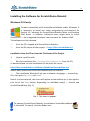
Result: In a few seconds, two icons will appear at the desktop (or in the application list of the Start button, depending on individual setup) — Scratch and
ScratchDuinoRobot (Fig. 1).
Fig. 1. The icons to appear.
To operate ScratchDuino.Robokit, the software ScratchDuinoRobot
is intended! To launch, click the Robot icon.
5
2.
How to install the driver:
run the executable ../windows/ ScratchDuino_drivers.exe from CD,
or download it from the file server
http://files.scratchduino.ru/Software/Windows/ScratchDuino_drivers.exe
and run.
In the dialog boxes of the Installation Wizard, click Yes, then Next, Install,
and Finish.
Fig. 2. Dialog boxes of Installation Wizard.
A note for users. You will not find any Arduino IDE software either on the CD or
on the file server of the project. This is intentional, as with Arduino IDE installed
it is possible to reprogram the pre-programmed Arduino UNO cartridge. Hence,
to avoid confusions, we do not recommend Arduino IDE installation for
inexperienced users. However, if you do realize what you’re dealing with, you
can happily install the Arduino IDE software from the developer’s website (see
the next section).
6
How to Install the Arduino IDE Software from the Developer’s Website
Download the fresh version of the Arduino IDE software from the developer’s
website https://www.arduino.cc/en/Main/Software and follow the installation instructions: https://www.arduino.cc/en/Guide/Windows.
How to Connect ScratchDuino.Robokit via USB Cable
Plug the USB cable, shipped along with ScratchDuino.Robokit, into the USB port
of the PC and into the Arduino UNO cartridge. To ensure the communication
between the ScratchduinoRobot and ScratchDuino.Robokit, you need to know
the number of serial port connecting ScratchDuino.Robokit to the PC. For this
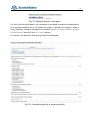
purpose, go to Device Manager, usually found at Control Panel.
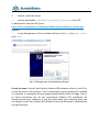
Fig. 3. A snapshot of Device Manager window, showing the number
of serial (COM) port, to which Arduino UNO is connected automatically.
Remember the number of the COM port! It is the port you’ll need to select
in ScratchDuinoRobot. In Fig. 3, Arduino UNO matches the port COM9.
7
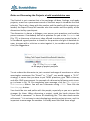
Linux OS Family
There are three ways to install the ScratchDuino.Robokit software for GNU/Linux OS family:
Use the CD, shipped with the kit;
Download the packages from the file server of the project
http://files.scratchduino.ru/;
Install from a dedicated repository containing the installation packages
for ScratchDuino.Robokit software:
http://download.opensuse.org/repositories/home:/scratchduino/.
ScratchDuino software is based on Scratch 1.4. It is not recommended to
install scratch_1.4 and virtual machine squeak-vm via the official repositories of your Linux distribution or download from the developer’s website. In
such a case, Scratch will not work with a serial port, and therefore, you will
not be able to program ScratchDuino.Robokit via ScratchDuino software. Please
note that that the version of the package for the virtual machine squeak-vm,
based on which Scratch 1.4 operates, must be 4.0.3-2202.
Installation from the CD
The packages for installing the software under an OS of Linux family are on the
CD in the ../linux folder.
Installation packages are built for some of the most common Linux distributions (RHEL/CentOS, Fedora, Scientific Linux, Ubuntu, Debian, openSUSE, SLED),
and found in a folder with the appropriate name mentioning the version of the
distribution. If there is no distribution you need, select a distribution, closest to
the desired. For example, to install ScratchDuino on Linux Mint 17, use the
packages from the ../linux/xUbuntu14.04/ folder.
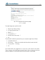
For Deb-based distributions, install the packages scratch 1.4.0.7, squeak-vm
4.0.3, squeak-plugins-scratch, and scratchduino.
For RPM-based distributions, install the packages squeak-vm 4.0.3, scratch
1.4.0.6, and scratchduino.
8
After the successful installation, you will find the launcher icons for Scratch
and ScratchDuino
at your graphical desktop.
You can run Scratch and ScratchDuino from the console; for this, type scratch
or scratchduino, respectively, at the command prompt.
Installation from the File Server of the Project
The installation is similar to the installation from the CD. Download the packages that match your Linux distribution, from
http://files.scratchduino.ru/Software/Linux/, and install them.
Installation from a Repository
Add the repository for your distribution as described below:
for openSUSE and SLE, type in the console the line
$ sudo zypper addrepo
http://download.opensuse.org/repositories/home:/scratchduino/
XXXXXXX/ ScratchDuino
for CentOS, RHEL, Fedora, add
scratchduino.repo with the following contents:
a
file
/etc/yum.repos.d/
[scratchduino]
name=ScratchDuino
type=rpm-md
baseurl=http://download.opensuse.org/repositories/home:/
scratchduino/XXXXXXX/
gpgcheck=1
gpgkey=http://download.opensuse.org/repositories/home:/
scratchduino/XXXXXXX/repodata/repomd.xml.key
enabled=1
for Debian and Ubuntu, add a line to the file /etc/apt/sources.list:
deb http://download.opensuse.org/repositories/home:/
scratchduino/XXXXXXX/ /
In all cases, XXXXXXX must be replaced with the name and version of your
Linux distribution. Minor versions of the packages may differ slightly from
those shown in the Manual.
9
For Deb-based distributions, install the packages scratch 1.4.0.7, squeak-vm
4.0.3, and squeak-plugins-scratch, scratchduino from the added repository.
For RPM-based distributions, install the packages squeak-vm 4.0.3, scratch
1.4.0.7, and scratchduino from the added repository.
Post-Installation Configuring
After successful installation of the software to operate ScratchDuino.Robokit,
you will need to make some post-installation configuring.
Arduino UNO is accessed via /dev/ttyACM<number>. By default, the
/dev/tty* devices are available to the users from the dialout group only. Therefore, the user who is going to work with ScratchDuino.Robokit must belong to
the dialout group.
Add the user to the dialout group!
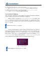
If your Linux distribution is either Ubuntu 12.04 and later or an Ubuntubased distribution (for example, Mint), you need to check your windows manager (WM). By default, it is Compiz. Unfortunately, Compiz can cause conflicts
with Scratch. That’s why it is recommended to install the package gnomesession-fallback (for Ubuntu 14.04 and later — gnome-session-flashback), so
that the WM choice would be available at the login window (Fig. 4).
Fig. 4. Login window.
When logging in, select the Metacity WM!
10
Connecting ScratchDuino.Robokit and Selecting a Port in ScratchDuino
Launch ScratchDuino from the GUI or from the console. In the ScratchDuino
window that pops up, select the blue block Sensing, then right-click on the
block Sensor and select show ScratchBoard watcher (Fig. 5).
Fig. 5. Right-click menu of the block sensor.
Then right-click on the grey background and choose select serial/usb port
(Fig. 6).
Fig. 6. Right-click menu of the ScratchBoard.
Select /dev/ttyACM0 in the drop-down list.
11
Mac OS Family
To install the software for Mac OS, it is possible to use the CD,
shipped with ScratchDuino.Robokit, or to download the installation files from the file server of the project. There is no need to
install the drivers for Arduino.
On the CD, the installation file is in the ../mac/ScratchDuino.dmg
folder.
The link to download from the file server is
http://files.scratchduino.ru/Software/Mac/ScratchDuino.dmg.
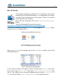
To install the software, just open Scratch.dmg and drag the ScratchDuino folder
into the Application folder (Fig. 7).
Fig. 7. The window looks like that.
Open Application in a file manager, go to the ScratchDuino folder, and run the
executable (Fig. 8).
Fig. 8. Running the executable.
In the Scratch window that appears, select the blue block Sensing, then rightclick on the block sensor value and select show ScratchBoard watcher (see
Fig. 5). Then right-click on the grey background and choose select serial/USB
port (see Fig. 6). Select /dev/cu.usbmodem1411 in the drop-down list.
12
Android OS Family
Mobile devices running the Android OS work with ScratchDuino.Robokit by
means of ScratchDuino application via Bluetooth connection.
NOTE: To work via Bluetooth, switch the jumpers located at the bottom of
ScratchDuino.Robokit (see the section “ScratchDuino.Robokit: Control via
Bluetooth”).
To install the ScratchDuino software:
find in Google Play the ScratchDuino application and click INSTALL (see
the left picture in Fig. 9);
follow the instructions of the Installation Wizard. After the installation,
click the OPEN button (see the right picture in Fig. 9).
Fig. 9. Getting ScratchDuino from Google Play.
In the menu Android device settings, activate Bluetooth and search for
Bluetooth devices. When the ScratchDuino.Robokit is detected, type in the PIN
code — 1234 (see Fig. 10).
13
Fig. 10. Establishing the Bluetooth connection between ScratchDuino.Robokit
and an Android device.
Launch the ScratchDuino application. In its top panel, select the item Devices
and then Search for devices. ScratchDuino application will be automatically
joined with ScratchDuino.Robokit (Fig. 11).
Fig. 11. Connecting ScratchDuino.Robokit
to ScratchDuino application.
14
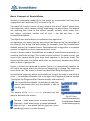
If you want to help the Project ScratchDuino, you are able to do that
right from the application. Just click the button Donate. Thanks!
Fig. 12. How to help the Project ScratchDuino.
ScratchDuino.Robokit: Control via Bluetooth
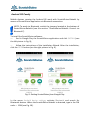
ScratchDuino.Robokit and a PC can exchange the data via either USB cable or
Bluetooth connection. Bluetooth allows the PC and the Robokit to
communicate when they are within the distance 10 m from each other (the
distance depends on the obstacles and the noise). In case of Bluetooth
connection, ScratchDuino.Robokit is powered by a battery of 6F22 type
(Crone), or by four AA batteries, or using special adapters shipped with the kit
(Fig. 13).
Fig. 13. A clamp for 6F22 battery
and the housing for four АА batteries.
15
NOTE: When powered by batteries, the Robokit wheels are rotating faster
than when powered via USB (the power voltage given by a USB socket is 5V
for peripheral devices, against 9V of a 6F22 battery).
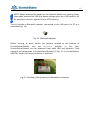
The kit includes a Bluetooth adapter, connected to the USB port of a PC or a
notebook (Fig. 14).
Fig. 14. Bluetooth adapter.
Before starting to work, switch the jumpers located at the bottom of
ScratchDuino.Robokit into the Bluetooth position. In this case,
ScratchDuino.Robokit can be powered from both USB and batteries. Take
notice of the name given to ScratchDuino.Robokit (in Fig. 15, it is Scratchduino000279). Under this name the device is detected.
Fig. 15. Position of the jumpers for Bluetooth connection.
16
Connecting ScratchDuino.Robokit via Bluetooth,
for Windows
Plug the Bluetooth adapter into a USB port. The icon of Bluetooth will appear
on the taskbar in the notification area. Right-click the icon and select Add a
Device. The PC will find all available objects. Select the desired one (in our case,
Scratchduino-000279) and click Next.
Fig. 16. The interface of Bluetooth manager.
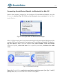
To ensure the security of Bluetooth connection, you’ll be asked to provide a
PIN code, which is 1234. Select Enter the device’s pairing code and type 1234 in
the textbox.
Fig. 17. Device pairing.
The port for the Bluetooth connection can be found through the Device
Manager, in our case it is COM13. Select this port when working with
ScratchDuinoRobot software (Fig. 18).
Fig. 18. Port of connection.
17
Connecting ScratchDuino.Robokit via Bluetooth, for Linux
To operate ScratchDuino.Robokit via Bluetooth connection under an OS of
Linux family, we recommend to install the Bluetooth manager Blueman and
work through it.
Plug the Bluetooth adapter into USB port of your PC and switch the jumpers located at the bottom of ScratchDuino.Robokit into Bluetooth position
(Fig. 15). Right-click the Bluetooth icon and select Devices… In the window that
appears, click Search. In a few seconds, the device Scratchduino-XXX will be detected (Fig. 19).
Fig. 19. The GUI of Blueman.
To communicate with ScratchDuino.Robokit, click the “bunch of keys” icon and
enter the PIN code 1234.
Fig. 20. Device pairing.
18
Next, you need to specify the way of connection — via a serial port. On a successful connection, you’ll be notified that the Scratchduino-XXX device is available via the /dev/rfcommX (where X is the port number, for example,
rfcomm0).
Fig. 21. Selection of a serial port.
When working with ScratchDuino software and selecting the port (Figs. 5, 6,
and 22), specify /dev/rfcommX.
Fig. 22. Selection of a serial port.
Depending on your version of Blueman package, the GUI of Bluetooth manager might be slightly different from the one shown in this Manual.
19
Connecting ScratchDuino.Robokit via Bluetooth, for Mac OS
Switch the jumpers located at the bottom of ScratchDuino.Robokit into the
Bluetooth position (Fig. 15). Click on the Bluetooth icon and select Set Up Bluetooth Device… .
Fig. 23. GUI of the Mac OS Bluetooth Manager.
After 5–20 seconds, the PC will have detected the Scratchduino-XXX device (the
number XXX can be found at the bottom of ScratchDuino.Robokit). On detecting the device, click Continue and in the next window, click the button
Passcode Option, select the item Use a specific passcode, and enter the code
1234.
Fig. 24. Bluetooth pairing.
Open the ScratchDuino application and when selecting a port (see Figs. 5 and 6)
specify the /dev/cu.Scratchduino-XXXXXX-DevB port.
20
Fig. 25. Selecting the port for Bluetooth connection.
Operating the Arduino IDE
ScratchDuino.Robokit can be programmed not only from ScratchDuino, but also from the Arduino IDE. The detailed discussion of this issue is beyond the
scope of this Manual.
Arduino UNO cartridge, found in the box, is shipped with ready “firmware”, that is, a program is pre-loaded in Arduino UNO (a special name of
the programs written for Arduino is “sketch”). Reprogramming the cartridge may cause the destruction of the original firmware. If some other
sketch was added to the cartridge, the original firmware must be restored, to
enable the work of ScratchDuino.Robokit with ScratchDuino IDE. For this, you
need either to use the CD (the firmware file is located in the
../firmware/sduino_laboratory_robot/sduino_laboratory_robot.ino folder), or
download this file from the file server of the project —
http://files.scratchduino.ru/firmware/sduino_laboratory_robot/
sduino_laboratory_robot.ino.
To “load” the original sketch, install the Arduino IDE from the developer’s website: https://www.arduino.cc/en/Main/Software.
Launch Arduino IDE and open (via the menu File Open) the firmware file
(Fig. 26).
Fig. 26. GUI of Arduino IDE.
21
Connect the cartridge to your PC via the USB cable. Using the GUI, make sure to
select Arduino UNO and the correct port for the device (Fig. 27).
Fig. 27. Selecting a version of Arduino.
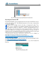
To load the firmware into your cartridge, click the Upload icon (Fig. 28). On success, you will see a notification Done uploading.
Fig. 28. Uploading a sketch.
22
Running Software from a USB Stick without Installation on the Hard Drive
In the kit, there is a USB stick with a ready version of a Linux operating system
(OS) installed. The OS includes an Arduino UNO driver and the software of
Scratch and ScratchDuino. To start working with ScratchDuino.Robokit, you only need to boot your PC from the USB stick. This option has the following advantages:
ScratchDuino.Robokit is ready to work with a PC that runs any OS, which
saves you time for software installation. Once that the USB stick is plugged in,
you can run the ScratchDuino software in a few minutes and start to do your
programming, following the instructions on page XX (Figs. 5 and 6).
You get a full-fledged working version of a Linux OS without modifying
the hard disk of your PC that remains untouched.
However, this method has certain drawbacks:
the OS boots relatively slowly;
the number of rewriting cycles for USB sticks is limited (from 10,000 to
100,000, depending on the make). The lifetime of a USB stick under a heavy usage is not very long. Therefore, if you need to use the ScratchDuino.Robokit on
a regular basis (for example, at training courses), you’ll be better off in case of
installation on the hard disk.
Below, there is a step-by-step beginner guide on booting the software from a
USB drive:
1.
Plug the USB stick in and boot (or reboot) your PC.
2.
When the BIOS starts booting, a list of the keyboard keys shows at the
screen (for a rather short time), that are able to get you into the Boot Menu.
Typically, these are F2, F8, F10, F12, and Delete. The keys are displayed at the
screen with the vendor’s logo. For a one-time changing the boot order, it’s better to use the Boot Menu; otherwise, you should change the BIOS settings.
3.
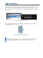
On pressing the proper key, the Boot Menu window appears (Fig. 29).
23
Fig. 29. Choice of bootable devices in the Boot Menu.
4.
Select the option with the USB stick name among the available options.
5.
Wait for the OS to boot. It takes some time.
6.
Launch ScratchDuino (see Figs. 5 and 6).
7.
Do not unplug the USB stick before shutting down your PC!
In the early versions of BIOS, there is no boot menu. In this case, you can
change the BIOS settings to enable booting from a USB device.
Be careful when changing the settings! A mistake can cause the software or
hardware failure.
Every vendor has its own idea of the BIOS menu layout, but most of the BIOS
menus include the general settings: power mode, time and date, boot order (in
Advanced BIOS Features or BIOS Features) and so on.
24
Fig. 30. Windows to select the boot order in two different versions of BIOS.
8.
Early versions of BIOS do not support mouse input. You have to navigate
the menu using the keyboard.
9.
On selecting the bootable device as USB, save the changes and close the
BIOS settings window (Fig. 31).
Fig. 31. Saving the settings in two different versions of BIOS.
25
Provisions for Implementing the Projects
Kit Components
ScratchDuino.Robokit is designed to teach students the basic programming
skills, using the measurement data obtained directly from the ambience. The
modules on offer allow to create a robotic mechanism able to send information
about the environmental conditions to a PC. Using the ScratchDuino.Robokit,
the students will get acquainted with the basic microelectronic components, as
well as with the operation of sensors, sensor calibration and configuring, and
then use this knowledge when creating their own programs.
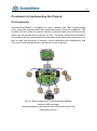
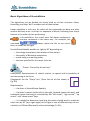
Fig. 32. Basic components of ScratchDuino.Robokit:
Arduino UNO cartridge;
wheeled platform, joined with cased microelectronic chip;
attachable sensors.
26
1
2
3
4
7
6
8
9
5
10
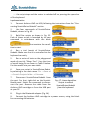
Fig. 33. Kit components: 1 — two light sensors;
2 — two touch probes; 3 — two line detectors;
4 — a 18-cm-long cable; 5 — housing for four АА batteries;
6 — one “infrared eye” sensor;
7 — two blank modules to implement individual ideas;
8 — Bluetooth adapter; 9 — a clamp for 6F22 battery; 10 — USB stick.
All the sensors and the chip are protected with a transparent plastic case.
27
Connecting ScratchDuino.Robokit
1. Install the software (refer to the section “Installing the Software for
ScratchDuino.Robokit” of this Manual).
2.
Make the ScratchDuino.Robokit assembly.
Join the Arduino UNO cartridge in a transparent case with the wheeled
platform.
Connect the Arduino UNO cartridge with the PC via the USB cable.
Put the jumpers at the bottom of ScratchDuino.Robokit into a proper position, according to the selected option of connection. At any option,
ScratchDuino.Robokit can be additionally powered from the batteries.
Remember the name of ScratchDuino.Robokit (in Fig. 34, it is
Scratchduino-000144). The device will be given this name on detecting in case
of Bluetooth connection.
Fig. 34. Two operation modes of ScratchDuino.Robokit.
3. Check the COM port, at which Arduino UNO is installed (refer to the section “Installing the Software for ScratchDuino.Robokit” of this Manual).
ScratchDuino
4.
Launch the application
(see Fig. 35).
28
1
2
3
4
5
6
7
8
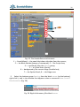
Fig. 35. The ScratchDuino environment:
1 — ScratchBoard — the panel that shows the data from the sensors;
2 — the Block Palette (groups of commands); 3 — the Script Area;
4 — commands from the Motion group;
5 — a Virtual Actor (Sprite);
6 — background of the current stage (a white box);
7 — the Sprites Panel; 8 — the Stage area.
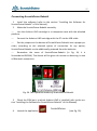
5. Select the buttons group Sensing, then the block sensor (at the bottom),
right-click it, and in the window that appears select a command show ScratchBoard watcher (Fig. 36).
Fig. 36. Right-click menu of the block sensor.
29
6. Right-click on the grey background and choose select serial/USB port
(Fig. 37).
Fig. 37. Right-click menu of ScratchBoard.
7. Attach a sensor (for example, the light sensor) to ScratchDuino.Robokit.
Note that the numeric values at the ScratchBoard have been changed. Fig. 38
shows the relation of the “sockets” at the platform and the values of variables.
Fig. 38. Sensors panel BEFORE and AFTER attachment of two sensors,
and mapping of the sensors.
30
Setting up a Playground for Creative Activity and Contests
ScratchDuino.Robokit is a dynamic Actor. It is important to cater for the conditions that show it off at its best.
We’ll consider various playgrounds for ScratchDuino.Robokit, keeping in mind
its dimensions — 160×140 mm (Fig. 39), road clearance 4 mm, and maximal
turning radius when the protruding sensors (touch probe or line detector) are
attached — 130 mm, as well as a tolerance of 50 mm for manoeuvering.
Fig. 39. Dimensions of ScratchDuino.Robokit
without protruding sensors.
1.
Testing of ScratchDuino.Robokit. For this purpose, it is enough to have a
relatively flat surface area no less than 300×300 mm. Your first testing ground
for ScratchDuino.Robokit can be a desk, a bench, or an uncluttered place on
the floor. Surround a desk or a bench with a kind of parapet, to prevent the device from dropping down.
2.
Contests and training in the Trajectory nomination. Basic component for
the ScratchDuino.Robokit playground is a 300×300 mm square tile.
ScratchDuino.Robokit is able to travel a route (Fig. 40) using the line detector.
Variation of the line thickness (from 25 to 50 mm) affects the travel time. During the development of the algorithms, it is possible to relate the line thickness
and the robot’s speed with each other. At a contest, both the fact of passing the
route and the travel time count. The complicated routes can be made as a pattern of the tiles. For training purposes, it is enough to print out the tiles using a
black-and-white printer and join them in the required order with glue.
31
“Winding”
“Sharp Turn”
“Side Road”
“Right Line”
“Smooth Turn”
“Crossroad”
“Inverted
Smooth Turn”
“Inverted
Crossroad”
“Inverted
Right Line”
Fig. 40. Tiles to pave the playground.
3.
Contests and training in the Labyrinth (a maze) nomination are carried
out in a field made of compartments. A basic compartment of the labyrinth occupies an area of size 300×300 mm; its height is 100 mm or taller.
START
FINISH
Fig. 41. A simple labyrinth for ScratchDuino.Robokit,
1200×600×130 mm.
32
IR Eye lets the ScratchDuino.Robokit traverse a simple labyrinth1, which can be
made of a lightweight and endurable material, for example, foamed plastic.
A plan view of such a labyrinth is shown in Fig. 41.
The playground is a hallmark of robot competitions: its general configuration
has been kept for years, only its details sometimes vary. ScratchDuino.Robokit
helps to get ready for more complicated competitions in the Labyrinth and Trajectory nominations.
4.
Except for the contests, the playground of ScratchDuino.Robokit can be
used at implementing creative projects. In this case, the dimensions and the
shape of the playground is limited by author’s imagination only. For example,
Fig. 42 shows a piece of an unusual shape for a creative project “Canyon”. The
authors’ idea is to equip the ScratchDuino.Robokit with a video camera shooting a film while the protagonist is overcoming a dangerous ravine.
Fig. 42. The route for the “Canyon” project.
1
See https://youtu.be/0u2x_7lnSyo.
33
Sensors Testing and Calibration
To be able to create the projects, to modify the ready ones, and to construct
the new kinds of sensors, you need to study the sensors shipped with
ScratchDuino.Robokit. Despite their being standard, the sensors in different
kits can have their own individual ranges of sensitivity. One by one, attach your
sensors to ScratchDuino.Robokit, make the measurements as described below,
and fill Table 1:
Put in front of ScratchDuino.Robokit, at a distance of up to 20 cm, a blind
alley of an inverted-U shape, as an obstacle, to check the Infrared (hereinafter,
IR) Eye. Study the relation between the values of analog0, analog3, and analog4
variables at ScratchBoard and the distance to the obstacle.
Put ScratchDuino.Robokit, with the line detector attached, into three different positions sequentially: on a white surface, on a black surface, and above
the desk’s edge. Make sure that the values substantially differ, for example, 3
against 23.
Expose the light sensor to the different light sources. Simulate night, twilight, and noon conditions. Determine the sensor’s range and put the data into
Table 1. Repeat this procedure with the other sensor. Its range may differ.
Press the button of the touch probe. Make sure that the variable takes
only two values: 0 and 100.
Table 1. Probable Sensitivity Ranges of ScratchDuino.Robokit’s
Sensor and Buttons
Sensor
Infrared eye.
Zones: left, straightway, right
Optical sensor (line detector 1)
Optical sensor (line detector 2)
Photo resistor (light sensor 1)
Photo resistor (light sensor 2)
Contact switch (touch probe)
(both sensors)
Minimal value
Maximal value
21
96
3
3
6
61
0
20
21
56
95
100
34
IR Eye is used to detect the obstacles at a distance up to 20 cm. The IR Eye
hardware board can be conventionally divided into three parts (Fig. 43):
— the central part is responsible for detecting an obstacle in front of
ScratchDuino.Robokit;
— left and right parts (each with two photo transistors and one LED) are responsible for the obstacles to the left and to the right, respectively.
Fig. 43. IR Eye: three zones to detect the obstacles.
The motion of ScratchDuino.Robokit is caused by (Fig. 44):
1)
2)
two reduction motors with rubber wheels to rotate;
two ball bearings, fastened at the platform fore and aft.
Fig. 44. Motion devices: a reduction motor with wheel
and a ball bearing.
All the values read by the sensors (except for the touch probe) depend on the
illumination in the room and the position of the light sources.
Keep in mind that the power voltage provided by a USB port is ~5V. It is enough
for ScratchDuino.Robokit to work, but its speed will be not very great. The voltage can be raised by an extra power source: a 6F22 battery, or four AA batteries, or an accumulator. The kit includes two ready devices that can be used in
case of USB connection to provide additional power. In case of Bluetooth
35
connection, a power source is a must to have, because the ScratchDuino.Robokit cannot move without the batteries. When the power voltage increases, the speed of ScratchDuino.Robokit increases too.
It is important to know that an algorithm, developed for a USB connection
5V), can produce deviations (or will not work at all) when ScratchDuino.Robokit is powered with an extra source, as well as in the case of
Bluetooth connection.
Attaching the Sensors
All the sensors of ScratchDuino.Robokit are held in place by neodymium magnets. There are five universal sockets at the platform, usable for all sensors
(Fig. 38). It makes the work much easier at the beginning. Touch probes and
line detectors, because of their functionality, are protruding by 4 cm beyond
the ScratchDuino.Robokit platform. When filling Table 1, the problematic situations shown in Table 2 are possible.
Table 2. Testing the Sensors of ScratchDuino.Robokit
Problem
A sensor does not
send the due values
to ScratchBoard in
the
way
shown
at Fig. 38.
The measurements
by the identical sensors differ.
While the wheels are
rotating,
the
Troubleshooting
Check the contact between the sensor and the platform. Make sure that the sensor has three “legs” and a
fourth extra “leg”, shipped with the kit to create and
attach the new sensors, has not magnetically stuck to
them by a chance.
Make the contacts clean. The new devices have no such
problem, but with time, the contacts pick up dirt and/or
become oxidized.
Perhaps, all five sockets were occupied by the sensors
at the moment of connection, and reading a large volume of data caused a conflict. Remove all sensors, disconnect the port (by the right-hand button of ScratchBoard mouse), reconnect the port, and attach all the
necessary sensors one after other.
Determine the range of sensitivity for each sensor separately and put it in Table 1. At scripting, take into account the peculiarities of your model.
A new model should not have such problem, but if the
ScratchDuino.Robokit experiences a heavy load during
36
Problem
Troubleshooting
ScratchDuino.Robokit its exploitation, then its parts become bent which disstays motionless.
turbs the adherence of the wheels and the surface. The
road clearance is as small as 4 mm, that’s why it is not
recommended to give the platform much pressure from
above.
One of the wheels is Reduction motor+wheel+anchor is a standalone module
rotating faster than as of its attachment and powering, and each wheel
other.
should be considered as an independent device. One of
the wheels could be damaged because of a loading
weight. Avoid the manual turning of the wheels.
The battery charge is If ScratchDuino.Robokit is not at work, disconnect the
over very soon.
power source. Even when the device is idling, the batteries are discharging if connected.
IR Eye gives incon- The quality of measurements will be better if you install
sistent responses. It the deflecting plates along the lines shown in Fig. 43. A
is impossible to dis- deflector is made of pressboard coated with metalized
cover a clear charac- adhesive tape, which, like a looking-glass, reflects the IR
teristic.
rays only in its own area. This simple idea allows to create the projects for traversing the labyrinths (see the
details in the section concerning IR Eye).
Report about your problems to the ScratchDuino Group at Google+ —
https://goo.gl/uVRm6D. Make use of the web community abilities!
37
Basic Concepts of ScratchDuino
Scratch is a computer model of the real world. Its environment with the items
of graphical user interface (GUI) is shown in Fig. 35.
The world of Scratch consists of many objects (the word “object” stems from
Latin objectum, which means a thing) populating a common space. The objects
are anything that exists in the nature: people, animals, wind, snow, tree,
sun, letters, ice-cream, candies and all, and — last but not least — the
ScratchDuino.Robokit.
The objects can also be Actors to implement the algorithms.
An algorithm is an exact, step-by-step instruction determining the behaviour of
the Actor(s) that brings the data (taken, for example, from the ScratchDuino.
Robokit sensors) to a required result. Development of an algorithm is a creative
process. An algorithm can be represented as a script.
Scripts in Scratch and in ScratchDuino are made of ready blocks-commands, resembling the bricks of Lego. This syntax is quite intuitive. To make a script, you
have to join several blocks (just snap them together in the Script Area). The
blocks and the order they follow each other are important, because they define
what an Actor is going to do.
Actors in Scratch are depicted by sprites (Sprite is a supernatural creature, an
elf), while the space where the events are happening is a Stage. The Stage can
be an Actor too. The stories in Scratch are described using the algorithms.
ScratchDuino keeps the whole functionality of Scratch but adds a new kind of
Actor — ScratchDuino.Robokit that is acting at the Playground (see the section
“Setting up the Playground for Creative Activity and contests”).
For ScratchDuino.Robokit, ScratchDuino adds four
special commands that only the Robokit is able to
run (Fig. 45).
The options of the motor direction command are the
ways to deal with the motors:
This way — both wheels start to rotate forward.
That way— both wheels start to rotate backward.
Right or Left — one wheel (left or right one, correspondingly) starts to rotate forward.
Fig. 45. Four
extra commands for
ScratchDuino.Robokit
in the Motion group.
38
Mentioning the direction is not enough! The command motor direction must
be followed by the command motor on for _ secs. The seconds can be expressed as integers or with fractions.
Sprites, either created by the users, or downloaded or found in a sprite library,
are the Actors that operate within the project. Many projects include, as a minimum, one sprite that can move around the project screen, unlike the stage.
Except for running the commands, a sprite can change its costume. The appearance of a sprite can be changed directly or with the commands in the
scripts editing area. To change a costume, you need to go to the Costumes tab,
found next to the Scripts and Sounds tabs. The Costumes tab contains the
whole list of costumes, and the costumes can be modified or imported from a
sprite library or from your PC. You can create and add a new costume as well.
The Stage includes a set of images that are background for the sprites’ actions.
On launching the program, a background image is ready: it is a white rectangle,
480-pixel wide and 360-pixel high. A “pixel” is a dot, a minimal component of
rasterized computer graphics. For ScratchDuino.Robokit, a playground in a real
world is to be built.
The command set for the sprites consists of 125 commands, while for the stage
there are 85 of them. For ScratchDuino.Robokit, the authors have created four
additional commands in the Motion group (Fig. 45). This set allows for the implementation of a vast variety of algorithms. All the ScratchDuino commands
are found at the top-left pane of the program window (the Block Palette), distributed into eight groups. The groups are highlighted with different colours:
Motion (with 4 additional commands), Looks, Sound, Pen, Control, Sensing,
Operators, and Variables. The highlighted groups are used by both Scratch and
ScratchDuino.Robokit actors.
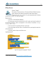
Projects in ScratchDuino consist of several scripts for different actors (see
Fig. 46).
39
Playground for
ScratchDuino.
Robokit
PROJECT
in ScratchDuino
ScratchDuino.Robokit
- Script 1
- Script …
- Script 2 (Stop)
Sprite …
- Script 1
- Script 2
- Script …
Stage
- Costume 1
- Costume 2
- Costume...
Fig. 46. The structure of a project in ScratchDuino.
Highlighted is the mandatory part.
The rest depends on the author’s design.
To describe the projects in ScratchDuino, the following pattern is used:
theme;
description;
playground;
requirements to meet;
description of the project progressing and/or explanations for the script;
the picture of the script.
40
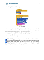
Basic Algorithms of ScratchDuino
The algorithms can be divided into three kinds as of their structure: linear,
branching, and loop. We’ll consider each of them below.
Linear algorithm is such one, for which all the commands are done one after
another and only once. Its script is a sequence of blocks, following from top to
bottom in the order of their performing.
In ScratchDuino, the virtual actor Cat always implements
a certain command in the same way. For example, the
command
wise, as shown on the right.
always causes the Cat to turn clock-
ScratchDuino.Robokit would turn right by 90° depending on:
the voltage that powers the rotation of the motors;
the quality of Bluetooth connection;
motor being in a working order;
the time specified for the motor to be on.
Theme: “Control by Arrow Keys”.
Description: Demonstration of robot’s motion, its speed, and its capability of
manoeuvering at the turns.
Playground: the tile “Sharp Turn” (from the set of tiles shown in
Fig. 40).
Requirements:
the Actor is ScratchDuino.Robokit;
the Actor’s motion to the left, to the right, forward (motor this way), and
backward (motor that way) is controlled by the “left arrow”, “right arrow”, “up
arrow”, and “down arrow” keys.
it is needed to determine how long the motor should work to make the
robot turn by 90° (by a right angle) to the right in case of different ways of connection (via USB and Bluetooth) and varied voltage (5–9V );
41
the script stops and the motor is switched off on pressing the space bar
of the keyboard.
Implementation
1.
Connect Arduino UNO via USB, following the instructions from the “Connecting ScratchDuino.Robokit” section.
2.
Use four commands of ScratchDuino.
Robokit, shown in Fig. 45.
3.
Build five scripts as shown in Fig. 52.
Each of these scripts is launched by its own
command in accordance with the block
that contains the condition to start.
4.
Run a trial launch of ScratchDuino.
Robokit. Make sure that it is controlled via the
keyboard correctly.
5.
Run a series of tests on the playground
made of one tile “Sharp Turn”. Vary the time
of motor being On as shown in Table 3 below.
Put the results into your own table.
6.
Save your script in ScratchDuino-Robot,
by selecting in the main menu File Save as
Scratch Projects folder filename.
7.
Disconnect ScratchDuino.Robokit from
the port. For that, right-click on the ScratchBoard panel. Select the command to disconnect the port. Remove the cable from the
Arduino UNO cartridge or from the USB port
at your PC.
8.
Fig. 47. Linear algorithm.
Scripts to control
ScratchDuino.Robokit
from the keyboard.
Plug in the Bluetooth adapter (Fig. 14).
9.
Connect the Arduino UNO cartridge to a power source, using the block
for connecting AA batteries.
42
10. Connect the Bluetooth2 (refer to the section “Installing the Software for
ScratchDuino.Robokit” of this Manual). When asked for a password, type 1234.
11. Check the Bluetooth port with the Device Manager (Fig. 18). Follow the
instruction from the section “Connecting”, with the jumpers in the Bluetooth
position.
12. Open the script you have saved before: File Open Scratch Projects
Folder filename. Run a trial launch of ScratchDuino.Robokit. Make sure that
it is controlled via the keyboard and Bluetooth.
13. Run a series of tests on the playground made of one basic tile “Sharp
Turn”, varying the time of motor being On as shown in Table 3. Put the results
into your own table.
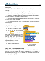
Table 3. Relation between the Time of ScratchDuino.Robokit Motor Being On
and the Turning Angle
Time (in seconds),
specified by the
block motor direction Right
When connected
When connected
via USB (5V)
via Bluetooth (7.6V3)
Number of the Turning
“right arrow” angle,
degrees
pressings
Number of the Turning
“right arrow” angle,
degrees
pressings
0,1
15
6
5
20
0,5
0,9
4
43
2
1
110
90
1
2
45
2
1
90
Conclusion: If ScratchDuino.Robokit (model 000242) is connected to the PC via
USB, the motor must be On for 2 seconds to turn right by 90°. If the same model is connected to the PC via Bluetooth and is powered by a voltage of 7.6V, the
motor must only be On for 0.9 seconds to turn right by 90°.
2
You can use the built-in Bluetooth adapter of your PC; if there is no such adapter, use the one shipped with
the kit.
3
For this test, a 7.6V lithium-polymer battery was used (depending on the state of charge, it gives a voltage of
6.6–8.4V).
43
When the power voltage increases, the rotation rate of the motor increases drastically. The success at a contest depends both on the script quality
and on the technical state of the Actor.
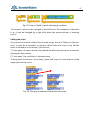
Loop algorithms. A loop is a series of commands to be repeated until a
specified condition becomes true. Thanks to the operators controlling the loop,
the script can be done much shorter. ScratchDuino provides the blocks for four
kinds of loops: unconditioned (endless); with a counter; with a pre-condition;
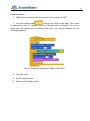
and with a post-condition (Fig. 48).
Fig. 48. Scratch blocks for loops.
Theme: “Getting around an Object”.
Description: Demonstration of the ScratchDuino.Robokit motion
when getting around an object. Explore the relation between the
time of motor being On and the covered distance. Use a virtual
actor to play a sound on the actions of ScratchDuino.Robokit.
Playground: any flat surface of a size 500×500 mm with an object in the middle
(of a size 120×120 mm) to be travelled around.
Requirements:
Actors: ScratchDuino.Robokit and a virtual actor able to play a sound of
“barking”;
the script starts to run on pressing the “up arrow” key;
on getting around the object, the ScratchDuino.Robokit must stop by itself when reaches the starting point (approximately);
each time the ScratchDuino.Robokit changes the direction of its motion,
the virtual actor “barks” like a dog;
the script stops and the motor is switched off on pressing the space bar
of the keyboard.
Implementation
1. Follow the instructions of the section “Connecting via USB”.
44
2. Use Fig. 49 to build the script.
Fig. 49. A loop.
3. It is easy to notice that getting around an object needs a series of
commands to be repeated: motor direction this way, motor on for __ secs,
motor direction left, motor on for __ secs, play sound Dog1.
4. By experiments, find the time (in seconds) that the actor needs to pass
one side of a polygon, if the connection to the PC is via USB.
5. Save the file of the project.
Before building your script, you need to enable the sound effect. In the
Sound tab, select the button Import and select the sound Dog1 in the
Animal folder. Then select the block play sound in the Sound group.
A drop-down list shows only the uploaded sounds (Sound tab).
ScratchDuino.Robokit has no audio system, and the command “play sound” is
to be done by virtual Actor.
45
Co-operation of the Sensors and the Motor
Touch Probe
We go on with the algorithms and start studying the sensors.
Branching algorithms. An algorithm is called branching if it has several options
to choose for a further action. The choice can be simple (in case of two alternative options) or complicated (when there are more than two options) (Fig. 50).
Fig. 50. A complicated choice.
The moment of a choice is called the branching point. Branching is one of the
three basic structures of algorithms (along with the linear flow of commands
and the loop). All the programming languages have special operators (or commands) — conditional operators, to implement an action depending on a stated condition. ScratchDuino has three conditional operators in its Control group:
complete branching (IF-THEN-ELSE), incomplete branching (IF-THEN), and
pause (WAIT UNTIL) (Fig. 51).
Fig. 51. Conditional operators in ScratchDuino.
Theme: “Getting around an Object 2”.
Description: ScratchDuino.Robokit, like in the previous project,
travels around an object. The motion starts on pressing the button (touch probe) by a human intervention as a “Start” command.
Playground: any flat surface of a size 500×500 mm with an object in the middle
(of a size 120×120 mm) to travel around.
46
Requirements:
Actors: ScratchDuino.Robokit and a virtual actor able to play a sound of
“barking”;
the script starts to run on pressing the “up arrow” key;
the motion is initiated by pressing the button of the touch probe;
on getting around the object, the ScratchDuino.Robokit must stop by itself when reaches the starting point (approximately);
each time the ScratchDuino.Robokit changes the direction of its motion,
the virtual actor “barks” like a dog;
the script stops and the motor is switched off on pressing the space bar
of the keyboard.
Implementation
1. Follow the instructions of the section “Connecting via USB”.
2. Use Fig. 52 to modify the script.
3. As you can see, the incomplete
branching
was added to the
ready script, with the condition to check
the value read by the touch probe. This
value is taken from the connected
ScratchDuino.Robokit. As per the
requirement, the script runs when the
button at the probe is pressed.
4. Test the script.
5. Save the file of the project.
Fig. 52. An algorithm
with branching.
How to “build” a block checking a condition
Fig. 52 shows the blocks checking a condition. Such block is “built” as follows:
you “drag”, one after another, the block IF-THEN (from the Control group), a
logical expression (from the Operators group), and the sensor value (from the
Sensing group) (see Fig. 53).
47
Fig. 53. How to “build” a block checking a condition.
The numeric value can be changed in the Edit field. The comparison character
(> or <) can be changed by a right click when the mouse pointer is hovering
over it.
Editing the script
If you need to remove a block from a ready script, the rule “Detach at the bottom” is used. As an example, to remove a block from the script in Fig. 54 (the
block is marked by a red arrow), you have to:
1) “tear away” the piece of the script below the block that you want to remove,
putting this piece aside;
2) “tear away” the said block in the same way;
3) bring back the former “torn away” piece and snap it to the bottom of the
upper piece of the script.
Fig. 54. The way to remove a block from the script.
48
Line Detector
Using one or more line detectors, ScratchDuino.Robokit is able to pass the
routes of tricky configurations. Before creating the projects for passing the
routes made of basic tiles (Fig. 40), we’ll consider the exercise of the line detector in a simple project “Edge of the Desk”.
Theme: “Edge of the Desk”.
Description: Demonstration of the ScratchDuino.Robokit motion,
when the robot detects the edge of a desk (a bench) using the
line detector and moves backwards to a safe distance. By experiments, find the maximal speed, at which the ScratchDuino.Robokit can approach the edge and manage to stop in proper time, using only the data given
by the line detector.
Playground: any flat surface with a sheer edge (a desk, a bench, a fat book etc.)
Requirements:
actors: ScratchDuino.Robokit and virtual actor able to play a “beeping”
sound;
the line detector is placed in the central socket of the
ScratchDuino.Robokit, which corresponds to a value of Analog3 variable;
the script starts to run on pressing the “up arrow” key;
on detecting the edge, ScratchDuino.Robokit stops and then moves
backwards for 1 second;
when the robot stops, the “beep” sound is played;
varying the time of the motor being On, find the maximal time interval
between the line detector checks, so that the robot can move as fast as possible without dropping from the desk.
49
Implementation
1. Follow the instructions of the section “Connecting via USB”.
2. Use the endless loop
to bring the robot to the edge. The motor
is switched on for 0.1 second, then the line detector is checked. For such a
short time, the robot covers a distance less than 1 cm, which excludes the risk
of dropping down.
Fig. 55. Script for the project “Edge of the Desk”.
3. Test the script.
4. Do the experiments.
5. Save the file of the project.
50
Light Sensor
Theme: “Night Work”.
Description: Demonstration of the ScratchDuino.Robokit motion,
when it finds a source of bright light using a light sensor and
approaches the light until it hits a vertical wall, then moves
backwards for 2 seconds and waits until the light fades. When another source
of bright light appears in the visibility zone (at twilight, ScratchDuino.Robokit
can “see” a source of bright light within 360°), ScratchDuino.Robokit moves to
the light again. Repeat several times until the script is stopped.
Playground: any flat surface shaped as a rectangle of a size 600×300 mm and
two sources of bright light, placed along the diagonal of the rectangle. It is possible to use one light source and relocate it as needed.
Requirements:
the Actor is ScratchDuino.Robokit;
the light sensors are put in the left and right sockets of
ScratchDuino.Robokit, which corresponds to the values of Analog0 and Analog4
variables; the touch probe is put in the central socket, which corresponds to a
value of Analog3 variable;
the script starts to run on pressing the “up arrow” key;
on finding a source of bright light, the Actor starts turning to this direction. When the direction is determined, the Actor approaches the light source;
when the touch probe hits an obstacle, the Actor stops and then moves
backwards for 2 seconds;
when the light is shining, the Actor stands still;
if the light fades, the Actor starts to “search” for another source of
bright light;
the script stops and the motor is switched off on pressing the space bar
of the keyboard.
51
Implementation4
1.
Follow the instructions of the section “Connecting via USB”.
2.
Testing the light sensors (see Table 1)
has shown that their sensitivity ranges differ
significantly, therefore an adjusting ratio of
1.27 is introduced.
Fig. 56. The line probe with
a bumper, and the blinders
for the light sensors.
3.
To determine the direction to the light
source more precisely, the ScratchDuino.
Robokit is slightly modified: between the
sensors, two “blinders” are inserted, which are
two cardboard pieces of a size 70×35 mm, put
on the left-hand and the right-hand sides of
the touch probe, i.e. between it and the light
sensors (Fig. 56).
4.
To increase the contact angle, a little
spring is fixed at the ending of the
touch probe as a “bumper”. It is a
useful modification of the touch
probe. The robot approaches the
light source at a small angle. The
touch probe triggers only with the
contact at 90°.
5.
With the modifications as
simple as these, the Actor performs
a rather complicated task. The
script is shown in Fig. 57.
Fig. 57. Script for the project “Night Work”
“Night work”.
4
See the video of working script at https://goo.gl/photos/tDwto2Q7s6U9ALi4A.
52
IR Eye Sensor
Theme: “Arena”.
Description: Demonstration of the ScratchDuino.Robokit motion,
when it detects an obstacle using IR Eye and travels along.
Playground: the arena, which is an area bounded with a hollow
cylinder as a “fence” of a 100-mm height.
Requirements:
the Actor is ScratchDuino.Robokit;
IR Eye sensors must be attached to the left, right, and central sockets of
ScratchDuino.Robokit, which corresponds to the values of variables Analog0,
Analog4, and Analog3;
the script starts on pressing the key “up arrow”;
the script stops and the motor is switched off on pressing the space bar
of the keyboard;
the Actor makes a lap around the arena.
Implementation5
Fig. 58. Script for the project “Arena”.
5
See the video of working script at https://goo.gl/photos/xGqDPZGMLJc77z7C9.
53
Promoting the Community of the Like-Minded
Each lucky owner of ScratchDuino.Robokit project constructor, be it a teacher
or parents, with time starts to feel some disappointment: what is next? As a
rule, their ideas of creating new projects quickly come to an end. However, if
there is a place where you can show off your projects and get them commented, or watch the ready projects of other people, your creativity gets a new impetus. The Internet communities are just about that, and they resemble the
thematic clubs where there are no differences caused by the age or the level of
skills. For Project ScratchDuino, the place for such socializing is the Wiki portal
wiki.scratchduino.com. In this section, we consider the recommendations for
new members of this community.
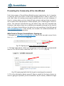
Wiki Portal of Project ScratchDuino: Signing up
1. Navigate to http://wiki.scratchduino.com and in the top-right corner find a
link Log in / Create an account (Fig. 59).
Fig. 59. Signing up at http://wiki.scratchduino.com.
2. The login page opens, where you are going to enter your login and password
later on. For the first time, select the link Create an account (Fig. 60).
Fig. 60. Login page (with the link to get to creating of an account).
3. Fill in the information about yourself. Keep in mind that the login of your account is going to represent you at the website. By this reason, choose the login
54
as your nickname that makes you recognizable. For example, if your name is
John Doe, your login can be John Doe, John, Doe etc. Avoid the impersonal
names. Click the Create account button.
Fig. 61. The fields to fill in at creating an account.
4. If all the fields are filled correctly, you will see a notification similar to shown
in Fig. 62:
Fig. 62. A notification about successful creation of an account.
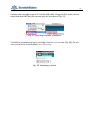
5. Check your Inbox and make sure that the message has not got into Junk Mail.
The sample body of the message sent to your email address is shown in Fig. 64.
Click the link within the message.
Fig. 63. The subject of the message in your Inbox folder.
55
Fig. 64. The body of the message in your Inbox folder.
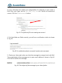
6. On clicking the link in the message, you get to the project website at a page
with the wording shown in Fig. 65.
Fig. 65. The page appearing after the confirmation of your email address.
7. Proceed with creating your personal page, where you can upload your projects for the sake of ideas exchange and discussions. Many of the members of
ScratchDuino Wiki portal have never met each other, so it would be nice to
place at the page a photo portrait of yours. It is advisable to choose the one
showing you in a good mood, as making the robotic projects is a pleasure after
all! The size of the photo file must not exceed 2MB. Accepted are file formats
PNG, GIF, JPG, JPEG.
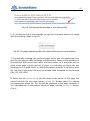
8. Select the link Upload file in the left menu of the portal. At the page that
opens find and click the upper button Upload file. Browse your PC to choose
the appropriate photo file. This file will be displayed at the page. However, it
isn’t uploaded yet! At the bottom left of the page, find the Upload file button.
Click it.
56
Fig. 66.The Upload file buttons.
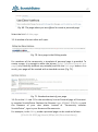
9. As a result, the page with the uploaded file will look
like shown in Fig. 67. Copy the title of the page. In our
example it is File:11-04-2015.jpg.
10. Now, create the proper page of ScratchDuino
community member at the portal http://wiki.
scratchduino.com. Take notice that your account
name at the top of the page is highlighted red
(Fig. 68). It means that the page has got a title, but
isn’t created yet! Click on the account name.
Fig. 67. The name of
the page that bears
your photo.
Fig. 68. From now on, your page has a title, but is not created so far.
11. You'll get to the page with the message shown in Fig. 69.
57
Fig. 69. The page where you are offered to create a personal page.
Select the link Edit this page.
12. A window of a text editor will open.
Fig. 70. Your page in the Editing mode.
For members of the community, a template of personal page is provided. To
create a page, it is enough to enter the phrase {{subst:Template:Personal user
page}} very carefully (without any mistake) and click the Save page button. As a
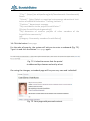
result, your page will be created with a standard content (Fig. 71).
Fig. 71. Standard content of your page.
13. Go to the Edit tab. Fill in the mandatory lines at Personal page of Community member ScratchDuino. Replace the filename Logo-1024be1-300x54.png with
the filename of your own photo. Instead of “Community member
ScratchDuino”, type in your Name and Surname etc.
For example, in the Editing mode a personal page can be made as follows:
[[File:11-04-2015.jpg|thumb|100px|left|Elena Vostrikova]]
58
'''City:''' [https://en.wikipedia.org/wiki/Novokuznetsk Novokuznetsk]
Russia
'''School:''' [http://ipknk.ru municipal autonomous educational institution of additional education "Training Institute"]
'''Position:''' department manager
'''My contribution to the prоject ScratchDuino:'''
[[Project ScratchDuinoLab gameship]]
'''My discussion of creative projects of other members of the
ScratchDuino community'''
null
[[Category: Community members ScratchDuino]]
14. Click the button Save page.
For the sake of security, the system will ask you to enter a codeword (Fig. 72).
Type it in and click the button Save page again.
Fig. 72. A check to ensure that the portal
is addressed by a human and not by a bot.
On saving the changes, a standard page will be your very own and individual!
Fig. 73. Your page with personal content.
59
Click on the category Community members ScratchDuino, and you’ll get to the
page with the list of those who have created their pages and are preparing (or
are ready) to upload their projects. Now you can explore the community members’ pages and participate in the discussions on completed projects.
60
wiki.scratchduino.com: Uploading a Project
If you have created a project that you think exciting and you are ready to share
it with the community, then send your brainchild to the annual ScratchDuino
Libre Robotics Festival.
At your personal page in the Editing mode, add a name of the page to place
your project at. For this, you need to type in the name adherent to following
conventions:
1) The name must begin with the word Project.
2) After a blank space, mention the nomination relevant to your project.
3) The name must be unique and not coinciding with the name of any other
project. To ensure this, go to [[Category: Projects]] and check if the name
is not used by anybody else.
An example of such a name follows:
*[[Project ScratchDuinoRobokit blackline]]
4) Click the button Save page!
Fig. 74. The page of project portfolio has got a name,
but hasn’t been created yet.
Click the newly-created link and go to the Editing mode for the new page.
61
Fig. 75. Editing mode for a new page.
For the Festival participants, the template is provided to make the deployment
of a project portfolio easy. To create the page, it would be enough to type in
(very carefully, without mistakes) the phrase {{subst:Template:Festival project
ScratchDuino}} and click the Save page button.
As a result, the portfolio of the project will be deployed.
Fig. 76. A template page for a project portfolio.
62
Next, it is important to fulfill all the sections of the portfolio. Below, a ready
portfolio (in editing mode) is shown.
== Name of author (s) of the project and the reference (s) of person
(s) on the page http://http://wiki.scratchduino.com /==
[[User:Elena Vostrikova]]
== Participant category ==
Not categorized
==Nomination to submit the project==
ScratchDuinoRoboKit
== Description of the project ==
Demonstration of the motion of ScratchDuino.Robokit that uses the
line probe mounted in the central socket (analog 3) to detect a black
line, and travels along the line.
Project Field: Made of the tiles “Straight Line” and “Smooth Turn”
==Link to download the project==
[https://goo.gl/GqWnOp Active link to a *.sb file]
[[Category: Project]]
[[Category: ScratchDuino 2016]]
Click the button Save page!
From now on, your project is available for the whole community. The comments can be read and written at the project page, at the Discussion tab.
63
Rules on Discussing the Projects at wiki.scratchduino.com
The Festival is not a contest but a live exchange of ideas, findings, and ready
projects, as well as a permanent search of the best ways to introduce the libre
robotics. That is why, along with the number and the quality of the projects uploaded, the Expert Group will consider also the number and the quality of the
discussions led by a participant.
The discussion is always a dialogue: one person puts questions and another
person answers. If somebody has left a question for you at the Discussion tab
(Fig. 77), or there are criticisms or ideas offered to make your project better, it
is considered a good practice to thank for the question and give a detailed answer, to agree with a criticism or retort against it, to consider and accept (decline) the suggestions.
Fig. 77. The Discussion tab
at the page of project portfolio.
To not reduce the discussion to just a mutual exchange of emoticons or rather
meaningless sentences like “Great!” or “ Cool!”, we would suggest a “3-2-1”
strategy. It means that you have to put THREE questions, give TWO criticisms,
and offer ONE improvement. An example of a discussion following such strategy is shown in Fig. 79. On completing your message, click the Your signature
and timestamp button. You will see a character string --~~~~. Then click the
Save the page button.
You should be nice and polite with the people, especially as you are a perfect
stranger for them. When discussing a project, avoid the harsh phrases like
“Your stuff is nonsense!” in favour of something like “This idea needs certain
refinement.” It is not easy to start developing a worthy project at once, and it is
important to encourage the newbies. A friendly word can lend them wings!
64
Fig. 78. An example of a discussion page
in Editing mode.
You might begin your questions with:
When? How? Where? Why?
Is it right to believe that … ?
What if … ?
Is it possible to … ?
At which line of the script … ?
etc.
The advisable introductory phrases for your comments might be as follows:
It would be better if …
On clicking ..., … point to a mistake that the author has not noticed)
It’s a pity that ... is missing
etc.
You should make your suggestions as if you are in the stead of the author.
There is always a way of getting the project better. We are looking for the best
solutions together, so any useful idea to help the author is welcomed.
65
Fig. 79. An example of a discussion page
in Read mode.
The Expert Group of the Festival does not deal with the anonymous messages! Having your message complete, always click the button Your signature and timestamp.
66
Information Sources for Project ScratchDuino
ScratchDuino official website
File server
ScratchDuino Wiki
ScratchDuino Group at Google+
ScratchDuino video channel at YouTube
Group at VKontakte social network
Personal blog of Yuriy Vinnitskiy
http://www.scratchduino.com/
http://files.scratchduino.ru/
http://wiki.scratchduino.com/
https://goo.gl/uVRm6D
https://goo.gl/Y5jDz8
http://vk.com/scratchduino
https://sc169.wordpress.com/
Russian-speaking help desk
[email protected]
67
Appendix
Statutes of ScratchDuino Libre Robotics Festival
1. General Provisions
All-Russia (International, in case of foreign participants) festival “ScratchDuino
Libre Robotics” hereinafter, the Festival) shall be held annually, in accordance
with the state policy concerning the development of educational robotics and
lifelong IT-education in the Russian Federation.
Founders of the Festival: JSC “Tyrnet” and partners.
The objectives of the Festival are:
generalization and promotion of the experience of applying the libre robotics;
introduction of libre robotics into the curriculums of primary and secondary educational institutions, as well as in the family form and for selfeducation.
Participants of the Festival: educators, students, and creative teams of adults
and children, ranked by their skills and education level.
2. The Organization of the Festival
2.1. The preparation and holding of the Festival shall be carried out by an Organizing Committee.
2.2. The Organizing Committee shall:
make a list of the Expert Group;
notify about the schedule, the procedure, and the results of the Festival;
examine the projects submitted to the Festival;
promote the best participants of the Festival.
3. The Content and the Procedure of the Festival
3.1. The Festival shall be held in 3 stages.
Stage 1— Grassroots (September–December):
the Festival participants are registering on the website
http://wiki.scratchduino.ru and uploading the portfolio of their festival projects;
68
the Festival participants study each other’s projects, make their comments, and put questions to the authors;
the participants put their applications into a self-registration sheet at a
page of the Festival website;
ScratchDuino Group at Google+ (https://goo.gl/uVRm6D) runs consultative workshops;
the information about the Festival is published by the mass media.
Stage 2— Expertise (January):
the Expert Group is working;
the best participants of the Festival are being chosen, ranked by educational level within the nominations.
Stage 3 — Final (February 7— International Day of Robotics)
the best participants of the Festival are announced and awarded.
3.2. The examination of the projects shall be made within two (or four, in case
of such kinds of projects) nominations, taking into account the educational
level:
ScratchDuino.Lab
ScratchDuino.Robokit
ScratchDuino.Lab (modification)
ScratchDuino.Robokit (modification)
3.3. The participants themselves shall upload their projects to the portal
http://wiki.scratchduino.com/ as a project portfolio, with mandatory indication of the participant category [[Category: Projects]]
[[Category: ScratchDuino 2016]]
3.4. The projects submitted shall have no feedback review of the Expert Group.
3.5. The names of the best participants of the Festival shall be placed at the
homepage of the Festival website.
4. Selection Criteria To Choose the Best Participants of the Festival
number and quality of the projects submitted;
number and quality of the discussions held by the participant on the projects of other people.
69
5. The Festival Schedule
5.1. The project portfolio is to be placed at http://wiki.scratchduino.com/
by ___ “____” 20__ .
5.2. The list of the best participants mentioning their awards is to be published
at the homepage of the Festival website on February 7 — International Day of
Robotics.
6. Awards for the Participants of the Festival
6.1. All the participants shall get the electronic certificates.
6.2. Based on the rating of their projects, the PARTICIPANTS, LAUREATES, and
WINNERS of the Festival shall be chosen, ranked by educational level within the
nominations.
User Manual
Elena A. Vostrikova, Cand.Sc. (Education),
Chief of Education Development Dept.
at Additional Vocational Training Institute, Novokuznetsk
[email protected]
Leonid S. Zakharov, programming engineer
with Kemerovo Region Department at the Russian Ministry of Interior,
Novokuznetsk
Ekaterina A. Lvova, engineering team leader of Project ScratchDuino,
St.Petersburg
[email protected]
ScratchDuino.Robokit
Translation by Elena Tolstyakova
Passed for printing: XX.XX.2015. 1000 copies.
JSC “Tyrnet” Reprographics Center
Medikov pr. 5/7, St.Petersburg, 197022 Russia