1
DEVELOPMENT OF VITAL SIGN (ECG) MONITORING SYSTEM USING PC
THOMAS LEONG TZE HSIUN
UNIVERSITI TEKNOLOGI MALAYSIA
PSZ 19:16 (Pind. 1/07)
UNIVERSITI TEKNOLOGI MALAYSIA
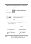
DECLARATION OF THESIS / UNDERGRADUATE PROJECT PAPER AND COPYRIGHT
Author’s full name :
THOMAS LEONG TZE HSIUN
Date of birth
:
6 JULY 1987
Title
:
DEVELOPMENT OF VITAL SIGN (ECG) MONITORING
Academic Session :
SYSTEM USING PC
2009/2010
I declare that this thesis is classified as :
√
CONFIDENTIAL
(Contains confidential information under the Official Secret
Act 1972)*
RESTRICTED
(Contains restricted information as specified by the
organisation where research was done)*
OPEN ACCESS
I agree that my thesis to be published as online open access
(full text)
I acknowledged that Universiti Teknologi Malaysia reserves the right as follows :
1. The thesis is the property of Universiti Teknologi Malaysia.
2. The Library of Universiti Teknologi Malaysia has the right to make copies for the purpose
of research only.
3. The Library has the right to make copies of the thesis for academic exchange.
Certified by :
SIGNATURE
870706 52 5933
SIGNATURE OF SUPERVISOR
EN. ISMAIL BIN ARIFFIN
(NEW IC NO.)
Date :
NOTES :
Date :
*
If the thesis is CONFIDENTIAL or RESTRICTED, please attach with the letter from
the organisation with period and reasons for confidentiality or restriction.
“I hereby declare that I have read this report and in
my opinion this report is sufficient in terms of scope and
quality for the award of the degree of Bachelor of Engineering
(Electrical-Electronics)”
Signature
:
Name
:
Date
:
Signature
:
Name
:
Date
:
En Ismail Ariffin
April 2010
Issoc Prof Ir. Dr. Ing Eko Supriyanto
April 2010
DEVELOPMENT OF VITAL SIGN (ECG) MONITORING SYSTEM USING PC
THOMAS LEONG TZE HSIUN
A report submitted in partial fulfilment of the
requirements for the award of the degree of
Bachelor of Engineering (Electrical-Electronics)
Faculty of Electrical Engineering
Universiti Teknologi Malaysia
April 2010
ii
I declare that this report entitled “Development of Vital Sign (ECG) Monitoring System
using PC” is the result of my own research except as cited in the references. The
report has not been accepted for any degree and is not concurrently submitted in
candidature of any other degree.
Signature
Name
Date
:
:
:
THOMAS LEONG TZE HSIUN
April 25, 2010
iii
Dedicated, in thankful appreciation for support, encouragement and understandings
to my beloved mother, father and sisters.
iv
ACKNOWLEDGEMENT
First and foremost, I would like to express my heartily gratitude to my project
supervisor, En Ismail Arrifin and my co-supervisor, Issoc Prof Ir. Dr. Ing Eko
Supriyanto for the advice, aid, guidance and enthusiasm given throughout the progress
of this project.
My appreciation also goes to my beloved family’s support, tolerant and
assistance because without them I might not able to make this so far. Thanks for
their love, encouragement and emotional supports that they had given to me.
Last but not least, my great appreciation dedicated to my friends, SEL
member’s batch 2006 and those who had contributed to the success of this project
which are not mentioned here.
Thomas Leong Tze Hsiun, UTM
v
ABSTRACT
Nowadays the number of patient who needs constant assistance has been
increased. One key point of all critical care for patient is the continuous monitoring
of their vital signs. Among these, the ECG signal is used for non-invasive diagnoses
of cardiovascular diseases. This ECG signal can be monitored by the doctors by using
medical monitoring. There are many types of medical monitoring. It depends on
the type of disease. Usually, a doctor needs to monitor his patient for long duration,
such as abnormal heart rate or rhythm (arrhythmia). Electrodes and medical device
are fitted to the patient in more than 24 hours while he or she is doing daily activities
including sleeping at night. The existed medical monitoring devices are wired restraint
and unable to transmit data to the doctor in real time. As a result, immediate action
cannot be taken by the doctor to the patient in an emergency case. As a conclusion, this
project proposes a development of vital sign (heart rate) monitoring system by using
PC to monitor the patient’s ECG signal. Besides an embedded GUI (Graphical User
Interface) is developed in the PC for displaying the ECG signal, perform automatic
heart rate calculation based on the ECG signal and teleconsultation purpose for medical
expert’s convenience to monitor patient’s health in remote location.
vi
ABSTRAK
Pada masa kini, bilangan pesakit yang memerlukan pengawasian semakin
bertambah. Isyarat yang paling penting and perlu diawasi adalah isyarat ECG,
denyutan jantung pesakit. Isyarat ini dapat diawasi oleh doktor dengan menggunakan
alat pegawasian. Terdapat banyak jenis alat pengawasian, ianya bergantung kepada
jenis penyakit. Biasanya, doktor perlu mengawasi pesakitnya pada suatu jangka masa
yang panjang. Elektrod dan alat pengawasian perlu sentiasa dipakai dan berada pada
badan pesakit dengan melebihi 24 jam semasa dia sedang membuat kerja sendiri
termasuk tidur pada waktu malam. Alat pengawasian yang terdapat sekarang adalah
dilengkapi dengan banyak wayar dan tidak dapat menghantar maklumat kepada doktor
dengan segera. Oleh itu, tindakan segera tidak dapat diambil sekiranya berlaku
sesuatu kemalangan atau berada dalam keadaan kecemasan. Kesimpulannya, projek
ini mencadangkan tentang pengawasian isyarat ECG (denyutan jantung) melalui
komputer. Selain itu, suatu GUI (Graphical User Interface) telah dipancangkan untuk
membekalkan isyarat ECG pesakit, mengira bilangan denyutan jantung pesakit secara
automatik dan dapat mengawasi kesihatan pesakit dari tempat yang jauh.
vii
TABLE OF CONTENTS
CHAPTER
TITLE
DECLARATION
DEDICATION
ACKNOWLEDGEMENT
ABSTRACT
ABSTRAK
TABLE OF CONTENTS
LIST OF TABLES
LIST OF FIGURES
LIST OF ABBREVIATIONS
LIST OF APPENDICES
PAGE
ii
iii
iv
v
vi
viii
ix
xi
xii
xiii
1
INTRODUCTION
1.1
Background
1.2
Problem Statement
1.3
Objectives
1.4
Scope
1.5
Work Flow
1.6
Gantt Chart
1.6.1
Gantt Chart Semester I
1.6.2
Gantt Chart Semester II
1.7
Work Breakdown
1.8
Block Diagram
1
1
2
3
3
3
5
5
5
6
7
2
LITERATURE REVIEW
2.1
Telemedicine
2.2
Telemedicine Goals
2.3
Telemedicine VS Telehealth
2.4
Telemedicine Concepts
2.5
Current Situation of Telemedicine
9
9
9
10
11
12
viii
2.6
2.7
2.8
2.9
2.10
2.11
Electrocardiogram (ECG)
ECG Interpretation
ECG Electrodes
MDIZ and MDIZB
Microsoft Visual Studio
Visual Studio .NET
12
13
16
19
21
22
3
DESIGN AND IMPLEMENTATION
3.1
Design Specification
3.2
System Overview
3.3
Hardware
3.4
Software
3.5
Graphical User Interface (GUI)
3.6
Software Architecture
3.7
Algorithm
3.8
User Manual
23
23
25
25
25
26
28
29
34
4
RESULTS AND ANALYSIS
4.1
Tele-ECG Server GUI Testing
4.2
Tele-ECG Client GUI Testing
4.3
ECG Signal Displaying
4.4
Teleconsultation
4.5
Optimization
36
36
40
41
45
51
5
CONCLUSION AND RECOMMENDATION
5.1
Conclusion
5.2
Novelty
5.3
Limitation
5.4
Recommendation
52
52
52
52
53
REFERENCES
APPENDICES A – B
54
56 – 64
ix
LIST OF TABLES
TABLE NO.
TITLE
PAGE
2.1
2.2
2.3
2.4
2.5
Telemedicine VS Telehealth
ECG waveform
Electrodes Positions
MDIZ Characteristic
MDIZB Characteristic
10
14
19
19
20
3.1
Design Specification
24
x
LIST OF FIGURES
FIGURE NO.
TITLE
PAGE
1.1
1.2
1.3
1.4
1.5
Work Flow
Gantt Chart Semester I
Gantt Chart Semester II
Work Breakdown
Block Diagram
4
5
6
7
8
2.1
2.2
2.3
2.4
2.5
2.6
2.7
2.8
2.9
2.10
The normal ECG waveform
Normal sinus rhythm
Sinus tachycardia
Sinus bradycardia
ECG electrodes
Electrodes positions
Block diagram of MDIZ
Data frame of MDIZ
Block diagram of MDIZB
Data frame of MDIZB
13
15
16
17
17
18
20
20
21
21
3.1
3.2
3.3
3.4
3.5
3.6
3.7
3.8
3.9
3.10
3.11
3.12
3.13
System Overview
Tele-ECG Server GUI
Tele-ECG Client GUI (for medical expert)
Tele-ECG Client GUI (for client)
Software algorithm
Hub Setting
Access control
Edit username / password
New connection
Sending an alert message
Chat
Call requested
Local camera
25
26
27
27
28
29
30
30
31
32
32
33
33
xi
3.14
Remote camera
34
4.1
4.2
4.3
4.4
4.5
4.6
4.7
4.8
4.9
4.10
4.11
4.12
4.13
4.14
4.15
4.16
4.17
4.18
4.19
4.20
4.21
4.22
4.23
Tele-ECG Server
Checking IP address
Add Users
Enter username and password
Adding 2 Users
No encryption
Symmetric encryption
Asymmetric encryption
Connect to Server (medical expert)
Connect to Server (client)
Jacky is connected
Thomas is connected
ECG signal display (sinus bradycardia
ECG signal display (sinus rhythm
ECG signal display (sinus tachycardia
Sending alert message
Receiving alert message
Chatting
Calling
Receiving call request
Video-conferencing (medical expert)
Video-conferencing (client)
End call
36
37
37
38
38
39
39
40
40
41
41
42
43
44
45
46
47
47
48
48
49
50
50
xii
LIST OF ABBREVIATIONS
ECG
-
Electrocardiogram
GUI
-
Graphical User Interface
PC
-
Personal Computer
Wi-Fi
-
Wireless Fidelity
IP
-
Internet Protocol
LAN
-
Local Area Network
MDIZ
-
Medical Data Interface Zigbee
MDIZB
-
Medical Data Interface Zigbee Bluetooth
VB
-
Visual Basic
bpm
-
beat per second
xiii
LIST OF APPENDICES
APPENDIX NO.
A
B
TITLE
TELE-ECG SERVER
TELE-ECG CLIENT
PAGE
56
64
CHAPTER 1
INTRODUCTION
This chapter gives an overview of the whole project, starting with the project
background and problem statement, followed by the project objectives, scopes, and
methodology.
1.1
Background
According to a World Health Organization (WHO) estimate, cardiovascular
disease kills almost seventeen million people around the world each year, with around
twenty million people at a risk of sudden heart failure [1]. Some of these lives can
often be saved if quick care and cardiac surgery are provided within the so-called
golden hour. Therefore, patients who are at risk require that their cardiac health
to be monitored frequently whether they are indoors or outdoors so that emergency
action can be taken if problems arise [2]. Telemedicine is widely considered to
be part of the future of the modern practice of medicine. It is gaining more
momentum as a new approach for patients surveillance outside of hospitals (at home)
to encourage public safety and to facilitate early diagnosis, treatment, and increased
convenience. Defined as the ”use of advanced telecommunication technologies or
information technologies to exchange health information and provide health care
services across geographic, time, social, and cultural barriers, telemedicine is currently
being used by doctors, physicians, hospitals, and other healthcare providers around
the world [3]. Telemedicine provides a medical care by expert to any place where
patient is needed in emergency. Telemedicine has been introduced for more than 30
years ago, when telephone and fax machines were used as first telecommunication
system. Nowadays, telemedicine applications have been implemented over wired
and wireless communication technologies. Telemedicine applications reflect the
spectrum of clinical specialties and subspecialties found in conventional clinical
2
medicine. Besides that, telemedicine has been applied in practical education. Hence,
telemedicine is represented in the vast majority of medical specialties although the
stages of development and maturity vary substantially by specialty [4]. In addition,
health telematics applications is enabling the availability of expert medical care and
exploiting the provision of health-care services at rural health centres, ambulance
vehicles, ships, trains, and airplanes, as well as for home monitoring. With this wide
range of technologies available, telemedicine programs are no longer about proving
that telemedicine works but are about choosing the right communication mode to
deploy a cost-effective telemedicine network.
Currently ECG (Electrocardiograph) monitoring is the most widely used
technique for providing ambulatory cardiac monitoring for capturing rhythm
disturbances. Traditional ECG monitor can record up to 24 hours of ECG signals,
and the recorded data is subsequently retrieved and analysed by a clinician. Due to
the short duration involved and the unknown context within which the ECG signal
is captured, reliable interpretation of the recorded data is always a challenge [5].
Electrical signals from the heart characteristically precede the normal mechanical
function and monitoring of these signals has the great clinical significant and it is
very valuable for the experts or physician to determine type of diagnosis. However,
the accurate ECG interpretation is essentially required in order to evaluate the valuable
information inside the ECG signal.
1.2
Problem Statement
Current type of medical devices for vital sign monitoring use very expensive
components and not design for multi patients. Consequently, patients are unaffordable
to buy that particular medical monitoring device. Besides that, some of the monitoring
devices are wire restraint. It is not practice for patient’s mobility. Moreover, some
of them do not have connection to communication network. It causes data from the
medical devices are not able to be transferred through the network to provide fast
health service. Apart from that, current medical monitoring devices just record the
data, do not transmit the data in real time. Thus it causes the immediate action cannot
be taken if abnormality is found.
3
1.3
Objectives
The main objective of this project is to develop a software application for
wireless intensive ECG monitoring system. Besides that, a development on ECG
monitoring system with teleconsultation purpose is implemented. In another say, a
graphical user interface (GUI) will be developed to carry out the whole process by
displaying the ECG signal in real time, calculation of patient’s heart rate automatically
and able to perform teleconsultation by video-conferencing in real time (sending live
audio and live video information as well as chatting message) between medical experts
and clients.
1.4
Scope
Basically, my project will focus on the setup for software configuration to
capture the ECG data by using a low cost Medical Data Interface Zigbee (MDIZ) and
Medical Data Interface Zigbee Bluetooth (MDIZB) by using Zigbee and Bluetooth
wireless connection. Then will concentrate on the development of a GUI to display
the signal, heart rate calculation and then communicate with other same GUI in other
PC via LAN or wireless network. All of these tasks will be done by using Microsoft
Visual Studio 2008 and Visual Basic programming language. In additions, the ECG
used is type of 3-leads selectable ECG.
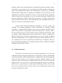
1.5
Work Flow
The work flow of the project’s activities was divided into different stages as
shown in the flow diagram below. Firstly, the project requires a literature study
on basic analysis of ECG signal. Then will proceed to the study of Visual Basic
programming language by using Microsoft Visual Studio 2008. After that, a study
on using MDIZ device and MDIZB device will be carry out. Then experiments on
ECG signal capturing and transmitting from ECG simulator to MDIZ to MDIZB and
then display it on the GUI that developed in the PC will be tested. Next, a GUI will
be developed for monitoring purpose and heart rate calculation. Finally a secure
communication network for teleconsultation purpose is developed for chatting and
webcam application.
4
Figure 1.1: Work Flow
5
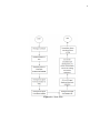
1.6
1.6.1
Gantt Chart
Gantt Chart Semester I
Based on the project’s proposal, my projects activities will be divided into
several important milestones where the details are shown in Gantt chart below:
Figure 1.2: Gantt Chart Semester I
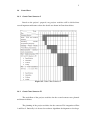
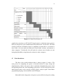
1.6.2
Gantt Chart Semester II
The work flow of the projects activities for the second semester was planned
and shown in below:
The planning of the project activities for the semester II is integration of Part
1 and Part 2. Basically it is focused on software algorithm development to develop a
6
Figure 1.3: Gantt Chart Semester II
graphical user interfaces or GUI for ECG signal analysis, calculation for the patient’s
heart rate and private secure communication network between 2 or more PCs. The final
developed software will further convert as standalone execution file or .exe format so
that it able to be run outside the Microsoft Visual Studio software environment or
others computer. Undoubtedly, this will make the software more friendly user and
having high flexibility to implement the software in other computers.
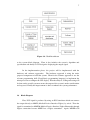
1.7
Work Breakdown
The flow of the work breakdown chart is shown at figure 1.2 above. The
main process in completing the project is basically divided as study, design and
implementation. Study is the process that is continuous throughout the project, from
the beginning till the end. At the beginning of the project, a lot of study has been done
which include study on the concepts of ECG signals, analysis signal, Visual Basic
programming language, microcontroller and GUI display.
Meanwhile in the design phase, the project system will be developed according
7
Figure 1.4: Work Breakdown
to the system block diagram. Then it also includes the system’s algorithm and
specification and finally is GUI design for displaying the output signal.
In the implementation phase, the project will be implemented with the
hardware and software approaches. The hardware approach is using the entire
prepared component to build the system. Then for the software approach is use the
relevant programming skill (Visual Basic programming language) to implement the
microprocessor to configure the GUI display. Then the analysis, coding and testing will
be done on the overall system to ensure the output of the system is under consideration
and expected. Finally the improvement is done to enhance the system performance.
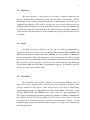
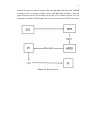
1.8
Block Diagram
First, ECG signal is produced by using an ECG simulator which can connect
the output directly to MDIZ (Medical Device Interface Zigbee) by wired. Then the
signal is transmitted to MDIZB (Medical Device Interface Zigbee Bluetooth) through
Zigbee connection because MDIZ has a Zigbee transmitter. Again, MDIZB will
8
transmit the signal to personal computer (PC) through Bluetooth connection. MDIZB
is unique because it contains a Zigbee receiver and Bluetooth transmitter. Then the
signal will display in the GUI developed on the PC screen. Finally, other PC also can
communicate with this GUI through LAN (Local Area Network) or Wi-Fi connection.
Figure 1.5: Block Diagram
CHAPTER 2
LITERATURE REVIEW
In this chapter, a review in knowledge of telemedicine and the electricity of the
heart or more commonly called electrocardiogram (ECG) will be look over. Besides,
Microsoft Visual Basic programming language will also be furthered discussed in this
chapter.
2.1
Telemedicine
What is telemedicine? Telemedicine is a branch of e-health that uses
communication networks or information technologies (IT) for delivery of healthcare
services and medical education from one geographical location to another. It is
deployed to cope with issues like uneven distribution and shortage of infrastructural
and human resources [6]. In other ways, telemedicine may be as simple as two health
professionals discussing a case related to health care over the telephone, or as complex
as using satellite technology and video-conferencing equipment to conduct a real-time
consultation between medical specialists in two different countries [7].
2.2
Telemedicine Goals
Concomitant advances in information technology and medical technology have
led to the increasing focus, development and use of telemedicine systems and services
around the globe, particularly in developed countries. The goals of these systems are:
•
increase the accessibility of and to caregivers
10
•
increase the quality and continuity of care to patients as well as the person around
us
•
increase the focus or awareness on preventive medicine through early
intervention. There is no meaning in comparing
•
reduce the overall cost of healthcare, help the poor patient
•
education and training purpose
•
provide services to remote areas in case of natural calamities, disasters and
military and space operations
•
remote monitoring or telemonitoring
Telemedicine has a very big relationship with telemonitoring. Telemonitoring
is the remote monitoring of patients, including the use of audio, video, and other
telecommunications networks and electronic information processing technologies
to monitor patient status at a distance. Telemonitoring is still overshadowed by
telediagnosis and teleconsulting. A more restrictive term used for telemonitoring is
biotelemetry, which consists of the transmission of biologic or physiologic data from a
remote location to another location for data interpretation, further analysis and decision
making.
2.3
Telemedicine VS Telehealth
Telemedicine is always used interchangeably with telehealth in common usage;
however they are not same. The table below summarizes the salient features of both.
Telemedicine
Table 2.1: Telemedicine VS Telehealth
Telehealth
Teleradiology
Patient records
Telepathodogy
Disease Management Information access
Teledermatology
Remote monitoring
Telepsychiatry
Patient compliance
Focus on discipline / technology Billing access and focus on Patient
11
2.4
Telemedicine Concepts
Telemedicine is practised on the basis of two concepts: real time (synchronous)
and store-and-forward (asynchronous).
Real Time Telemedicine (synchronous) is referred to as two way interactive
television (IATV). It another meaning, it can be as simple as telephone calls or as
complex as sophisticate virtual reality (VR) robotic surgery or tele-surgery. In it
providers/patients at different locations interact with each other using communication
technology in the form of audiovisual and wireless or microwave signals. Apart from
video-conferencing, peripheral sensing devices can also be attached to the patient
to aid in interactive examination. Besides that, it can also be used for long term
monitoring for home care patients. In fact, due to the high cost constraints, quality
and continuity of care issues, mal-distribution of physicians in different geographic
regions and scarcity of the same, remote home care of chronically ill patients and
of long term care patients, is the fastest emerging use of telemedicine. Specialities
for which it is used most frequent are psychiatry, internal medicine, rehabilitation,
cardiology, paediatrics, obstetrics and gynaecology, neurology.
Store and Forward (asynchronous) technology involves acquiring medical data
(images, bio-signals) and transmitting this data to a medical specialist for consultation,
evaluation or other related purposes. It does not require simultaneous communication
between both persons in real time. Tele-radiology and tele-dermatology is the fastest
emerging branches that use such kind of services. Overall radiology, pathology and
dermatology are most tending for utilizing this mechanism.
These basic telemedicine technologies as mentioned previously are utilized
for providing various health care services that spawns numerous specialties and can
be broadly categorized as telehome Home Health Care, telepsychiarty, teleradiology,
general telemedicine, telecardiology, telemedicine consulting (teleconsultation),
teledermatology, emergency telemedicine, telepathology, teledentistry, telesurgery,
telediagnostic, telemonitoring, telecare and teleeducation. Among these specialties,
teleconsultation is one of the most significant applications as it uses multimedia
telecommunication through networks for medical consultation. It can either use
ordinary telephone, email, or video-conferencing equipments. Real-time consultations
use the video-conferencing technology and permit the interaction and communication
between medical experts and clients [8].
12
2.5
Current Situation of Telemedicine
Telemedicine is a growing field which has a high potential for improving
accessibility to services, quality and continuity of care and significant savings in
the overall cost of healthcare. However the use of telemedicine applications has
not spread as extensively as other as other commonly used engineering techniques,
such as medical imaging [9]. Although telemedicine applications have proliferated in
recent years, their diffusion has remained low in terms of the volume of consultations
especially in Malaysia. This is not because telemedicine is less important but
because supporting technologies have been traditionally costly, institutionalized
and less pervasive and less capable in terms of data transfer speed and quality.
They need to develop technically feasible, medically valid, reimbursable, and
institutionally supported applications in order to justify the value of telemedicine and
engender consistent and frequent use by medical experts or physicians [10]. Fixed
communication network has been used in different telemedicine setup for some years
and it has shown its values, whereas wireless technologies within telemedicine have
been developed only in the last few years. One of the sole decisive factors that will
cause a telemedicine system successful, in urban and rural areas, is the application
of modern communication technology for information exchange between a homecare
patient and the medical specialists providing care [11].
2.6
Electrocardiogram (ECG)
Electrocardiogram (ECG) is the recording of the heart’s electrical activity over
time via skin electrodes. The deviations in the normal electrical patterns indicate
various cardiac disorders and abnormalities. Cardiac cells, in the normal state are
electrically polarized. Their inner sides are negatively charged relative to their outer
sides. These cardiac cells can lose their normal negativity through a process called
depolarization, which is the fundamental electrical activity of the heart. This process is
propagated from cell to cell, producing a wave of depolarization that can be transmitted
across the entire heart. This wave of depolarization produces a flow of electric current
and it can be detected by keeping the electrodes on the surface of the body (skin).
Once the depolarization is complete, the cardiac cells are able to restore their normal
polarity by another process named re-polarization. This process also sensed by the
electrodes [12]. In additions, ECG simulator is a tool that simulates or recreates an
ECG.
13
2.7
ECG Interpretation
The ECG records the electrical activity of the heart over time, where each heart
beat is displayed as a series of electrical waves characterized by peaks and valleys.
Any ECG gives two kinds of information. First, the duration of the electrical wave
is crossing the heart which in turn decides whether the electrical activity is normal or
slow or irregular while the second is the amount of electrical activity passing through
the heart muscle which enables to find whether the parts of the heart are too large or
overworked. Normally, the frequency range of an ECG signal is of 0.05C100 Hz and
its dynamic range of 1C10 mV.
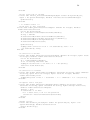
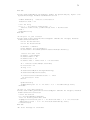
Figure 2.1: The normal ECG waveform
The ECG signal is normally characterized by five peaks and valleys labeled by
the letters P, Q, R, S, T. The performance of ECG analyzing system depends mainly
on the accurate and reliable detection of the QRS complex, as well as T- and P-waves.
The P-wave represents the activation of the upper chambers of the heart, the atria,
while the QRS complex and T-wave represent the excitation of the ventricles or the
lower chamber of the heart. The detection of the QRS complex is the most important
part in automatic ECG signal analysis. Once the QRS complex has been identified a
14
more detailed examination of ECG signal including the heart rate, the ST segment and
others can be performed.
In the normal sinus rhythm (normal state of the heart) the P-R interval is in
the range of 0.12 to 0.2 seconds. The QRS interval is from 0.04 to 0.12 seconds.
The Q-T interval is less than 0.42 seconds and the normal rate of the heart beat is
from 60 to 100 beats per minute. So, from the recorded shape of the ECG, we can
conclude whether the heart activity is normal or abnormal. The electrocardiogram is a
graphic recording or display of the time variant voltages produced by the myocardium
during the cardiac cycle. The P-, QRS- and T-waves reflect the rhythmic electrical
depolarization and repolarization of the myocardium associated with the contractions
of the atria and ventricles and very useful in diagnosing various abnormalities and
conditions associated with the heart [13].
Table 2.2: ECG waveform
Amplitude
Duration
P-wave - 0.25 mV
P-R interval: 0.12 to 0.20 ss
R-wave - 1.60 mV
Q-T interval: 0.35 to 0.44 s
Q-wave - 25% R wave
S-T interval: 0.05 to 0.15 s
T-wave - 0.1 to 0.5 mV P-wave interval: 0.11 s
QRS interval: 0.09 s
The normal value of heart beat lies in the range of 60 to 100 beats per minute,
named as sinus rhythm (Normal heart). A slower rate than this is called bradycardia
(Slow heart), in which the heart rate value is lower than 60 beats per minute while a
higher rate is called tachycardia (Fast heart) in which the heart rate value is exceed 100
beats per minute. If the cycles are not evenly spaced, an arrhythmia may be indicated.
If the P-R interval is greater than 0.2 seconds, it may suggest blockage of the AV node.
•
Certain disorders, involving heart valves cannot be diagnosed from ECG. Other
diagnostic techniques such as angiography and echocardiography can provide
information not available in ECG.
15
•
Each action potential in the heart originates near the top of the right atrium at a
point called the pacemaker or sinoatrial (SA) node.
•
The wave generated by action potential, terminates at a point near the center of
the heart, called the atrioventricular (AV) node.
The horizontal segment of this waveform preceding the P-wave is indicated as
the baseline or the isopotential line. The P-wave represents depolarization of the atrial
musculature and the QRS complex is the combined result of the repolarization of the
atria and depolarization of the ventricles, which occur almost simultaneously. The Twave is the wave of ventricular repolarization. Consequently, the duration amplitude
and morphology of the QRS complex is useful in diagnosing cardiac arrhythmias,
conduction abnormalities, ventricular hypertrophy, myocardial infection and other
disease or abnormalities [14].
Figure 2.2: Normal sinus rhythm
16
Figure 2.3: Sinus tachycardia
2.8
ECG Electrodes
Basically, there are three of these leads, I, II and III.
Lead I
is between the right arm and left arm electrodes, the left arm being positive
Lead II
is between the right arm and left leg electrodes, the left leg being positive
Lead III
is between the left arm and left leg electrodes, the left leg again being
positive
17
Figure 2.4: Sinus bradycardia
Figure 2.5: ECG electrodes
18
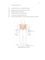
Chest Electrode Placement:
V1
Fourth intercostal space to the right of the sternum
V2
Fourth intercostal space to the Left of the sternum
V3
Directly between leads V2 and V4
V4
Fifth intercostal space at midclavicular line
V5
Level with V4 at left anterior axillary line
V6
with V5 at left midaxillary line. (Directly under the midpoint of the armpit)
Figure 2.6: Electrodes positions
19
Table 2.3: Electrodes Positions
Chest Leads View
2.9
V1 and V2
Right Ventricle
V3 and V4
Septum / Lateral Left Ventricle
V5 and V6
Anterior / Lateral Left Ventricle
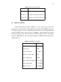
MDIZ and MDIZB
Medical Data Interface Zigbee (MDIZ) is a device which receives data from
medical device and transmits it out through Zigbee network, while MDIZB coordinates
the Zigbee network as well as communicates with other devices through Bluetooth
network. MDIZ is able to send data up to 115200 bps. The bandwidth is more than
enough for vital sign data. The network has a PAN ID to differ with the other Zigbee
networks. MDIZB has the same operational frequency as MDIZ, but the modulation is
slightly different.
Table 2.4: MDIZ Characteristic
Parameter
Value
gain transmitter
1 dBi
gain receiver
1dBi
receiver sensitivity
-92 dBm
indoor coverage range
30m
line of sight range
100m
Zigbee channel frequency 2.411 GHz
Zigbee bandwidth
1.359 MHz
Zigbee data rate
115200bps
20
Table 2.5: MDIZB Characteristic
Parameter
Value
gain transmitter
1 dBi
gain receiver
1dBi
average power
-89 dBm
line of sight range
100m
Bluetooth channel frequency 2.411 GHz
Bluetooth bandwidth
1.359 GHz
Bluetooth data rate
723300bps
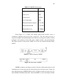
From Figure 2.7, it shows that analog signal from medical sensor is
conditioned, digitized and processed by a processor. The data from processor is
converted to Zigbee and then transmitted out. The data is arranged in a frame as shown
in Figure 2.8 It consists of device ID, status, length of frame, data and checksum.
The Zigbee module is bidirectional. MDIZ can receive the command through Zigbee
module.
Figure 2.7: Block diagram of MDIZ
Figure 2.8: Data frame of MDIZ
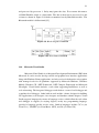
MDIZB coordinates the Zigbee network. It decides which medical device will
communicate to in that time and give them priority based on their status. Figure 2.9
shows block diagram of MDIZB which consists of Zigbee module, two processors, Dlatch, SRAM, and Bluetooth module. Data from MDIz is received by Zigbee module
21
and processed by processor 1. Delay may ignore the data. To overcome this matter,
a 256kb SRAM is added as a data buffer. The data is then sent to processor 2 to add
a frame as shown in Figure 2.10 before transmitted out by Bluetooth module. The
Bluetooth module is bidirectional [15].
Figure 2.9: Block diagram of MDIZB
Figure 2.10: Data frame of MDIZB
2.10
Microsoft Visual Studio
Microsoft Visual Studio is an Integrated Development Environment (IDE) from
Microsoft. It can be used to develop console and graphical user interface applications
along with Windows Forms applications, and web services in both native code together
with managed code for all platforms supported by Microsoft Windows, Windows
Mobile, Windows CE, .NET Framework, .NET Compact Framework and Microsoft
Silverlight. Visual Studio includes a code editor supporting IntelliSense as well as
code refactoring. The integrated debugger works both as a source-level debugger and
a machine-level debugger. Other built-in tools include a forms designer for building
GUI applications, web designer, class designer, and database schema designer. Visual
Studio supports languages by means of language services, which allow the code editor
and debugger to support (to varying degrees) nearly any programming language,
provided a language-specific service exists. Built-in languages include C/C++ (via
Visual C++), VB.NET (via Visual Basic .NET), and C# (via Visual C#).
22
2.11
Visual Studio .NET
Visual Basic .NET (VB.NET) is an object-oriented computer programming
language that can be viewed as an evolution of Microsoft’s Visual Basic (VB)
which is generally implemented on the Microsoft .NET Framework. Microsoft
currently supplies Visual Basic Express Edition free of charge. Visual Basic (VB) is
the third-generation event-driven programming language and integrated development
environment (IDE) from Microsoft for its COM programming model. VB is also
considered a relatively easy to learn and use programming language, because of its
graphical development features and BASIC heritage.
CHAPTER 3
DESIGN AND IMPLEMENTATION
This chapter described the design methodology for the ECG signal capturing
by using PC. The design system will be described according to the block diagram,
hardware and software approach.
3.1
Design Specification
24
Table 3.1: Design Specification
Specification
Detail
Dimension
MDIZ: 4.5 X 2.56 X 1.18
MDIZB: 6 X 4.65 X 2.5
Power
MDIZ: Battery: 9V
MDIZB: Built-in LiPo rechargeable 11.1V
Performance
Display: PC
Trace: 3-leads selectable ECG
Parameter: Heart Rate (BPM)
Feature
ECG display in real time
Heart rate calculation automatically
Teleconsultation: Instant alert and chat message sending,
live video-conferencing using webcam
Communication Zigbee, Bluetooth, LAN, Wi-Fi
25
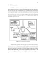
3.2
System Overview
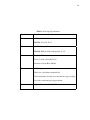
Figure 3.1: System Overview
3.3
Hardware
The hardware approach for this project included ECG simulator, medical
data interface (MDIZ and MDIZB), both medical data interface devices contain
microcontroller ATMEGA162-16PU and the implementation of the GUI display.
General hardware component included Zigbee transmitter, Zigbee receiver, Bluetooth,
2 microcontrollers type ATMEGA162-16PU.
3.4
Software
The software approach for this project included the coding design for
Microcontroller ATMEGA162-16PU and the GUI development. General software
component used in this project included Microsoft Visual Studio 2008 and Microsoft
Visual Basic .NET.
26
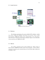
3.5
Graphical User Interface (GUI)
The GUI is developed using Microsoft Visual Studio 2008 and Microsoft
Visual Basic .NET. The development of the GUI includes on how to read data from
the microcontroller ATMEGA162-16PU and displayed it in the GUI. There are two
main GUI, first is Tele-ECG Server, act as a server while second GUI named TeleECG Client act as client to that server and also includes the plotting graph of the
ECG signal in real time, calculation of patient’s heart rate automatically, chatting and
webcam interface.
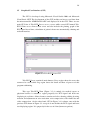
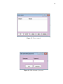
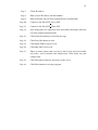
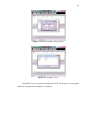
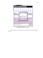
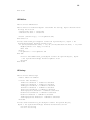
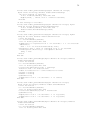
Figure 3.2: Tele-ECG Server GUI
Tele-ECG Server contains 6 main buttons, Peers region shows the users that
connected to server while Log region shows the detail and flow of process of this
program with timing.
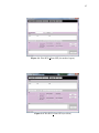
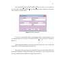
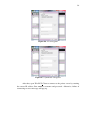
This type Tele-ECG Client (Figure 3.3) is mainly for medical expert or
physician because it contains a region purposely for ECG signal and heart rate
displaying in real time. Others features contain send alert, chatting, talking by using
webcam, and adjustment on voice activation, voice compression, video frame rate and
video compression. On the other hand, GUI in Figure 3.4 is almost same with the
previous GUI shown in Figure 3.3 except it do not include the ECG signal and heart
rate displaying region. It is purposely for the use of client (homecare patient).
27
Figure 3.3: Tele-ECG Client GUI (for medical expert)
Figure 3.4: Tele-ECG Client GUI (for client)
28
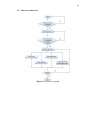
3.6
Software Architecture
Figure 3.5: Software algorithm
29
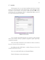
3.7
Algorithm
In this program, there are several major algorithms that had been developed
and each of it will perform their specific functional tasks. In Tele-ECG Server GUI,
Start button is used to initialize a server network. While Stop button is used to stop
and disconnect the server immediately. There is a Setting button which is used to set
the security setting and other useful options.
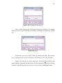
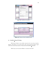
Figure 3.6: Hub Setting
Users can either using default mode that is no encryption or using encryption
mode by key in shared secret keys (symmetric encryption) or public / private keys
(asymmetric encryption).
Next is Users button. Its function is used to add the users whose can connect to
this server. Of course, it also can remove user.
By clicking the Add or Edit button, a window will pop up to key in the
username and password of the user.
Next, user can check the IP address by clicking My IP button.
Finally is Exit button to exit the whole program.
30
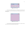
Figure 3.7: Access control
Figure 3.8: Edit username / password
31
Once Tele-ECG Server is ON, Tele-ECG Client can start to use to connect to
the server that created by Tele-ECG Server. By clicking Connect button, it will pop up
a new window as shown below.
Figure 3.9: New connection
User has to enter the IP address, port number while username and password
are optional unless user already set it in the Tele-ECG Server previously as shown in
Figure 3.7.
While Disconnect button is disconnect the user from server. Next is the most
important part, ECG signal display in picture box.
Then turn to the interesting part in this GUI, that is teleconsultation GUI. First
is the alert notification sending by clicking Send Alert button. User can type the alert
message and then click Send button to single user or all user
32
Figure 3.10: Sending an alert message
Next is chatting function by clicking Start Chat button. It will pop out a chatting
window for user to type the message and click the Send button to send message to other
user.
Figure 3.11: Chat
Besides that, user also can talk to others by clicking Begin Talk. This function
is very amazing because user can speak and view the other user by using webcam.
Figure 3.12 will pop up at the other user’s Tele-ECG Client GUI to ask
permission for a call requested from the user. If Accept button is clicked, they can start
to talk to each other but other user also can reject the call by clicking Deny button.
33
Figure 3.12: Call requested
Once the user can talk with other user, it will pop up 2 new windows (local
camera and remote camera) that contain perform video-conferencing from the webcam
in the computer.
Figure 3.13: Local camera
Local camera shows the video that capture from the user’s webcam. In other
way, it means user will see himself/herself in this window.
34
Figure 3.14: Remote camera
Remote camera shows the video that capture from other user’s webcam. In
other way, it means user will see other user in this window.
When you click the End Talk button, it will terminate the calling. In additions,
there are other features such as play audio and video, record audio and video, adjust
voice activation, voice compression, video frame rate and video compression.
3.8
User Manual
This GUI is user-friendly. There are several basic steps and cautions that need
to pay attention:
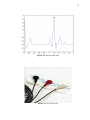
Step 1:
Make sure you have one unit of 3-leads selectable ECG electrodes,
MDIZ, MDIZB PC, internet connection, Bluetooth connection and
webcam
Step 2:
Install bsvidchatsdk free setup into your PC
Step 3:
Copy 2 folders named Tele-ECG Server and Tele-ECG Client(for
medical expert) while Tele-ECG Client2 (for client such as patient)
Step 4:
Fix the ECG electrodes to your body (for client)
Step 5:
Turn on MDIZ and MDIZB
Step 6:
Once the Bluetooth is connected, you can open the .exe file (VidSrv.exe
in the folder Tele-ECG Server while VidCln.exe in the folders TeleECG Client and Tele-ECG Client2)
35
Step 7:
Check IP address
Step 8:
Enter correct IP address and Port number
Step 9:
Enter username and password (optionally but recommended)
Step 10:
Connect to the Tele-ECG Server GUI
Step 11:
Connect to the Tele-ECG Client GUI
Step 12:
Once both parties are connected, ECG waveform will display and heart
rate will calculated automatically
Step 13:
Click Send Alert button to send alert message
Step 14:
Click Start Chat button to chat
Step 15:
Click Begin Talk to request a call
Step 16:
Click End Talk to end a call
Step 17:
There are other options that you can try such as play and record audio
and video, voice activation and compression, video frame rate and
compression
Step 18:
Click Disconnect button to disconnect to the server
Step 19:
Click Exist button to exist the program
CHAPTER 4
RESULTS AND ANALYSIS
This chapter described the hardware and software testing, result and further
analysis for the GUI design. Three BPM values are tested in this experiment to
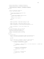
determine the relationship between heart rate and the ECG waveform.
4.1
Tele-ECG Server GUI Testing
Let says Thomas is doctor while Jacky is patient. First, Thomas opens TeleECG Server GUI to create a private secure server as shown in Figure 4.1.
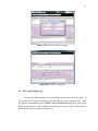
Figure 4.1: Tele-ECG Server
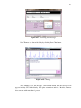
Then, IP address is checked by clicking My IP button. Example, Figure 4.2
shows that the IP address is 10.50.38.11.
37
Figure 4.2: Checking IP address
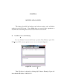
Then, click the Users button to add users.
Figure 4.3: Add Users
For example, key in username as his patient’s name Jacky, password as 1234
then click OK button.
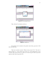
Then key in another username, Thomas and password 1122. The result is
shown in Figure 4.5. After add the users in this step, it will automatically save the
username and password of the users. Thus user no need to type his name or password
again next time when he open this GUI.
38
Figure 4.4: Enter username and password
Figure 4.5: Adding 2 Users
Optionally, user can adjust the setting of the GUI. For instance, no encryption,
symmetric encryption or asymmetric encryption.
39
Figure 4.6: No encryption
Figure 4.7: Symmetric encryption
After that, open Tele-ECG Client to connect to the private server by entering
the correct IP address, Port number, username and password. Otherwise, failure of
connecting to server message will pop up.
40
Figure 4.8: Asymmetric encryption
Figure 4.9: Connect to Server (medical expert)
4.2
Tele-ECG Client GUI Testing
When both of them are successfully connected to the server that created by
Thomas, then Thomas can view his patient’s name, Jacky appear in the Peers region
with name, time and status stated as Connected in his Tele-ECG Client GUI.
While Jacky also can note that Thomas is connected in his GUI.
41
Figure 4.10: Connect to Server (client)
Figure 4.11: Jacky is connected
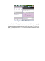
4.3
ECG Signal Displaying
Let says the ECG simulator acts as the ECG device places on Jacky’s body. It
will produce ECG signal according to the input that we adjust on that device. Then
the signal is transmitted directly to MDIZ, then to MDIZB through Zigbee connection,
finally to Thomas’s PC. Thus, Thomas can observe his patient, Jacky’s ECG signal in
real time in his GUI as shown in Figure 4.13.
42
Figure 4.12: Thomas is connected
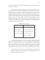
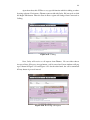
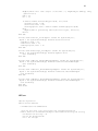
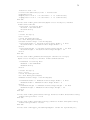
From figure 4.13, noticed that the heart rate is equal to 30 bpm. From the graph,
it is obviously show that the ECG waveform is very weak and low frequency. Thus this
is an abnormal ECG waveform, named sinus bradycardia because R-R interval more
than 1. It means that Jacky now is in a very dangerous situation and emergency action
is needed immediately.
43
Figure 4.13: ECG signal display (sinus bradycardia
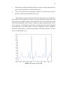
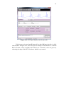
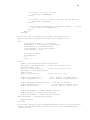
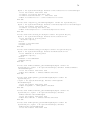
If the heart rate is more than 60 bpm and less than 100 bpm, then this is called
sinus rhythm. In Figure 4.14, heart rate equal to 66 bpm, means that this is a normal
ECG waveform. Jacky is healthy and his heart rate is normal. It also can prove by
observing the shape of the ECG waveform, which is very normal.
44
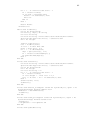
Figure 4.14: ECG signal display (sinus rhythm
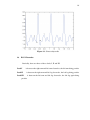
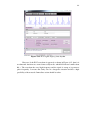
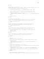
However, if the ECG waveform is appeared as shown in Figure 4.15, then it is
an abnormal situation too, named sinus tachycardia, which R-R interval smaller than
0.6 s. The waveform has very high frequency and the signal is strong as it generates
pulse frequently. It means that Jacky also in a dangerous situation and has a high
possibility of heart attack. Immediate action should be taken.
45
Figure 4.15: ECG signal display (sinus tachycardia
4.4
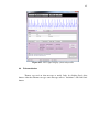
Teleconsultation
Thomas can send an alert message to notify Jacky by clicking Send Alert
button. After that Thomas can type some message such as ”Attention!” and click Send
button.
46
Figure 4.16: Sending alert message
Then Jacky will receive the alert message ”Attention!” that sent by Thomas in
his GUI.
47
Figure 4.17: Receiving alert message
Next Thomas can chat with Jacky by clicking Start Chat button.
Figure 4.18: Chatting
After Thomas types the message, click SEND button then the message will
appear in Jacky GUI immediately. It is quite convenient and fast. Besides, Thomas
also can chat with more than 1 person.
48
Apart from that, this GUI has a very special function which is talking to others
by using webcam. For instance, Thomas wants to talk with Jacky. He just needs to click
the Begin Talk button. Then the State in Peers region will change from Connected to
Calling.
Figure 4.19: Calling
Next, Jacky will receive a call request from Thomas. He can either choose
Accept or Deny. If he press Accept button, a call is started and 2 new windows will pop
up as shown in Figure 4.21 and Figure 4.22. On the other hand, the call is terminated
if Deny button is pressed instead.
Figure 4.20: Receiving call request
49
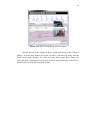
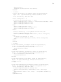
Figure 4.21: Video-conferencing (medical expert)
Noticed that the State column in Peers region will change from Calling to
Talking. It means that Thomas and Jacky can talk to each other by using webcam.
Local camera shows Thomas’s live video and audio while remote shows Jacky’s live
video and audio. During their conversation, the ECG signal still display in the GUI, so
Thomas still can make observation in all time.
50
Figure 4.22: Video-conferencing (client)
Figure 4.22 shows Jacky’s GUI which can also talk with Thomas by using
webcam. Now the local camera shows Jacky’s live video and audio while Remote
camera shows Thomas’s live video and audio. They can adjust some setting such as
voice activation, voice compression, video frame rate or video compression. At last,
the call can terminated if the End Talk is pressed by either side.
Figure 4.23: End call
51
4.5
Optimization
The approach of testing and optimization is to make the software more flexible,
user-friendly and easier to be use in any computers without installation of Microsoft
Visual Studio 2008 or other versions. Thus, the embedded program needs to convert
as standalone execution file (in .exe format).
CHAPTER 5
CONCLUSION AND RECOMMENDATION
5.1
Conclusion
As a conclusion here, ECG monitoring system and teleconsultation for medical
purpose is very important and required in telemedicine purposes. Thus a software
application (GUI) was successfully developed for wireless intensive ECG monitoring
system with the various useful functions such as ECG signal displaying in real time,
heart rate calculation automatically and teleconsultation purpose. Normal Heart rate
which is more than 60 bpm and less than 100 bpm. Heart rate which is out of this range
is consider abnormal.
5.2
Novelty
The system configuration and communication technology combination are
novel, which is the integration of Zigbee and Bluetooth. Besides that, integration
between ECG display GUI and video-conferencing is another novelty.
5.3
Limitation
There are some limitations in my project. First is alarm system. If the heart rate
is abnormal but at that time the doctor is busy and do not notice it, then the patient may
will in a very dangerous condition and any accident may happen. Thus alarm system
is needed. Next is PC problem. It is better the ECG signal can display in mobile phone
instead of PC because mobile phone is portable and more convenient. Furthermore,
this project only includes one vital sign signal that is ECG.
53
5.4
Recommendation
For further development of this project, it is recommended to add some more
vital sign signals such as detect SPO2, NIBP, temperature and respiration to make this
particular monitoring system more powerful, flexible and accurate. Besides that, 6leads or 12-leads selectable ECG can consider in this project instead of only using
3-leads selectable ECG to increase the accuracy of heart rate detection. Furthermore,
an alarm system should be implemented into the GUI so that it will alert the doctor if
an abnormality is found. Moreover, mobile phone can replace PC to display the ECG
signal in real time as it is lighter, smaller, portable and more convenient.
54
REFERENCES
1.
WHO. Atlas of Heart Disease and Stroke. September 2004.
2.
D. Bottazzi, A. C. and Montanari, R. Context-aware middleware solutions
for anytime and anywhere emergency assistance to elderly people. IEEE
Communications Magazine, 2006. 44(4): 82–90.
3.
Y. B. Choi, H. S. K. E. C., J. S. Krause and Chung, K. Telemedicine
in the USA: standardization through information management and technical
applications. IEEE Communications Magazine, 2006. 44(4): 41–48.
4.
Elizabeth Krupinski, R. P. D. E. R. S., Michelle Nypaver and Sapci, H. Clinical
Applications in Telemedicine/Telehealth. IEEE Communications Magazine,
2002. 8(1).
5.
P. Standing, A. C., M. Dent and Glenville, B. Changes in referral patterns
to cardiac out-patient clinics with ambulatory ECG monitoring in general
practice. The British Journal of Cardiology, 2001. 8(6): 396–398.
6.
Sanjay Sood, S. J. R. D. C. R. D. N. P. R. C. M., Victor Mbarika. What
is Telemedicine? A Collection of 104 Peer-Reviewed Perspectives and
Theoretical Underpinnings. Telemedicine and e-Health, 2007. 13(5): 573–
590.
7.
Meystre, S. The Current State of Telemonitoring: A Comment on the
Literature. Telemedicine and e-Health, 2005. 11(1).
8.
Consultation, W. G. Health Telematics Policy in support of the renewed
Health-for All Strategy in the 21st century. Geneva. 1997.
9.
Shimuzu, K. Telemedicine by Mobile Communication. IEEE Engineering in
Medicine and Biology, 1999.
10.
Tanriverdi, H. and Iacono, C. S. Diffusion of Telemedicine: A Knowledge
Barrier Perspective. Telemedicine Journal, 1999. 5(3).
11.
Jasemian, . N. L., Y. Design and Implementation of a Telemedicine System
Using Bluetooth Protocol and GSM/GPRS Network, for Real-Time Remote
Patient Monitoring. Technology and HealthCare 13, 2005. 13.
55
12.
L. Cromwell, E. P., F.J. Weibell. Design and Implementation of a Telemedicine
System Using Bluetooth Protocol and GSM/GPRS Network, for Real-Time
Remote Patient Monitoring. Technology and HealthCare, 2005. 13.
13.
C. Saritha, Y. N. M., V. Sukanya. ECG Signal Analysis Using Wavelet
Transforms. Bulg. J. Phys., 2008. 35: 68–77.
14.
C. Li, C. T., C. Zheng. IEEE Trans. Biomed. Eng. 42. 1995. 21–28.
15.
E. Supriyanto, I. M., H. Satria and Putra, E. A NOVEL LOW COST
TELEMEDICINE SYSTEM USING WIRELESS MESH NETWORK. Ph.D.
Thesis. Faculty of Biomedical Engineering and Health Science, Faculty of
Electrical Engineering, Universiti Teknologi Malaysia.
56
APPENDIX A
TELE-ECG SERVER
CFMain
Public Class CFMain
Public WithEvents VidSrv As bsVideoServerSDK.VideoServer
Dim FSettings As CFSettings
Dim FUsers As CFUsers
’Initializations
Private Sub CFoMain_Load(ByVal eventSender As System.Object, ByVal eventArgs
As System.EventArgs) Handles MyBase.Load
VidSrv = New bsVideoServerSDK.VideoServer
FSettings = New CFSettings
’create the settings form
FSettings.FMain = Me
SetSettings()
FUsers = New CFUsers
’create the users form
FUsers.LoadUsers()
btnStart.PerformClick() ’Start the server automatically
UpdateStatus()
End Sub
Private Function GetUsername(ByVal aHandle As Integer) As String
GetUsername = VidSrv.GetClientName(aHandle)
If GetUsername = "" Then
GetUsername = "Guest"
End If
End Function
’Update the status text
Private Sub UpdateStatus()
If VidSrv.Running Then
StatusBar.Panels.Item(0).Text = "Started"
btnStart.Enabled = False
btnStop.Enabled = True
Else
StatusBar.Panels.Item(0).Text = "Stopped"
btnStart.Enabled = True
btnStop.Enabled = False
End If
If lvClients.Items.Count = 0 Then
57
StatusBar.Panels.Item(1).Text = "No active connection"
Else
StatusBar.Panels.Item(1).Text = Str(lvClients.Items.Count)
+ " connection(s)"
End If
btnRemove.Enabled = lvClients.SelectedItems.Count > 0
End Sub
’Set the component properties
Private Sub SetSettings()
VidSrv.ListeningPort = Val(FSettings.txtPort.Text)
If FSettings.radSecret.Checked Then
VidSrv.SecurityMode = 1
Else
If FSettings.radPublic.Checked Then
VidSrv.SecurityMode = 2
Else
VidSrv.SecurityMode = 0
End If
End If
VidSrv.SecretKey = FSettings.txtSecret.Text
VidSrv.PublicKey = FSettings.txtPublic.Text
VidSrv.PrivateKey = FSettings.txtPrivate.Text
VidSrv.Fingerprints = FSettings.txtFingerprints.Text
End Sub
’Add a message to the log
Private Sub LogMsg(ByVal aText As String)
Dim Line As String
If txtLog.Text > "" Then
Line = Chr(13) & Chr(10)
Else
Line = ""
End If
Line = Line & "[" & Now.ToLongTimeString & "] : "
Line = Line & aText
txtLog.SelectionStart = Len(txtLog.Text)
txtLog.SelectedText = Line
End Sub
Private Function ItemFromHandle(ByVal aHandle As Long) As ListViewItem
’iterate on the list
Dim i As Integer
For i = 0 To lvClients.Items.Count - 1
If lvClients.Items(i).Tag = aHandle Then
ItemFromHandle = lvClients.Items(i)
Exit Function
End If
Next i
ItemFromHandle = Nothing
End Function
’Start the server
Private Sub btnStart_Click(ByVal sender As System.Object,
58
ByVal e As System.EventArgs)
Handles btnStart.Click
If VidSrv.Start Then
LogMsg(("Server is started"))
Else
Call MsgBox("Cannot start the server!", "Error")
End If
UpdateStatus()
End Sub
’Stop the server
Private Sub btnStop_Click(ByVal eventSender As System.Object, ByVal eventArgs
As System.EventArgs) Handles btnStop.Click
Dim i As Integer
VidSrv.Stop()
For i = lvClients.Items.Count - 1 To 0 Step -1
VidSrv.DisconnectClient(lvClients.Items(i).Tag)
Next i
UpdateStatus()
LogMsg("Server is stopped")
End Sub
’Modify the settings
Private Sub btnSettings_Click(ByVal eventSender As System.Object, ByVal
eventArgs
As System.EventArgs) Handles btnSettings.Click
If FSettings.ShowDialog <> DialogResult.OK Then Exit Sub
SetSettings()
UpdateStatus()
End Sub
’Show my IP address
Private Sub btnIP_Click(ByVal sender As System.Object, ByVal e As
System.EventArgs) Handles btnIP.Click
MsgBox(VidSrv.LocalIPList, , "My IP address")
End Sub
Private Sub btnExit_Click(ByVal sender As System.Object, ByVal e As
System.EventArgs) Handles btnExit.Click
End
End Sub
’Remove a client connection
Private Sub btnRemove_Click(ByVal eventSender As System.Object, ByVal
eventArgs As System.EventArgs) Handles btnRemove.Click
If lvClients.SelectedItems.Count = 0 Then Exit Sub
VidSrv.DisconnectClient(lvClients.SelectedItems(0).Tag)
UpdateStatus()
End Sub
’Clear the log
Private Sub btnClear_Click(ByVal sender As System.Object, ByVal e As
System.EventArgs) Handles btnClear.Click
txtLog.Text = ""
59
End Sub
’A list view item is clicked
Private Sub lvPeers_SelectedIndexChanged(ByVal sender As System.Object,
ByVal e As System.EventArgs) Handles lvClients.SelectedIndexChanged
UpdateStatus()
End Sub
’ *** VidSrv events ***
’A new peer is just connected
Private Sub VidSrv_OnClientConnected(ByVal aHandle As Integer) Handles
VidSrv.OnClientConnected
Dim LI As ListViewItem
LI = lvClients.Items.Add(GetUsername(aHandle))
LI.Tag = aHandle
LI.SubItems.Add(VidSrv.GetClientAddress(aHandle))
LI.SubItems.Add(Str(VidSrv.GetClientPort(aHandle)))
LI.SubItems.Add(Now.ToLongTimeString)
LI.SubItems.Add("Connected")
UpdateStatus()
LogMsg(("New connection from " + LI.SubItems(1).Text + ":"
+ LI.SubItems(2).Text))
End Sub
’A connection is broken
Private Sub VidSrv_OnClientDisconnected(ByVal aHandle As Integer, ByVal aCode
As Integer) Handles VidSrv.OnClientDisconnected
Dim LI As ListViewItem
LI = ItemFromHandle(aHandle)
If LI Is Nothing Then Exit Sub
LogMsg("Disconnected " & LI.Text & " " + Str(aCode))
lvClients.Items.Remove(LI)
End Sub
’A connection is refused
Private Sub VidSrv_OnClientRejected(ByVal aUsername As String, ByVal aAddress
As String, ByVal aPort As Integer, ByVal aCode As Integer) Handles
VidSrv.OnClientRejected
LogMsg("Rejected client " + aUsername + " " + aAddress + ":" + Str(aPort))
End Sub
’A request from a new peer
Private Sub VidSrv_OnConnectionRequest(ByVal aHandle As Integer, ByVal
aUsername As String, ByRef aPassword As String, ByRef aAccept As Boolean)
Handles VidSrv.OnConnectionRequest
aAccept = True
If aUsername <> "" Then
’not a Guest user, look for the password
aPassword = FUsers.FindPassword(aUsername)
End If
End Sub
’Access control
Private Sub btnUsers_Click(ByVal sender As System.Object, ByVal e As
System.EventArgs) Handles btnUsers.Click
FUsers.ShowDialog()
End Sub
60
End Class
CFEditUser
Public Class CFEditUser
Public Function EditUser(ByVal aUsername As String, ByVal aPassword As
String) As Boolean
txtUsername.Text = aUsername
txtPassword.Text = aPassword
Return (ShowDialog() = DialogResult.OK)
End Function
Private Sub btnOk_Click(ByVal sender As System.Object, ByVal e As
System.EventArgs) Handles btnOk.Click
If (Trim(txtUsername.Text) = "") Or (Trim(txtPassword.Text) = "") Then
MsgBox("There are empty fields!")
Exit Sub
End If
DialogResult = DialogResult.OK
End Sub
Private Sub CFEditUser_Load(ByVal sender As System.Object, ByVal
e As System.EventArgs) Handles MyBase.Load
End Sub
End Class
CFSettings
Public Class CFSettings
Public FMain As CFMain
Private Sub SetMode()
frmSecret.Enabled = radSecret.Checked
txtSecret.Enabled = radSecret.Checked
frmKeypair.Enabled = radPublic.Checked
lblPublic.Enabled = radPublic.Checked
lblPrivate.Enabled = radPublic.Checked
lblFingerprint.Enabled = radPublic.Checked
btnGenerate.Enabled = radPublic.Checked
btnClear.Enabled = radPublic.Checked
frmFingerprints.Enabled = radPublic.Checked
txtFingerprints.Enabled = radPublic.Checked
End Sub
Private Sub
ByVal e As
Dim Pub
Dim Pri
btnGenerate_Click(ByVal sender As System.Object,
System.EventArgs) Handles btnGenerate.Click
As String
As String
61
MsgBox("This will take couple of seconds...", MsgBoxStyle.OkOnly, "Key
generation!")
Pub = ""
Pri = ""
If FMain.VidSrv.GenerateKeypair(Pub, Pri) Then
txtPublic.Text = Pub
txtPrivate.Text = Pri
txtFingerprint.Text = FMain.VidSrv.TakeFingerprint(Pub)
Else
MsgBox("Error generating Public/Private keys", "Error!")
End If
End Sub
Private Sub btnClear_Click(ByVal sender As System.Object,
ByVal e As System.EventArgs) Handles btnClear.Click
txtPublic.Text = ""
txtPrivate.Text = ""
txtFingerprint.Text = ""
End Sub
Private Sub CFSettings_Load(ByVal sender As System.Object,
ByVal e As System.EventArgs) Handles MyBase.Load
Call SetMode()
End Sub
Private Sub radPlain_CheckedChanged(ByVal sender As System.Object,
ByVal e As System.EventArgs) Handles radPlain.CheckedChanged
Call SetMode()
End Sub
Private Sub radSecret_CheckedChanged(ByVal sender As System.Object,
ByVal e As System.EventArgs) Handles radSecret.CheckedChanged
Call SetMode()
End Sub
Private Sub radPublic_CheckedChanged(ByVal sender As System.Object,
ByVal e As System.EventArgs) Handles radPublic.CheckedChanged
Call SetMode()
End Sub
End Class
CFUsers
Imports System.IO
Public Class CFUsers
Dim FEditUser As CFEditUser
’Look up the user list and return the assigned password
Public Function FindPassword(ByVal aUsername As String) As String
Dim Result As String = ""
Dim LI As ListViewItem
Dim i As Integer
62
For i = 0 To lvUsers.Items.Count - 1
LI = lvUsers.Items(i)
If LI.Text = aUsername Then
Result = LI.SubItems(1).Text
Exit For
End If
Next i
Return Result
End Function
Public Sub LoadUsers()
Dim LI As ListViewItem
Dim Users(), Napa() As String
Dim Data As String
Dim Path As String = Environment.GetFolderPath(Environment.
SpecialFolder.ApplicationData) + "\bsusers.dat"
Dim i As Integer
lvUsers.Items.Clear()
Data = LoadFile(Path)
If Data = "" Then Exit Sub
Users = Split(Data, ",")
For i = 0 To UBound(Users)
Napa = Split(Users(i), "=")
LI = lvUsers.Items.Add(Napa(0))
LI.SubItems.Add(Napa(1))
Next i
End Sub
Private Sub SaveUsers()
Dim Path As String = Environment.GetFolderPath(Environment.
SpecialFolder.ApplicationData) + "\bsusers.dat"
Dim LI As ListViewItem
Dim i As Integer
Dim Data As String = ""
For i = 0 To lvUsers.Items.Count - 1
LI = lvUsers.Items(i)
If Data.Length > 0 Then Data += ","
Data += LI.Text + "=" + LI.SubItems(1).Text
Next i
SaveFile(Path, Data)
LoadUsers()
End Sub
Private Sub CFUsers_Load(ByVal sender As System.Object, ByVal e As
System.EventArgs) Handles MyBase.Load
FEditUser = New CFEditUser()
LoadUsers()
End Sub
Private Sub btnOk_Click(ByVal sender As System.Object, ByVal e As
System.EventArgs) Handles btnOk.Click
SaveUsers()
DialogResult = DialogResult.OK
End Sub
Private Sub UpdateButtons()
63
btnEdit.Enabled = lvUsers.SelectedItems.Count > 0
btnRemove.Enabled = lvUsers.SelectedItems.Count > 0
End Sub
Private Sub lvUsers_SelectedIndexChanged(ByVal sender As System.Object,
ByVal e As System.EventArgs) Handles lvUsers.SelectedIndexChanged
UpdateButtons()
End Sub
Private Sub CFUsers_Shown(ByVal sender As System.Object, ByVal e As
System.EventArgs) Handles MyBase.Shown
UpdateButtons()
End Sub
Private Sub btnAdd_Click(ByVal sender As System.Object, ByVal e As
System.EventArgs) Handles btnAdd.Click
Dim LI As ListViewItem
If Not FEditUser.EditUser("", "") Then Exit Sub
LI = lvUsers.Items.Add(FEditUser.txtUsername.Text)
LI.SubItems.Add(FEditUser.txtPassword.Text)
End Sub
Private Sub btnEdit_Click(ByVal sender As System.Object, ByVal e As
System.EventArgs) Handles btnEdit.Click
Dim LI As ListViewItem
LI = lvUsers.SelectedItems(0)
If Not FEditUser.EditUser(LI.Text, LI.SubItems(1).Text) Then Exit Sub
LI.Text = FEditUser.txtUsername.Text
LI.SubItems(1).Text = FEditUser.txtPassword.Text
End Sub
Private Sub btnRemove_Click(ByVal sender As System.Object, ByVal e As
System.EventArgs) Handles btnRemove.Click
lvUsers.Items.Remove(lvUsers.SelectedItems(0))
End Sub
End Class
64
APPENDIX B
TELE-ECG CLIENT
CFMain
Imports System.IO
Public Class CFMain
Public WithEvents VidCln As bsVideoClientSDK.VideoClient
Public Peers As New Collection
Friend ThePeer, SelPeer As CClient
’ECG declaration
Dim grafik As System.Drawing.Graphics
Dim pensil As New System.Drawing.Pen(System.Drawing.Color.DarkRed)
Dim gMyGraphics As Graphics
Dim pMyPen As Pen
Dim cLatar As SolidBrush = New SolidBrush(Color.White)
Dim PictureWidth, PictureHeight As ULong
Dim y(5) As Single
Dim xStep, x, xAwal As Single
Dim incoming As Byte
Dim graphed As Byte
Dim NextStatus As Byte
Dim oldgraphed As Byte
Const HEARTRATE As Byte = 2
Const NOTDATA As Byte = 1
Const ISDATA As Byte = 0
’client declaration
Dim FSettings As CFSettings
Dim FConnect As CFConnect
Dim FAlert As CFAlert
Dim FAcceptCall As CFAcceptCall
Dim FLocCam As CFLocCam
Dim FRemCam As CFRemCam
Const SESSION_STATE_CONNECTING = 1
Const SESSION_STATE_CONNECTED = 2
’Add a message to the log
Private Sub LogMsg(ByVal aText As String)
Dim Line As String
If txtLog.Text > "" Then
65
Line = Chr(13) & Chr(10)
Else
Line = ""
End If
Line = Line & "[" & Now.ToLongTimeString & "] : "
Line = Line & aText
txtLog.SelectionStart = Len(txtLog.Text)
txtLog.SelectedText = Line
End Sub
Friend Function drawTemplate() As Integer
Dim height As UInt16
cLatar.Color = Color.White
gMyGraphics.FillRectangle(cLatar, 0, 0, PictureBox1.Width, PictureBox1
.Height)
height = PictureHeight / 2
pMyPen = New Pen(Color.Red, 1.5)
gMyGraphics.DrawLine(pMyPen, 0, height, PictureBox1.Width, height)
End Function
Friend Function drawGraph(ByVal graphed) As Integer
pMyPen = New Pen(Color.White, 1)
Dim i As Single
For i = 0 To xStep
gMyGraphics.DrawLine(pMyPen, x, i, x, PictureBox1.Height)
gMyGraphics.DrawLine(pMyPen, x + i, i, x + i, PictureBox1.Height)
Next i
pMyPen = New Pen(Color.Blue, 1)
gMyGraphics.DrawLine(pMyPen, x - xStep, 256 - oldgraphed, x, 256
- graphed)
x = x + xStep
oldgraphed = graphed
If x > 625 Then
x = 0
End If
End Function
Friend Function PeerFromHandle(ByVal aHandle As Long) As CClient
Dim Pr As CClient
PeerFromHandle = Nothing
For Each Pr In Peers
’ Iterate through elements.
If Pr.Handle = aHandle Then
PeerFromHandle = Pr
Exit For
’ Exit loop.
End If
Next
End Function
Public Function PickPeer(ByVal aHandle As Long) As Boolean
ThePeer = PeerFromHandle(aHandle)
PickPeer = Not (ThePeer Is Nothing)
End Function
Public Function SelectPeer() As Boolean
66
SelectPeer = False
If lvPeers.SelectedItems.Count = 0 Then Exit Function
SelPeer = lvPeers.SelectedItems(0).Tag
SelectPeer = Not (SelPeer Is Nothing)
End Function
’Update the button state and the status text
Private Sub UpdateStatus()
If VidCln.GetSessionState = SESSION_STATE_CONNECTED Then
’already connected
btnConnect.Enabled = False
btnCancel.Enabled = False
btnDisconnect.Enabled = True
StatusBar.Panels(0).Text = " Session open"
StatusBar.Panels(1).Text = " Server: " + VidCln.ServerAddress + ":"
+ Str(VidCln.ServerPort)
If VidCln.Username > "" Then
StatusBar.Panels(2).Text = " User: " + VidCln.Username
Else
StatusBar.Panels(2).Text = " User: not signed in"
End If
Else
StatusBar.Panels(1).Text = ""
StatusBar.Panels(2).Text = ""
If VidCln.GetSessionState = SESSION_STATE_CONNECTING Then
’now connecting
btnConnect.Enabled = False
btnCancel.Enabled = True
btnDisconnect.Enabled = False
StatusBar.Panels(0).Text = " Connecting to the hub"
Else
’not connected
btnConnect.Enabled = True
btnCancel.Enabled = False
btnDisconnect.Enabled = False
StatusBar.Panels(0).Text = " Session closed"
End If
End If
UpdateButtons()
End Sub
Private Sub UpdateButtons()
btnAlert.Enabled = lvPeers.SelectedItems.Count > 0
btnChat.Enabled = lvPeers.SelectedItems.Count > 0
btnRemove.Enabled = lvPeers.SelectedItems.Count > 0
btnBeginTalk.Enabled = False
If lvPeers.SelectedItems.Count > 0 Then
If (VidCln.GetCaller = 0) And (VidCln.GetTalkerCount = 0) Then
btnBeginTalk.Enabled = True
End If
End If
btnEndTallk.Enabled = VidCln.GetTalkerCount > 0
chkRecordAudio.Enabled = btnEndTallk.Enabled
chkPlayAudio.Enabled = btnEndTallk.Enabled
67
btnLocalCam.Enabled = btnEndTallk.Enabled
btnRemoteCam.Enabled = btnEndTallk.Enabled
trkVoiceActivation.Enabled = btnEndTallk.Enabled
trkVideoCompression.Enabled = btnEndTallk.Enabled
End Sub
’Set the component properties
Private Sub SetSettings()
If FSettings.radSecret.Checked Then
VidCln.SecurityMode = 1
Else
If FSettings.radPublic.Checked Then
VidCln.SecurityMode = 2
Else
VidCln.SecurityMode = 0
End If
End If
VidCln.SecretKey = FSettings.txtSecret.Text
VidCln.PublicKey = FSettings.txtPublic.Text
VidCln.PrivateKey = FSettings.txtPrivate.Text
VidCln.Fingerprints = FSettings.txtFingerprints.Text
VidCln.BindAddress = FSettings.txtAddr.Text
End Sub
Sub DeletePeer(ByVal aPeer As CClient)
If aPeer Is Nothing Then Exit Sub
Peers.Remove(Str(aPeer.Handle))
VidCln.DisconnectPeer(aPeer.Handle)
lvPeers.Items.Remove(aPeer.ListItem)
End Sub
’Initializations
Private Sub Button1_Click(ByVal sender As System.Object,
ByVal e As System.EventArgs) Handles Button1.Click
x = 0
End Sub
Private Sub Timer1_Tick(ByVal sender As System.Object,
ByVal e As System.EventArgs) Handles Timer1.Tick
If SerialPort1.BytesToRead > 0 Then
incoming = SerialPort1.ReadByte
If incoming <> 0 And incoming <= 246 And NextStatus = ISDATA Then
drawGraph(incoming)
End If
If NextStatus = HEARTRATE Then
TextBox1.Text = incoming
NextStatus = ISDATA
End If
If NextStatus = NOTDATA Then
NextStatus = ISDATA
End If
68
If incoming = 250 Then ’FA then
NextStatus = HEARTRATE
End If
If incoming = 249 Or incoming = 251 Then ’F9 dan FB then
NextStatus = NOTDATA
End If
If SerialPort1.BytesToRead > (PictureBox1.Width * 1.5) Then
SerialPort1.DiscardInBuffer()
End If
End If
End Sub
Private Sub fMain_Load(ByVal eventSender As System.Object,
ByVal eventArgs As System.EventArgs) Handles MyBase.Load
’ECG
PictureBox1.BackColor = Color.White
gMyGraphics = PictureBox1.CreateGraphics
PictureWidth = PictureBox1.Width
PictureHeight = PictureBox1.Height
Timer1.Enabled = True
SerialPort1.Open()
drawTemplate()
x = 0
xStep = 1
’client
VidCln = New bsVideoClientSDK.VideoClient
FSettings = New CFSettings
’create the settings form
FSettings.FMain = Me
FConnect = New CFConnect
’create the connection form
FAcceptCall = New CFAcceptCall
SetSettings()
FAlert = New CFAlert
’create the alert form
VidCln.RecordingDevice = 0
VidCln.PlaybackDevice = 0
’select default recording device
’select default playback device
VidCln.FindCaptureCapabilities()
VidCln.CaptureDevice = 0
VidCln.CaptureFormat = 0
’find capture devices
’select default capture device
’select default capture size
VidCln.RecordAudio = chkRecordAudio.Checked
VidCln.PlayAudio = chkPlayAudio.Checked
VidCln.RecordVideo = chkRecordVideo.Checked
VidCln.PlayVideo = chkPlayVideo.Checked
UpdateStatus()
End Sub
Private Sub lvPeers_SelectedIndexChanged(ByVal sender As System.Object,
ByVal e As System.EventArgs) Handles lvPeers.SelectedIndexChanged
UpdateStatus()
69
End Sub
’Connecting to the server
Private Sub btnConnect_Click(ByVal sender As System.Object, ByVal e As
System.EventArgs) Handles btnConnect.Click
If FConnect.ShowDialog <> DialogResult.OK Then Exit Sub
If Not VidCln.OpenSession(FConnect.txtSrvAddr.Text, Val
(FConnect.txtSrvPort
.Text), FConnect.txtUsername.Text,
FConnect.txtPassword.Text) Then
MsgBox("Cannot initiate a new session: " + Str(VidCln.LastError))
End If
UpdateStatus()
End Sub
’Disconnect from the server
Private Sub btnDisconnect_Click(ByVal sender As System.Object,
ByVal e As System.EventArgs) Handles btnDisconnect.Click
VidCln.CloseSession()
End Sub
Private Sub btnCancel_Click(ByVal sender As System.Object,
ByVal e As System.EventArgs) Handles btnCancel.Click
VidCln.CloseSession()
End Sub
Private Sub btnSettings_Click(ByVal sender As System.Object,
ByVal e As System.EventArgs) Handles btnSettings.Click
If FSettings.ShowDialog <> DialogResult.OK Then Exit Sub
SetSettings()
UpdateStatus()
End Sub
Private Sub btnExit_Click(ByVal sender As System.Object,
ByVal e As System.EventArgs) Handles btnExit.Click
Close()
End Sub
’ Events
’Just connected to the server
Private Sub VidCln_OnSessionOpen() Handles VidCln.OnSessionOpen
UpdateStatus()
LogMsg("Connected to the server " + VidCln.ServerAddress + ":"
+ Str(VidCln.ServerPort))
End Sub
’Unsuccessful connection to the server
Private Sub VidCln_OnSessionRejected(ByVal aCode As Integer) Handles
VidCln.OnSessionRejected
LogMsg("Cannot open a session to" + FConnect.txtSrvAddr.Text + ":"
+ FConnect.txtSrvPort.Text + "
Error- " + ErrorText(aCode))
MsgBox("Cannot open the session! Error: " + ErrorText(aCode))
UpdateStatus()
End Sub
’Just disconnected from the server
Private Sub VidCln_OnSessionClosed() Handles VidCln.OnSessionClosed
70
UpdateStatus()
LogMsg("Disconnected from the server")
End Sub
’ *** Alert
Private Sub btnAlert_Click(ByVal sender As System.Object,
ByVal e As
System.EventArgs) Handles btnAlert.Click
If Not SelectPeer() Then Exit Sub
FAlert.txtMsg.Text = ""
If lvPeers.SelectedItems.Count > 0 Then
FAlert.radSingle.Text = "User " + lvPeers.SelectedItems(0).Text
FAlert.radSingle.Enabled = True
FAlert.radSingle.Checked = True
Else
FAlert.radAll.Checked = True
FAlert.radSingle.Text = "Single user"
FAlert.radSingle.Enabled = False
End If
If FAlert.ShowDialog <> DialogResult.OK Then Exit Sub
If FAlert.radSingle.Checked Then
VidCln.SendAlertMessage(SelPeer.Handle, FAlert.txtMsg.Text)
Else
For Each Pr As CClient In Peers
VidCln.SendAlertMessage(Pr.Handle, FAlert.txtMsg.Text)
Next
End If
End Sub
’ *** Chat
Private Sub btnChat_Click(ByVal sender As System.Object,
ByVal e As System.EventArgs) Handles btnChat.Click
If Not SelectPeer() Then Exit Sub
ShowForm(SelPeer.FChat)
End Sub
Private Sub btnRemove_Click(ByVal sender As System.Object,
ByVal e As System.EventArgs) Handles btnRemove.Click
If Not SelectPeer() Then Exit Sub
DeletePeer(SelPeer)
End Sub
Private Sub btnClear_Click(ByVal sender As System.Object,
ByVal e As System.EventArgs) Handles btnClear.Click
txtLog.Clear()
End Sub
Private Sub btnBeginTalk_Click(ByVal sender As System.Object,
ByVal e As System.EventArgs) Handles btnBeginTalk.Click
If Not SelectPeer() Then Exit Sub
If VidCln.BeginTalk(SelPeer.Handle) Then
lvPeers.SelectedItems(0).SubItems(2).Text = "Calling"
Else
MsgBox("Cannot make a call, code: " + Str(VidCln.LastError))
End If
UpdateButtons()
71
End Sub
Private Sub btnEndTalk_Click(ByVal sender As System.Object, ByVal e As
System.EventArgs) Handles btnEndTallk.Click
VidCln.EndTalk() ’end the conversation
lblCaller.Text = ""
Dim i As Long
For i = 0 To lvPeers.Items.Count - 1
lvPeers.Items.Item(0).SubItems(2).Text = "Connected"
Next i
UpdateButtons()
End Sub
’A new peer is just created
Private Sub VoiCln_OnPeerConnected(ByVal aHandle As Integer) Handles
VidCln.OnPeerConnected
Dim Pr As New CClient
Dim LI As ListViewItem
Pr.Handle = aHandle
Peers.Add(Pr, Str(Pr.Handle))
Pr.Username = NiceName(VidCln.GetPeerName(Pr.Handle))
’create the chat form
Pr.FChat = New CFChat
Pr.FChat.FMain = Me
Pr.FChat.Peer = Pr
Pr.FChat.Text = "Chat with " + Pr.Username
LI = lvPeers.Items.Add(Pr.Username)
Pr.ListItem = LI
LI.Tag = Pr
LI.SubItems.Add(Now.ToLongTimeString)
LI.SubItems.Add("Connected")
If lvPeers.SelectedItems.Count = 0 Then
LI.Selected = True
End If
UpdateStatus()
LogMsg("New peer at " + LI.Text + ":" + LI.SubItems(1).Text)
End Sub
’A peer is just disconnected
Private Sub VidCln_OnPeerDisconnected(ByVal aHandle As Integer) Handles
VidCln.OnPeerDisconnected
Dim Pr As CClient
Pr = PeerFromHandle(aHandle)
If Pr Is Nothing Then Exit Sub
LogMsg("Disconnected peer " + Pr.ListItem.Text + " " + Pr.ListItem
.SubItems(1).Text + ":" + Pr.ListItem.SubItems(2).Text)
DeletePeer(Pr)
End Sub
’An alert message is available
72
Private Sub VidCln_OnAlertMessage(ByVal aHandle As Integer,
ByVal aText As String) Handles VidCln.OnAlertMessage
’An alert message is available
If Not PickPeer(aHandle) Then Exit Sub
MsgBox(aText, , "Alert from " + ThePeer.Username)
End Sub
’A chat message is available
Private Sub VidCln_OnChatMessage(ByVal aHandle As Integer, ByVal
aText As String) Handles VidCln.OnChatMessage
If Not PickPeer(aHandle) Then Exit Sub
ThePeer.FChat.HaveChatMessage(aText)
End Sub
Private Sub VidCln_OnTalkInvited(ByVal aHandle As Integer, ByRef
aOkay As Boolean) Handles VidCln.OnTalkInvited
Dim Pr As CClient
Pr = PeerFromHandle(aHandle)
If Pr Is Nothing Then Exit Sub
LogMsg("Call is requested from " + Pr.Username + " " + Pr.ListItem
.SubItems(1)
.Text + ":" + Pr.ListItem.SubItems(2).Text)
FAcceptCall.Text = "Call is requested from " + Pr.Username
If FAcceptCall.ShowDialog = DialogResult.OK Then
aOkay = True
End If
End Sub
Private Sub VidCln_OnTalkBegan(ByVal aHandle As Integer) Handles
VidCln.OnTalkBegan
Dim Pr As CClient
Pr = PeerFromHandle(aHandle)
If Pr Is Nothing Then Exit Sub
Pr.ListItem.SubItems(2).Text = "Talking"
lblCaller.Text = Pr.ListItem.Text
VidCln.VoiceActivation = trkVoiceActivation.Value
FLocCam = Nothing
FRemCam = Nothing
UpdateButtons()
LogMsg("Call from " + Pr.Username + " is taken")
End Sub
Private Sub VidCln_OnTalkRefused(ByVal aHandle As Integer,
ByVal aCode As Integer) Handles VidCln.OnTalkRefused
Dim Pr As CClient
Pr = PeerFromHandle(aHandle)
If Pr Is Nothing Then Exit Sub
Pr.ListItem.SubItems(2).Text = "Connected"
UpdateButtons()
MsgBox("Call from " + Pr.Username + " is rejected")
LogMsg("Call from " + Pr.Username + " is rejected")
End Sub
Private Sub VidCln_OnTalkEnded(ByVal aHandle As Integer) Handles
VidCln.OnTalkEnded
Dim Pr As CClient
Pr = PeerFromHandle(aHandle)
If Pr Is Nothing Then Exit Sub
73
lblCaller.Text = ""
Pr.ListItem.SubItems(2).Text = "Connected"
UpdateButtons()
MsgBox("Call from " + Pr.Username + " is terminated")
LogMsg("Call from " + Pr.Username + " is terminated")
End Sub
Private Sub VidCln_OnLocalFrame(ByRef aData As Object) Handles
VidCln.OnLocalFrame
If FLocCam Is Nothing Then
FLocCam = New CFLocCam
FLocCam.Show()
End If
Dim buf As Byte()
buf = aData
Dim ms As MemoryStream
ms = New MemoryStream(buf)
FLocCam.PicBox.Image = New Bitmap(ms)
If FLocCam.Width <> FLocCam.PicBox.Image.Width + 8 Then
FLocCam.Width = FLocCam.PicBox.Image.Width + 8
End If
If FLocCam.Height <> FLocCam.PicBox.Image.Height + 24 Then
FLocCam.Height = FLocCam.PicBox.Image.Height + 24
End If
End Sub
Private Sub VidCln_OnRemoteFrame(ByVal aHandle As Integer,
ByRef aData As Object) Handles VidCln.OnRemoteFrame
If FRemCam Is Nothing Then
FRemCam = New CFRemCam
FRemCam.Show()
End If
Dim buf As Byte()
buf = aData
Dim ms As MemoryStream
ms = New MemoryStream(buf)
FRemCam.PicBox.Image = New Bitmap(ms)
If FRemCam.Width <> FRemCam.PicBox.Image.Width + 8 Then
FRemCam.Width = FRemCam.PicBox.Image.Width + 8
End If
If FRemCam.Height <> FRemCam.PicBox.Image.Height + 24 Then
FRemCam.Height = FRemCam.PicBox.Image.Height + 24
End If
End Sub
Private Sub VidCln_OnStartRecording() Handles VidCln.OnStartRecording
lblRecording.Visible = True
End Sub
Private Sub VidCln_OnStopRecording() Handles VidCln.OnStopRecording
lblRecording.Visible = False
End Sub
Private Sub trkTrigger_ValueChanged(ByVal sender As System.Object,
74
ByVal e As System.EventArgs) Handles trkVoiceActivation.ValueChanged
If Not Me.Visible Then Exit Sub
If VidCln Is Nothing Then Exit Sub
If VidCln.GetTalkerCount = 0 Then Exit Sub
VidCln.VoiceActivation = trkVoiceActivation.Value
End Sub
Private Sub trkQuality_ValueChanged(ByVal sender As System.Object,
ByVal e As System.EventArgs) Handles trkVideoCompression.ValueChanged
If Not Me.Visible Then Exit Sub
If VidCln Is Nothing Then Exit Sub
VidCln.VideoCompression = trkVideoCompression.Value
End Sub
Private Sub btnLocalCam_Click(ByVal sender As System.Object,
ByVal e As System.EventArgs) Handles btnLocalCam.Click
If Not FLocCam Is Nothing Then
FLocCam.Dispose()
End If
FLocCam = New CFLocCam
FLocCam.Show()
End Sub
Private Sub btnRemoteCam_Click(ByVal sender As System.Object,
ByVal e As System.EventArgs) Handles btnRemoteCam.Click
If Not FRemCam Is Nothing Then
FRemCam.Dispose()
End If
FRemCam = New CFRemCam
FRemCam.Show()
End Sub
Private Sub chkRecordAudio_CheckedChanged(ByVal sender As
System.Object, ByVal e As System.EventArgs) Handles chkRecordAudio
.CheckedChanged
If Not Me.Visible Then Exit Sub
VidCln.RecordAudio = chkRecordAudio.Checked
End Sub
Private Sub chkPlayAudio_CheckedChanged(ByVal sender As
System.Object,
\ ByVal e As System.EventArgs) Handles chkPlayAudio
.CheckedChanged
If Not Me.Visible Then Exit Sub
VidCln.PlayAudio = chkPlayAudio.Checked
End Sub
Private Sub chkRecordVideo_CheckedChanged(ByVal sender As
System.Object, ByVal e As System.EventArgs) Handles
chkRecordVideo.CheckedChanged
If Not Me.Visible Then Exit Sub
VidCln.RecordVideo = chkRecordVideo.Checked
End Sub
Private Sub chkPlayVideo_CheckedChanged(ByVal sender As
System.Object, ByVal e As System.EventArgs) Handles
chkPlayVideo.CheckedChanged
If Not Me.Visible Then Exit Sub
75
VidCln.PlayVideo = chkPlayVideo.Checked
End Sub
Private Sub trkVoiceActivation_Scroll(ByVal sender As
System.Object, ByVal e As System.EventArgs) Handles
trkVoiceActivation.Scroll
VidCln.VoiceActivation = trkVoiceActivation.Value
End Sub
Private Sub trkVoiceCompression_Scroll(ByVal sender As
System.Object, ByVal e As System.EventArgs) Handles
trkVoiceCompression.Scroll
VidCln.VoiceCompression = trkVoiceCompression.Value
End Sub
Private Sub trkFrameRate_Scroll(ByVal sender As
System.Object, ByVal e As System.EventArgs) Handles
trkFrameRate.Scroll
VidCln.FrameRate = trkFrameRate.Value
End Sub
Private Sub trkVideoCompression_Scroll(ByVal sender As
System.Object, ByVal e As System.EventArgs) Handles
trkVideoCompression.Scroll
VidCln.VideoCompression = trkVideoCompression.Value
End Sub
Private Sub CFMain_FormClosing(ByVal sender As System.Object,
ByVal e As System.Windows.Forms.FormClosingEventArgs) Handles
MyBase.FormClosing
VidCln.EndTalk()
End Sub
End Class
CFSettings
Public Class CFSettings
Public FMain As CFMain
Private Sub SetMode()
frmSecret.Enabled = radSecret.Checked
txtSecret.Enabled = radSecret.Checked
frmKeypair.Enabled = radPublic.Checked
lblPublic.Enabled = radPublic.Checked
lblPrivate.Enabled = radPublic.Checked
lblFingerprint.Enabled = radPublic.Checked
btnGenerate.Enabled = radPublic.Checked
btnClear.Enabled = radPublic.Checked
76
frmFingerprints.Enabled = radPublic.Checked
txtFingerprints.Enabled = radPublic.Checked
End Sub
Private Sub btnGenerate_Click(ByVal sender As System.Object,
ByVal e As System.EventArgs) Handles btnGenerate.Click
Dim Pub As String
Dim Pri As String
MsgBox("This will take couple of seconds...",
MsgBoxStyle.OkOnly,
"Key
generation!")
Pub = ""
Pri = ""
If FMain.VidSrv.GenerateKeypair(Pub, Pri) Then
txtPublic.Text = Pub
txtPrivate.Text = Pri
txtFingerprint.Text = FMain.VidSrv.TakeFingerprint(Pub)
Else
MsgBox("Error generating Public/Private keys", "Error!")
End If
End Sub
Private Sub btnClear_Click(ByVal sender As System.Object,
ByVal e As System.EventArgs) Handles btnClear.Click
txtPublic.Text = ""
txtPrivate.Text = ""
txtFingerprint.Text = ""
End Sub
Private Sub CFSettings_Load(ByVal sender As System.Object,
ByVal e As System.EventArgs) Handles MyBase.Load
Call SetMode()
End Sub
Private Sub radPlain_CheckedChanged(ByVal sender As
System.Object, ByVal e As System.EventArgs) Handles radPlain
.CheckedChanged
Call SetMode()
77
End Sub
Private Sub radSecret_CheckedChanged(ByVal sender As
System.Object, ByVal e As System.EventArgs) Handles radSecret
.CheckedChanged
Call SetMode()
End Sub
Private Sub radPublic_CheckedChanged(ByVal sender As
System.Object, ByVal e As System.EventArgs) Handles radPublic
.CheckedChanged
Call SetMode()
End Sub
End Class
CFChat
Public Class CFChat
Public FMain As CFMain
Public Peer As Globals.CClient ’the peer associated with the form
Sub HaveChatMessage(ByVal aMessage As String)
Dim S As String
ShowForm(Me)
If txtLog.Text = "" Then
S = ""
Else
S = Environment.NewLine
End If
S = S + "[" + Now.ToLongTimeString + "] "
S = S + Peer.Username + ":"
S = S + aMessage
txtLog.AppendText(S)
End Sub
Private Sub btnSend_Click(ByVal sender As System.Object,
78
ByVal e As System.EventArgs) Handles btnSend.Click
Dim S As String
FMain.VidCln.SendChatMessage(Peer.Handle, txtMsg.Text)
If txtLog.Text = "" Then
S = ""
Else
S = Environment.NewLine
End If
S = S + "[" + Now.ToLongTimeString + "] "
S = S + FMain.VidCln.Username + ":"
S = S + txtMsg.Text
txtLog.AppendText(S)
txtMsg.Text = ""
End Sub
Private Sub CFoChat_Closing(ByVal sender As Object, ByVal e As
System.ComponentModel.CancelEventArgs) Handles MyBase.Closing
e.Cancel = True
Hide()
End Sub
End Class