1
PSZ 19:16 (Pind.1/07)
UNIVERSITI
TEKNOLOGI
MALAY
DECLARATION OF THESIS
/ UNDERGRADUATE
PROJECT
PAPER AND COPYRIGHT
Author’s full name :
TING KUAN NEAN
Date of birth
:
8 JULY 1987
Title
:
DEVELOPMENT OF VITAL SIGN MONITORING APPLICATION
USING PDA
Academic Session :
2009/2010
I declare that this thesis is classified as:
√
CONFIDENTIAL
(Contains confidential information under the Official Secret
Act 1972)*
RESTRICTED
(Contains restricted information as specified by the
organisation where research was done)*
OPEN ACCESS
I agree that my thesis to be published as online open access
(full text)
I acknowledged that Universiti Teknologi Malaysia reserves the right as follows :
1. The thesis is the property of Universiti Teknologi Malaysia.
2. The Library of Universiti Teknologi Malaysia has the right to make copies for
the purpose of research only.
3. The Library has the right to make copies of the thesis for academic
exchange.
Certified by :
SIGNATURE
SIGNATURE OF SUPERVISOR
870708085011
EN. CAMALLIL BIN OMAR
(NEW IC NO. /PASSPORT NO.)
Date:
NOTES
:
NAME OF SUPERVISOR
Date:
Date: 25 APRIL 2010
Date : 25 APRIL 2010
*
If the thesis is CONFIDENTIAL or RESTRICTED, please attach with the
letter from the organisation with period and reasons for
confidentiality or restriction.
Date: 7 MAY 2009
MAY 2009
Date : 7
i
“I hereby certify that I have assessed this thesis and in my opinion
it is suitable in terms of scope and quality for the purpose of
awarding a Bachelor’s degree in Electrical Engineering”.
Signature
: ……………………………
Supervisor
: En. Camallil Bin Omar
Date
: ……………………………
Signature
: ……………………………
Co-supervisor : Associate Professor IR. DR. Ing. Eko Supriyanto
Date
: …………………………....
ii
DEVELOPMENT OF VITAL SIGN MONITORING APPLICATION USING
PDA
TING KUAN NEAN
A thesis is submitted in fulfillment of the requirements for
the award of the degree of Bachelor of Engineering (Electrical-Electronics)
Faculty of Electrical Engineering
University Teknologi Malaysia
APRIL, 2010
iii
“I declared that this thesis entitled “DEVELOPMENT OF VITAL SIGN
MONITORING APPLICATION USING PDA” is the result of my own
research except as cited in references. The thesis has not been accepted for
any degree and is not concurrently submitted in candidature of any degree”.
Signature
: …………………………
Name of Candidate
: TING KUAN NEAN
Date
:
…………………………
iv
Specially dedicated to
my beloved family and those people
who have guided and inspired me throughout my journey of education…
v
ACKNOWLEDGEMENT
I am heartily thankful to my supervisor, En. Camallil bin Omar, whose
encouragement, guidance and the support that enabled me to develop an
understanding of this subject.
Besides, I wish to thank my co-supervisors, Associate Professor IR. DR. Ing.
Eko Supriyanto, Mr. Haikal and Mr. Indra for their patient, advice, and
encouragement in completing this project.
Lastly, I offer my regards and blessings to all of those who supported me in
any respect during the development of this project.
vi
ABSTRACT
Cardiovascular disease remains the number one killer in Malaysia, with
hypertension topping the list according to Friday, Jul 18,2008 The New Straits Times.
Electrocardiography (ECG) has been studies as the most frequently used indicator for
diagnosing cardiovascular diseases. Due to the increasing number of people with
cardiovascular diseases, a real time ECG monitoring system has been developed. In
order to achieve this goal in an economic way, a real-time monitoring system using
PDA has been developed. This PDA application is capable of plotting real-time
patient’s ECG signal and at the same time display the heart rate pulse value. The
developed system is consisted of a transmitter, wireless converter, computer and
PDA phone. The transmitter stores information of the patient’s heart condition and
send to the wireless converter using ZigBee wireless communication technology. At
the same time, the computer receives that signal and transmits to PDA using
Bluetooth wireless communication technology. For the test result, PDA application
successfully plot the acceptable ECG signal based on certain BPM of ECG simulator
and display heart rate pulse value. Besides, this application has been tested to plot
ECG signal continuously until one of the connected devices has been disconnected.
Summing up, a PDA application that is capable of storing the ECG signal and heart
rate pulse values is needed for future development.
Keywords- Android Personal Digital Assistant, Zigbee, ECG, and Bluetooth.
vii
ABSTRAK
Penyakit “cardiovascular” masih menjadi pembunuh utama di Malaysia
dengan penyakit darah tinggi mencatat tertinggi mengikut “The New Straits Times”
surat khabar, Jumaat,18 Julai 2008. Mengikut kajian, ECG telah menjadi satu
penunjuk untuk mengubati penyakit ini. Dengan bertambahnya pesakit
“cardiovascular”, sistem pengamatan ECG telah dieksploitasikan dan PDA telah
menjadi alat pengamatan untuk menjimatkan kos. Aplikasi PDA ini dapat
mengplotkan ECG dan mempamerkan denyutan jantung pesakit. Sistem pengamatan
ini terdiri daripada satu pemancar, radio penukar, computer dan PDA. Pemancar
menyimpan ECG data pesakit and hantar data tersebut kepada radio penukar dengan
menggunakan “ZigBee” radio komunikasi teknologi. Pada masa yang sama,
computer akan menerima data tersebut dan menghantar data lagi ke PDA dengan
menggunakan “Bluetooth” radio komunikasi teknologi. Aplikasi PDA ini telah
berjaya mengplotkan ECG bagi sesetengah BPM dariapada ECG simulator.
Seterusnya, aplikasi ini dapat mengplotkan ECG sehingga antara satu daripada
peralatan telah terputus hubungan. Sebagai kesimpulan, aplikasi PDA yang
berkeupayaan menyimpan ECG dan denyutan jantung pesakit perlu untuk kajian
seterusnya.
Kata Kunci- “Android” PDA, Zigbee, ECG dan Bluetooth.
viii
TABLE OF CONTENTS
CHAPTER
TITLE
DECLARATION
iii
DEDICATION
iv
ACKNOWLEDGEMENT
v
ABSTRACT
vi
ABSTRAK
vii
TABLE OF CONTENTS
viii
LIST OF FIGURES
xii
LIST OF TABLES
xiv
LIST OF ABBREVIATIONS
xv
LIST OF APPENDICES
1
2
PAGE
xvii
INTRODUCTION
1
1.1
Problem background
1
1.2
Alternative solution
2
1.3
Objective and scope
4
1.4
Methodology
5
1.4.1
Work flow
5
1.4.2
Block diagram
6
1.4.3
Gantt chart
7
1.4.4
Resource
8
LITERATURE REVIEW
11
2.1
Introduction
11
2.2
Introduce android
12
2.3
Eclipse Galileo
13
ix
2.4
3
Electrocardiography
14
2.4.1
Electricity of the heart
15
2.4.2
Electrocardiography signal
16
2.5
Bluetooth wireless communication technology
17
2.6
ZigBee wireless communication technology
18
2.7
Wireless Medical Interface
19
2.8
Solution comparison
21
DESIGN AND IMPLEMENTATION
23
3.1
Design specification
23
3.1.1
23
GUI for video recording, Wi-Fi and Bluetooth
applications
3.1.2
Video recording application
23
3.1.3
Wi-Fi application
24
3.1.4
Bluetooth application
24
3.1.4.1
PDA Bluetooth application
24
3.1.4.2
Computer Bluetooth application
24
3.1.5
3.2
Plotting ECG and display heart rate
25
Algorithm structure for connecting MDIz, MDIzb,
25
computer and PDA
3.3
Main flow chart
26
3.4
Sub flow charts and explanation
27
3.4.1
27
Develop GUI for video recording, Wi-Fi and
Bluetooth application
3.4.2
Develop video recording application
27
3.4.3
Develop Wi-Fi application
28
3.4.4
Develop Bluetooth application
28
3.4.5
Plot ECG and display heart rate pulse value
29
3.5
Source code structure
31
3.6
Detail source code and explanation
32
3.6.1
Declaring layout
32
3.6.2
The AndroidManifest.xml file
32
3.6.3
Source code detail
33
3.6.3.1
33
Implement Android button
x
3.6.3.2
Implement Android spinner
34
3.6.3.3
Implement video recording application 35
3.6.3.4
Implement Wi-Fi application
35
3.6.3.5
Implement Bluetooth application
37
3.6.3.6
Plot ECG and display heart rate pulse
38
value
4
5
3.7
Casing photos
40
3.8
System photo
41
3.9
User Manual
42
3.9.1
PDA application
42
3.9.2
Computer Bluetooth application
48
TEST RESULT AND ANALYSIS
52
4.1
Objective and scope of testing
52
4.2
Functional testing
52
4.3
Performance testing
53
4.4
Reliability testing
56
CONCLUSION AND RECOMMENDATION
58
REFERENCES
60
APPENDIX A
63
APPENDIX B
64
APPENDIX C
66
APPENDIX D
70
APPENDIX E
73
APPENDIX F
75
APPENDIX G
79
APPENDIX H
81
APPENDIX I
83
APPENDIX J
84
APPENDIX K
85
APPENDIX L
86
APPENDIX M
87
xi
APPENDIX N
88
APPENDIX O
89
APPENDIX P
91
xii
LIST OF FIGURES
FIGURE No.
TITLE
PAGE
1.1
Work Flow (flow chart)
5
1.2
Block diagram
6
1.3.1
Gantt chart for Semester 1
7
1.3.2
Gantt chart for Semester 2
8
1.4
Characteristics of MDIz
9
1.5
Characteristics of MDIzb
9
2.1
Eclipse Galileo Interface
13
2.2
Handset Emulator Interface
14
2.3.1
Cardiac conduction system
15
2.3.2
Points and elements of ECG signal
16
2.4
Block diagram of MDIz
19
2.5
Frame of MDIz
19
2.6
Block diagram of MDIzb
20
2.7
Frame of MDIzb
20
3.1
Algorithm structure for connecting MDIZ,
25
MDIZB, computer and PDA
3.2
Main flow chart
26
3.3
Definition of data stream sent by the module
30
3.4
Example of a received data stream at the host side 30
3.5
Source code structure
31
3.6
Casing photos
40
3.7
System photo
41
3.8
Main GUI
42
3.9
Second Layout
43
xiii
3.10
Spinner
43
3.11
GUI for Wi-Fi application 1
44
3.12
GUI for Wi-Fi application 2
44
3.13
GUI for Wi-Fi application 3
45
3.14
Connected WiFi GUI
46
3.15
GUI for video recording application
46
3.16
GUI for ECG plot
47
3.17
BlueSoleil 6.0 Interface 1
48
3.18
BlueSoleil 6.0 Interface 2
48
3.19
GUI for computer Bluetooth application 1
49
3.20
GUI for computer Bluetooth application 2
50
3.21
GUI for computer Bluetooth application 3
50
3.22
GUI for computer Bluetooth application 4
51
4.1
ECG plot for 240 BPM
53
4.2
ECG plot for 180 BPM
54
4.3
ECG plot for 120 BPM
55
4.4
ECG plot for 60 BPM
55
4.5
ECG plot for 30 BPM
56
4.6
ECG plot for 60 BPM
57
xiv
LIST OF TABLES
TABLE No.
1
TITLE
Comparison between HTC MAGIC and
HP IPAQ H3970 PDA
PAGE
21
xv
LIST OF ABBREVIATION
AD
-
Analog to Digital
ADT
-
Android Development Tools
AP
-
Access Point
API
-
Application Programming Interface
AV
-
Atrioventricular
BPM
-
Beats per minutes
BSS
-
Basic Service Set
DS
-
Distribution System
ECG
-
Electrocardiography
ESS
-
Extended Service Set
FFD
-
Full-function Device
GUI
-
Graphical User Interface
IBSS
-
Independent Basic Service Set
IDE
-
Integrated Development Environment
IEC
-
International Electrical Commission
IEEE
-
Institute of Electrical and Electronic Engineers
IP
-
Internet Protocol
LAN
-
Local Area Network
LR-WPAN
-
Low Rate Wireless Personal Area Network
MAC
-
Media Access Control
MDIz
-
Medical Data Interface ZigBee
MDIzb
-
Medical Data Interface ZigBee Bluetooth
Mhz
-
Megahertz
MOLEC
-
Monitorización On-Line de Enfermos del Corazón
(On-Line Monitoring for Heart Patients).
Mp4
-
MPEG Layer-4 Audio
xvi
PCMCIA
-
Personal Computer Memory Card International Association
PDA
-
Personal Digital Assistant
POS
-
Personal Operating Space
RAM
-
Random Access Memory
ROM
-
Read Only Memory
RFCOMM
-
Radio Frequency Communication
RFD
-
Reduced-function Device
SA
-
Sinoatrial
SD
-
Secure Digital
SDK
-
Software Development Kit
SDP
-
Service Discovery Protocol
SSID
-
Service Set Identifier
USA
-
United States of America
UTM
-
Universiti Teknologi Malaysia
UUID
-
Universal Unique Identifier
WBAN
-
Wireless Body Area Network
Wi-Fi
-
Wireless Fidelity
WPAN
-
Wireless Personal Area Network
XML
-
Extensible Markup Language
xvii
LIST OF APPENDICES
APPENDIX
TITLE
PAGE
A
Source code for androidone.java
63
B
Source code for Activity2.java
64
C
Source code for newgraph.java
66
D
Source code for GrapView.java
70
E
Source code for WiFi.java
73
F
Source code for HelloAndroid.java
75
G
Source code for VideoRecording.java
79
H
Source code for CamcorderPreview.java
81
I
Source code for main.xml
83
J
Source code for second.xml
84
K
Source code for third.xml
85
L
Source code for fourth.xml
86
M
Source code for fifth.xml
87
N
Source code for arrays.xml and strings.xml
88
O
Source code for AndroidManifest.xml
89
P
Source code for computer Bluetooth application
91
1
CHAPTER 1
INTRODUCTION
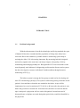
1.1
Problem background
With the advancement of medical technologies and living standard, the span
of human life has been extended and the population of living alone elders have
increased. Due to this situation, a portable intensive monitoring system help in
assisting the elders’ life is becoming important. By measuring both the biosignals
and activity signals at the same time can help to improve the quality of life by
maintaining and managing healthy life. Biosignal like ECG has been studies as the
most frequently used indicator for diagnosing cardiovascular diseases and a system
has been developed to measure individuals’ health condition through intensive
monitoring of ECG[1].
The holters system is among the first group to stand out for developing real
time ECG monitoring system[2]. This system is utilized by placing electrodes on the
patient’s chest and these electrodes are attached to the holter. A tape will be
implemented to record a continuous ECG for 24 or 48 hours after the patient is sent
home and goes back to normal life. After that time, the holter is removed and the
tape is analyzed. A physician will see each of the patient’s hearts beats and if
abnormal beats or rhythms occurred during that period, they would be identified by
the physician.
2
Medtronic Reveal Insertable Loop Recorder is also a sophisticated device
which allows up for 14 months recording of ECG episodes[3]. With that device, in
case the user experiences a fainting episode, for example, after waking, the user can
activate a button in a hand held device and a physician can analyze the stored
information a posteriori and determine whether the fainting episode was caused by
an abnormal heart rhythm.
Besides, there is also other system developed that gives warning in case the
heart has a problem such as arrhythmic pulse [4]. This system is capable of
monitoring patient’s heart condition continuously and in case happening an event, it
sends a warning to the doctor in a remote place. When that event happen, this
equipment can send a message immediately to the doctor in a remote place by using
wireless personal area communication technology and GPRS mobile phone
communication technology.
While the Jovanov proposed a health monitoring system using WBAN for
monitoring biosignals and activity signals [5]. This system was designed to monitor
biosignals and activity signal while the subject is moving. The system uses two
acceleration sensors to measure activity signal, and has a 1 channel bioamplifier to
measure the patient’s heart condition.
In comparison, my developed system measures ECG signal using 3 lead
cardiac monitoring system in order to get more accurate information on the patient’s
heart condition.
1.2
Alternative solution
Among the novel applications that can be supported by the new capabilities
of mobile handsets, those related with health care and telemedicine are gathering a
3
growing expectation, because of their social relevance and the huge potential market
represented by the ageing population of developed countries[6].
Among the PDAs used in the research as a monitoring device, J.M. CanoCarcia proposed using the Linux operating system as application framework for the
PDA and Desktop/Server computer [7]. She choose HP IPAQ H3970 PDA phone as
her portable monitoring device. However, this system required the PCMCIA data
acquisition card be connected to a PDA to build her portable data acquisition system
and the PCMCIA acquisition cards are expensive for mass production. Again, the
biosignal sensor device in this system is required to connect to PDA.
Besides, Jimena Rodriguez, Alfredo Goni, and Arantza Illarramendi proposed
the IPAQ Pocket PC (using MOLEC architecture) [8]. This is due to the MOLEC
architecture is not only capable of storing the ECG signal, but also it is an embedded
real-time system that captures, process, detects, analyzes and notifies possible
dangerous abnormalities. Furthermore, the research shows that MOLEC has the
lowest error of 3.581% in classifying beats and it also classifies rhythms.
Martin Ekstrom in his thesis entitled Small wireless ECG with Bluetooth
communication to a PDA recommend the PDA running the window mobile 5.0 and
at the same time be able to run LabView 8.0 for pocket PC[9]. LabView 8.0 is a
platform developed by National Instrument for graphical programming for
instrument communication. Besides, this PDA must support Bluetooth, Virtual Serial
Port Support and WIDCOMM Bluetooth driver (BTW-CE 1.4).
However, the PDA used in this project is based on Android operating system.
The reason to choose Android as the mobile operating system to develop this
application is the existence of an expanding collection of free development tools
such as a debugger, libraries, a handset emulator, documentation, sample code,
tutorials, support libraries and open source projects. Besides, the phone features also
include camera, Wi-Fi and Bluetooth which suite in this project. By using the
Bluetooth and ZigBee wireless communication technology, we can transfer data
easily between transmitter, wireless converter, computer and PDA which made the
whole system more mobility. Furthermore, the Android phones are becoming more
4
popularity and compete against the Apple iPhone in the US market and the market
analyst have predicted Android would overtake the iPhone in sales by 2012[10].
Currently, there is no research carry out on developing an application in Android
PDA phone in order to plot ECG signal and display heart rate pulse value and
becoming one of the innovation of this project.
1.3
Objective and scope
The objective of this project is to develop an application in Android PDA
phone in order to plot real-time ECG signal and display heart rate pulse value using
Bluetooth wireless communication technology. From this application, a real time
ECG signal and heart rate pulse value will be displayed.
While the scopes of this project are using the 3 lead cardiac monitoring
system, Android PDA phone as a monitoring device and Bluetooth serves as data
transferring protocol between computer and PDA.
For the expected result, a line graph is implemented to connect all the ECG
data points in order to plot the ECG signal. Besides, an integer will be located at
center of the PDA screen to display the heart rate pulse value.
5
1.4
Methodology
1.4.1
Work flow
The work flow of the project had been divided into several stages. The
implementation and work flow of the project are summarized into the flow chart as
shown in Figure 1.1.
Figure 1.1 Work Flow
6
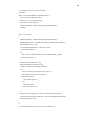
1.4.2
Block diagram
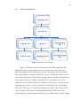
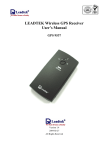
Figure 1.2 Block diagram
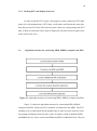
Figure 1.2 shows the developed system is consisted of 4 main parts. The
MDIzb which act as a transmitter to send the ECG data to MDIzb. MDIzb acts as
wireless converter to convert the ZigBee ECG data to Bluetooth ECG data. At the
same time, computer will acts on receive the Bluetooth ECG data and transfer those
data to PDA. The computer is used as a medium to communicate between MDIzb
and PDA due to the pairing problem in MDIzb. MDIzb does not require any pairing
code for paring purpose. However, PDA did require pairing code before data
transferring is allowed. After receiving ECG data from computer, the PDA
application will plot ECG signal and display heart rate pulse value.
7
1.4.3
Gantt chart
Figure 1.3.1 Gantt chart for Semester 1
Figure 1.3.1 shows the Gantt chart for 1st semester. During that time, I study
some information regarding available PDA phones in the market suitable for working
with Bluetooth data transferring, compatible with the developed monitoring system,
available tools and necessary APIs to develop an application in PDA phone. Finally,
the Android PDA phone (HTC Magic) is choose as a monitoring device. In order to
develop an application in this PDA phone, Java programming language is needed and
I started to learn this programming language. After knowing some basic of Java
programming language, I begin to learn to program simple applications by using
Eclipse Galileo software. This software allows me to test application on emulator
without the need to test on real PDA phone. Then I started to develop video
recording application. I successfully developed this application and the recorded
video is saved in the SD card.
8
Figure 1.3.2 Gantt chart for Semester 2
Figure 1.3.2 shows the Gantt chart for 2nd semester. During 2nd semester, I
started to develop Wi-Fi application. This application works on enable the Wi-Fi
without going through the setting. Again, this application can connect to the previous
remembered hotspot automatically. After finishing Wi-Fi application, I started to
work on Bluetooth application. This application required pairing the MDIzb before
trying to connect on each other for the data transferring. Due to the primitive
Bluetooth used in MDIzb, this device does not provide pairing code and lead to the
pairing problem. So, a computer is choose as a medium to connect the MDIzb and
PDA via Bluetooth. A program has been developed to solve this problem on data
transferring between these 2 devices. Finally, all the applications which had been
developed beforehand are integrate into single application for user friendly purpose.
1.4.4
Resource
The main system is consisted of 4 main parts which are MDIz, MDIzb,
computer and Android PDA phone. The MDIz is using the 3 lead cardiac monitoring
system. This 3 lead system is based on Einthoven triangle. There are 3 skin
electrodes used in this system and the color codes are based on IEC. The red
electrode is for the right arm, yellow electrode is for the left arm and the black
9
electrode is for the right leg and thus forming a triangle. Figure 1.4 shows the
characteristics of MDIz.
Figure 1.4 Characteristics of MDIz
The MDIzb acts on convert the ZigBee ECG data to Bluetooth ECG data.
The Bluetooth interface build in this device does not required paring code and lead to
low security that allow anyone to access the data. Figure 1.5 shows the
characteristics of MDIzb.
Figure 1.5 Characteristics of MDIzb
10
Besides, the Android PDA phone is equipped with a Qualcomm MSM7200A,
528 Mhz processor, 288MB RAM and 512 ROM and coming with firmware version
1.6. This firmware version does not allow the developers to develop Bluetooth
application. Due to this problem, the firmware has been upgraded to unofficially
Éclair version 2.1. Although this firmware version allow the developers to develop
their Bluetooth application, but this firmware is not stable as compare to version 1.6
and officially new firmware version 2.1 is estimated to release in mid of 2010. Again,
this PDA phone has the general features such as camera, Wi-Fi and Bluetooth which
suite in this project.
The computer acts as a medium to communicate MDIzb and PDA. The
software used to communicate between these 2 devices is BlueSoleil 6.0 trial version
and the computer must support Bluetooth. BlueSoleil 6.0 trial version enables the
user to connect more than 2 Bluetooth devices at the same time.
11
CHAPTER 2
LITERATURE REVIEW
2.1
Introduction
Due to the advancement of technology in the field of mobile communications,
it lead to the deployment of packet data services over cellular mobile systems and
giving support for the deployment of new applications. At the same time, the
increase of the number of subscribers to mobile telephony systems has lead to the
proliferation of a wide range of wireless handsets. An increasing effort has been
devoted to the development of low power and high performance embedded
microprocessors with multimedia capabilities due to the popularization of such
devices has promoted a growing interest to continuously improve their features and
performance. Similarly, a significant enhancement of the development tools and
software support for these platform has been achieved. As a result. PDA and
Smartphone delivering capabilities comparable to those exhibited by desktop
computers including wireless internet access and multimedia support. These
handheld devices are provided with an operating system to support application
software and make it easy for the development. This framework opens the door to the
emergence of a wide range of innovative applications that can be supported by
current PDAs and Smartphone, devices which are becoming more and more popular
and familiar for standard users[7].
12
Due to the new capabilities and features of mobile handsets, it becoming
more popular in the field of health care and telemedicine. For example, J.M. CanoCarcia proposed using the Linux operating system as application framework for the
PDA and Desktop/Server computer [7]. She choose HP IPAQ H3970 PDA phone as
her portable monitoring device. However, this project choose Android PDA phone as
a portable monitoring device.
2.2
Introduce Android
Android is a mobile operating system that uses a modified version of the
Linux kernel. It was initially developed by Android Incorporated, a firm later
purchased by Google, and lately by the Open Handset Alliance. It allows developers
to write managed code in the Java programming language.
The Android SDK provides the tools and APIs to start developing
applications on the Android platform. Besides, it also includes a comprehensive set
of development tools such as debugger, libraries, a handset emulator, documentation,
sample code, and tutorials.
Furthermore, Android offers developers to develop extremely rich and
innovative applications by providing an open development platform. Developers are
free to take advantage of the device hardware, access location information, run
background services, set alarms, add notifications to the status bar, and others.
Besides, developers can gain full access to the same framework APIs used by
the core applications. This application architecture is designed to simplify the reuse
of components. For example, any application can publish its capabilities and any
other application may then make use of those capabilities.
13
2.3
Eclipse Galileo
Eclipse is a multi-language software development environment consist an
IDE and an extensible plug-in system. The primarily written language is Java and
can be used to develop Java application. By means of the available plug-ins, it also
can be written in different programming language such as C, C++, COBOL, Python,
Perl, PHP, and others.
Furthermore, Eclipse employs plug-ins in order to provide all of its
functionality on top of the runtime system as compare to some other applications
where functionality is typically hard coded.
Figure 2.1 Eclipse Galileo Interface
14
Figure 2.2 Handset Emulator Interface
2.4
ECG
ECG is a very important means for non-invasive diagnosis. It is one of biopotential signals, with amplitude of several mV and frequency less than 250Hz. In
the early 1960s in the U.S.A, the research on ECG system design and signal
processing had started. Starting from that time, there have been researches on
designing hardware such as multi-channel ECG for automatic diagnosis, Holter ECG
that monitors patients with cardiac disorder for 24 hours a day, stress ECG that
diagnose cardiac disorders under exercise stress, and developing accurate
algorithms[11].
15
2.4.1
Electricity of the heart
The electrodes attached to the surface of the body can detect the contraction
of any muscle. Basically, the heart has four chambers. But from the electrical point
of view, it can be thought of having only two due to the two atria contract together
and then the two ventricles contract together. Figure 2.3.1 shows cardiac conduction
system.
Figure 2.3.1 Cardiac conduction system
The electrical activity of the heart originates in the SA node, located in the
wall of the right atrium. Then, the impulse is increasingly spreads through the right
atrium to the AV node. After some time at AV node, the impulse spreads slowly
through the bundle of his, the bundle branches, the Purkinje network, and finally the
ventricular muscle. The first area of the ventricular muscle to be activated is the
inter-ventricular septum, which activates from left to right. Lastly, the impulse
divides into the Purkinje network of fibers that proceed vertically to the surface of
the heart [12].
16
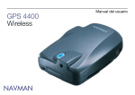
Figure 2.3.2 Points and elements of ECG signal
2.4.2
Electrocardiography Signals
The ECG waveform is divided into P, Q, R, S, T and U elements [13]. The P
wave corresponds to atrial depolarization that shows contraction of both left and
right atria. Normal duration of P wave is between 0.06 to 0.12 seconds. The QRS
complex represents depolarization of the ventricles. The duration of the QRS
complex shows how long excitation takes to spread through the ventricles and must
less than 0.1 seconds for normal ventricles contraction. The T wave represents
ventricles repolarization which setting up the cardiac muscle for another contraction.
Sometimes it will follow by U wave that represents the purkinje fibers repolarization.
The PR interval is the conduction time required for an electrical impulse to be
conducted from the atria to the ventricles. The duration is normally 0.12 to 0.20
seconds and it is important to indicate heart block problems. The QT interval is
measured from the beginning of the QRS complex to the end of the T wave. A
normal QT interval is about 0.40 seconds. The ST segment connects the QRS
complex and the T wave. It represents the measured time between ventricular
17
depolarization and the beginning of ventricular repolarization which normally last
about 0.08 seconds. The normal period of one cardiac cycle is between 0.6 seconds
to 1.0 seconds, which it represents the heart rate or the number of heart BPM. Thus,
the heart rate for normal rhythm is between 60 to 100 BPM. The ECG strips is best
interpreted from lead II or lead V1 which the lead shows the most clearly rhythm of
the heart according to Einthoven’s Triangle [14]. Figure 2.3.2 shows normal ECG
signal from the standard lead II.
2.5
Bluetooth wireless communication technology
Bluetooth, also known as the IEEE 802.15.1 standard is based on a wireless
radio system designed for short-range and cheap devices. This range of applications
is known as WPAN. The two connectivity topologies defined in Bluetooth are
piconet and scatternet. A piconet is a WPAN formed by a Bluetooth device serving
as a master in the piconet and one or more Bluetooth devices serving as slaves. A
frequency-hopping channel based on the address of the master defines each piconet.
All devices participating in communications in a given piconet are synchronized
using the clock of the master. Slaves communicate only with their master in a pointto-point fashion under the control of the master. The master's transmissions may be
either point-to-point or point-to-multipoint. Besides in an active mode, a slave device
can be in the parked or standby modes so as to reduce power consumptions. A
scatternet is a collection of operational Bluetooth piconets overlapping in time and
space. Two piconets can be connected to form a scatternet. A Bluetooth device may
participate in several piconets at the same time, thus allowing for the possibility that
information could flow beyond the coverage area of the single piconet. A device in a
scatternet could be a slave in several piconets, but master in only one of them[17].
The maximum signal rate for the Bluetooth is 1Mb/s and the nominal range for
detecting the Bluetooth is 10m.
18
2.6
ZigBee wireless communication technology
ZigBee also known as IEEE 802.15.4 defines specifications for LR-WPAN
for supporting simple devices that consume minimal power and typically operate in
the POS of 10m. ZigBee provides self-organized, multi-hop, and reliable mesh
networking with long battery lifetime [15,16]. Two different device types can
participate in an LR-WPAN network: a FFD and a RFD. The FFD can operate in
three modes serving as a PAN coordinator, a coordinator, or a device. An FFD can
talk to RFDs or other FFDs, while an RFD can talk only to an FFD. An RFD is
intended for applications that are extremely simple, such as a light switch or a
passive infrared sensor. They do not need to send large amounts of data and only
associate with a single FFD at a time. Consequently, the RFD can be implemented
using minimal resources and memory capacity. After an FFD is activated for the first
time, it may establish its own network and become the PAN coordinator. All star
networks operate independently from all other star networks currently in operation.
This is achieved by choosing a PAN identifier, which is not currently used by any
other network within the radio sphere of influence. Once the PAN identifier is
chosen, the PAN coordinator can allow other devices to join its network. An RFD
may connect to a cluster tree network as a leave node at the end of a branch, because
it may only associate with one FFD at a time. Any of the FFDs may act as a
coordinator and provide synchronization services to other devices or other
coordinators. Only one of these coordinators can be the overall PAN coordinator,
which may have greater computational resources than any other device in the
PAN[17]. The maximum signal rate for the ZigBee is 250kb/s and the nominal range
for detecting the ZigBee is from 10m till 100m.
19
2.7
Wireless Medical Interface
There are 2 kinds of wireless medical interface which has been discussed in
this project; MDIz and MDIzb. MDIz is a device which acquires data from medical
device and transmits it out through Zigbee network. For the MDIzb, it coordinates
the Zigbee network as well as communicates with Medical Data Assistant through
Bluetooth network[19].
Figure 2.4 Block diagram of MDIz
Figure 2.5 Frame of MDIz
Figure 2.4 shows the block diagram of MDIz. Analog signal from medical
sensor is conditioned, digitized and processed by a processor. The data from
processor is converted to Zigbee and then transmitted out. The data is arranged in a
frame as shown in Figure 2.5. It consists of device ID, status, length of process, data
and checksum. The Zigbee module is bidirectional and MDIz can receive the
command through Zigbee module.
20
Figure 2.6 Block diagram of MDIzb
Figure 2.7 Frame of MDIzb
MDIzb coordinates the Zigbee network. It decides which medical device will
communicate to in that time and give them priority based their status. Figure 2.6
shows block diagram of MDIzb. It consists of Zigbee module, two processors, Dlatch, SRAM, and Bluetooth module. Data from MDIz is received by Zigbee module
and processed by processor 1. Delay may ignore the data. To overcome this matter, a
256kb SRAM is added as a data buffer. The data is then sent to processor 2 to add a
frame as shown in Figure 2.7 before transmitted out by Bluetooth module. Bluetooth
data is acquired by mobile data assistant. The Bluetooth module is bidirectional and
MDIzb can receive the command through Bluetooth module.
21
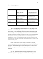
2.8
Solution comparison
Features
HTC Magic
HP IPAQ H3970 PDA
PDA connected wireless via
PDA connected physically to
MDIzb, MDIz and
PCMCIA data acquisition
computer.
card and biosignal sensors.
Computer is required as a
PCMCIA data acquisition
medium to communicate
card and PDA require
MDIzb and PDA.
PCMCIA expansion sleeve.
3. Mobile operating
Android operating system.
Linux operating system.
system
(open source project)
(open source project)
4. Tools
ADT Plug-in for Eclipse
COMEDI (support data
1. Portability
2. External Support
acquisition)
Table 1 Comparison between HTC Magic and HP IPAQ H3970 PDA
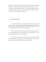
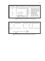
Table 1 shows the solution comparison between HTC Magic and HP IPAQ
H3970 PDA. For the HP IPAQ PDA, this project is based on J.M. Cano-Garcia team
project entitled “A PDA based portable wireless ECG monitor for medical personal
area networks”[7]. In term of portability, all the devices are connected wirelessly to
each other in my project while the J.M. Cano–Garcia team project required PCMICA
data acquisition connected physically to the device as well as biosignal sensors.
Although in my project all the connected devices are connected wirelessly, but this
system limit to the home and hospital usage and limit the mobility as compare to J.M.
Cano-Garcia team project.
Besides, for the external support, computer is required to be one of the
element in my project and lead to the immobility. However for the J.M. Cano-Garcia
team project, the PDA need to have PCMCIA expansion sleeve in order to connect
PCMCIA data acquisition card. This card is expensive for the purpose of mass
production.
Next, HTC Magic support android operating system while the HP IPAQ
H3970 PDA support Linux operating system and both of this operating system is
22
open source project. Furthermore, ADT is a plug-in for the Eclipse IDE that is
designed to give a powerful, integrated environment in which to build Android
applications. At the same time, ADT also extends the capabilities of Eclipse to let the
developers quickly set up new Android projects, create an application UI, add
components based on the Android Framework API, debug applications using the
Android SDK tools and even signed APKs in order to distribute application. As
compare with J.M. Cano–Garcia team project, COMEDI is a tools that comprises a
collection of drivers for a variety of common data acquisition boards, as long as a
development library which offers a common programming interface to grant
acquisition hardware interchangeability[7].
23
CHAPTER 3
DESIGN AND IMPLEMENTATION
3.1
Design specification
3.1.1
GUI for video recording, Wi-Fi and Bluetooth applications
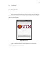
The main layout for GUI shows UTM logo and a button. By clicking the
button, it will load to the second layout. For the second layout, it has a spinner which
enable the user to choose a connection either video recording, Wi-Fi or Bluetooth
applications. By choosing the desired selection, the user need to click a button to
proceed each application.
3.1.2
Video Recording application
In order to start recording video, the user need to touch the screen and stop
recording by touch again the screen. The recorded video file format is mp4 and save
in SD card.
24
3.1.3
Wi-Fi application
The check box widget is used to enable the Wi-Fi by checking the check box.
After enabling the Wi-Fi, it will automatically connected to the remember hotspot.
3.1.4
Bluetooth application
3.1.4.1 PDA Bluetooth application
User need to active their Bluetooth setting to enable Bluetooth. The limitation
of this application is the user need to hardcoded their computer Bluetooth MAC
address into application in order to communicate with each others.
3.1.4.2 Computer Bluetooth application
In order to communicate between PDA and MDIzb, BlueSoleil 6.0 trial
version is used to connect these 2 devices via computer. After connecting to the
computer, they are connected to the different COM port instead of the same COM
port. So, a program that is capable of transferring data from one COM port to
different COM port is needed to communicate these 2 devices.
25
3.1.5
Plotting ECG and display heart rate
In order to plot the ECG signal, a line graph is used to connect the ECG data
points. For each transmission of ECG data, it will redraw itself and at the same time
keep the previous ECG data. The heart rate pulse values are coming along with ECG
data. A draw text function will be used to display the real time heart rate pulse value
at the center of the view.
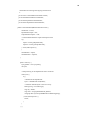
3.2
Algorithm structure for connecting MDIz, MDIzb, computer and PDA
Figure 3.1 Algorithm structure for connecting MDIz, MDIzb, computer and PDA
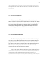
Figure 3.1 shows the algorithm structure for connecting MDIz, MDIzb,
computer and PDA. Firstly, the ECG simulator is connected to the MDIz. The ECG
simulator acts as replacement for the human body in order to get the accurate result
for plotting and display heart rate pulse value. Secondly, switch on both the MDIz
and MDIzb devices. Next, connect the MDIzb and PDA via BlueSoleil 6.0. They are
26
connecting to each other when you notice each of the device connected by a dotted
line shows in BlueSoleil interface. Again, the computer Bluetooth application is
activated by clicking the “start” button and the ECG data values will be shown in a
text box. This is to ensure that the MDIzb is sending the data to PDA. Lastly, start
the PDA Bluetooth application and the ECG data will be plotted and heart rate pulse
value will be displayed.
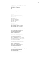
3.3
Main Flow chart
Figure 3.2 Main flow chart
Figure 3.2 shows the main flow chart. First of all, the GUI for the video
recording, Wi-Fi and Bluetooth applications are developed to give an overview of the
application structure. Next, the video recording application is developed. This
application works on touch the screen to start recording and touch again to stop
recording. The recorded video is saved in the SD card. While the Wi-Fi application
allows the user to enable the Wi-Fi within application and connect to the hotspot
automatically. For the Bluetooth application, there are 2 parts which are on the PDA
and computer. The PDA Bluetooth application work on communicate with the
27
computer to receive ECG data from MDIzb while the computer Bluetooth
application work as transferring data from one COM port to the other COM port. In
order to plot ECG, a line graph is used to connect all the ECG data points.
3.4
Sub flow charts and explanation
3.4.1
Develop GUI for video recording, Wi-Fi and Bluetooth application
The main layout is designed as putting a UTM logo, a “start” button and
some texts such as PDA intensive monitoring and welcome. The button is used to
load the second layout.
After the user click on the start button, the second layout appeared. There will
be a spinner and a “click on setting” button. The spinner create a list of connection
such as Bluetooth, Wi-Fi, and Video Recording. When the user click on the spinner,
it will display the list to allow the user to select their desired connection. After the
user has choose their desired connection, they need to click on “click on setting”
button to proceed desired application.
3.4.2
Develop video recording application
When the user select video recording application, there will display a new
layout with a square surface and 4 radio buttons. The square surface is for the video
recording while the 4 radio buttons are implemented for future usage such as for
sending the particular video to doctor. When the user touch on the square surface, the
28
video recording activity will be started. In order to stop recording, the user need to
touch again the square surface and at the same time, the recorded video will be save
in the SD card.
3.4.3
Develop Wi-Fi application
When the user select Wi-Fi application, there will be a check box and a
button. The check box is used to enable or disable the Wi-Fi while the “Next” button
is used to load the next layout. After user click on the button, a new layout appeared
by a “Refresh” button. By clicking on the “Refresh” button, it will automatically
connected to the remember hotspot. After connecting the hotspot, there will be 2
texts which display the IP address and SSID for the connected hotspot.
3.4.4
Develop Bluetooth application
The Bluetooth require pairing with the remote devices before connecting on
each others. For PDA Bluetooth application, the user need to manually enable and
pairing the Bluetooth device before starting to communicate with computer. The
MAC address for the computer is hardcoded into the PDA Bluetooth application. If
PDA and computer already pairing with each others, they will automatically
connecting each other when this application is launched.
While for the computer Bluetooth application, when the MDIzb and PDA are
connected to the computer, they are connected to the different COM port. Different
COM port does not allow transferring data between these two devices. An
application has been developed to solve this problem by allowing specific COM port
29
to write to different COM port. The GUI shows 2 buttons, one is “start” button and
the other one is “stop” button. When MDIzb and PDA are connected to computer, by
clicking the “start button” allow transferring of ECG data from one COM port to
other COM port and “stop” button for stopping transferring of data. This program is
developed using C sharp programming language and visual studio 2008.
3.4.5
Plot ECG and display heart rate pulse value
A new class will be implemented for plotting ECG signal. An ECG simulator
will be used as replacement for the human body in order to get accurate result. The
ECG wave sample points are transmitted continuously with 50, 100 or 300 bytes per
second, according to the user’s last command. The curve sample points lie between 0
and 246.
For every single transmission of ECG data, a handler will be implemented to
handle the message and pass the ECG data to GraphView class and invalidate
function for redrawing the view. GraphView class is implemented as a layout for
plotting the ECG data. This class is being called for every single transmission of
ECG data.
A drawline function is used to plot the ECG signal. In order to draw a line,
there must be at least 2 points and this function have four arguments, starting x y
point and ending x y point. After plotting from the first point to second point, the
second point need to be save as the starting point and third point as the ending point
and continuously.
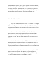
For the heart rate pulse value, it values are integrated along with the ECG
data. The values which are higher than 246 (0xF6) are used for marking the
following byte as a new data values according to the following definition in figure
3.3. Besides, example of data stream received shows in figure 3.4.
30
Figure 3.3 Definition of data stream sent by the module
Figure 3.4 Example of a received data stream at the host side
31
3.5
Source code structure
androidone class
Activity2 class
newgraph class
WiFi class
VideoRecording
class
GraphView class
HelloAndroid class
CamcorderPreview
class
Figure 3.5 Source code structure
Figure 3.3 shows the source code structure for the PDA application. The
androidone class is for the main layout class. After the user click on the “start”
button, the application will load to the Activity2 class which is the second layout.
This layout implement a spinner which have a list of 3 connections. When the user
select on the Bluetooth, it will load the newgraph class for the Bluetooth application.
The newgraph class has a handler to handle the ECG data and pass the data to
GraphView class to plot the graph. The GraphView class serves as a layout for the
newgraph class. However, if the user select on WiFi from the list, it will load the
WiFi class. This class serves enabling or disabling the WiFi. After clicking on the
“Next” button, it will continue to load HelloAndroid class. This class acts on
connecting the remember hotspot automatically by clicking on the “Refresh” button.
32
Besides, if the user select VideoRecording, it will load VideoRecording class. This
class acts as starting or stopping video recording and implement the
CamcorderPreview class as the layout.
3.6
Detail source code and explanation
3.6.1
Declaring Layout
The layout is the architecture for the user interface in an Activity. It defines
the layout structure and holds all the elements that appear to the user. There are two
ways of declaring the layout. First, declare user interface elements in XML. From
this, Android provides a straightforward XML vocabulary that corresponds to the
View classes and subclasses, such as for those widgets and layouts. The second
method is instantiate layout elements at runtime. The application using this type of
layout can create View and ViewGroup objects and manipulate their properties
programmatically[17].
3.6.2
The AndroidManifest.xml file
Every single Android application must have an AndroidManifest.xml file in
its root directory. This manifest presents an essential information about the
application to the Android system, information the system must have before it can
run any of the application’s code. The android manifest files does the following
things[18].
33
1. It names the Java package for the application. The package name serves as a
unique identifier for the application.
2. It describe the components of the application such as activities, services,
broadcast receivers, and content providers that the application is composed of.
It names the classes that implement each of the components and publishes
their capabilities. These declarations let the Android system know what the
components are and under what conditions they can be launched.
3. It determines which processes will host application components.
4. It declares which permissions the application must have in order to access
protected parts of the API and interact with other applications.
5. It also declares the permissions that others are required to have in order to
interact with the application's components.
6. It lists the Instrumentation classes that provide profiling and other
information as the application is running. These declarations are present in
the manifest only while the application is being developed and tested; they're
removed before the application is published.
7. It declares the minimum level of the Android API that the application
requires.
3.6.3
Source code detail
3.6.3.1 Implement Android button
Button next = (Button) findViewById(R.id.Next);
next.setOnClickListener(new View.OnClickListener() {
public void onClick(View view) {
Intent myIntent = new Intent(view.getContext(),Activity.class);
startActivityForResult(myIntent, 0);
}
34
});
The android widget button is declared in xml layout and it id is “Next”. When
the user click on the button, it will move to Activity class.
3.6.3.2 Implement Android spinner
final Spinner spinner1 = (Spinner) findViewById(R.id.spinner);
ArrayAdapter adapter = ArrayAdapter.createFromResource(
this, R.array.connection, android.R.layout.simple_spinner_item);
adapter.setDropDownViewResource(android.R.layout.simple_spinner_dropd
own_item);
spinner1.setAdapter(adapter);
//create array in res/value/arrays.xml
<resources>
<string-array name="connection">
<item>Bluetooth</item>
<item>WiFi</item>
<item>VideoRecording</item>
</string-array>
</resources>
The first line declare the spinner by it id spinner. The createFromResource()
method then creates a new ArrayAdapter, which binds each item in the string array to
the initial appearance for the Spinner. The R.array.connection ID references the
string-array defined above and the android.R.layout.simple_spinner_item ID
references a layout for the standard spinner appearance, defined by the platform.
Then setDropDownViewResource(int) is called to define the appearance for each
item when the widget is opened (simple_spinner_dropdown_item is another standard
layout defined by the platform). Finally, the ArrayAdapter is set to associate all of its
items with the Spinner by calling setAdapter(T).
35
3.6.3.3 Implement video recording application (refer to Appendix G and H)
mSurfaceView = (CamcorderPreview) findViewById(R.id.surface_camera);
mSurfaceView.setOnTouchListener(new OnTouchListener() {
public boolean onTouch(View view, MotionEvent event) {
if (event.getAction() == MotionEvent.ACTION_DOWN) {
if (recording) {
mSurfaceView.getRecorder().stop();
mSurfaceView.getRecorder().release();
onStop();
onDestroy();
} else {
recording = true;
mSurfaceView.getRecorder().start();
}
return true;
}
return false;
}
});
The video recording class implement the CamcorderPreview class as the
surface to record video. The default value for the recording is false. When the user
touch the screen, it will start video recording and touch again to stop video recording.
For the onDestroy() call method is to destroy the video recording activity.
3.6.3.4 Implement Wi-Fi application (refer to Appendix E and F)
mWm = (WifiManager) this.getSystemService(Context.WIFI_SERVICE);
if (mWm.isWifiEnabled()) {
cb.setChecked(true);
36
cb.setText("Wifi is : enabled");
} else {
cb.setChecked(false);
cb.setText("Wifi is : disabled");
}
public void onCheckedChanged(CompoundButton buttonView, boolean
isChecked) {
if (isChecked) {
if (mWm.setWifiEnabled(true))
cb.setText("Wifi is : enabled");
else {
cb.setChecked(false);
cb.setText("Attempt to enable failed");
}
} else {
if ( (mWm.setWifiEnabled(false)))
cb.setText("Wifi is : disabled");
else {
cb.setChecked(true);
cb.setText("Attempt to disable failed");
}
}
}
The WiFi class act as enable or disable the Wi-Fi service. The first line shows
the mWm is registered with Wi-Fi service. The first if statement is to check whether
the Wi-Fi is already enable or disable and set the check box to true or false
accordingly. At the same time, the text view will shows whether the Wi-Fi is enable
or disable. The second if statement implement if the check box is checked, it will
enable the Wi-Fi and vice versa.
37
3.6.3.5 Implement Bluetooth application (refer to Appendix C)
public void connect()
{
mBluetoothAdapter = BluetoothAdapter.getDefaultAdapter();
BluetoothDevice device =
mBluetoothAdapter.getRemoteDevice(address);
BluetoothSocket tmp = null;
// Get a BluetoothSocket for a connection with the
// given BluetoothDevice
try {
tmp = device.createRfcommSocketToServiceRecord(MY_UUID);
} catch (IOException e) {
}
BluetoothSocket mmSocket = tmp;
mBluetoothAdapter.cancelDiscovery();
// Make a connection to the BluetoothSocket
try {
// This is a blocking call and will only return on a
// successful connection or an exception
mmSocket.connect();
} catch (IOException e) {
try {
mmSocket.close();
} catch (IOException e2) {
}
}
}
In order to initiate a connection with a remote device(a device holding an
open server socket), the BluetoothDevice object representing remote device must be
38
obtain first. By using the BluetoothDevice, the BluetoothSocket can be obtain by
calling createRfcommSocketToServiceRecord (UUID). This will initializes a
BluetoothSocket that will connect to the BluetoothDevice. The UUID passed here
must match the UUID used by the server device. The connection can be initiate by
calling the connect(). By calling this, the system will perform an SDP lookup on the
remote device to match the UUID. if the lookup is successful and the remote device
accepts the connection, it will share the RFCOMM channel to use during the
connection.
3.6.3.6 Plot ECG and display heart rate pulse value(refer to Appendix C and D)
for (; m <= secondsLeft ; m++){
rat[m] = (readint123-128)/diff;
h[m] = graphheight *rat[m];
lasth[m] = h[m];
}
for (int j=0 ; j <= secondsLeft; j++) {
canvas.drawLine(((j) * colwidth) + (horstart + 1) + halfcol, (border - lasth[j])
+ graphheight, ((j+1) * colwidth) + (horstart + 1) + halfcol, (border - h[j+1])
+ graphheight, paint);
lasth[j] = h[j];
}
In order to plot ECG graph, drawLine() is called. The drawLine() has four
arguments, starting from initial x y point to end x y point. A line can only be draw if
at least 2 points exist to form a line. The variable m is used for counting how many
points being pass by or counting on how many time the onDraw() was called.
However, the secondsLeft variable state for each single transmission of ECG data.
By doing looping on drawLine(), every single data pass by will enable the current
and pass point values being plotted continuously.
39
Handler myViewUpdateHandler = new Handler(){
/** Gets called on every message that is received */
@Override
public void handleMessage(Message msg) {
switch (msg.what) {
case newgraph.MESSAGE_READ:
byte[] bytes = (byte[]) msg.obj;
String readMessage123 = new String(bytes);
int readint = Integer.parseInt(readMessage123.trim());
if (readint !=0 && readint <= 246){
mySecondsPassed++;
myView.updateSecondsPassed1(readint);
myView.updateSecondsPassed(mySecondsPassed);
}
if (mySecondsPassed > 350){
mySecondsPassed=0;
}
myView.invalidate();
break;
}
super.handleMessage(msg);
}
};
Since the GUI need to be redraw for every single transmission of ECG data ,
a thread is needed to handle the data. The transmission data is in byte format and by
calling the Integer.parseInt() to change the data format to integer in order to plot the
graph. The ECG plotting points is within 0 and 246. This value need to be constantly
pass to the GraphView class to redraw the plot.
40
3.7
Casing photos
HTC Magic
laptop
Figure 3.6 Casing photos
41
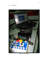
3.8
System photo
Figure 3.7 System photo
42
3.9
User Manual
3.9.1
PDA application
Before starting the PDA application, the user is asked to active the Bluetooth
setting. After being activated, user can start this application. Below shows the GUI
obtain from this application.
Figure 3.8 Main GUI
Figure 3.8 shows the main GUI for this application. User click on the
“START” button to proceed to next layout.
43
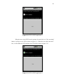
Figure 3.9 Second layout
Figure 3.9 shows the second layout for this application. There is a spinner and
two buttons. By clicking on the spinner, you may obtain the result as shows in
Figure 3.10.
Figure 3.10 Spinner
44
Figure 3.11 GUI for WiFi application 1
When the user select WiFi from the spinner list and click on “Click on setting”
button, it will go to new GUI as shows in figure 3.11. When the user check the check
box, it will enable the Wi-Fi and the next GUI will be shows in figure 3.12.
Figure 3.12 GUI for WiFi application 2
45
After the user click on “Next” button, it will go to the next GUI as shows in
figure 3.13.
Figure 3.13 GUI for WiFi application 3
In order to connect Wi-Fi hotspot, user is asked to click on “Refresh” button.
It will start to automatically connected to the remember hotspot. If the connection
had been obtain, the next GUI shows the connected Wi-Fi application in figure 3.14.
46
Figure 3.14 Connected WiFi GUI
Figure 3.14 also shows the IP and SSID address for the connected Wi-Fi
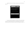
hotspot. However, when the user select VideoRecording from the spinner list and
click on “Click on setting” button, it will go to next GUI as shows in figure 3.15.
Figure 3.15 GUI for video recording application
The video recording is started by touching the screen and stopped recording
by touching again the screen. The recorded video is saved in the SD card.
47
Figure 3.15 also shows four radio buttons. These radio buttons are
implemented for future usage like sending the respective video for different doctor.
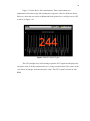
However, when the user select on Bluetooth from spinner list, it will go to next GUI
as shows in figure 3.16.
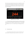
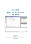
Figure 3.16 GUI for ECG plot
This GUI straight away will starting to plot the ECG signal and display heart
rate pulse value if all the connected device is ready to transfer data. The center of the
view shows an integer for heart rate pulse value. This ECG signal is based on 240
BPM.
48
3.9.2
Computer Bluetooth application
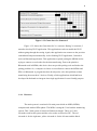
Figure 3.17 BlueSoleil 6.0 Interface 1
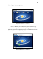
Figure 3.17 shows the GUI for BlueSoleil 6.0 interface. Initially, the user
need to active their computer Bluetooth module by clicking on the center “Ball”
shape button and searching for the Bluetooth devices. After searching for the remote
devices, it will shows the next GUI as in figure 3.18.
Figure 3.18 BlueSoleil 6.0 Interface 2
49
The next step required the user to do pairing before they can actually
connecting to each other. It will pop up a message asking user to key in a paring code
for the Android phone and the computer. The paring code enter must be the same for
each of these devices before they can started to connect each others. The figure also
shows the dotted line being connected to HTC Magic and MDIzb. This dotted line is
to ensure that they are currently connecting on each other. Now is it the time to run
the program developed using C sharp programming language.
Figure 3.19 GUI for computer Bluetooth application 1
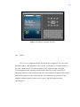
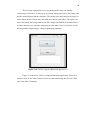
Figure 3.19 shows the GUI for computer Bluetooth application. The user is
asked to click on the “Start” button in order to start transferring data for one COM
port to the other COM port.
50
Figure 3.20 GUI for computer Bluetooth application 2
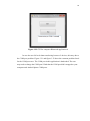
Figure 3.20 shows the GUI for successfully data transferring between 2
COM port devices. The text boss shows the data transferring values. This is to ensure
data is transferring between 2 COM ports. The “Stop” button is used to stop data
transferring between 2 COM port devices.
Figure 3.21 GUI for computer Bluetooth application 3
51
Figure 3.22 GUI for computer Bluetooth application 4
In case the user fail to do data transferring between 2 devices, this may due to
the COM port problem. Figure 3.21 and figure 3.22 show the common problem faced
for the COM port error. The COM port in this application is hardcoded. The user
may need to change the COM port if find that the COM port didn’t mapped to your
computer and Android phone COM ports.
52
CHAPTER 4
TEST RESULT AND ANALYSIS
4.1
Objective and scope of testing
The objective of the testing is to test whether the PDA application capable of
performing real time monitoring.
While the scope of testing is to test how long PDA application can perform
real time monitoring and plotting based on different BMP set by ECG simulator.
4.2
Functional testing
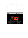
In order to plot real time ECG signal and display heart rate pulse value, firstly,
connect ECG simulator to MDIz and set it to 240 BPM. Secondly, switch on the
power of both these devices. After that, start the BlueSoleil 6.0 application and do
paring for the Android PDA phone with computer. Before that Android PDA phone
must active it Bluetooth module to let the BlueSoleil search for it device. MDIzb can
start to connect to computer without pairing. Now BlueSoleil interface will shows
53
both of these devices connected to the center of the view via dotted line. Next, start
on the computer Bluetooth applcition and clicking on the “Start” button to do data
transferring between one COM port to other COM port. Finally, launch the PDA
application and select the Bluetooth from the spinner list and figure 4.1 shows the
test result for 240 BPM.
Figure 4.1 ECG plot for 240 BPM
The orange color integer in the figure shows the heart rate pulse value. From
this figure, it may note that some spikes occurred below the “128” value. This graph
value is being set in order to obtain an acceptable ECG signal. Due to the limitation
of the PDA phone screen size, “128” value is being set as a starting point for the y
axis.
4.3
Performance testing
For the resolution, the direct AD converter values (0 to 255) for the y-axis
while the number of sample points send per second for the x-axis (Hz). For the
54
medium amplification stage (A1), the zero line of the ECG is at the middle of the AD
range (128). 1mV is equal to 100 steps. For example, “228” received as sample value
would equal to 1mV in the positive direction, “28” would be equal to 1mV in the
negative direction. For the high amplification stage (A2), this resolution is doubled.
For example, 228 related to 0.5mV while for the low amplification stage (A0), the
resolution is half. For example, 228 relates to 2mV.
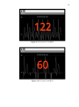
Besides, tests have been carry out according to different BPM set by ECG
simulator. The result are obtained as show in the following figures.
Figure 4.2 ECG plot for 180 BPM
55
Figure 4.3 ECG plot for 120 BPM
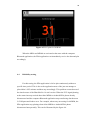
Figure 4.4 ECG plot for 60 BPM
56
Figure 4.5 ECG plot for 30 BPM
When the MDIz and MDIzb are activated at the same with the computer
Bluetooth application, the PDA application can immediately receive the data and plot
accordingly.
4.4
Reliability testing
For this testing, the PDA application is left to plot continuously without a
specific time period. This is due to the application most of the just can manage to
plot within 1 till 5 minutes and then stop accordingly. This problem occurred most of
the time because of the BlueSoleil 6.0 is trial version. When the ECG signal plotting,
at the same time may noticed that either MDIzb or Android PDA phone already
disconnected and the computer Bluetooth application stop transferring data between
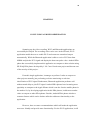
2 COM ports and lead to error. For example, when carry out testing for 60 BPM, the
PDA application stop plotting when either MDIzb or Android PDA phone
disconnected unexpectedly. This can be illustrated by the figure 4.6.
57
Figure 4.6 ECG plot for 60 BPM
So, for the recommendation, a fully compatible Bluetooth application is
needed in order to test the performance more accurately.
58
CHAPTER 5
CONCLUSION AND RECOMMENDATION
Summing up, the video recording, Wi-Fi and Bluetooth applications are
successfully developed. The recording video can be save in the SD card, Wi-Fi
application enable the user to enable Wi-Fi and connect to remember hotspot
automatically. While the Bluetooth application is able to receive ECG data from
MDIzb and plot the ECG signal and display the heart rate pulse value. Android PDA
phone has successfully implement this application as compare to other solution using
HP IPAQ PDA phone developed by J. M. Cano-García team project and become one
of the novelty of this project .
From this single application, it manages to perform 3 tasks as compare to
other projects normally just performing real time monitoring or real time
classification of ECG signal. Furthermore, Bluetooth application performs well
without much delay to plot ECG signal. Android PDA phones have becoming more
popularity as compare to the Apple iPhone which is one the favorite mobile phone in
the market. So, by developing application in this PDA phones, it adds more market
value as compare to other PDA phones. Besides, Android PDA phones also have
common features which can be further utilized to add more functionality to the
application.
However, here are some recommendations which will made the application
more user friendly and provide more functionality. For the Wi-Fi application, it will
59
be more user friendly if the application can search for available hotspot and display it
in spinner or list view. Again, by using the Wi-Fi wireless communication
technology, the Android PDA phone can act like a server to transfer ECG data from
one PDA to other PDAs and computers. This is called as Wi-Fi ad hoc network.
From this, it can add more functionality to the Wi-Fi application instead just
connected to the Wi-Fi hotspot. Besides, for the Bluetooth application, it is
recommended that the ECG plot can be save continuously instead just plotting it. The
ECG plot later can be used as a tool for doctor to analyze the patient heart conditions.
A fully compatible Bluetooth software is required in order to provide maximize
operating time for the PDA application.
60
REFERENCES
[1] S.J. Jose J, C.F. David, S.P. Luis, A. Mateo, “A microcontroller-based portable
electrocardiograph recorder”, IEEE Transactions on Biomedical Engineering, Sep
2004, pp.1686-1690.
[2] P. Farreras and C. Rozman, Medicina Interna, 13rd ed. New York: Elsevier,
Oct. 2001, ch. 3, pp. 395–523. CD-ROM edition.
[3] The World’s First Implantable Diagnostic Device Medtronic Reveal Insertable
Loop Recorder [Online]. Available: www.medtronic.com
[4] R. Fensli, E. Gunnarson, O. Hejlesen, “A wireless ECG system for continuous
event recording and communication to a clinical alarm station”, Proceedings of the
26th Annual International Conference of the IEEE EMBS, San Francisco, Sep 1-5
2004, pp. 2208-2211.
[5] E. Jovanov, A. Milenkovic, C. Otto, P. De Groen, B. Johnson, S. Warren, G.
Taibi, “A WBAN System for Ambulatory Monitoring of Physical Activity and
Health Status: Applications and Challenges”, Proceedings of the 27th Annual
International Conference of the IEEE EMBS: Shanghai, Sep 1-4 2005, pp. 38103813.
[6] P. E. Ross, “Managing care through the air,” IEEE Spectrum, vol. 41, no. 12, pp.
14–19, December 2004.
61
[7] J. M. Cano-García, E. González-Parada, V. Alarcón-Collantes and E. CasilariPérez.” A PDA-based portable wireless ECG monitor for medical personal area
networks” IEEE MELECON 2006, May 16-19, Benalmadena (Malaga), Spain.
[8] Jimena Rodríguez, Alfredo Goñi, and Arantza Illarramendi, “Real-Time
Classification of ECGs on a PDA”, IEEE TRANSACTIONS ON INFORMATION
TECHNOLOGY IN BIOMEDICINE, VOL. 9, NO. 1, MARCH 2005.
[9] Martin Ekström,” Small wireless ECG with Bluetooth™ communication to PDA”,
A Master of Science thesis in electronic sciences performed at The Department of
Computer Science and Electronics, Mälardalen University,2006.
[10] http://androidandme.com/2010/01/news/android-to-overtake-iphone-os-in-ussmartphone-traffic-this-year/
[11] Man Sun Kim, HyungJeong Yang, “A Study of ECG Characteristics by Using
Wavelet and Neural Networks”, Department of Computer Science, Chonnam
National University, 1-4244-1031-2/07/$25.00©2007 IEEE
[12] E.Braunwald and L.Goldman, Primary Cardiology 2nd Edition, Elsevier
Science, USA, 2003.
[13] J.R.Hampton, The ECG Made Easy, Churchill Livingstone, Nottingham, UK,
1997.
[14] Bronzino, D. Joseph, The Biomedical Engineering Handbook, IEEE Press, 2002.
[15] J. S. Lee, "Performance evaluation of IEEE 802.15.4 for low-rate wireless
personal area networks," IEEE Trans. Consumer Electron., vol.52, no. 3, pp. 742-749,
Aug. 2006.
[16] J. S. Lee and Y. C. Huang, "ITRI ZBnode: A ZigBee/IEEE 802.15.4 platform
for wireless sensor networks," in Proc. IEEE Int. Conf Systems, Man & Cybernetics,
Taipei, Taiwan, Oct. 2006, pp. 1462-1467.
62
[17] http://developer.android.com/guide/topics/ui/declaring-layout.html
[18] http://developer.android.com/guide/topics/manifest/manifest-intro.html
[19] E. Supriyanto, H. Satria, I.H. Mulyadi and E.H. Putra, “A NOVEL LOW COST
TELEMEDICINE SYSTEM USING WIRELESS MESH NETWORK” Faculty of
Biomedical Engineering and Health Science, Faculty of Electrical Engineering
Universiti Teknologi Malaysia.
63
APPENDIX A
Source code for androidone.java
package com.example.androidone;
import android.app.Activity;
import android.os.Bundle;
import android.view.View;
import android.content.Intent;
import android.widget.Button;
public class androidone extends Activity {
/** Called when the activity is first created. */
@Override
public void onCreate(Bundle savedInstanceState) {
super.onCreate(savedInstanceState);
setContentView(R.layout.main);
Button button1 = (Button)findViewById(R.id.Start);
button1.setOnClickListener(new
View.OnClickListener()
{
public void onClick(View view)
{
Intent myIntent = new Intent(view.getContext(), Activity2.class);
startActivityForResult(myIntent, 0);
}
});
}
}
64
APPENDIX B
Source code for Activity2.java
package com.example.androidone;
import android.app.Activity;
import android.content.Intent;
import android.os.Bundle;
import android.view.View;
import android.widget.ArrayAdapter;
import android.widget.Button;
import android.widget.Spinner;
public class Activity2 extends Activity {
/** Called when the activity is first created. */
public void onCreate(Bundle savedInstanceState) {
super.onCreate(savedInstanceState);
setContentView(R.layout.second);
final Spinner spinner1 = (Spinner) findViewById(R.id.spinner);
ArrayAdapter adapter = ArrayAdapter.createFromResource(
this, R.array.connection, android.R.layout.simple_spinner_item);
adapter.setDropDownViewResource(android.R.layout.simple_spinner_dropdown_item);
spinner1.setAdapter(adapter);
Button setting = (Button) findViewById(R.id.setting);
setting.setOnClickListener(new View.OnClickListener(
public void onClick(View view) {
String spinner2 = (String) spinner1.getSelectedItem(
String string1 = "Bluetooth";
String string2 = "WiFi";
String string3 = "VideoRecording";
if (spinner2.equals(string1)){
Intent myIntent1 = new Intent(view.getContext(), newgraph.class);
startActivityForResult(myIntent1, 0);
} else if (spinner2.equals(string2)){
Intent myIntent2 = new Intent(view.getContext(), WiFi.class);
startActivityForResult(myIntent2, 0);
} else if (spinner2.equals(string3)) {
Intent myIntent3 = new Intent(view.getContext(), VideoRecording.class);
startActivityForResult(myIntent3, 0);
65
}
}
});
}
}
66
APPENDIX C
Source code for newgraph.java
package com.example.androidone;
import java.io.IOException;
import java.io.InputStream;
import java.io.OutputStream;
import java.util.UUID;
import android.app.Activity;
import android.bluetooth.BluetoothAdapter;
import android.bluetooth.BluetoothDevice;
import android.bluetooth.BluetoothSocket;
import android.content.Intent;
import android.os.Bundle;
import android.os.Handler;
import android.os.Message;
import android.widget.TextView;
public class newgraph extends Activity {
private static final UUID MY_UUID = UUID.fromString("00001101-0000-1000-800000805F9B34FB");
private BluetoothAdapter mBluetoothAdapter = null;
// Name for the SDP record when creating server socket
private String address = "00:15:83:C5:29:92";
public static final int MESSAGE_READ = 2;
protected int mySecondsPassed = 0;
protected int readint;
protected int heart_rate;
protected byte NextStatus;;
private static final byte HEARTRATE = 2;
private static final byte NOTDATA = 1;
private static final byte ISDATA = 0;
GraphView myView = null;
/* The Handler that receives the messages
* sent out by myRefreshThread every second */
Handler myViewUpdateHandler = new Handler(){
/** Gets called on every message that is received */
@Override
public void handleMessage(Message msg) {
67
switch (msg.what) {
case newgraph.MESSAGE_READ:
byte[] bytes = (byte[]) msg.obj;
String readMessage123 = new String(bytes);
int readint = Integer.parseInt(readMessage123.trim());
if (readint !=0 && readint <= 246){
mySecondsPassed++;
myView.updateSecondsPassed1(readint);
myView.updateSecondsPassed(mySecondsPassed);
}
if (NextStatus == HEARTRATE)
{
heart_rate = readint;
myView.updateSecondsPassed2(heart_rate);
NextStatus = ISDATA;
}
if (NextStatus == NOTDATA)
{
NextStatus = ISDATA;
}
if (readint == 250)
{
NextStatus = HEARTRATE;
}
if (readint == 249 || readint == 251)
{
NextStatus = NOTDATA;
}
if (mySecondsPassed > 350)
{
mySecondsPassed=0;
}
myView.invalidate();
break;
}
super.handleMessage(msg);
}
};
68
/** Called when the activity is first created. */
@Override
public void onCreate(Bundle savedInstanceState) {
super.onCreate(savedInstanceState);
this.myView = new GraphView(this);
setContentView(this.myView);
mBluetoothAdapter = BluetoothAdapter.getDefaultAdapter();
connect();
}
public void connect()
{
mBluetoothAdapter = BluetoothAdapter.getDefaultAdapter();
BluetoothDevice device = mBluetoothAdapter.getRemoteDevice(address);
BluetoothSocket tmp = null;
// Get a BluetoothSocket for a connection with the
// given BluetoothDevice
try {
tmp = device.createRfcommSocketToServiceRecord(MY_UUID);
} catch (IOException e) {
}
BluetoothSocket mmSocket = tmp;
mBluetoothAdapter.cancelDiscovery();
// Make a connection to the BluetoothSocket
try {
// This is a blocking call and will only return on a
// successful connection or an exception
mmSocket.connect();
} catch (IOException e) {
try {
mmSocket.close();
} catch (IOException e2) {
}
}
// Start the thread to manage the connection and perform transmissions
ConnectedThread mConnectedThread = new ConnectedThread(mmSocket);
mConnectedThread.start();
}
/**
* This thread runs during a connection with a remote device.
69
* It handles all incoming and outgoing transmissions.
*/
private class ConnectedThread extends Thread {
private final BluetoothSocket mmSocket;
private final InputStream mmInStream;
private final OutputStream mmOutStream;
public ConnectedThread(BluetoothSocket socket) {
mmSocket = socket;
InputStream tmpIn = null;
OutputStream tmpOut = null;
// Get the BluetoothSocket input and output streams
try {
tmpIn = socket.getInputStream();
tmpOut = socket.getOutputStream();
} catch (IOException e) {
}
mmInStream = tmpIn;
mmOutStream = tmpOut;
}
public void run() {
byte[] buffer = new byte[1024];
int bytes;
// Keep listening to the InputStream while connected
while (true) {
try {
// Read from the InputStream
bytes = mmInStream.read(buffer);
// Send the obtained bytes to the UI Activity
Message msg = new Message();
msg.obj = buffer;
msg.what = newgraph.MESSAGE_READ;
newgraph.this.myViewUpdateHandler.sendMessage(msg);
} catch (IOException e) {
break;
}
}
}}}
70
APPENDIX D
Source code for GraphView.java
package com.example.androidone;
import android.content.Context;
import android.graphics.Canvas;
import android.graphics.Color;
import android.graphics.Paint;
import android.graphics.Paint.Align;
import android.view.View;
public class GraphView extends View {
public static boolean LINE = true;
private Paint paint;
private String[] horlabels;
private String[] verlabels;
private String title;
private int m=0;
protected int mySecondsPassed = 0;
protected int readint;
protected int heart_rate;
protected final Paint myCountDownTextPaint = new Paint();
protected final Paint myArcSecondPaint = new Paint();
private float[] rat = new float[400];
private float[] h = new float[400];
private float[] lasth = new float[400];
public GraphView(Context context) {
super(context);
this.myCountDownTextPaint.setARGB(255, 255, 60, 10);
this.myCountDownTextPaint.setTextSize(110);
this.myCountDownTextPaint.setFakeBoldText(true);
this.myArcSecondPaint.setColor(-256);
this.title = "ECG Monitoring Graph";
String[] horlabels = new String[] {};
if (horlabels == null)
this.horlabels = new String[0];
else
this.horlabels = horlabels;
71
String[] verlabels = new String[] { "248" , "128"};
if (verlabels == null)
this.verlabels = new String[0];
else
this.verlabels = verlabels;
paint = new Paint();
}
@Override
public void onDraw(Canvas canvas) {
float border = 30;
float horstart = 30;
float height = getHeight();
float width = getWidth() - 1;
float max = 120;
float min = 0;
float diff = max - min;
float graphheight = height - (3 * border);
float graphwidth = width - (2 * border);
final int secondsLeft = this.mySecondsPassed;
final int readint123 = this.readint;
final int heart_rate123 = this.heart_rate;
paint.setTextAlign(Align.LEFT);
int vers = verlabels.length - 1;
for (int i = 0; i < verlabels.length; i++) {
paint.setColor(Color.DKGRAY);
float y = ((graphheight / vers) * i) + border ;
canvas.drawLine(horstart, y, width, y, paint);
paint.setColor(Color.WHITE);
canvas.drawText(verlabels[i], 0, y, paint);
}
int hors = horlabels.length - 1;
for (int i = 0; i < horlabels.length; i++) {
paint.setColor(Color.DKGRAY);
float x = ((graphwidth / hors) * i) + horstart;
canvas.drawLine(x, height - border, x, border, paint);
paint.setTextAlign(Align.CENTER);
if (i==horlabels.length-1)
paint.setTextAlign(Align.RIGHT);
72
if (i==0)
paint.setTextAlign(Align.LEFT);
paint.setColor(Color.WHITE);
canvas.drawText(horlabels[i], x, height - 4, paint);
}
paint.setTextAlign(Align.CENTER);
canvas.drawText(title, (graphwidth / 2) + horstart, border - 4, paint);
paint.setColor(Color.LTGRAY);
float datalength = 350;
float colwidth = (width - (2 * border)) / datalength;
float halfcol = colwidth / 2;
for (; m <= secondsLeft ; m++){
rat[m] = (readint123-128)/diff;
h[m] = graphheight *rat[m];
lasth[m] = h[m];
}
String timeDisplayString2;
timeDisplayString2 = ""+ heart_rate123 ;
canvas.drawText(timeDisplayString2,this.getWidth() / 2 - (30 *
timeDisplayString2.length()),
this.getHeight()/ 2 + 30,this.myCountDownTextPaint);
for (int j=0 ; j <= secondsLeft; j++) {
canvas.drawLine(((j) * colwidth) + (horstart + 1) + halfcol, (border - lasth[j]) + graphheight,
((j+1) * colwidth) + (horstart + 1) + halfcol, (border - h[j+1]) + graphheight, paint);
lasth[j] = h[j];
}
}
public void updateSecondsPassed(int someSeconds){
this.mySecondsPassed = someSeconds;
}
public void updateSecondsPassed1(int someSeconds1){
this.readint = someSeconds1;
}
public void updateSecondsPassed2(int someSeconds2){
this.heart_rate = someSeconds2; } }
73
APPENDIX E
Source code for WiFi.java
package com.example.androidone;
import android.app.Activity;
import android.content.Context;
import android.content.Intent;
import android.net.wifi.WifiManager;
import android.os.Bundle;
import android.view.View;
import android.widget.Button;
import android.widget.CheckBox;
import android.widget.CompoundButton;
import android.widget.LinearLayout;
public class WiFi extends Activity implements
CompoundButton.OnCheckedChangeListener {
private CheckBox cb;
private WifiManager mWm;
/** Called when the activity is first created. */
@Override
public void onCreate(Bundle savedInstanceState) {
super.onCreate(savedInstanceState);
setContentView(R.layout.fourth);
mWm = (WifiManager) this.getSystemService(Context.WIFI_SERVICE);
LinearLayout mainView = (LinearLayout) findViewById(R.id.top);
cb = (CheckBox) findViewById(R.id.check);
cb.setOnCheckedChangeListener(this);
if (mWm.isWifiEnabled()) {
cb.setChecked(true);
cb.setText("Wifi is : enabled");
} else {
cb.setChecked(false);
cb.setText("Wifi is : disabled");
}
}
public void onCheckedChanged(CompoundButton buttonView, boolean isChecked) {
if (isChecked) {
74
if (mWm.setWifiEnabled(true))
cb.setText("Wifi is : enabled");
else {
cb.setChecked(false);
cb.setText("Attempt to enable failed");
}
} else {
if ( (mWm.setWifiEnabled(false)))
cb.setText("Wifi is : disabled");
else {
cb.setChecked(true);
cb.setText("Attempt to disable failed");
}
}
Button next = (Button) findViewById(R.id.test);
next.setOnClickListener(new View.OnClickListener() {
public void onClick(View view) {
Intent myIntent = new Intent(view.getContext(), HelloAndroid.class);
startActivityForResult(myIntent, 0);
}
});
}
}
75
APPENDIX F
Source code for HelloAndroid.java
package com.example.androidone;
import android.app.Activity;
import android.os.Bundle;
import android.widget.TextView;
import android.widget.Toast;
import android.content.BroadcastReceiver;
import android.content.Context;
import android.content.Intent;
import android.content.IntentFilter;
import android.net.DhcpInfo;
import android.net.wifi.ScanResult;
import android.net.wifi.WifiManager;
import android.net.wifi.WifiConfiguration;
import android.net.wifi.WifiInfo;
import java.util.List;
import android.view.View;
import android.view.View.OnClickListener;
import android.widget.Button;
public class HelloAndroid extends Activity implements OnClickListener {
/** Called when the activity is first created. */
private WifiManager wifiManager;
private int globalCounter=0;
private static final String CHOSEN_HOTSPOT = "myhotspot";
private TextView showtext;
private TextView showtext1;
@Override
public void onCreate(Bundle savedInstanceState) {
super.onCreate(savedInstanceState);
setContentView(R.layout.fifth);
Button button = (Button)findViewById(R.id.ok);
button.setOnClickListener(this);
showtext = (TextView) findViewById(R.id.text);
showtext.setText("Not connected. Click on Refresh button.");
showtext1 = (TextView) findViewById(R.id.text1);
76
showtext1.setText("Not connected. Click on Refresh button.");
wifiManager = (WifiManager) getSystemService(Context.WIFI_SERVICE);
// register the broadcast receiver for wifi state events
IntentFilter filter = new IntentFilter();
filter.addAction(WifiManager.NETWORK_IDS_CHANGED_ACTION);
filter.addAction(WifiManager.NETWORK_STATE_CHANGED_ACTION);
filter.addAction(WifiManager.SCAN_RESULTS_AVAILABLE_ACTION);
filter.addAction(WifiManager.SUPPLICANT_CONNECTION_CHANGE_ACTION);
filter.addAction(WifiManager.SUPPLICANT_STATE_CHANGED_ACTION);
filter.addAction(WifiManager.EXTRA_SUPPLICANT_ERROR);
filter.addAction(WifiManager.WIFI_STATE_CHANGED_ACTION);
filter.addAction(WifiManager.RSSI_CHANGED_ACTION);
registerReceiver(wifiEventReceiver, filter);
}
public void onClick(View v) {
wifiManager.startScan();
Toast.makeText(this.getApplicationContext(),"Scan Started: "+"MsgCount:
"+(++globalCounter),Toast.LENGTH_LONG).show();
}
public static String intToIp(int i) {
return ((i >> 24 ) & 0xFF) + "." +
((i >> 16) & 0xFF) + "." +
((i >> 8) & 0xFF) + "." +
(i
& 0xFF);
}
private BroadcastReceiver wifiEventReceiver = new BroadcastReceiver() {
private boolean enabled = false;
private String realIP;
@Override
public void onReceive(Context context, Intent intent) {
if(intent.getAction().equals(WifiManager.SCAN_RESULTS_AVAILABLE_ACTION)) {
if(enabled) return;
List<ScanResult> hotspots = wifiManager.getScanResults();
StringBuffer ssids = new StringBuffer();
for(ScanResult hotSpot: hotspots) {
String hotSpotSsid = hotSpot.SSID;
77
String hotSpotBssid = hotSpot.BSSID;
StringBuffer sBuf = new StringBuffer("\"");
sBuf.append(hotSpotSsid+"\"");
hotSpotSsid = sBuf.toString();
ssids.append(hotSpotSsid+"..");
if(hotSpotSsid.indexOf(CHOSEN_HOTSPOT)> 0) {
List<WifiConfiguration> networks = wifiManager.getConfiguredNetworks();
Toast.makeText(context,"NUmber of confiuredNetworks:
"+networks.size(),Toast.LENGTH_LONG).show();
WifiConfiguration wifiConfiguration = new WifiConfiguration();
wifiConfiguration.SSID = hotSpotSsid;
wifiConfiguration.BSSID = hotSpotBssid;
wifiConfiguration.hiddenSSID = false;
wifiConfiguration.priority = 100000;
// add this to the configured networks
int inetId = wifiManager.addNetwork(wifiConfiguration);
if(inetId < 0) {
Toast.makeText(context,"Unable to add
SSID:"+hotSpotSsid,Toast.LENGTH_LONG).show();
return;
}
else {
Toast.makeText(context,"Successfully added SSID:"+hotSpotSsid+" Inet Id:
"+inetId,Toast.LENGTH_LONG).show();
}
boolean successConnected = wifiManager.enableNetwork(inetId, true);
if(successConnected) {
Toast.makeText(context,"Connected to SSID:"+hotSpotSsid+" Inet Id:
"+inetId,Toast.LENGTH_LONG).show();
enabled = true;
break;
}
else {
return;
}
}
}
Toast.makeText(context,ssids+"Msg
Count:"+(++globalCounter),Toast.LENGTH_LONG).show();
}
78
else
if(intent.getAction().equals(WifiManager.NETWORK_STATE_CHANGED
_ACTION)) {
WifiInfo wifiInfo = wifiManager.getConnectionInfo();
WifiManager wifiManager = (WifiManager)getSystemService(WIFI_SERVICE);
DhcpInfo dhcpInfo = wifiManager.getDhcpInfo();
String[] dhcpInfos = dhcpInfo.toString().split(" ");
int i = 0;
while (i < dhcpInfos.length) {
if (dhcpInfos[i].equals("ipaddr")) {
realIP = dhcpInfos[i+1];
break;
}
i++;
}
showtext.setText("IP address for connection: "+realIP);
Intent wifiEstablishedIntent = new Intent("WiFi");
wifiEstablishedIntent.putExtra("Connection", "Connection established:
"+wifiInfo.getSSID());
sendBroadcast(wifiEstablishedIntent);
Toast.makeText(context,"Connected:"+(++globalCounter),Toast.LENGTH_LONG).show();
showtext1.setText("SSID for connection: "+wifiInfo.getSSID());
}
else
if(intent.getAction().equals(WifiManager.SUPPLICANT_STATE_CHANGED_ACTION))
{
intent.getBooleanExtra(WifiManager.EXTRA_SUPPLICANT_CONNECTED, false);
}
else
if(intent.getAction().equals(WifiManager.SUPPLICANT_CONNECTION_CHANGE_ACTI
ON))
{
intent.getBooleanExtra(WifiManager.EXTRA_SUPPLICANT_CONNECTED,
false);
}
}
};
}
79
APPENDIX G
Source code VideoRecording.java
package com.example.androidone;
import android.app.Activity;
import android.content.pm.ActivityInfo;
import android.os.Bundle;
import android.view.MotionEvent;
import android.view.View;
import android.view.Window;
import android.view.View.OnTouchListener;
public class VideoRecording extends Activity {
private CamcorderPreview mSurfaceView;
private boolean recording = false;
@Override
/** Called when the activity is first created. */
public void onCreate(Bundle savedInstanceState) {
super.onCreate(savedInstanceState);
requestWindowFeature(Window.FEATURE_NO_TITLE);
setRequestedOrientation(ActivityInfo.SCREEN_ORIENTATION_LANDSCAPE);
setContentView(R.layout.third);
}
@Override
public void onStart() {
super.onStart();
setup123();
}
@Override
public synchronized void onResume() {
super.onResume();
private void setup123(){
mSurfaceView = (CamcorderPreview) findViewById(R.id.surface_camera);
mSurfaceView.setOnTouchListener(new OnTouchListener() {
public boolean onTouch(View view, MotionEvent event) {
if (event.getAction() == MotionEvent.ACTION_DOWN) {
if (recording) {
mSurfaceView.getRecorder().stop();
80
mSurfaceView.getRecorder().release();
finish();
onDestroy();
} else {
recording = true;
mSurfaceView.getRecorder().start();
}
return true;
}
return false;
}
});
}
@Override
public void onDestroy() {
super.onDestroy();
try{
}
catch(Exception ex){}
}
}
81
APPENDIX H
Source code for CamcorderPreview.java
package com.example.androidone;
import java.io.IOException;
import android.content.Context;
import android.media.MediaRecorder;
import android.util.AttributeSet;
import android.util.Log;
import android.view.SurfaceHolder;
import android.view.SurfaceView;
public class CamcorderPreview extends SurfaceView implements SurfaceHolder.Callback {
MediaRecorder recorder;
SurfaceHolder holder;
public CamcorderPreview(Context context, AttributeSet attrs) {
super(context, attrs);
holder = getHolder();
holder.addCallback(this);
holder.setType(SurfaceHolder.SURFACE_TYPE_PUSH_BUFFERS);
recorder = new MediaRecorder();
recorder.setVideoSource(MediaRecorder.VideoSource.DEFAULT);
recorder.setOutputFormat(MediaRecorder.OutputFormat.MPEG_4);
recorder.setVideoEncoder(MediaRecorder.VideoEncoder.MPEG_4_SP);
}
@Override
public void surfaceChanged(SurfaceHolder holder, int format, int width,
int height) {
}
@Override
public void surfaceCreated(SurfaceHolder holder) {
recorder.setOutputFile("/sdcard/test.mp4");
recorder.setPreviewDisplay(holder.getSurface());
if (recorder != null) {
try {
recorder.prepare();
} catch (IllegalStateException e) {
Log.e("IllegalStateException", e.toString());
82
} catch (IOException e) {
Log.e("IOException", e.toString());
}
}
}
@Override
public void surfaceDestroyed(SurfaceHolder holder) {
}
public MediaRecorder getRecorder() {
return recorder;
}
}
83
APPENDIX I
Source code for main.xml
<?xml version="1.0" encoding="utf-8"?>
<LinearLayout xmlns:android="http://schemas.android.com/apk/res/android"
android:orientation="vertical"
android:background="#FFFFFF"
android:layout_width="fill_parent" android:layout_height="fill_parent">
<TextView android:layout_width="wrap_content"
android:layout_height="wrap_content"
android:id="@+id/title"
android:gravity="center"
android:layout_gravity="center"
android:text="PDA Intensive Monitoring" android:layout_marginTop="10px"
android:textSize="25px" android:layout_marginBottom="18px">
</TextView>
<ImageView android:layout_width="wrap_content"
android:layout_height="wrap_content"
android:src="@drawable/utmlogo" android:layout_gravity="center"
android:id="@+id/utmlogo" android:layout_marginBottom="18px">
</ImageView>
<TextView android:layout_width="wrap_content" android:layout_height="wrap_content"
android:id="@+id/Welcome" android:text="Welcome" android:layout_gravity="center"
android:layout_marginBottom="100px" android:textSize="25px">
</TextView>
<Button android:text="START" android:id="@+id/Start"
android:layout_gravity="center" android:layout_height="60px"
android:layout_width="280px">
</Button>
</LinearLayout>
84
APPENDIX J
Source code for second.xml
<?xml version="1.0" encoding="utf-8"?>
<AbsoluteLayout
android:id="@+id/AbsoluteLayout01"
android:background="#FFFFFF"
android:layout_width="fill_parent" android:layout_height="fill_parent"
xmlns:android="http://schemas.android.com/apk/res/android">
<Spinner android:layout_height="wrap_content"
android:layout_width="260px" android:layout_x="35dip"
android:layout_y="250dip" android:id="@+id/spinner"
android:prompt="@string/connection_prompt">
</Spinner>
<TextView android:layout_width="wrap_content" android:id="@+id/TextView01"
android:textSize="15px" android:layout_height="wrap_content"
android:layout_x="60dip" android:layout_y="220dip"
android:text="Please choose a connection:">
</TextView>
<Button android:layout_height="wrap_content" android:layout_y="305dip"
android:layout_width="260px" android:layout_x="35dip"
android:text="Click on setting" android:id="@+id/setting">
</Button>
<SurfaceView android:id="@+id/surface_camera"
android:layout_height="190px" android:layout_width="210px"
android:layout_x="55dip" android:layout_y="15dip">
</SurfaceView>
<Button android:layout_height="wrap_content" android:layout_y="360dip"
android:layout_x="35dip" android:text="Camera" android:id="@+id/camera1"
android:layout_width="260px">
</Button>
</AbsoluteLayout>
85
APPENDIX K
Source code for third.xml
<?xml version="1.0" encoding="utf-8"?>
<AbsoluteLayout xmlns:android="http://schemas.android.com/apk/res/android"
android:layout_width="fill_parent" android:layout_height="fill_parent"
android:orientation="vertical">
<com.example.androidone.CamcorderPreview android:id="@+id/surface_camera"
android:layout_y="10dip" android:layout_x="15dip"
android:layout_width="300dip" android:layout_height="300dip"/>
<RadioGroup android:layout_width="fill_parent" android:orientation="vertical"
android:layout_height="wrap_content" android:layout_x="340dip"
android:layout_y="50dip">
<RadioButton android:layout_width="wrap_content"
android:id="@+id/RadioButton01" android:layout_height="wrap_content"
android:text="Doctor1" android:layout_y="20dip" android:layout_x="340dip">
</RadioButton>
<RadioButton android:layout_width="wrap_content"
android:layout_height="wrap_content" android:id="@+id/RadioButton02"
android:text="Doctor2" android:layout_x="340dip" android:layout_y="130dip">
</RadioButton>
<RadioButton android:layout_width="wrap_content"
android:layout_height="wrap_content" android:id="@+id/RadioButton03"
android:text="Doctor3" android:layout_x="340dip" android:layout_y="190dip">
</RadioButton>
<RadioButton android:layout_width="wrap_content" android:layout_height="wrap_content"
android:id="@+id/RadioButton04" android:text="Doctor4"
android:layout_x="340dip" android:layout_y="250dip">
</RadioButton>
</RadioGroup>
</AbsoluteLayout>
86
APPENDIX L
Source code for fourth.xml
<?xml version="1.0" encoding="utf-8"?>
<LinearLayout xmlns:android="http://schemas.android.com/apk/res/android"
android:orientation="vertical" android:layout_width="fill_parent"
android:layout_height="fill_parent">
<TextView
android:layout_width="fill_parent" android:layout_height="wrap_content"
android:textSize="20dip" android:text="Please check the CheckBox!!!!!!"/>
<LinearLayout android:layout_width="wrap_content"
android:layout_height="wrap_content" android:id="@+id/top">
</LinearLayout>
<CheckBox android:text="@+id/CheckBox01" android:id="@+id/check"
android:layout_height="100dip" android:layout_width="fill_parent">
</CheckBox>
<TextView android:layout_width="wrap_content" android:layout_height="wrap_content"
android:textSize="20dip" android:text="Click Next to Connect Available Wifi"
android:id="@+id/text">
</TextView>
<Button android:id="@+id/test" android:text="Next"
android:layout_height="fill_parent" android:layout_width="fill_parent">
</Button>
</LinearLayout>
87
APPENDIX M
Source code for fifth.xml
<?xml version="1.0" encoding="utf-8"?>
<AbsoluteLayout android:id="@+id/AbsoluteLayout01"
android:layout_width="fill_parent" android:layout_height="fill_parent"
xmlns:android="http://schemas.android.com/apk/res/android">
<TextView android:layout_height="wrap_content"
android:id="@+id/TextView01" android:layout_width="wrap_content"
android:text="This application enable the WiFi to be connected automatically. If still cant be
connected, please click on button below to refresh."
android:layout_x="0dip" android:layout_y="20dip" android:textSize="20dip">
</TextView>
<Button android:text="Refresh"
android:layout_width="fill_parent"
android:layout_x="0dip" android:layout_height="50dip"
android:id="@+id/ok" android:layout_y="250dip">
</Button>
<TextView android:text="@+id/TextView02"
android:layout_y="140dip" android:layout_width="300dip"
android:id="@+id/text" android:layout_x="10dip"
android:layout_height="30dip" android:textSize="15dip">
</TextView>
<TextView android:text="@+id/TextView02" android:layout_width="300dip"
android:layout_x="10dip" android:layout_y="180dip"
android:layout_height="30dip" android:id="@+id/text1"
android:textSize="15dip">
</TextView>
</AbsoluteLayout>
88
APPENDIX N
Source code for arrays.xml and strings.xml
1.
arrays.xml
<?xml version="1.0" encoding="utf-8"?>
<resources>
<string-array name="connection">
<item>Bluetooth</item>
<item>WiFi</item>
<item>VideoRecording</item>
</string-array>
</resources>
2.
strings.xml
<?xml version="1.0" encoding="utf-8"?>
<resources>
<string name="app_name">4UTM</string>
<string name="connection_prompt">Choose a connection
</string>
</resources>
89
APPENDIX O
Source code for AndroidManifest.xml
<?xml version="1.0" encoding="utf-8"?>
<manifest xmlns:android="http://schemas.android.com/apk/res/android"
package="com.example.androidone"
android:versionCode="1"
android:versionName="1.0">
<application android:icon="@drawable/icon" android:label="@string/app_name"
android:debuggable="true">
<activity android:name=".androidone"
android:label="@string/app_name">
<intent-filter>
<action android:name="android.intent.action.MAIN" />
<category android:name="android.intent.category.LAUNCHER" />
</intent-filter>
</activity>
<activity android:name=".Activity2"
android:screenOrientation="portrait">
<intent-filter>
<category android:name="android.intent.category.LAUNCHER" />
</intent-filter>
</activity>
<activity android:name=".newgraph"
android:screenOrientation="landscape">
</activity>
<activity android:name=".WiFi">
</activity>
<activity android:name=".HelloAndroid">
</activity>
<activity android:name=".VideoRecording">
<intent-filter>
<category android:name="android.intent.category.LAUNCHER" />
</intent-filter>
</activity>
</application>
<uses-sdk android:minSdkVersion="7" />
<uses-permission android:name="android.permission.CAMERA"/>
90
<uses-feature android:name="android.hardware.camera" />
<uses-feature android:name="android.hardware.camera.autofocus" />
<uses-permission android:name="android.permission.RECORD_AUDIO">
</uses-permission>
<uses-permission android:name="android.permission.ACCESS_WIFI_STATE">
</uses-permission>
<uses-permission android:name="android.permission.CHANGE_WIFI_STATE">
</uses-permission>
<uses-permission
android:name="android.permission.ACCESS_NETWORK_STATE">
</uses-permission>
<uses-permission android:name="android.permission.CHANGE_NETWORK_STATE">
</uses-permission>
<uses-permission android:name="android.permission.INTERNET" />
<uses-permission android:name="android.permission.BLUETOOTH">
</uses-permission>
<uses-permission android:name="android.permission.BLUETOOTH_ADMIN">
</uses-permission>
</manifest>
91
APPENDIX P
Source code for computer Bluetooth application
using System;
using System.Collections.Generic;
using System.ComponentModel;
using System.Data;
using System.Drawing;
using System.Linq;
using System.Text;
using System.Windows.Forms;
using System.IO.Ports;
namespace haikaltest
{
public partial class Form1 : Form
{
private bool bEnable;
private byte[] buffer;
public Form1()
{
InitializeComponent();
SerialDataReceivedEventHandler(Port_DataReceived);
spANDROID = new SerialPort("COM8");
spANDROID.RtsEnable = true;
spANDROID.BaudRate = 115200;
spANDROID.StopBits = StopBits.One;
spANDROID.Parity = Parity.None;
spANDROID.DataBits = 8;
spANDROID.Handshake = Handshake.None;
bEnable = false;
buffer = new byte[10];
}
private void button1_Click(object sender, EventArgs e)
{
bEnable = Open();
timer1.Start();
}
public bool Open()
92
{
bool bOpend = false;
try
{
if(!spMDB.IsOpen)
spMDB.Open();
if (!spANDROID.IsOpen)
spANDROID.Open();
bOpend = true;
}
catch (Exception e)
{
textBox1.Text = e.Message;
bOpend = false;
}
return bOpend;
}
//delegate is used to write to a UI control from a non-UI thread
private delegate void SetTextDeleg(string text);
private void si_DataReceived(string data)
{
textBox1.Text = textBox1.Text + " " + data;
}
private void button2_Click(object sender, EventArgs e)
{
if (spMDB.IsOpen)
spMDB.Close();
if (spANDROID.IsOpen)
spANDROID.Close();
timer1.Stop();
}
private void timer1_Tick(object sender, EventArgs e)
{
if (!bEnable)
return;
int incoming = spMDB.ReadByte();
textBox1.Text = textBox1.Text + " " + incoming;
spANDROID.Write(Convert.ToString(incoming));
}
}}
93