1
A Secure and Distributed Architectural
Model for File Sharing
- Secure Distributed File Sharing
DAVID JOHN BROWN
Submitted in partial fulfilment of the requirements of
Napier University for the degree of
Bachelor of Science with Honours in Computing
School of Computing
December 2002
David Brown, BSc (Hons) Computing, 2002
-2-
Authorship Declaration
I, David Brown, confirm that this dissertation and the work presented in it are my own
achievement.
1. Where I have consulted the published work of others this is always clearly
attributed.
2. Where I have quoted from the work of others the source is always given. With the
exception of such quotations this dissertation is entirely my own work.
3. I have acknowledged all main sources of help.
4. If my research follows on from previous work or is part of a larger collaborative
research project I have made clear exactly what was done by others and what I
have contributed myself.
5. I have read and understand the penalties associated with plagiarism.
Signed:
Date:
Matriculation Number: 98004492
David Brown, BSc (Hons) Computing, 2002
-3-
Abstract
There has been a huge growth in the use of file sharing software over the last year,
making file sharing one of the top uses of the Internet. Napster was the first
technology that empowered users with the ability to share files amongst themselves.
The demise of Napster led to the development of numerous file sharing technologies,
most of which are based on the Gnutella protocol. The problem with all current file
sharing technologies is that none of them can guarantee the security of the shared file.
This report describes the design, development and evaluation of a file sharing system
that proposes a novel solution to the shared file security problem. The system will
allow users to share files in a secure manner and comprises of client and server
applications. The client allows users to connect to a server and shares their files
amongst all other system users. The client also gives users the ability to search for
files shared by the other system users, and when a file is found it could be transferred
from the other user securely, as the file would be encrypted. The server allows valid
users to connect, records their shared file list and enables connected users to search
this list. The server authenticates connected users by performing a test that only a
valid user can respond to in the correct manner.
The report outlines research in the area of networking, including technological
backgrounds such as distributed file system architectures, cryptographic techniques
and network programming methods.
The novel feature of the system is the method used to address the security problem
inherent to all current file sharing technologies. The system developed uses
cryptographic techniques to implement a framework in which to model system
security, including authentication of system users and the files that they share. The
report defines the strength of the encryption, and makes recommendations for
enhancements.
A major objective of the system is to provide a model that can be easily scaled with a
number of clients. The tests performed show that the response time of the system
remains fairly linear to the number of concurrent clients. Additional tests have also
shown that MySQL is vastly superior to Access XP, especially with 10 clients logging
on simultaneously. In this case, MySQL is almost five times faster than Access XP.
The report concludes with recommendations for future work, such as an addition to
the client application requirements, improvements to the encryption speed and
strength, further performance tests and a test to investigate network traffic generated
by clients.
David Brown, BSc (Hons) Computing, 2002
-4-
Table of Contents
1
INTRODUCTION ........................................................................................................................ 7
1.1
SCOPE AND AIMS OF THE PROJECT .......................................................................................... 7
1.2
BACKGROUND ........................................................................................................................ 7
1.2.1
Napster ............................................................................................................................. 8
1.2.2
Gnutella ............................................................................................................................ 8
2
THEORY ..................................................................................................................................... 10
2.1
2.2
2.2.1
2.2.2
2.2.3
2.3
2.3.1
2.3.2
2.3.3
2.3.4
2.4
2.4.1
2.4.2
2.5
2.5.1
2.5.2
2.5.3
2.6
2.6.1
2.6.2
2.6.3
2.7
3
REQUIREMENTS ANALYSIS & DESIGN ............................................................................ 20
3.1
3.2
3.2.1
3.2.2
3.2.3
3.3
3.4
3.4.1
3.4.2
3.4.3
3.4.4
3.4.5
3.4.6
3.4.7
3.4.8
3.4.9
3.5
4
INTRODUCTION .................................................................................................................... 10
DISTRIBUTED FILE SYSTEM ARCHITECTURES ...................................................................... 10
Client-Server Architecture.............................................................................................. 10
Napster Architecture ...................................................................................................... 10
Gnutella Architecture ..................................................................................................... 11
SECURITY TECHNIQUES ....................................................................................................... 12
Cryptography.................................................................................................................. 12
Secret-key ....................................................................................................................... 13
Public-key....................................................................................................................... 13
Pretty Good Privacy (PGP)............................................................................................ 13
NETWORK PROTOCOLS ........................................................................................................ 13
Protocol Layered Model................................................................................................. 14
File Transfer Protocol.................................................................................................... 15
NETWORK PROGRAMMING ................................................................................................... 16
Windows Sockets (WinSock)........................................................................................... 16
Sockets ............................................................................................................................ 16
Microsoft WinSock Guidelines ....................................................................................... 16
DATABASE TECHNOLOGIES .................................................................................................. 17
Common Databases........................................................................................................ 18
Open Database Connectivity (ODBC)............................................................................ 18
Database Access Technologies....................................................................................... 19
CONCLUSIONS ...................................................................................................................... 19
INTRODUCTION .................................................................................................................... 20
SOFTWARE ENGINEERING METHODS ................................................................................... 20
Spiral Development ........................................................................................................ 20
Evolutionary Development ............................................................................................. 21
Waterfall Model.............................................................................................................. 22
SYSTEM REQUIREMENTS ...................................................................................................... 22
DESIGN ................................................................................................................................ 23
File System Architecture................................................................................................. 23
System Model.................................................................................................................. 23
System Security............................................................................................................... 25
Client Design.................................................................................................................. 25
Server Design ................................................................................................................. 26
System Protocols Design ................................................................................................ 27
Database Design ............................................................................................................ 32
User Interface Design..................................................................................................... 33
Technology Choices........................................................................................................ 33
CONCLUSIONS ...................................................................................................................... 34
IMPLEMENTATION ................................................................................................................ 35
4.1
INTRODUCTION .................................................................................................................... 35
4.2
WINSOCK PROGRAMMING ................................................................................................... 35
4.3
CLIENT IMPLEMENTATION ................................................................................................... 36
4.3.1
Logon to Server .............................................................................................................. 36
4.3.2
Send Shared File List...................................................................................................... 39
4.3.3
Submit File Search ......................................................................................................... 40
4.3.4
Send File to Client .......................................................................................................... 41
David Brown, BSc (Hons) Computing, 2002
-5-
4.3.5
Receive File from Client ................................................................................................. 43
4.3.6
Authenticate Details ....................................................................................................... 44
4.3.7
Change Password/Public-key......................................................................................... 45
4.3.8
Change Shared File Directory ....................................................................................... 45
4.4
SERVER IMPLEMENTATION................................................................................................... 45
4.4.1
Initialise Server .............................................................................................................. 46
4.4.2
Accept Client Connection ............................................................................................... 46
4.4.3
Connect to Server ........................................................................................................... 48
4.4.4
Challenge Client Session ................................................................................................ 48
4.4.5
Perform File Search ....................................................................................................... 49
4.4.6
Client Password/Key Change......................................................................................... 50
4.4.7
Update Client Shared File List....................................................................................... 52
4.5
CONCLUSIONS ...................................................................................................................... 53
5
TESTING AND ANALYSIS...................................................................................................... 54
5.1
5.2
5.3
5.3.1
5.4
5.5
5.5.1
5.5.2
5.5.3
5.5.4
5.5.5
5.6
6
INTRODUCTION .................................................................................................................... 54
UNIT TESTING ...................................................................................................................... 54
INTEGRATION TESTING ......................................................................................................... 54
User Interface Testing .................................................................................................... 55
REQUIREMENTS TESTING ..................................................................................................... 55
PERFORMANCE TESTING ...................................................................................................... 55
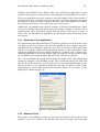
Automation Test Application .......................................................................................... 56
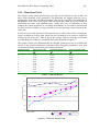
Database Tests ............................................................................................................... 56
Client Speed Tests........................................................................................................... 58
Encryption Speed Tests................................................................................................... 59
Encryption Strength Tests............................................................................................... 60
CONCLUSIONS ...................................................................................................................... 61
CONCLUSIONS ......................................................................................................................... 62
6.1
EVALUATION OF ACHIEVEMENT .......................................................................................... 62
6.2
SUGGESTIONS FOR FUTURE WORK ....................................................................................... 62
6.2.1
Client Application Modification ..................................................................................... 63
6.2.2
Encryption Speed............................................................................................................ 63
6.2.3
Encryption Strength........................................................................................................ 63
6.2.4
Further System Performance Tests................................................................................. 63
6.2.5
Network Traffic Tests ..................................................................................................... 64
REFERENCES ..................................................................................................................................... 65
7
APPENDIX 1: CLIENT DESIGN............................................................................................. 67
8
APPENDIX 2: SERVER DESIGN ............................................................................................ 68
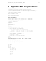
9
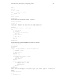
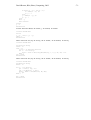
APPENDIX 3: RSA ENCRYPTION MODULE...................................................................... 69
10
APPENDIX 4: BINARY ENCRYPTION MODULE .............................................................. 72
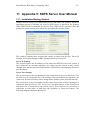
11
APPENDIX 5: SDFS SERVER USER MANUAL ................................................................... 74
12
APPENDIX 6: SDFS CLIENT USER MANUAL .................................................................... 77
13
APPENDIX 7: PROJECT GANTT CHART ........................................................................... 80
David Brown, BSc (Hons) Computing, 2002
-6-
Figures
Figure
Figure 1
Figure 2
Figure 3
Figure 4
Figure 5
Figure 6
Figure 7
Figure 8
Figure 9
Figure 10
Figure 11
Figure 12
Figure 13
Figure 14
Figure 15
Figure 16
Figure 17
Figure 18
Figure 19
Figure 20
Figure 21
Figure 22
Figure 23
Figure 24
Figure 25
Figure 26
Figure 27
Figure 28
Description
Client-Server Architecture
Napster Architecture
Gnutella Architecture
Encryption/Decryption process
The OSI Layered Model
WinSock Client-Server
Spiral Model
Evolutionary Development Model
Waterfall Model
Multiple Server System Model
Register User Protocol
Logon Protocol
Shared File List Protocol
Change Password Protocol
Change Keys Protocol
File Search Protocol
File Transfer Protocol
Change Keys Protocol
Database Tables and Replication
Client Application High Level View
Register User Details Form
Main Client Form
File Search Results
Server Application High Level View
Automated Test Program
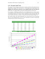
Graph of Access XP and MySQL Times
Graph of Client Test Results
Graph of Encryption Speed Tests
Page
10
11
11
12
14
17
21
21
22
24
28
28
29
29
30
31
31
31
33
36
37
37
43
46
56
57
58
59
Tables
Table
Table 1
Table 2
Table 3
Table 4
Table 5
Description
Access XP and MySQL Test Results
Client Test Results
Encryption Speed Test Results
Key Permutations
Decryption Times
Page
57
58
59
60
61
Acknowledgements
I would like to thank Dr William Buchanan for his help and guidance throughout the
project. I would also like to thank my fiancée Claire for her patience and support.
David Brown, BSc (Hons) Computing, 2002
1
Introduction
1.1
Scope and aims of the project
-7-
The main aim of this project was to create a system that allows files to be distributed
over a wide area and to be shared in a secure manner. The system should allow clients
to search for other clients that have required files and provide them with a mechanism
to share those files securely. It involves research in the following subjects:
• Distributed File System Architectures.
• Security Techniques.
• File Transfer Protocols.
• Network Programming Methods.
• Database Technologies.
This research will be applied in the creation of a final working system, which will be
tested and evaluated.
1.2
Background
Most applications on the Internet currently use a client-server model, where a client
actively connects to a server, which then provides it with a given resource. This
resource could be access to files, print services, and so on. A client-to-client (or peerto-peer) model provides an enhancement to this in that it allows clients to actively
seek other clients, without using a server as an intermediate device. There are though
many issues involved in this, especially related to the amount of network traffic
generated by peer-to-peer communications, and security. This project will try and
analyse a model for peer-to-peer communications for file sharing, and look at models
for enhancing the security of such as system.
Distributed, peer-to-peer, file sharing is one of the fastest growing and controversial
applications of the Internet. In its most basic form, file sharing can occur between two
computers connected via the Internet or another form of network connection. Napster
was one of the first applications to use peer-to-peer communications, and Oram
(2001) stated that:
... The first application that gave the Internet community the ability to share
files freely was Napster, which consisted of a centralised directory server
that stored shared file and addressability information of connected clients.
After Napster, a large number of file sharing applications became widely available.
Forte (2001) observed that there was a rapid appearance of these new applications and
stated that the majority of them were based on the peer-to-peer model. Waters (2001)
then showed that the use of this model in file sharing applications is increasing
rapidly, which is mainly due to the general availability of the Internet. Many
David Brown, BSc (Hons) Computing, 2002
-8-
researchers believe that peer-to-peer applications have a great potential, one such
researcher is Doherty (2002), who states ‘peer-to-peer shows great promise for file
sharing and collaboration’.
Peer-to-peer uses a different approach from Napster to sharing files. Gerwig (2002)
and Vrana (2001) define this approach as a decentralised network where client
computers communicate with each other directly, without the help of centralised
servers. So rather than using a central server to store file and client information, each
client uses an application that connects directly to other clients. According to Gerwig
(2002), out of the available peer-to-peer technologies, the most popular is Gnutella.
1.2.1 Napster
Oram (2001) and Kant, Iyler and Tewair (2002) describe the architecture of Napster
as a mixture of centralisation and decentralisation, consisting of centralised directory
servers that built and maintained a file list, adding and removing entries as individual
clients connected and disconnected. Yang and Garcia-Molina (2001) brand Napster as
a ‘hybrid’ peer-to-peer system, with their research concentrating on the issues and
trade-offs in the design of a scalable peer-to-peer system.
Oram (2001) also provided information on the popularity of Napster (before it was
closed, of course), where the directory servers kept track of thousands of clients,
holding millions of files, which amounted to over several terabytes of data1.
Napster gave Internet users a new and exciting way of sharing files; previously users
would have to upload their files onto a central web server in order for them to become
accessible to everyone. An overview of Napster’s architecture is defined in the
research papers written by Kant, et al. (2002) and Ratnasamy, et al. (2001). From the
papers it was discovered that Napster dispensed with the task of uploading, leaving
the files on the client’s PCs, simply brokering file requests from one PC to another, so
only the file addressability information would have to be stored on the central Napster
servers, not the file itself.
1.2.2 Gnutella
Aberer and Hauswirth (2001) state that Gnutella was the first fully decentralised peerto-peer system running on the Internet. Rather than using a central server that clients
use to find files, each client runs an application that connects directly to other clients.
File search requests are then passed from client-to-client until one acknowledges that
it has the requested file. A connected client in the Gnutella network is both a client
and an ad-hoc server, as they both get and/or send files.
A horizon in Gnutella defines the boundary up to which a client can see other client.
Horizons are defined to reduce the network communications to within a range of
clients. When a client connects to the network there can be any number of other
clients connected at the same time, but the client can only see clients within a given
domain. The horizon is defined using the Time-to-live (TTL) field in an IP datagram,
which defines the approximate distance that a packet can travel before it is discarded.
Oram (2001), states that the Gnutella horizon is set to seven decrements, which
effectively sets the maximum number of clients in a horizon to 10,000.
1
A terabyte is 1,024 GB’s, which is 1,099,511,627,776 Bytes.
David Brown, BSc (Hons) Computing, 2002
-9-
As Gnutella uses a horizon, each connected client sees a limited distance that radiates
out from the client. As each client is situated differently in the network, every client
will therefore see a different network. When clients connect and disconnect over time,
the network viewpoint changes and the connected clients see different clients as the
network changes around them.
Lv, et al. (2002) view the Gnutella architecture as the most attractive method for
sharing files, as there is no requirement for centralised storage and no need to control
the topology of the network, in relation to where the files are located.
The main issues involved in peer-to-peer communications are:
•
Bandwidth usage. As the network traffic is likely to increase as the network size
increases.
•
Security. As resources can be freely shared over a network, and there is no form
of authentication, thus it is not possible to refine security privileges.
•
Scalability. As there are limitations on the viewpoint that nodes have over the
network. Gnutella suffers in this area, as it does not scale well, as the network
traffic increases exponentially with the number of connected clients.
This report will focus on design issues for both security and scalability. Network
bandwidth will be discussed, but it is not an aim of this report to analyse this factor.
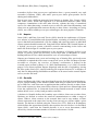
The report splits into seven main sections, these are:
•
Introduction. This chapter, and outlines the basic aims of the project, and its
context.
•
Theory. This chapter outlines the theory related to the technical background of
the project, such as Window’s sockets, the principles of encryption, file sharing
architecture, and so on.
•
Requirements Analysis. This chapter defines the high-level abstraction of the
system, and it basic functionality and the main system properties.
•
Design. This chapter outlines the full design process to match the requirements
analysis.
•
Implementation. This chapter outlines the main highlights for the coding. These
identify the key elements of the overall system, such as registering a user, and
encrypting a file.
•
Testing. This analyses the key functional tests for the system, such as encryption
speed, encryption strength, database comparisons, and so on.
•
Conclusions. This defines whether the main aims have been met, and how they
have been met. It also discusses future work.
David Brown, BSc (Hons) Computing, 2002
2
Theory
2.1
Introduction
- 10 -
Before the design of a secure file sharing application begins, there are five main areas
to be considered:
1. Distributed File System Architectures. It is important to consider the available
system structures to discover which is the most suitable.
2. Security. Cryptography is a technique used to maintain consistency and secrecy
of data, which has many different methods that deserve consideration.
3. File Transfer Protocols. The application requires the transfer of data between
two devices, so the format of the data transfer must be researched.
4. Network Programming. As the application will communicate over a network,
available network programming techniques must be considered, along with
techniques for improving performance.
5. Database Technologies. The application will require storage to a database, so the
available database technologies must be researched, to discover the most suitable.
Technologies for communicating with a database are also considered.
2.2
Distributed File System Architectures
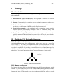
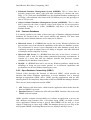
2.2.1 Client-Server Architecture
A distributed file system allows a file structure to be stored over one or more file
servers. Kantet, et. al. (2002) revealed that the client-server architecture is the most
widely used for this purpose. Figure 1 illustrates this model, which is based on a central
server that is responsible for providing a remote file service to clients. On receipt of a
valid client request, the server executes the appropriate operation and sends a reply back
to the client. This type of interaction is known as request/response or interrogation.
Server
(1) Request
(2) Response
(1)
(2)
Client
Client
Client
Figure 1 – Client-Server Architecture
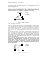
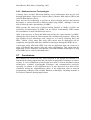
2.2.2 Napster Architecture
The Napster web page (2002) provided information on the Napster architecture, which
is based on a central directory server that contains addressability information on the
connected clients and information on the files they are sharing. This architecture is
illustrated in Figure 2. The central server offers connected clients the facility to search
David Brown, BSc (Hons) Computing, 2002
- 11 -
for a required file and assists in the identification of the most suitable location from
which to download that file.
Kant, et. al. (2002) stated that the centralisation of the directory server allows file
searches to be performed relatively fast, with the IP address of clients that host the
required file passed to the requesting client. The file download can then take place
between the requesting client and the client who hosts the file via TCP/IP.
(1)
(2)
(3)
(4)
Directory Server
Search
Locations
Request
Response
(1)
(2)
Client
(3)
(4)
Client
Client
Figure 2 – Napster Architecture
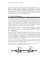
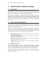
2.2.3 Gnutella Architecture
Kant, et. al. (2002) provide information on the Gnutella architecture, which is based on
a fully distributed approach where clients connect to each other directly through a
software interface that forms a high-level network. This architecture is illustrated in
Figure 3. When a client connects to the Gnutella network, all the sharable files are
made public to all other clients through a set of local folders that the client specifies as
shared.
The Gnutella client software, which is freely available from the Gnutella home page
(2002), is essentially a file serving system and search engine in one. Portmann, et. al.
(2001) provide function information on the underlying Gnutella protocol. They
outline that the discovery of peers and searching for files are the main elements of this
protocol, and are both implemented by sending messages to all connected clients
within the network horizon.
When a connected client submits a search to the Gnutella Network, the search
parameters are flooded throughout the network horizon, which returns any search
matches. The file download takes place between the requesting client and the client
who hosts the file. Technical information on this transfer was obtained from the
Gnutella development WWW page (2001), which revealed that the transfer is based on
an HTTP-like connection.
(4)
(3)
P eer
(1)
(1)
(2)
(3)
(4)
Search
Location
Request
Response
(2)
(1)
P eer
(2)
P eer
Figure 3 – Gnutella Architecture
David Brown, BSc (Hons) Computing, 2002
- 12 -
Unfortunately, Gnutella has problems in terms of scalability and ineffective use of
bandwidth. Both of which are common problems with peer-to-peer architectures.
Krishna, et. al. (2002) and Ripeanu (2002) propose that the problems are caused by
the way the Gnutella peer-to-peer networks are formed. Krishna, et. al. (2002)
propose a solution to improve the overall performance of the Gnutella network, by
creating small clusters of peers with similar file sharing interests. These clusters
further distribute the system and should generally reduce network traffic, as fewer
broadcasts are likely to be required for the smaller clusters.
2.3
Security Techniques
Peer-to-peer communications obviously have weaknesses in authentication, as there is
no intermediate server which can authenticate the client to the other client. In order
for us to under the problems that may be causes and their solution we must analyse
key areas of security, especially in data encryption, which is the best way to secure
both the data, and any transactions. Tanenbaum (1996) states that whenever a
computer system is a potential target for a malicious or mischievous attack, security
measures must be incorporated into these systems to prevent such actions. This is
especially relevant for systems that contain classified, confidential or financial
information, where integrity and secrecy is of paramount importance.
Whenever information is transmitted across a network, it is vulnerable to tampering
and eavesdropping. Coulouris, et. al. (2001), state that cryptography is used to
maintain the integrity and secrecy of information when it is exposed to such attacks.
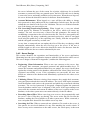
2.3.1 Cryptography
Singh (2001) provides a definition of cryptography, which is derived from the Greek
word kryptos, meaning ‘hidden’ and its aim is to hide the meaning of a message.
Encryption typically uses a standard well-published algorithm, and varies the
electronic cryptographic key. A cryptographic key is a mathematical parameter used
in an encryption algorithm so the encryption process cannot be reversed without the
key. As much as possible the encryption algorithm should be robust, so that it does
not have any weaknesses that can be exploited.
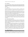
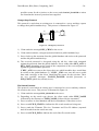
The process of encryption involves transforming plaintext into ciphertext, with the
reversal of this process called decryption. Figure 4 illustrates that both the encryption
and decryption is controlled by the cryptographic key.
There are two main types of encryption algorithm in use today. The first uses a secret
encryption key and the second uses public/private key pairs.
Cr yptographic
key
Encryption
Cryptographic
key
Ciphertext
Decryption
Figure 4 – Encryption/Decryption process
Plaintext
David Brown, BSc (Hons) Computing, 2002
- 13 -
2.3.2 Secret-key
In secret-key cryptosystems, a single key is used for both encryption and decryption.
The encryption key cannot be revealed to anyone other than the sender and recipient.
Buchanan (2000) states the two most popular secret-key techniques that are in use
today are DES (Data Encryption Standard) and IDEA (International Data Encryption
Algorithm).
2.3.3 Public-key
In public-key cryptosystems, each user has two related keys, a public-key and a
private key. The private key is only known by the user and is used to decrypt
messages encrypted by that user’s public-key, which is freely available to anyone.
Public and private keys are symmetrical, so code encrypted by one key can be
decrypted by the other. This means that knowing the public-key does not allow a user to
deduce the corresponding private key. Singh (2001) outlines that anyone can encrypt a
message with a user’s public-key and the only person that can decrypt it is the intended
recipient, as no one else has access to the required private key.
Buchanan (2000) describes how authentication can be performed with public-key
cryptosystems. This is achieved by encrypting a message with the sender’s private
key, effectively creating a digital signature of the message, which the recipient can
check by using the sender’s public-key to decrypt it. This proves that the sender was
the true originator of the message, and it has not been altered by a third party. The
most popular public-key technique is RSA, named after its creators Rivest, Shamir
and Adleman.
2.3.4 Pretty Good Privacy (PGP)
Both secret-key and public-key cryptosystems are used in secure distributed systems,
but both have disadvantages. In secret-key, both the sender and receiver must posses the
same key to encrypt and decrypt the data. Unfortunately, the key would have to be
passed from sender to recipient through a secret channel, but there is no guarantee the
channel is actually secure.
The main disadvantage of public-key cryptosystems is the encryption algorithms
require 100 to 1,000 times more processing power than their secret-key counterparts do.
This disadvantage is highlighted by Singh (2001). To overcome this Zimmermann
(1995) outlined a new technique, named PGP, which simplified the public-key
encryption process, and significantly reduced processing times. It operates by using a
random session key, which encipher the plaintext file conventionally. It thus combines
the RSA public-key cryptosystem with the speed of conventional encryption. This
session key is enciphered by the recipient’s public-key and sent along with the
enciphered text to the recipient. The recipient then uses their private key to decrypt the
session key, and uses the recovered session key to decipher the ciphertext message.
2.4
Network Protocols
An important factor in both peer-to-peer and client-server architecture is the protocol
used for the nodes to talk to each other. Typically, this is achieved using a layered
approach. At the lowest level, communication over a network involves the transfer of
bits from one machine to another. Mackenzie (1998) points out that to create an
David Brown, BSc (Hons) Computing, 2002
- 14 -
application to communicate in this manner would be an awkward task, as it would
take a large number of 0’s and 1’s to create a simple message. Instead, a high-level
interface for applications to communicate is provided by software running on the
networked computers, usually in the operating system itself.
All communicating entities on a network must agree on a set of rules and conventions
to be used when sending information over the network medium. These rules are called
a network protocol, which sets the format of messages and the appropriate actions
required for each message and specifies how the data is packaged into messages. The
network protocol can also determine the following:
•
Error checking to be used.
•
Data compression method.
•
How the sending device indicates a message is sent.
•
How the receiving device indicates a message is received.
2.4.1 Protocol Layered Model
Instead of having one large protocol to specify the rules for any possible form of
communication, the problem was divided into subsections, with a protocol required
for each subsection. To ensure that the protocols cooperate, they are developed in
complete sets called suites, where each protocol in the suite tackles one part of the
communication process. As a protocol is required for each subsection in a suite, it
increases the overall flexibility as new protocols can be created and used as required.
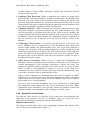
The most important factor in protocol design is the layered model, which describes
how the communication process can divide into subsections called layers. A protocol
suite is designed by specifying a protocol that corresponds to each layer. Comer
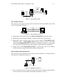
(1997) provides information on the most commonly used layered model, which is the
Open Systems Interconnection (OSI) developed by the International Standards
Organization (ISO) and is illustrated in Figure 5.
The OSI model provides a straightforward explanation of the associations between the
hardware and protocol components of the network. In the OSI model, the lowest layer
corresponds to the physical hardware and the following layers correspond to the
software. Stallings (2000) describes the purpose of each of the layers, which are as
follows:
Application
Application
Presentation
Presentation
Session
Session
Transport
Transport
Network
Network
Data Link
Data Link
Physical
Figure 5 – The OSI Layered Model
David Brown, BSc (Hons) Computing, 2002
- 15 -
1. Physical. Corresponds to the network hardware, such as the characteristics of the
voltage of transmitted signals, or the intensity of the light pulses.
2. Data Link. Specifies how transmitted data is received in a reliable way, and
involves adding extra bits for error detection, and so on. A typical example of this
layer is Ethernet IEEE 802.3.
3. Network. Determines how network addresses are specified and the routing of data
through interconnected networks. A typical example of this layer is IP (Internet
Protocol).
4. Transport. Specifies reliable transport details and the support of multiple streams
from a single computer. A typical example of this layer is TCP (Transport Control
Protocol).
5. Session. Specifies the establishment, maintenance and closing of a
communication. A typical example of this layer is HTTP (Hypertext Transfer
Protocol).
6. Presentation. Specifies how the data is represented, as systems may use different
data representation standards. A typical example of this layer is HTML (Hypertext
Markup Language).
7. Application. Provides network services to an application and specifies how the
application uses the network. A typical example of this layer is a WWW Browser.
When a protocol is designed using the OSI model, the protocol software is divided
into distinct modules which correspond directly to a layer. Layering also determines
how the modules interact, as each module communicates with the layer directly above
or below, so outgoing data will pass down through the layers and incoming data will
pass up through the layers.
The most widely known and used protocols are those relating to the Internet and TCP
and IP. Out of these protocols, the most relevant to this project is the File Transfer
Protocol (FTP).
2.4.2 File Transfer Protocol
FTP is one of the oldest Internet protocols, and is used to transfer files between two
computers on a TCP/IP network. FTP is based on the client/server architecture where
an FTP client is an application running on a computer that connects to a remote
computer running an FTP server application. When the connection between the client
and server is established, the client can then choose to send or receive files.
Tulloch (1996) provides information on FTP, which uses the Transmission Control
Protocol (TCP) to establish a connection-oriented session before initialising the data
transfer. TCP is used as it ensures reliable network communication, guaranteeing that
data will be delivered intact to the destination. The FTP server listens on TCP port
number 21 for connection attempts from an FTP client, this port is also used as for the
communication control port, allowing the client to send FTP commands to the server,
and to send the response from the server.
David Brown, BSc (Hons) Computing, 2002
2.5
- 16 -
Network Programming
Applications that communicate over a network use an interface to interact with the
communication protocols, which is typically known as an Application Programming
Interface (API). The API defines the operations that the application can call and the
number of arguments that the operation requires. For example, the API would contain
an operation used to establish a connection to a remote computer. Tulloch (1996)
states that out of the available APIs, the socket API is the de-facto standard.
2.5.1 Windows Sockets (WinSock)
WinSock provides connection-oriented, reliable two-way communication or
unreliable connectionless communication between applications on two computers.
WinSock is the Microsoft implementation of the Berkeley Sockets Application
Programming Interface (API), with the addition of Windows-specific extensions to
support the message-driven nature of the Windows operating system and is
implemented as a dynamic-link library (DLL). Examples of Windows applications
that are implemented using WinSock include Internet Explorer, Telnet and FTP.
2.5.2 Sockets
A socket is the logical endpoint between two communicating hosts on a network. Two
sockets form a bi-directional communications path between applications on two
different host computers. A socket is comprised of an IP address and a port number.
Some port numbers are reserved for well-known services (such as port 21 for FTP)
and others are for use by applications. Sockets can be configured to provide either a
connection-oriented reliable service or a connectionless, unreliable service.
Davis (1995) describes the function of the reliable service, which is based on TCP and
requires that a connection is established between the two processes before data can be
sent or received. The data is in a stream of bytes, which has no record delimiters in
the data stream, so if a process sends a 200-byte packet of data, the recipient process
may receive the data as a single 200-byte packet, or four packets of 50 bytes. If an
application were to depend on records of a fixed size being sent, the application must
be written to provide application-level headers in the data stream, as the packet size
will not be preserved on the receiving end.
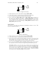
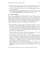
Dumas (1995) points out that the reliable service is suited to client-server
architectures. Typically, the server will create a socket, give the socket a name, and
wait for clients to connect to the socket. The client creates a socket and connects to
the server’s named socket. When the server detects the connection, it creates a new
socket and uses the new socket to communicate with the client. The server’s named
socket continues to listen for connections from other clients. This process is illustrated
in Figure 6.
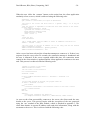
2.5.3 Microsoft WinSock Guidelines
WinSock was developed by Microsoft to enable Windows applications to take full
advantage of the available network bandwidth, allowing them to achieve outstanding
performance, reliability and throughput. This is illustrated by the following facts,
which were obtained from the Microsoft sockets development page (2002):
• Over 200,000 simultaneous TCP connections can be serviced by Windows.
David Brown, BSc (Hons) Computing, 2002
- 17 -
• A data transmission record of over 750 Mbps was set by Windows.
Windows serviced over 25,000 requests per second running Internet Information Server
in a test performed by SPECWeb96.
Server
Client
socket()
Create the Socket
socket()
Create the socket
bind()
Give the socket a name
listen()
Listen for connections
connect()
Connect to the server
accept()
Create a new socket while original socket
continues to wait for connections
send() / recv()
Send and Receive Data
send() / recv()
Send and Receive Data
closesocket()
Close the connection
closesocket()
Close the connection
Figure 6 – WinSock Client-Server
However, many applications are developed so they do not take advantage of the
performance capabilities of WinSock, as they unintentionally implement techniques
that hinder performance.
The most common mistake resulting in reduced application performance involves the
TCP/IP protocol, mainly the overhead required for establishing and terminating a
connection. For example, if an application uses the TCP/IP protocol on an Ethernet
network, it must send four 60-byte packets to establish a connection and the same
amount to terminate the connection. An application that regularly establishes and
terminates connections incurs this overhead on each occurrence.
Another common programming mistake involves the communication stream between
the applications. The most efficient way is to use a small number of large transactions
rather than a large number of small transactions, as large transactions are more
efficiently streamed. This may involve grouping smaller transactions together and
sending as one large transaction.
It also important to consider application behaviour when developing networked
applications, as some behaviours will work well on a local machine, but can cause
performance problems if run over a network. One such behaviour to avoid is a
‘chatty’ application, which involves the application sending a large number of small
transactions over the network. This is not an efficient method, as there is a large
network overhead for each transaction, in the same way as establishing a connection.
2.6
Database Technologies
A database is essentially a repository of data, which allows information to be stored
and retrieved quickly. Databases come in two main types:
David Brown, BSc (Hons) Computing, 2002
- 18 -
• Relational Database Management System (RDBMS). This is where data is
logically grouped into tables, with each table consisting of columns and rows.
Begg, et. al. (1998) state that RDBMS’s are the dominant database technologies in
use today, with estimated sales between $8-$10 billion per year, and growing at a
rate of 25% per year.
• Object Oriented Database Management System (OODBMS). This is where
data is stored in the form of objects, where each object has its own properties.
According to Begg, et. al. (1998), OODBMS’s only have a 3% share in the
database market.
2.6.1 Common Databases
It is entirely possible to use either of these two types of database, although relational
databases are favoured due to their speed, stability and maturity. The three most
commonly used relational databases in use today are as follows:
• Microsoft Access. Is a RDBMS that can be run on any Windows platform, but
does not have any of the advanced capabilities of the other two database systems.
The performance of Access is poor compared to the other database system, but is
commonly accepted in industry due to its ability to integrate with other Microsoft
technologies and its simplicity to set up.
• Microsoft SQL Server. Is a RDBMS that runs only on the Server versions of
Windows and is used for high-volume transaction-processing environments. It
consists of a server that runs the database software that processes requests
submitted by the database client software.
• MySQL. Is a RDBMS that can be run on any Windows platform, which has the
advantage of being an open source product, so its advanced capabilities and
performance can be used without incurring any costs.
2.6.2 Open Database Connectivity (ODBC)
Tulloch (1996) describes the function of Microsoft ODBC, which provides an
interface that allows Windows applications to access databases over a network
through an appropriate ODBC driver. ODBC provides applications with an API,
allowing them to be completely independent of the host DBMS that manages the data.
There are two main components used in ODBC:
1. API. Function calls that can be called from the application which define how the
data in a DBMS is accessed.
2. Database Drivers. Translates the API calls into ODBC function calls so the exact
DBMS used can respond.
ODBC provides complete interoperability as it allows an application to access any
SQL database using common code. A developer using ODBC can build a clientserver application without having to specify what DBMS will be used, as it can
simply be linked up at a later stage. ODBC has database drivers for over fifty of the
most popular DBMS’s including Microsoft Access, MySQL and SQL Server.
David Brown, BSc (Hons) Computing, 2002
- 19 -
2.6.3 Database Access Technologies
Currently, there are three Microsoft database access technologies that may be used
through applications: Data Access Objects (DAO), Remote Data Objects (RDO) and
ActiveX Data Objects (ADO).
DAO was the first technology to provide an object-oriented interface that allowed
developers to connect directly to database tables using ODBC, although it was not
able to utilise the entire functionality of ODBC.
RDO provides the same style of object-oriented interface to ODBC as DAO, but
practically all functionality of ODBC can be utilised. Unfortunately, RDO cannot
access databases created with Microsoft Access.
ADO is the successor to DAO and RDO and provides the same interface to ODBC,
although the object model in ADO contains more methods and properties. ADO is the
only database access technology with a future as it is slowly replacing DAO and
RDO. Tulloch (1996) states that using ADO means that an application will be
completely interoperable with other database technologies through an ODBC driver.
A developer using ADO and ODBC can write an application that can connect to a
range of different data sources using the same programming. This means that the
application will be completely interoperable with other database technologies as long
as an ODBC driver exists for that data source.
2.7
Conclusions
This chapter has covered the key areas involved in the design and creation of a
distributed file sharing application that will utilise cryptographic techniques to enforce
security. It covered important system design areas such as current distributed system
architectures, available cryptographic techniques and communication protocols,
especially in relation to the application-level. It also discussed areas that will be
considered during the implementation phase of the application such as network
programming techniques and available database technologies, including methods to
access these databases through applications.
David Brown, BSc (Hons) Computing, 2002
3
Requirements Analysis & Design
3.1
Introduction
- 20 -
The planning and design stage of any software project can be a difficult process. This
chapter highlights the actual specification of the proposed application, what are its
goals, how it will function to achieve these goals and what improvements the
application could bring to current existing file sharing technologies.
This chapter also highlights the available software process models. According to
Sommerville (2001), “A software process is a set of activities and associated results
that lead to the production of a software product”. Each of the software process
models illustrates a different approach to developing a software product. Each model
will be reviewed and the most appropriate method will be used to plan and develop
the project.
3.2
Software Engineering Methods
In any serious software project, a software process model is used. This allows the
management of all aspects involved in the production of the software, from the first
stage of specifying the proposed system through to final stage of maintaining the
system when it is complete and in use.
Three of most commonly used software process models illustrated by Sommerville
(2001) will be evaluated, with the most appropriate model selected for this project.
The three models are Spiral development, Evolutionary development and Waterfall.
Although these are different process models, each has common stages:
1.
Specification. Defines the functionality and operation of the software, set by
customers and potential users.
2.
Design and Implementation. The software is developed so it functions as
defined in the initial specification.
3.
Evaluation. The finished software is evaluated so it meets the functionality
and operation defined in the specification.
4.
Evolution. The software must be able to evolve to meet changes in technology
and user requirements.
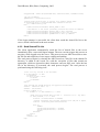
3.2.1 Spiral Development
The spiral model is shown in Figure 7 and represents the software development
process as a spiral, instead of a sequence of activities. The spiral starts at the centre,
with each loop representing a phase of the development. In each phase of the spiral,
objectives are identified, followed by risk analysis, development and evaluation.
The main advantage of the spiral model is there are no fixed phases such as
specification or design, which allows the software to be adapted according to
additional requirements.
David Brown, BSc (Hons) Computing, 2002
- 21 -
Risk
Analysis
Review
Prototyping
Requirements and
Development planning
Development and
Verification
Figure 7 – Spiral Model
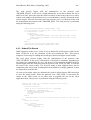
3.2.2 Evolutionary Development
This model involves creating an initial version of the software and then allowing the
target user to change the specification, advancing the software through multiple
versions until the final version is developed. In this model the specification,
development and validation stages are conducted concurrently. This model is
illustrated in Figure 8.
The advantage of this model is that the software can be produced in incremental
stages, with each stage having a revised specification from the target user. However,
this model suffers from two main disadvantages:
• The produced software systems are often structured poorly. This is a result of the
continual changes to the software, whose structure is often corrupted.
• The software development process is not visible. As the software is developed
quickly, documentation for each version is not produced and the target users
receive no deliverables to measure the development process.
Initial
Specification
i
Outline
Description
Development
Intermediate
i
Validation
Final
i
Figure 8 – Evolutionary Development Model
David Brown, BSc (Hons) Computing, 2002
- 22 -
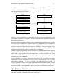
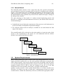
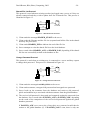
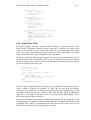
3.2.3 Waterfall Model
The Waterfall model consists of five stages that map onto specific development
activities that flow from one to another when an activity is completed and is shown in
Figure 9. The model can evolve if additional requirements are discovered at a later
stage in the project, which may involve repeating earlier stages. For example, during
the implementation stage problems may be discovered which will require a change to
the design of the software.
The main advantage of this model is it reflects normal engineering practice and
therefore, is commonly used and understood. However, this model suffers from two
main disadvantages:
• It should only be used when the requirements of the project are well understood, as
it does not readily accommodate requirements changes.
• The software product will not usually be available for use until almost the final
stages of the project.
The waterfall model will be selected over the other models as it suits the needs of this
project, as the requirements of the project are well understood and the software
product is not required until the later stages.
Requirements
Definition
System and
Software Design
Implementation
and unit testing
Integration and
system testing
Operation and
maintenance
Figure 9 – Waterfall Model
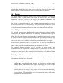
3.3
System Requirements
Many existing technologies allow clients to share files amongst themselves. The main
improvement this system offers over the other available technologies is that the files
will be shared securely. The security aspects will involve encryption of the file before
it is sent and subsequent decryption by the recipient of the file. This means only the
intended recipient will be able to read the contents of the file, so if the data
transmission were intercepted by a third party, it would be undecipherable.
Another security measure of the system should allow it to detect invalid users.
Therefore, if a hacker were able to break into a communication stream, the system
would be able to validate the authenticity of the user and then take appropriate action.
David Brown, BSc (Hons) Computing, 2002
- 23 -
The system must also provide users with a file search facility, or they would be unable
to share them. This facility should allow users to search for files via a file name or the
name of the user, which will return the entire list of files shared by that user.
3.4
Design
The original thinking behind this system was it could be deployed in a commercial
environment, where a group of users who require the need to share files amongst
themselves in a secure manner could subscribe to the service, and guarantee their
authenticity. Therefore, if it were to be deployed in a business environment, only
authorised users would be able to gain access share files with each other.
File sharing can already be achieved with a standard network operating system, as
access permissions can be set to directories, giving access only to authorised users.
However, this is not the safest or most efficient method of sharing files as passwords
can be obtained and transmitting files over a wide area using a network can be slow.
3.4.1 File System Architecture
The research conducted into distributed file system architectures outlined that the
Client-Server and Gnutella architectures are completely unsuitable for this type of
application, as both architectures do not meet the system requirements.
In the Client-Server architecture, files would have to be placed on the central server by
the clients in order to be shared. This does not meet the system requirements, as only
the client should host the file and should only release it when they want to. If the file
was to reside on a server, it could be viewed by any user with enough access rights.
In the Gnutella architecture, there is no central server to store user information as
clients connect directly to one another. This does not meet the system requirements
either, as there would be no method to validate the authenticity of a client.
The remaining Napster architecture will be used for the system model. This
architecture meets the requirements of the system, as the central server can store user
information to validate client authenticity. In addition, files are shared between the
clients, as the central server offers connected clients the facility to search for a file and
provides the address of the client hosting that file.
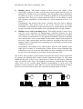
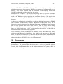
3.4.2 System Model
The Napster architecture was used as a basis for system design, out of which, three
system model candidates were developed:
1)
Single Server. This model consists of one server and when a client successfully
connects, their session details and files they are sharing are recorded in the
database. When connected, the client is free to interrogate the server for any
required files, with the connection details of clients that hold those files returned.
Unfortunately, this model suffers from a serious problem, as there is a central
point of failure for the system. So if the central server was to become unavailable,
so would the entire system. This could be the result of a hacker launching a denial
of service attack. This bombards the server with requests that slows it down to the
point where no one can gain access.
David Brown, BSc (Hons) Computing, 2002
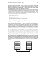
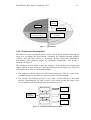
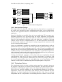
2)
- 24 -
Multiple Server. This model consists of three servers and when a client
successfully connects to either of them, their session details and files they are
sharing are recorded in the server database. This information is then replicated to
the other two servers, so each server maintains a global list of connected clients
and shared files. This gives a client connected to Server one the ability to search
and commence download of a file hosted by a client connected to Server 2 or
Server 3.
Unfortunately, this model suffers from a problem that may lead to database
inconsistencies. This would occur if one of the servers were to become
unavailable, as the databases in the functional servers would indicate that clients
are still connected to the unavailable server and that their files are still available.
3)
Multiple Server with Controlling Server. This model consists of four servers,
with one used exclusively for administering replication between the three
remaining servers. This solves the database inconsistency problem in the multiple
server model, as functional servers are updated immediately when the controlling
server detects that a server is unavailable. In this model, when a client connects to
any server, their session details and files shared are recorded in the local server
database, which is replicated to the controlling server and finally replicated to the
remaining two servers.
Unfortunately, the multiple server model suffers from the same problem as the
single server, as there is a central point of failure for the system, although if the
controlling server was to become unavailable, the three remaining servers would
be able to provide a partial service to their locally connected clients.
Out of these three possible system models, the model that will be used to implement
the system is the Multiple Server model, which is illustrated in Figure 10. The reason
behind this decision is there is no central point of failure for the system, which the
other two models suffer from. The database inconsistency problem that this model
suffers from can be resolved using WinSock programming, as each server will
maintain a socket connection to the other two servers, and will immediately be able to
detect if a server disconnects, due to the connection-oriented nature of sockets.
Figure 10 – Multiple Server System Model
David Brown, BSc (Hons) Computing, 2002
- 25 -
3.4.3 System Security
The Theory chapter of this report outlined the three main cryptographic techniques
used for the encryption of files. This section discusses the suitability of these three
techniques in context of the system.
In secret-key cryptography, the sender and receiver must have the same key to encrypt
and decrypt the file. This cryptographic technique is not suitable for the system as the
key would have to be sent from sender to recipient with every file transfer, or every
system user would have to have the same key. In either case, the security of the key is
not guaranteed.
In public-key cryptography, each user has two related keys, a public-key and a private
key. The private key is only known by owner of the key and is used to decrypt
messages encrypted by the corresponding public-key, which is available to anyone.
This cryptographic technique is not suitable for the system either, as public-key
encryption algorithms are up to 1000 times slower than secret-key encryption
algorithms.
The remaining cryptographic technique, Pretty Good Privacy (PGP) combines both
private and public-key cryptography, by using a random session key to encrypt the file
conventionally and then encrypting the session key with the recipient’s public-key. This
cryptographic technique will be used in the system, as it meets the security aspects set
in the system requirements.
Additionally, the use of PGP allows the server to detect invalid users, as authentication
can be achieved with public-key cryptography. The server can test the validity of a
connected user at any time by enciphering a small plaintext message using their publickey. The ciphertext is then sent to the user, where they will use their private key to
recover the plaintext and send it back to the server for validation. If the received value
does not match the original value, then the user is disconnected from the server.
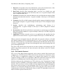
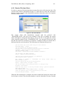
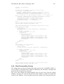
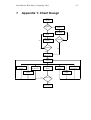
3.4.4 Client Design
This section identifies the operations and functionality of the client application,
illustrating how the client application interacts with the user and the server
application. The Client design is illustrated in Appendix 1.
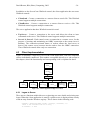
• Register User Details. When the client application is run for the first time, it will
check if the user has previously registered, possibly using the windows registry. If
no previous user details have been detected, the application will prompt the user to
register their details (username, password, public-key and modulus key).
Once the details are entered, the application randomly selects one of the servers,
connects and informs the server that a new user is registering their details. It then
sends the user details to the server. The Server then validates these details and
informs the user if they have been accepted or rejected, if they are rejected, the
server informs the user of the reason for rejection. The user may be rejected if the
username or the public/modulus keys are already in use, in either case, the user can
choose a new username or regenerate the public/private key combination.
• Logging In/Out. When a registered user attempts to login, the client application
selects one of the servers at random and connects. The server authenticates their
details, either granting or denying them system access. If they are denied access,
David Brown, BSc (Hons) Computing, 2002
- 26 -
the server informs the user of the reason for rejection, which may be an invalid
username or password. If they are granted access, the list of files the user is sharing
is sent to the server and made available to all system users. When the user logs out,
the server deletes the shared file entries for that user from the database.
• Account Maintenance. When logged on, a user will have the ability to change
their password or their public/private key combination. In both cases, the user will
submit the new details to the server for validation. The server will then inform the
user if the change was successful or not.
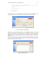
• File Searching/Transferring/Updating. When logged on, a user can submit
search queries by filename or username to the server, which will return any
matches. The user can select any of these files and commence file transfer by
establishing a connection to the user who hosts the file. The file is encrypted by the
user hosting the file using a randomly generated session key, which is encrypted
itself using the public-key of the requesting user. Finally, both the encrypted file
and the encrypted session key are then sent.
At any time, a connected user can update their list of files they are sharing, which
happens automatically when the user first logs on to the server. If the user is
already logged on, the server deletes the shared file entries for that user from the
database and writes the new entries submitted by the user.
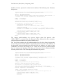
3.4.5 Server Design
This section identifies the operations and functionality of the server application,
illustrating how the server application interacts with the client and the other servers.
The server design is illustrated in Appendix 2, and has the following parts:
• Registering Client Information. When a new user connects to the server, they
will supply their username, encrypted password and public/modulus keys. To
ensure the username and public/modulus keys are unique, the server checks them
against the existing entries in the database, and notifies the client if they have been
registered successfully or not. If the registration was successful, the new user
details are written to the database and immediately replicated to the other server
databases.
• Validating Clients. When an existing client connects, they supply their username,
encrypted password and their current IP address. The server looks up the username
from the database and retrieves the password and public-key associated with that
username. The received password is decrypted, compared against the password
from the database and the user is informed of the result. If the logon attempt was
successful, the username and current IP address of the user is written to the server
database, so the other system users can connect directly via the IP address.
• Recording Shared Files. When a user logs on to a server, they automatically send
the server a list of files they are sharing. The server writes this file list into the
database, making the files available to all other system users. While connected, a
user can update their shared file list with the server any time.
• Searching for Files. When a connected user submits a file search to the server, it
first queries its own local database for any files matching the search criteria. If
there are any active connections to the other servers, the search query is then sent
David Brown, BSc (Hons) Computing, 2002
- 27 -
to their databases via the ODBC connection. Finally, any results from the file
search are sent to the user.
• Updating Client Passwords. When a connected user requests to change their
password, they send their username, encrypted old password and encrypted new
password. The server looks up the username from the database and retrieves the
password and public/modulus keys associated with that username. The received
old password is decrypted, compared against the password from the database and if
they match, the database is updated with the new password.
• Updating Client Keys. When a connected user requests to change their keys, they
send their username, encrypted password and new public/modulus keys. The
received password is decrypted using the old key values from the database and
compared against the password from the database. If they match, the server checks
the database for the new public/modulus key combination, in order to determine if
they are currently in use. If they are not in use, the new keys are written to the
database.
• Challenging Client Sessions. In a process invisible process to the clients, the
server randomly selects a connected user from the database and obtains their
current socket number and public/modulus keys. The server then generates a
random value, encrypts it with the public/modulus keys of the selected client and
sends the encrypted value to the client. The client will decrypt the value using their
private key and send the decrypted value back to the server for comparison. If the
decrypted value received from the client does not match the original, the user is
disconnected from the system.
• Other Server Connections. When a server is started, the administrator can
attempt to connect to the other servers manually, or allow the server to attempt to
connect automatically. If the automatic connection is chosen, the server will
attempt to establish a socket connection to the other servers every five seconds.
When a socket is not attempting to connect to a server, it will listen for a
connection. This way if all servers in the system are set connect automatically, they
will all do so within a relatively small amount of time.
When a socket connection is established from one server to another, an ODBC
connection is also created. Now every file search submitted by clients connected to
either of these servers is queried first in the local database of the server, followed
by the other server’s remote database.
If a server were to become unavailable, the servers connected to it would detect
this using their socket connections. The servers would then close their ODBC
connections to the unavailable server and only submit file searches to their local
databases and the remote databases of the remaining connected servers.
3.4.6 System Protocols Design
Now that the client and server operations of the system have been identified, the
application level protocols can now be designed. Using the client and server
operations, the following system protocols have been identified:
Register User Protocol
This protocol is used when a new user is attempting to register their details with a
server. This process is illustrated in Figure 11.
David Brown, BSc (Hons) Computing, 2002
(1)
- 28 -
(3)
(2)
Global Db
(4)
Client
Figure 11 – Register User Protocol
1) Client connects to a server and sends the message NEW_USER.
2) Client sends username, encrypted password and public/modulus keys.
3) Server decrypts the password and validates the keys/username.
4) Server sends either NEW_USER_ACK or NEW_USER_NAK, depending on
the result of the validation of the details. If NEW_USER_NAK were sent, the
server would then send a message to the client, identifying the reason for the
rejection. There are two possible messages: USER_EXIST (username in use) or
PUB_EXIST (public-key in use).
Logon Protocol
This protocol is used when an existing user is attempting to logon to a server. This
process is illustrated in Figure 12.
(1)
(3)
(2)
Global Db
(4)
Client
Figure 12 – Logon Protocol
1) Client connects to a server and sends the message EXIST_USER.
2) Client sends username, encrypted password and current IP address.
3) Server looks up the username from the database and retrieves the password and
public/modulus keys associated with that username. The received password is
decrypted and compared against the password from the global database.
4) Server sends either LOGON_ACK or LOGON_NAK, depending on the result of
the comparison of the received password against the global database password.
If LOGON_ACK were sent to the client, they would then start to send their list of
shared files to the server using the Shared File List Protocol. If LOGON_NAK
were sent, the server would then send a message to the client, identifying the
reason for the rejection. There are two possible messages: LOGON_PASSWD
(invalid password) or LOGON_USER (Invalid username).
David Brown, BSc (Hons) Computing, 2002
- 29 -
Shared File List Protocol
This protocol is used when an existing user has just logged onto a server or if they are
already connected and they wish to update their list of shared files. This process is
illustrated in Figure 13.
(1)
(4)
(2)
Local Db
(3)
(5)
Client
Figure 13 – Shared File List Protocol
1) Client sends the message SHARED_START to the server.
2) Client sends the filename and the file size (repeated until all the files in the shared
directory are processed).
3) Client sends SHARED_END to indicate the end of the file list.
4) Server attempts to write the shared file list to the local database.
5) Server sends either SHARED_ACK or SHARED_NAK, depending if the shared
file list was successfully written to the database or not.
Change Password Protocol
This protocol is used when an existing user is connected to a server and they request
to change their password. This process is illustrated in Figure 14.
(3)
(1)
(2)
(5)
Global Db
(4)
Client
Figure 14 – Change Password Protocol
1) Client sends the message PASSWD_CHNG to the server.
2) Client sends username, encrypted old password and encrypted new password.
3) Server looks up the username from the database and retrieves old password,
public and modulus keys associated with that username from the global database.
4) The received old password is decrypted and compared against the password from
the database. Server sends either PASSWD_ACK or PASSWD_NAK, depending
on the result of the comparison of the received old password against the global
database password.
If PASSWD_ACK were sent to the client, their new password would then be
written to the global database (5). If PASSWD_NAK is sent, there is only one
David Brown, BSc (Hons) Computing, 2002
- 30 -
possible reason for the rejection, so the server sends LOGON_PASSWD to inform
the client that the incorrect password was supplied.
Change Keys Protocol
This protocol is used when an existing user is connected to a server and they request
to change their public/modulus keys. This process is illustrated in Figure 15.
(3)
(1)
(2)
Global Db
(4)
Client
Figure 15 – Change Keys Protocol
1) Client sends the message KEY_CHNG to the server.
2) Client sends username, encrypted password and new public/modulus keys.
3) Server looks up the username from the global database and retrieves the password
and the old public/modulus keys.
4) The received password is decrypted using the old key values and compared
against the password from the global database. Server sends either KEY_ACK or
KEY_NAK, depending on the result of the comparison of the received password
against the global database password.
If KEY_ACK were sent to the client, their new public/modulus keys would then
be written to the global database (5). If KEY _NAK were sent, the server would
then send a message to the client, identifying the reason for the rejection. There
are two possible messages: LOGON_PASSWD (invalid password) or
PUB_EXIST (public-key already in use).
File Search Protocol
This protocol is used when an existing user is connected to a server and they submit a
file search to the server. This process is illustrated in Figure 16.
1) Client sends the message FILE_SEARCH to the server.
2) Depending on the search type chosen, the client sends either FILE_NAME
(followed by the filename) or USER_NAME (followed by the username).
3) Server searches its local database and the local databases of the other servers.
4) Server sends FILE_START to indicate the file search results are being sent.
5) Server sends the Filename, File size, Username and User IP Address (repeated
until all results from the search are sent).
6) Server sends FILE_END to indicate the end of the file search results.
David Brown, BSc (Hons) Computing, 2002
- 31 Local Db
Client
(1)
(2)
(3)
(4)
(3)
(3)
(5)
(6)
Figure 16 – File Search Protocol
File Transfer Protocol
This protocol is used when a client wishes to download a file from another client. This
process is illustrated in Figure 17.
(1)
(2)
(3)
(4)
Target Client
Requesting Client
Figure 17 – File Transfer Protocol
1) Requesting client sends the message FILE_TRANSFER to the target client.
2) Requesting clients sends the filename, public/modulus keys and username.
3) Requesting client can then receive one of two responses: TRANSFER_ACK
(Filename exists), or TRANSFER_NAK (Filename does not exist). If the target
client sends TRANSFER_ACK, it generates a random session key, encrypts the
file with it and encrypts the session key with the requesting client’s public-key.
4) Target client sends TRANSFER_START to indicate the start of the transfer,
followed by the encrypted session key and the encrypted file.
Client Validity Challenge Protocol
This protocol is used when the server wishes to test the validity of a connected client.
This process is illustrated in Figure 18.
(1)
(2)
Local Db
(3)
(4)
Client
Figure 18 – Change Keys Protocol
1) Server randomly selects a connected client from the local database and reads their
current socket connection number and public/modulus key values.
David Brown, BSc (Hons) Computing, 2002
- 32 -
2) Server generates a random value, encrypts it using the public/modulus keys and
sends the message SESS_CHALL to the client followed by the encrypted value.
3) Client then decrypts the value and sends the message CHALL_REPLY followed
by the decrypted value.
4) Server compares the received decrypted value with the original value and sends
either SESS_ACK or SESS_NAK, depending on the result of the comparison. If
the server sends SESS_NAK, the client is disconnected from the server.
3.4.7 Database Design
There were two candidates for the database management system: relational or objectoriented. The relational database was selected for use, as they are fast, stable and
widely available. Additionally, the data that will be stored in the database is not
complex. MySQL was chosen for the database management system, the justification
of this decision can be found in the Technology Choices section later in this chapter.
From the identification of the server operations, it is clear that each server in the
system would require two databases: a local database and a global database.
• The global database will store the details of all registered system users, such as
username, password and public/modulus keys. When a user registers at a server,
their details are written to this database and immediately replicated to the other
server’s global database. This will maintain consistency throughout the system, as
a user may register with one server and attempt to logon to another server at a later
stage. If this were to happen without replication, the other server would have no
record of this user and deny them access.
The global database will contain one table called SystemUsers, which has the
following fields: Username, Password, PublicKey and ModulusKey.
• The local database will store details of the users currently logged on to the server
and the list of files they are sharing. When a user logs in, their socket number,
username and IP address are written to this database. This is followed by the names
and sizes of any files they are sharing. Instead of this information being replicated
to the other server’s databases, the servers in the system connect to each other’s
local databases via an ODBC connection to submit file search queries, which
removes a large replication overhead from the system.
The local database will have two tables: ConnectedUsers and SharedFiles. The
ConnectedUsers has the following fields: SocketNumber, Username and
IPAddress. The SharedFiles table has the following fields: Username, Filename
and Filesize.
The database tables and their replication associations are illustrated in Figure 19.
David Brown, BSc (Hons) Computing, 2002
Server 1
Local
ConnectedUsers
Db
SharedFiles
Global
Db
SystemUsers
Server 2
Local
- 33 -
ConnectedUsers
SharedFiles
Db
SystemUsers
Global
Db
ConnectedUsers
Db
SharedFiles
Global
Db
SystemUsers
Server 3
Local
Figure 19 – Database Tables and Replication
3.4.8 User Interface Design
The design of the User Interface (UI) began after the client and server operations of
the system were identified, as these operations describe how a user would interact
with the client application and how an administrator would interact with the server
application.
Instead of sketching out possible client and server application UI’s on paper, nonfunctional prototypes were developed using the Rapid Application Development
(RAD) capabilities of Visual Basic. This made the creation of the required amount of
forms for each application simplistic, with each form given a number of relevant
controls, such as list boxes, command buttons, etc. The RAD capabilities also allowed
the layout of the controls on each form to be easily arranged, so the controls are laid
out in a visually pleasing manner.
It was very important to consider the potential user for each application, in order to
determine the level of complexity. The client application could conceivably be used
by someone with very little computing experience, so the UI must be straightforward
and give the user access to the client functions easily. The server application however,
would be used by a system administrator, who would have a great deal of experience
with configuring systems and would require detailed information on the performance
of the server and access to complex configuration options.
Creating non-functional prototypes of the client and server applications allowed
experimentation with each UI in order to find the right balance of simplicity with
functionality for each application. Additionally, the creation of prototypes decreased
the overall implementation time for each application, as the functionality of the
controls on each form were added during the development phase of the project.
3.4.9 Technology Choices
The technologies used to develop a software project may have a negative impact on
the progress of the project, so must be selected carefully. The main decisions on the
technologies used during this project relate to the design and implementation stages.
There were two possible candidates for the programming language to develop the
applications, which were Visual Basic (VB) and Java. VB is considered the best
application for Rapid Application Development (RAD), while Java is platform
independent and has a large number of networking libraries available. VB6 was used
David Brown, BSc (Hons) Computing, 2002
- 34 -
instead of VB.NET, as VB.NET is radically different as it fully supports objects and
multithreading, but no longer supports WinSock as a means for communicating over a
network. These issues combined with the availability of the language meant that
VB.NET would not be a viable option for this project.
InstallShield for Windows is an independent package that was used to create the
installation program for both Client and Server applications. It allows entries to be
made to the Windows registry regarding the installation directory of the application
and allows required application DLLs to be registered in the Windows system
directory.
As the server application is designed for use with an additional two servers, a DBMS
with replication capabilities was required. Replication in Microsoft Access XP is
limited, as it requires the use of an additional application called Replication Manager
that can only replicate tables after a time interval, with the lowest interval being
fifteen minutes. Information on the replication capabilities of MySQL was obtained
from the MySQL web page (2002), which justified the selection of MySQL as
transaction-based replication is fully supported.
There were three possible technologies for database access: DAO, RDO and ADO,
which are both Microsoft technologies. Since ADO is the successor to DAO and
RDO, the other two technologies, it is the only one that has a future. Another benefit
of using ADO is the application will be completely interoperable with other database
technologies through an ODBC driver via SQL statements.
3.5
Conclusions
This chapter has covered the main decisions that were made during the analysis and
design phase of the project. These decisions, such as using the waterfall software
process model, using the multiple server architecture and using PGP for system
security, had a fundamental effect on the implementation of the system, which is
covered in the next chapter.
David Brown, BSc (Hons) Computing, 2002
4
Implementation
4.1
Introduction
- 35 -
This chapter highlights the implementation of the system corresponding to the design
specification outlined in the previous chapter, concentrating on the client and server
applications. A high-level view of these applications is adopted, which illustrates the
integration of the system protocols. This chapter also highlights a solution to the
problem when sending data using a socket connection.
4.2
WinSock Programming
In the theory chapter of this report, Davis (1995) highlighted that when data is sent
using sockets, it is sent in a stream of bytes, which has no record delimiters in the data
stream. This meant that if an application were to depend on records of a fixed size
being sent, the application must be written to provide application-level headers in the
data stream, as the packet size will not be preserved on the receiving end.
The main WinSock connection in the client application (ServerConn) is used to create
a connection to the server and allows the client to issue commands to the server. In
order to understand responses from the server, each received string is stripped down
into its component parts.
This is performed by obtaining the length of the received string, removing one
character from the string at a time and storing each character in a variable until a
control code is found. When one is found, any remaining characters in the string are
stored and the relevant procedure is executed using the variable holding the received
string. This process is shown in the following code example:
'Read incoming data into the str variable, strip the server command off it
'and strip the other pieces of data off the string
ServerConn.GetData recString
'get the length of the received string
stringLen = Len(recString)
For count = 1 To stringLen
'get the character
workstring = Mid(recString, count, 1)
'check to see if this is a returncode (signifies end of string)
If workstring = vbCr Then
'The server has a protocol command code so strip the code off
'the received string and execute the relevant procedure
recString = Right(recString, stringLen - count)
Select Case serverCommand
Case "NEW_USER_ACK" 'new user registration accepted
Case "NEW_USER_NAK" 'new user registration rejected
End Select
End If
'append this to the server command variable
serverCommand = serverCommand & workstring
Next Count
David Brown, BSc (Hons) Computing, 2002
- 36 -
In addition to the ServerConn WinSock control, the client application has two more
WinSock controls:
• ClientSend – Creates a connection to a remote client to send a file. This WinSock
control supports multiple connections.
• ClientRecieve - Creates a connection to a remote client to receive a file. This
WinSock control supports multiple connections.
The server application has three WinSock controls in total:
• TcpServer – Creates a connection to the server and allows the client to issue
commands to the server. This WinSock control supports multiple connections.
• Server1 & Server2– Each control creates a connection to a remote server, for the
purpose of creating and maintaining an ODBC connection to the remote server’s
database. The connection-oriented nature of sockets allows the local server to
detect if the remote server becomes inactive and to close the ODBC connection.
These WinSock controls allow only one connection.
4.3
Client Implementation
Figure 20 illustrates a high-level view of the client application, with each important
section individually numbered. This number corresponds directly to a sub-section in
this chapter, where the functionality and corresponding code is explained in detail.
Logon to
server
4.2.1
Send shared
file list
4.2.2
Connected
Submit file
search
4.2.3
Send file
to client
4.2.4
Receive file
from client
4.2.5
Authenticate
details
Change keys/
password
4.2.6
4.2.7
Change
Shared File
Dir 4.2.8
Figure 20 – Client Application High Level View
4.3.1 Logon to Server
There are two functions within this area: registering new user details and existing user
logon. When the client application is started, a splash screen is displayed that secretly
reads an entry from the Windows registry. This is shown in the following code:
userName = GetSetting("SFDS_Client", "Startup", "Username", "")
'check is the username value has an entry
If userName = "" Then
David Brown, BSc (Hons) Computing, 2002
- 37 -
strCont = MsgBox("SDFS Client has detected that you are not registered, do
you want to register now?", vbInformation + vbYesNo)
If strCont = vbNo Then
End
Else
frmRegister.Show
End If
Else
Unload frmRegister
frmMain.Show
End If
If the required entry is not found, then it is clear that the user is unregistered, so the
form shown in Figure 21 is displayed to prompt the user to enter their details.
Figure 21 – Register User Details Form
This form sets the shared file directory to the installation directory of the client
application and generates a public/private key set, which the user can regenerate if
required. These keys are generated using the ‘CreateKeys’ procedure of the RSA
module, which is modified from the code supplied by Griffths (2000) and attached in
Appendix 3.
Once successfully registered with the server, the form shown in Figure 22 is presented
to the user. This same form is displayed if the entry is found in the Windows registry
when the client application is started.
Figure 22 –Main Client Form
David Brown, BSc (Hons) Computing, 2002
- 38 -
When the user clicks the ‘connect’ button on the main form, the client application
randomly selects a server, which is achieved using the following code:
serverFile = FreeFile
Open (stName & "\Server.dat") For Input As #serverFile
'now read in the values and store them in a dynamic array - as it may be
possible
'that the service is expanded to include more than three servers in the future
Do Until EOF(1)
Line Input #serverFile, stLine
'preserve the contents in the array
ReDim Preserve dynArray(count)
dynArray(count) = stLine
count = count + 1
Loop
'close the file
Close #serverFile
'get a random number from the number of server IP addresses read from file
randVal = Int(Rnd * count)
'use that value to get the IP address out of the array and set the Winsock
control RemoteHost variable
frmMain.ServerConn.RemoteHost = dynArray(randVal)
frmMain.ServerConn.RemotePort = 1001
After a server has been selected, the client then attempts to connect to it. If there is no
response from the server after 20 seconds, the connection attempt is abandoned and
the user is informed. If the server responds within this time, the connection status
control in the client window is updated and the client application continues to the next
task. This process is achieved with the following code:
'attempt to connect to the server
frmMain.ServerConn.Connect
'set the status of the connection
Call connectionStatus
startTime = Timer
Do While frmMain.ServerConn.State <> 7 And Timer - startTime < 20
DoEvents
Loop
'if the Timer exceeds 20 Seconds, the program times out
If Timer - startTime > 20 Then
GoTo Timeout
Else
'connection established - set connection status so user sees a result
Call connectionStatus
End If
Exit Sub
Timeout:
'notify user connection has timed out
Call MsgBox("Connection timed out.", vbExclamation, "SDFS Client")
As soon as the client successfully connects to the server, the client sends the user
details to the server. This process begins with the encryption of the user password
using the ‘enc’ method of the RSA module, which is attached in appendix 3. The
client then obtains its current IP address and sends this information, along with the
username to the server. This is achieved with the following code:
David Brown, BSc (Hons) Computing, 2002
- 39 -
encryptPasswd = RSAv1.enc(txtPasswd.Text, txtPrivate.Text, txtModulus.Text)
'get the IP address
ipAddressVal = ServerConn.LocalIP
'inform server existing user is logging in by sending 'EXIST_USER'
If ServerConn.State <> sckConnected Then 'Connection failed
Call cmdDisconnect_Click
Else
frmMain.ServerConn.SendData "EXIST_USER" & vbCr
'send details to the server
frmMain.ServerConn.SendData
frmMain.ServerConn.SendData
frmMain.ServerConn.SendData
End If
(username, password and current IP address)
txtUser.Text & vbCr ‘username
encryptPasswd & vbCr 'enc password
ipAddressVal & vbCr 'ip address
If the logon attempt is successful, the client then sends the shared file list to the
server, which is discussed in the next section.
4.3.2 Send Shared File List
The client application automatically sends the list of shared files to the server
immediately after a successful logon attempt. The user can also trigger this process at
any time, while logged on to the server. This process uses an ADO record set to store
the file list and comprises of two stages: reading and sending.
The read process begins by clearing the ADO record set, each file in the shared file
directory is added to the record set, with the exception of files that contain an
apostrophe, which are ignored as these characters cause an SQL error. After the last
file in the directory is processed, the send process begins. The read process is
performed using the following code:
'first clear any records in the recordset
If rs.RecordCount > 0 Then
rs.MoveFirst
Do While rs.EOF = False
rs.Delete
rs.MoveNext
Loop
End If
'Loop through the shared directory and populate the Recordset
strPath = txtDirList.Text & "\"
strName = Dir(strPath)
Do While strName <> ""
If strName <> "." And strName <> ".." Then
'Make sure the filename does not have a ' character in it - SQL Error
If InStr(strName, "'") = 0 Then
FileSize = FileLen(strPath & strName)
'Convert filelength into the best possible value (Mb, Kb or bytes)
strFinal = modClient.getFileSize(FileSize)
With rs
.AddNew
.Fields.Item("Filename") = strName
.Fields.Item("Filesize") = strFinal
.Update
End With
End If
End If
strName = Dir
Loop
David Brown, BSc (Hons) Computing, 2002
- 40 -
The send process begins with the transmission of the protocol code
‘SHARED_START’ to the server, which informs the server that a shared file list is
about to be sent. Each entry from the ADO record set is then sent to the server, with a
control code added to the end that acts as a record delimiter, which is discussed earlier
in this chapter. After the last entry has been sent, the server is informed of this with
the transmission the protocol code ‘SHARED_END’. The send process is performed
using the following code:
frmMain.ServerConn.SendData "SHARED_START" & vbCr
'use the recordset to send the files - first check there are files in it
If rs.RecordCount > 0 Then
rs.MoveFirst
Do While rs.EOF = False
frmMain.ServerConn.SendData (rs.Fields.Item("Filename") & vbCr)
frmMain.ServerConn.SendData (rs.Fields.Item("Filesize") & vbCr)
rs.MoveNext
Loop
End If
'now that all files are sent, inform the server
frmMain.ServerConn.SendData "SHARED_END" & vbCr
4.3.3 Submit File Search
While logged on to the server, a user is free to submit file search queries either by the
name of the file or by the username of the user hosting the files. This process
comprises of two stages: sending the search query and receiving the search results.
The send query process begins with the transmission of the protocol code
‘FILE_SEARCH’ to the server, followed by a file name or username, depending on
the search type submitted by the user. The process of receiving the results from a file
search begins with the client receiving the protocol code ‘FILE_START’ to indicate
the start of the search results. The received string is then stripped down into its
component parts and a count is maintained on the number of strings gathered, as four
are required per search result.
As soon as four string values are obtained, the result is written into an ADO record set
to store the search results. When the protocol code ‘FILE_END’ is processed, the
entries in the ADO record set are then used to populate the list on the client
application form. This process is performed using the following code:
'check to see if this is a returncode (signifies end of string)
If workstring = vbCr Then
retCount = retCount + 1
'check if this is the end of the list - "FILE_END"
If searchString = "FILE_END" Then
'update the search file listview box
Call populateFileSearch
Exit Sub
End If
‘retcount used to count the strings received as there are four for each
result
Select Case retCount
Case 1 'filename
recFile = searchString
searchString = ""
workstring = ""
David Brown, BSc (Hons) Computing, 2002
- 41 -
Case 2 'filesize
recSize = searchString
searchString = ""
workstring = ""
Case 3 'Username
recUser = searchString
searchString = ""
workstring = ""
Case 4 'User ip address
recIP = searchString
searchString = ""
workstring = ""
'Add this received search into
With rs2
.AddNew
.Fields.Item("Filename") =
.Fields.Item("Filesize") =
.Fields.Item("Username") =
.Fields.Item("IP") = recIP
.Update
End With
the recordset
recFile
recSize
recUser
4.3.4 Send File to Client
This process begins with the requesting client sending a connection request to the
target client’s ClientSend WinSock control. When this is detected, the target client
creates a new instance of the socket and accepts the connection from the remote
client. The remote client then sends the protocol code ‘FILE_TRANSFER’, the name
of the required file, their public/modulus keys and username.
The target client then checks if the requested file exists in the shared file directory. If
not, the protocol code ‘TRANSFER_NAK’ is sent, to inform the requesting client that
the file no longer exists. If the file does exist, the target client then generates a random
32-bit key using the following code:
Dim keyVal As String
Dim randVal As Integer
Dim i As Integer
'Loop 32 times and generate a random 0 or 1
For i = 1 To 32
randVal = Rnd(1)
'Add the random number to the key string
keyVal = keyVal & randVal
Next i
getEncryptionKey = keyVal
The file is then encrypted with the session key using modified code supplied from Lai
(2002), which is attached in Appendix 4. Once the file has been successfully
encrypted, the session key is encrypted using the public and modulus keys of the
requesting client using the ‘enc’ method of the RSA module, which is attached in
Appendix 3. The target client then sends the protocol code ‘TRANSFER_ACK’,
followed by the encrypted session key.
The target client begins the process of sending the encrypted file by setting the size of
the data packet. This packet is filled with data from the encrypted file and sent to the
requesting client, which is repeated until the entire file has been sent. After the file
has been successfully sent, the encrypted file is deleted.
David Brown, BSc (Hons) Computing, 2002
- 42 -
During the send process, a count is kept on the amount of bytes sent which is used to
update the upload list on the client application form. The send process is performed
using the following code:
'Set the packetsize to send
packetsize = 256
'Used to make the sent file the same size as the original file
lastdata = False
Temp = ""
'Loop until End Of File.
Do Until EOF(OpenedFileNbr)
'If the last packet of data has been sent - exit the loop
If lastdata = True Then
Exit Do
End If
'Adjust the packetsize for the last packet, so too much data isn't sent
If FileLength - Loc(OpenedFileNbr) <= packetsize Then
packetsize = FileLength - Loc(OpenedFileNbr)
lastdata = True
End If
'Make the temp variable equal to the size of the packet
Temp = Space$(packetsize)
'Load the data into the empty Temp string
Get OpenedFileNbr, , Temp
If ClientSend(Index).State <> sckConnected Then
' The connection has failed so close the file, delete it and update the
' listview
Close OpenedFileNbr
Kill strEncFilePath
itemNumber = modClient.getUploadListItem(Index)
lvwUpload.ListItems(itemNumber).SubItems(4) = "Failed"
Unload ClientSend(Index)
Exit Sub
End If
'This is used to keep track of how much data is sent
doneBytes = doneBytes + Len(Temp)
'Get the best format for the amount of data sent
FileSize = modClient.getFileSize(doneBytes)
'Find the position in the listview of this upload item and update the
'amount sent
itemNumber = modClient.getUploadListItem(Index)
'Update the amount sent for this item - acts as a send progress for the
'user
lvwUpload.ListItems(itemNumber).SubItems(4) = FileSize
'Send the data to the remote client(if still connected)
If ClientSend(Index).State = sckConnected Then
ClientSend(Index).SendData (Temp)
Else
'The connection has failed so close the file, delete it and update the
' listview
Close OpenedFileNbr
Kill strEncFilePath
itemNumber = modClient.getUploadListItem(Index)
lvwUpload.ListItems(itemNumber).SubItems(4) = "Failed"
Exit Sub
End If
DoEvents
Loop
'Close the file now that the last packet has been sent
Close OpenedFileNbr
David Brown, BSc (Hons) Computing, 2002
- 43 -
4.3.5 Receive File from Client
In order to request a file download, the user must first select a file from the list of file
search results, which is illustrated in Figure 23. When the user clicks the ‘download’
button, an entry is made in the download list and the client then waits for a response
from the remote client.
Figure 23 –File Search Results
The remote client will immediately respond with the protocol code
‘TRANSFER_NAK’ if the file is not available. If the file is available, the remote
client will begin to encrypt the file and as soon as the file is encrypted, the remote
client sends the protocol code ‘TRANSFER_ACK’, the encrypted session key and
then the file itself. The session key is stored in a variable for later use and the file is
built-up from the received packets. The following code illustrates this process:
'put the session key in the global array for later retrieval
sessionKey(Index) = strSess
'Get the filename off the download listview
'Find the entry in the listview by using the function in modClient
itemNumber = modClient.getDownloadListItem(Index)
'Set the filename to this
strFileName = lvwDownload.ListItems(itemNumber).SubItems(1)
'Get the path of the SDFS Client App
strPath = modServer.getProgramLocation()
'Open the file for writing and give it an identifier
DownloadingFile(Index) = FreeFile
Open
strPath
&
"\Temp\"
#DownloadingFile(Index)
&
strFileName
For
Binary
Access
Write
As
'Trim the session key off the the received string
strData = Right(strData, stringLen - count)
'Get the new length of the string and store it in the byte array
stringLen = Len(strData)
'Reset the array value - as this may have been used by a previous connection
downloadBytes(Index) = 0
downloadBytes(Index) = downloadBytes(Index) + stringLen
'Write the remaining part of the received string to this file
Put #DownloadingFile(Index), , strData
When the file transmission is complete, the socket connection between the remote and
local clients is closed. The old socket number is used to obtain the file entry from the
David Brown, BSc (Hons) Computing, 2002
- 44 -
download list, and the size of the downloaded file is compared against the original
size of the file from the list. If both sizes are identical, the file was downloaded
successfully, so the session key is decrypted and used to decrypt the file. If the file
sizes do not match, then the downloaded file is deleted. The following code illustrates
this process:
'Find the entry in the listview by using the function in modClient
itemNumber = modClient.getDownloadListItem(Index)
'Set the filename to this
strFileName = lvwDownload.ListItems(itemNumber).SubItems(1)
'Now test to see if this download completed - if not exit
'If Download completed successfully, filesize and received filesize should be
'the same
If lvwDownload.ListItems(itemNumber).SubItems(2) <>
lvwDownload.ListItems(itemNumber).SubItems(4) Then
'Delete and reset the temporary file
Close DownloadingFile(Index)
DownloadingFile(Index) = 0
Kill strPath & "\Temp\" & strFileName
resumeError:
'Update the status of the download item in the ListView
'so the user can clear it at a later stage
itemNumber = modClient.getDownloadListItem(Index)
lvwDownload.ListItems(itemNumber).SubItems(4) = "Failed"
Exit Sub
End If
'The file was successfully downloaded so now close and reset the file
'that was written to by the winsock object
Close DownloadingFile(Index)
DownloadingFile(Index) = 0
'We now have the filepath and encrypted session key
'first recover the encrypted key
decryptSess = RSAv1.dec(sessionKey(Index), txtPrivate.Text, txtModulus.Text)
'Before decrypting the file - inform the user of this by updating
'the status in the listview (as decryption can take some time on big files)
lvwDownload.ListItems(itemNumber).SubItems(4) = "Decrypting"
'Now decrypt the received file using this information
Call modBinaryEncrypt.DecryptFile((strPath & "\Temp\" & strFileName), (strPath
& "\Shared\" & strFileName), decryptSess)
'Update the download listview for this item
lvwDownload.ListItems(itemNumber).SubItems(4) = "Completed"
'Delete the old File from the temp directory
Kill (strPath & "\Temp\" & strFileName)
4.3.6 Authenticate Details
This process begins when the protocol code ‘SESS_CHALL’ is received from the
server. The client decrypts the received value using the private and modulus keys and
sends the server the protocol code ‘CHALL_REPLY’, followed by the decrypted
value. This process is performed using the following code:
'We now have a received encrypted value from the SDFS Server
'unencrypt it using the private key
challVal = RSAv1.dec(challString, txtPrivate.Text, txtModulus.Text)
'Inform the server that the response is being sent
'and send the decrypted value to the server
ServerConn.SendData "CHALL_REPLY" & vbCr
David Brown, BSc (Hons) Computing, 2002
- 45 -
ServerConn.SendData challVal & vbCr
4.3.7 Change Password/Public-key
While logged on to the server, a user can change their password or their public/private
keys at any time. After selecting a new password, the client application encrypts it
along with the old password. The protocol code ‘PASSWD_CHNG’ is sent to the
server, followed by the username and the old & new passwords. This is achieved
using the following code:
'encrypt the old password with the users private key
encryptOldPasswd = RSAv1.enc(txtPasswd.Text, txtPrivate.Text, txtModulus.Text)
'encrypt the new password with the users private key
encryptNewPasswd = RSAv1.enc(txtPasswd.Text, txtPrivate.Text, txtModulus.Text)
'inform the server that a password change is being sent
'achieved by sending the code 'PASSWD_CHNG'
If ServerConn.State <> sckConnected Then 'Connection failed
ServerConn.Close
Else
ServerConn.SendData "PASSWD_CHNG" & vbCr
ServerConn.SendData txtUser.Text & vbCr 'contents of username text box
ServerConn.SendData encryptOldPasswd & vbCr 'encrypted old password
ServerConn.SendData encryptNewPasswd & vbCr 'encrypted new password
End If
A new public/private key set can be automatically generated if required by the user.
After a new key set is generated, the client application encrypts the user’s password
and informs the server that a key change is being sent, by sending the protocol code
‘KEY_CHNG’, followed by the username, password and new public/modulus keys.
This is achieved using the following code:
'encrypt the password with the users OLD private key
encryptPasswd = RSAv1.enc(txtPasswd.Text,txtPrivate.Text,txtModulus.Text)
'first inform the server that a key change is being sent
'achieved by sending the code 'KEY_CHNG'
If ServerConn.State <> sckConnected Then 'Connection failed
ServerConn.Close
Else
ServerConn.SendData "KEY_CHNG" & vbCr
ServerConn.SendData frmMain.txtUser.Text & vbCr 'contents of username text
box
ServerConn.SendData encryptPasswd & vbCr 'encrypted password
ServerConn.SendData txtPublic.Text & vbCr 'new public-key
ServerConn.SendData txtModulus.Text & vbCr 'new modulus key
End If
4.3.8 Change Shared File Directory
While logged on to the server, a user can change their shared file directory at any
time. After selecting a new directory, the client application checks if the new
directory is different from the previous one. If it is, the Windows registry is updated
and the new list of shared files is sent to the server.
4.4
Server Implementation
Figure 24 illustrates a high-level view of the server application, with each important
section individually numbered. This number corresponds directly to a sub-section in
this chapter, where the functionality and corresponding code is explained in detail.
David Brown, BSc (Hons) Computing, 2002
- 46 -
Initialise
Server
4.3.1
Active
Accept client
connection
4.3.2
Connect to
server
Challenge
client session
Perform file
search
4.3.4
4.3.5
4.3.3
Client Password
/Key change
4.3.6
Update client
file list
4.3.7
Figure 24 – Server Application High Level View
4.4.1 Initialise Server
When the server is started, it first creates connections to its local and global databases
and erases any entries from the two tables in the local database. The server then
begins to listen for any client connections.
4.4.2 Accept Client Connection
When a client connects to the server, a new socket connection is created. In order to
reuse the socket numbers, a global array is used, which is searched for the first zero
value, indicating a free number. The socket is created using the position in the array
and as this number is now in use, the array value is set to one.
Finally, the global variable used to keep a count of the number of users connected is
incremented and updated on the main server form. The following code illustrates this
process:
'In order to reuse connections, the clientConn array is used
'If the value in the array is 0, it's position is used to create a winsock
'object
'If the value in the array is 1, it is in use, so try another one
For i = 1 To 2000000
If clientConn(i) = 0 Then 'Found an empty value
Load tcpServer(i)
tcpServer(i).Accept requestID
clientConn(i) = 1
Exit For 'Found one, so break from the loop
End If
Next i
'Get a count of all active client connections
connCount = connCount + 1
'Update the client connection label
lblConnClient.Caption = connCount
Once the connection is created, the client will attempt to either register or logon. If the
client is registering, the protocol code ‘NEW_USER’ is received followed by the
username, encrypted password and public/modulus keys. The server then validates the
username and keys by checking if they are already in use. If they are in use, the
relevant protocol code is sent to the server to inform the client that they will need to
change their details. If not in use, the client information is written to the global
database and the client is informed. The following code illustrates this process:
'Use the db connection and validate this info
David Brown, BSc (Hons) Computing, 2002
- 47 -
Set rs1 = New ADODB.Recordset
rs1.Open "select username from systemusers where username ='" & userName & "'",
GlobalDb, adOpenStatic, adLockReadOnly
If rs1.EOF = False Then 'there is a record match in the table (username in use)
'Inform the connected client
tcpServer(Index).SendData "NEW_USER_NAK" & vbCr
tcpServer(Index).SendData "USER_EXIST" & vbCr
rs1.Close
Exit Sub
End If
'Check if the pub/mod key combo is in use
Set rs2 = New ADODB.Recordset
rs2.Open "SELECT modkey FROM systemusers Where pubkey = '" & pubKey & "'",
GlobalDb, adOpenStatic, adLockReadOnly
If rs2.EOF = False Then 'there is a record match in the table (keys in use)
'Inform the connected client
tcpServer(Index).SendData "NEW_USER_NAK" & vbCr
tcpServer(Index).SendData "PUB_EXIST" & vbCr
rs2.Close
Exit Sub
End If
'Now decrypt the password using the pub & mod keys
decPasswd = RSAv1.dec(encPasswd, pubKey, modKey)
'If username & pub/pri keys not in the Db, add
Set rs3 = New ADODB.Recordset
rs3.Open "insert into systemusers values ('" & userName & "','" & decPasswd &
"','"
& pubKey & "','" & modKey & "')", GlobalDb, adOpenStatic,
adLockReadOnly
'Now notify the client
tcpServer(Index).SendData "NEW_USER_ACK" & vbCr
If the client is logging on, the protocol code ‘EXIST_USER’ is received followed by
the username, encrypted password and the local IP address of the client. The server
then obtains the public/modulus keys for the client, decrypts the received password
and validates it against the password stored in the database. The client is then granted
or denied access, based on the result of the password validation. The following code
illustrates this process:
'Now we have the data, use the db connection and validate the password
'against the one in the Global database SystemUsers table
Set rs1 = New ADODB.Recordset
rs1.Open "SELECT Password, Pubkey, Modkey FROM SystemUsers Where Username = '"
& userName & "'", GlobalDb, adOpenStatic, adLockReadOnly
pubKey = rs1("Pubkey")
modKey = rs1("Modkey")
'Decrypt the password using the pub and mod keys
decPasswd = RSAv1.dec(encPasswd, pubKey, modKey)
If decPasswd = rs1("Password") Then 'password valid
'This user is now validated so write their socket number,
'username and IP address to the connectedUsers table
Set rs2 = New ADODB.Recordset
rs2.Open "insert into ConnectedUsers values ('" & Index & "','" & userName
& "','" & localIP & "')", LocalDb, adOpenStatic, adLockReadOnly
'Send the protocol command code to the client
tcpServer(Index).SendData "LOGON_ACK" & vbCr
Else 'password invalid
tcpServer(Index).SendData "LOGON_NAK" & vbCr
rs1.Close
End If
David Brown, BSc (Hons) Computing, 2002
- 48 -
4.4.3 Connect to Server
There are two methods to connect to another server: creating a connection, or
listening for a connection. If the server creates a connection, it can be done manually,
or set to connect automatically. If the automatic connection is chosen, the server will
attempt to establish a socket connection to the other servers every five seconds.
Using either method, if a connection is established, an ODBC connection is
established to the remote server’s local database, which is used for client file searches.
This is achieved using the following code:
‘check that the server is connected
If Server1.State = sckConnected Then
Call modFunction.server1ConnStatus
timerServ1Uptime.Enabled = True
'Now open the database connection to this server
servConn = connectionString & txtServ1Db.Text
'Open Server 1's local database using the connection string
With Server1Db
.connectionString = servConn
.ConnectionTimeout = 10
.Open
End With
4.4.4 Challenge Client Session
The client session challenge is triggered by a timer that is running on the main server
form that has a 60-second delay. The server first checks if there are any clients
connected, as there would be no point continuing if there are no clients to validate. If
there are connected clients, the server picks one randomly from the local database and
obtains their current socket number and username, which is used to obtain the
public/modulus keys from the global database.
The server then generates a random number and stores it in a global variable. This
random number is then encrypted using the public/modulus keys and the server then
sends the protocol code ‘SESS_CHALL’, followed by the encrypted number. This is
achieved using the following code:
'Check how many users are connected - if none, there is no point continuing
If lblConnClient.Caption = "0" Then
Exit Sub
End If
'Now randomly select a connected client from the local database
Set rs1 = New ADODB.Recordset
rs1.Open "SELECT * FROM ConnectedUsers", LocalDb, adOpenStatic, adLockReadOnly
'Get a count of the records in the recordset
clientRec = rs1.RecordCount
'Ensure that the number zero is never generated
Do While clientRand = 0
'Get a random number from the recordset
clientRand = Int(Rnd * clientRec + 1)
Loop
rs1.MoveFirst
rs1.MovePrevious
rs1.Move (clientRand)
connIndex = rs1("SocketNumber")
strUserName = rs1("Username")
David Brown, BSc (Hons) Computing, 2002
- 49 -
If rs1.EOF = False Then
connIndex = rs1("SocketNumber")
strUserName = rs1("Username")
Else
rs1.Close
Exit Sub
End If
rs1.Close
'Open the global databse and retrieve this client's public and modulus keys
Set rs2 = New ADODB.Recordset
rs2.Open "SELECT * FROM SystemUsers Where Username = '" & strUserName & "'",
GlobalDb, adOpenStatic, adLockReadOnly
dblPubKey = rs2("Pubkey")
dblModKey = rs2("Modkey")
rs2.Close
'The randval variable is used to generate a random session key
'set it to the maximum value that a long integer can hold
'Then generate a random number from this value
randVal = 2147483647
challValue = (Rnd * randVal)
'Convert this value into a string, and encrypt it
strRandNum = Str(challValue)
encryptChall = RSAv1.enc(strRandNum, dblPubKey, dblModKey)
'Send the encrypted value to the selected client (if client is still connected)
If tcpServer(connIndex).State = sckConnected Then
tcpServer(connIndex).SendData "SESS_CHALL" & vbCr
tcpServer(connIndex).SendData encryptChall & vbCr
End If
When the client replies to the challenge, the value they send back is compared against
the original random value that is stored in the global variable, and if they do not
match, the server sends the protocol code ‘SESS_NAK’ to disconnect the client.
4.4.5 Perform File Search
The file search process is instigated by a connected client, who transmits the protocol
code ‘FILE_SEARCH’ followed by the search type and the search parameter. The
server obtains the username of the requesting client, so to omit any files shared by this
client in the search.
The server then constructs the SQL statement based on the search type specified by
the client, by either file name or username. The server informs the client that the file
search results are about to be sent and then conducts the file search, first on its own
local database and the local databases of any other connected servers. When all the
results from the file search have been sent, the server sends the protocol code
‘FILE_END’ to the client. The following code shows an example of this process:
'The index of the tcpServer winsock is used to find this client
Set rs1 = New ADODB.Recordset
rs1.Open "SELECT Username FROM ConnectedUsers Where SocketNumber = " & Index &
"", LocalDb, adOpenStatic, adLockReadOnly
'if the recordset contains no records a major failure has occured
If rs1.EOF = True Then
'Send the protocol command code to disconnect this client
tcpServer(Index).SendData "SESS_NAK" & vbCr
rs1.Close
Exit Sub
End If
'Store the username of this client
David Brown, BSc (Hons) Computing, 2002
- 50 -
userName = rs1("Username")
rs1.Close
'Constuct the SQL statement according to the search type
If searchType = "FILE_NAME" Then
searchSQL = "SELECT Filename, Filesize, ConnectedUsers.Username,
IPAddress FROM SharedFiles, ConnectedUsers Where
ConnectedUsers.Username = SharedFiles.Username AND Filename like
'%" & searchParam & "%' AND SharedFiles.Username <> '" & userName & "'"
Else
searchSQL = "SELECT Filename, Filesize, ConnectedUsers.Username,
IPAddress FROM SharedFiles, ConnectedUsers Where
ConnectedUsers.Username = SharedFiles.Username AND
SharedFiles.Username = '" & searchParam & "' AND
SharedFiles.Username <> '" & userName & "'"
End If
'Let the client know search results are on their way
tcpServer(Index).SendData "FILE_START" & vbCr
'Now conduct searches using the parameters supplied by the client
'First on the local server
If LocalDb.State = 1 Then
'Perform search
rs1.Open searchSQL, LocalDb, adOpenStatic, adLockReadOnly
'rs1.Close
If rs1.EOF = False Then
'Send the results to the client
rs1.MoveFirst
Do While rs1.EOF = False
'Send the results
tcpServer(Index).SendData (rs1("filename")) & vbCr
tcpServer(Index).SendData (rs1("filesize")) & vbCr
tcpServer(Index).SendData (rs1("Username")) & vbCr
tcpServer(Index).SendData (rs1("IPAddress")) & vbCr
rs1.MoveNext
Loop
rs1.Close
End If
End If
'Now on Server 1 Local Db connection
If Server1Db.State = 1 Then
'Perform search
rs2.Open searchSQL, Server1Db, adOpenStatic, adLockReadOnly
If rs2.EOF = False Then
'Send the results to the client
rs2.MoveFirst
Do While rs2.EOF = False
'Send the results
tcpServer(Index).SendData (rs2("filename")) & vbCr
tcpServer(Index).SendData (rs2("filesize")) & vbCr
tcpServer(Index).SendData (rs2("Username")) & vbCr
tcpServer(Index).SendData (rs2("IPAddress")) & vbCr
rs2.MoveNext
Loop
rs2.Close
End If
End If
'Finally inform the client that there is no more search results
tcpServer(Index).SendData "FILE_END" & vbCr
4.4.6 Client Password/Key Change
The change password process begins when the protocol code ‘PASSWD_CHNG’ is
received from a connected client, which is followed by the username, encrypted old
password and encrypted new password.
The server then obtains the public/modulus keys for the client from the global
database, decrypts the received old password and validates it against the password
stored in the database. If the decrypted password matches the password from the
David Brown, BSc (Hons) Computing, 2002
- 51 -
database, the new password is written to the database. The following code illustrates
this process:
'Now we have the data, use the db connection and validate the OLD password
'against the one in the Global database SystemUsers table
Set rs1 = New ADODB.Recordset
Set rs2 = New ADODB.Recordset
rs1.Open "SELECT Password, Pubkey, Modkey FROM SystemUsers Where Username = '"
& userName & "'", GlobalDb, adOpenDynamic, adLockPessimistic
pubKey = rs1("Pubkey")
modKey = rs1("Modkey")
'Decrypt the password using the pub and mod keys
decOldPasswd = RSAv1.dec(encOldPasswd, pubKey, modKey)
If decOldPasswd = rs1("Password") Then 'password valid
'Decrypt the new password first
decNewPasswd = RSAv1.dec(encNewPasswd, pubKey, modKey)
'Update the password
rs2.Open "Update SystemUsers set Password = '" & decNewPasswd & "' Where
Username = '" & userName & "'", GlobalDb, adOpenDynamic, adLockPessimistic
'Send the protocol command code to the client
tcpServer(Index).SendData "PASSWD_ACK" & vbCr
Else 'password invalid
tcpServer(Index).SendData "PASSWD_NAK" & vbCr
tcpServer(Index).SendData "LOGON_PASSWD" & vbCr
End If
The change public/modulus keys process begins when the protocol code
‘KEY_CHNG’ is received from a connected client, followed by the username,
encrypted password and the new public/modulus keys.
The server then obtains the old public/modulus keys for the client, decrypts the
received old password and validates it against the password stored in the database. If
the decrypted password matches the password from the database, the keys are then
validated to test if they are already in use. If they are not, the new public/modulus
keys are written to the database. If the keys are in use, the client is informed with the
relevant protocol code. The following code illustrates this process:
'Now we have the data, use the db connection and validate the Password
'against the one in the Global database SystemUsers table
Set rs1 = New ADODB.Recordset
Set rs2 = New ADODB.Recordset
Set rs3 = New ADODB.Recordset
rs1.Open "SELECT Password, Pubkey, Modkey FROM SystemUsers Where Username = '"
& userName & "'", GlobalDb, adOpenForwardOnly, adLockOptimistic
pubKey = rs1("Pubkey")
modKey = rs1("Modkey")
'Decrypt the password using the pub and mod keys
decPasswd = RSAv1.dec(encPasswd, pubKey, modKey)
If decPasswd = rs1("Password") Then 'password valid
'This user is now validated so check if their keys are already in use
rs2.Open "SELECT Pubkey FROM SystemUsers Where Pubkey = '" & newPubKey & "'",
GlobalDb, adOpenStatic, adLockReadOnly
'Check if this recordset contains any records
If rs2.EOF = False Then
'Send the protocol command code to indicate that the keys are in use
tcpServer(Index).SendData "KEY_NAK" & vbCr
tcpServer(Index).SendData "PUB_EXIST" & vbCr
rs1.Close
rs2.Close
David Brown, BSc (Hons) Computing, 2002
- 52 -
'Update the fields with the new values
rs3.Open "Update SystemUsers set pubkey = '" & newPubKey & "',
modkey ='" & newModKey & "' Where Username = '" & userName & "'",
GlobalDb, adOpenDynamic, adLockPessimistic
'Send the protocol command code to the client
'to indicate a successful key change
tcpServer(Index).SendData "KEY_ACK" & vbCr
Else 'password invalid
'Send the protocol command code to the client
tcpServer(Index).SendData "PASSWD_NAK" & vbCr
tcpServer(Index).SendData "LOGON_PASSWD" & vbCr
rs1.Close
Exit Sub
End If
4.4.7 Update Client Shared File List
This process begins when the protocol code ‘SHARED_START’ is received from a
connected client. This process is automatically performed when a client first logs in
and can be performed again any number of times, at the client’s request. The server
then obtains the username of the client and deletes the current shared file list from the
database.
The client then sends the names and sizes of their shared files, which the server stores
in the database until the client sends the protocol code ‘SHARED_END’, which
indicates the end of the list. To inform the client that the shared file list has been
successfully received, the protocol code ‘SHARED_ACK’ is sent to the client. This is
performed using the following code:
'First get the client's username from the connected users table
'The index of the tcpServer winsock is used to find this client
Set rs1 = New ADODB.Recordset
rs1.Open "SELECT Username FROM ConnectedUsers Where SocketNumber = " & Index &
"", LocalDb, adOpenStatic, adLockReadOnly
'if the recordset contains no records a major failure has occured
If rs1.EOF = True Then
'Send the protocol command code to disconnect this client
tcpServer(Index).SendData "SESS_NAK" & vbCr
rs1.Close
Exit Sub
End If
'Store the username of this client
userName = rs1("Username")
rs1.Close
'delete any files shared by this client from the table
Set rs2 = New ADODB.Recordset
rs2.Open "SELECT Filename FROM SharedFiles Where Username = '" & userName &
"'", LocalDb, adOpenStatic, adLockPessimistic
If rs2.EOF = False Then
rs2.MoveFirst
Do While Not rs2.EOF
rs2.Delete
rs2.MoveNext
Loop
End If
rs2.Close
'The user will send filenames and filesizes, ending with 'SHARED_END'
'First get the new length of the recieved string (minus protocol code)
stringLen = Len(recString)
For count2 = 1 To stringLen
'get the character
David Brown, BSc (Hons) Computing, 2002
- 53 -
workString = Mid(recString, count2, 1)
'Check to see if this is a returncode (signifies end of string)
If workString = vbCr Then
'Check if this string is the protocol code that indicates end of list
If searchString = "SHARED_END" Then
tcpServer(Index).SendData "SHARED_ACK" & vbCr
Exit Sub
End If
retCount = retCount + 1
'The retcount variable is used to count the number of strings recieved
' as there are two strings - filename and filesize
If retCount = 1 Then
recFile = searchString
searchString = ""
workString = ""
Else
recSize = searchString
'Write the username, filename and filesize to the table
rs2.Open "insert into SharedFiles values ('" & userName & "','" &
recFile
&
"','"
&
recSize
&
"')",
LocalDb,
adOpenStatic,
adLockOptimistic
searchString = ""
workString = ""
retCount = 0
End If
End If
'append this to the session key variable
searchString = searchString & workString
Next count2
4.5
Conclusions
This chapter has covered the implementation of the system, which began with a
solution to the problem of transmitting data via a socket connection. Detailing the
implementation of the system was achieved by adopting a high-level view of the
client and server applications. This allowed the implementation of each important
section of the application to be fully explained and illustrated with a code example.
David Brown, BSc (Hons) Computing, 2002
5
Testing and Analysis
5.1
Introduction
- 54 -
It is important to consider the levels and methods of software testing, from the initial
stage of unit testing through to the final stage of validation testing. Rakitin (1997)
provided a great deal of information on these levels, which form a hierarchy. The base
of the hierarchy is unit testing, which is intended to locate bugs in the logic and
algorithms in the individual modules. Following unit testing is integration testing, the
objective of which is to find bugs in the interfaces between modules. The final stage is
validation testing, which determines if the software actually meets all the
requirements set at the beginning of the software development phase. These testing
levels are explained further in this chapter.
5.2
Unit Testing
The purpose of unit testing is to locate bugs in separate modules and is generally
integrated with the coding of the module. During unit testing, the separate modules in
both applications were tested separately, as they were being developed. The tests that
were performed adopted a ‘white box’ approach, which meant that the tests were
developed using knowledge of the internal design. The tests that were performed
included:
• Logic and algorithms. Must be unambiguous and have a clear resolution.
• Interfaces. Data supplied from a calling module matches what the module receives
and vice versa.
• Execution paths. All independent paths through the module are ran through.
• Error trapping and handling. Any routine in the module that may cause a failure
due to an error is identified.
The amount of bugs caught by these four tests varied for each module, although the
greatest number discovered concerned the error trapping tests.
5.3
Integration testing
The purpose of integration testing is to locate bugs when integrating the individual
components of each application, consisting of modules and forms. Although each
individual module and form is unit tested, there is still a need to perform integration
tests, as it may be possible that one module could affect other modules, even though
that module was successfully unit tested.
Integration testing begins with the testing of a small amount of combined modules
and progresses to the testing of the complete application. The bugs introduced by
integration can be difficult to locate, as the bug could theoretically exist in any of the
combined components. For this reason, the integration process of the system was
performed in small sections, so any new bugs found could easily be traced to the
newly introduced component.
David Brown, BSc (Hons) Computing, 2002
- 55 -
5.3.1 User Interface Testing
The User Interface (UI) was tested during the integration-testing phase, as the entire
UI for both applications had been developed earlier during the design phase in the
form of two non-functional prototypes. Each prototype contained all the forms, menus
and controls required for each application. The main test performed on each UI was a
functionality test, to ensure that every control performed its relevant task and that
error messages were displayed when required. The other tests performed were
cosmetic, in ensuring that the UI followed Microsoft Windows standards and that
there was no spelling mistakes.
5.4
Requirements Testing
The objective of requirements testing is to ensure that the software performs its
functions as specified in the original system requirements and design documentation.
The documentation is reviewed and all the objectives stated in these documents are
verified against the software, to determine if they have been implemented in the
software successfully.
Testing of the applications involves the creation of functional test cases, which are
developed from the perspective of the end-user rather than from system requirements
documentation, as errors in the documentation would not be found. Creating test cases
from the perspective of a user allows the detection of documentation errors and allows
the overall quality of the software to be measured, by how well the software meets the
user requirements.
5.5
Performance Testing
After unit, integration and requirements tests were performed on the system, and the
bugs found by these processes repaired, the system was then subjected to a number of
performance tests. Several researchers have outlined tests for performance testing
with peer-to-peer protocols, such as Scarlata, Levine & Shields (2001), who compared
the performance of peer-to-peer protocols against the client-server type protocol.
They found that transfer times were doubled due to an increase in traffic between
peers. This will not be an issue in this system, as the only traffic occurring between
peers other than three protocol codes is actual file data.
The objectives of the performance tests are to indicate the scalability, robustness and
security of the system through detailed analysis of the test results. In total, there were
four tests devised for the system:
• Database Tests.
• Client Speed Tests.
• Encryption Speed Tests.
• Encryption Strength Tests.
In order to measure the performance of the database and the client, versions of the
client and server applications were developed specifically for testing. These versions
David Brown, BSc (Hons) Computing, 2002
- 56 -
included code modified from Daniel (2000) that enabled the application to time
certain events using a microsecond timer, measuring them by millionths of a second.
The server application was given a timer to assess the length of time for the details of
a connected client to be written to the local database. The client application was given
three timers, to assess the time to logon to the server, the time to update list of shared
files and the time taken to receive the results from a file search.
Additionally, the database tests required a number of clients to simultaneously logon
to the server and the and client speed tests required that a number of clients were to
simultaneously login, update their shared files and submit a file search. In order to
achieve this, an automated test application was developed, which is discussed in the
next section.
5.5.1 Automation Test Application
This application used code modified from Cornelisse (2000) to access an atomic clock
web page, so the clock used to time the tests running on each computer would be
synchronised. The automation application was able to access the client application
controls, by using the Application Programming Interface (API) of Windows, which
enables an application to locate controls situated on a window. This is achieved by
obtaining the handle of the parent window, then accessing the relevant control as they
are all children of the parent window and stored in a collection of controls.
The user coordinating the testing would obtain the handle of the client application
window by using the ‘Grab Window’ feature. They would then specify the same start
time for all clients in the test, specify if the test is to be repeated and finally, set the
actual test that is to be performed. When the start time is reached, all the clients
participating in a test would perform the required actions. A screenshot of this
application is shown in Figure 25.
Figure 25 – Automated Test Program
5.5.2 Database Tests
The purpose of the database testing is to discover the amount of time it takes for the
details of a user to be written to the database when they first logon. The tests began
David Brown, BSc (Hons) Computing, 2002
- 57 -
with one client and were scaled to ten clients logging onto the server simultaneously.
This gave an indication of how scalable the system is, as it would be entirely possible
that there could be a far greater number of users attempting to connect simultaneously
at any given time.
Even though Microsoft Access XP was not selected as the system database, it was
tested along with MySQL mainly out of curiosity, in order to discover which of the
two databases were faster.
In each test, the client logged on ten times, with a delay of five seconds per logon, to
obtain an average time. Each test was repeated twice in order to acquire an average
for the entire test. Table 1 shows the average times to write the user details for both
databases, which are combined in the chart featured in Figure 26.
The results of these tests illustrated the fact that MySQL is vastly superior to Access
XP. The largest variance of the results between the two databases was when ten
clients were logging on simultaneously, as the MySQL time was 468% faster than the
time of Access XP.
Number of clients
1
2
3
4
5
6
7
8
9
10
Access XP time (µs)
0.33
0.17
0.11
0.17
0.27
2.01
2.48
2.58
2.78
3.00
MySQL time (µs)
0.00
0.00
0.00
0.00
0.13
0.72
1.10
1.05
0.71
0.64
Table 1 – Access XP and MySQL Test Results
3.5
Average Time (Microseconds)
3
2.5
2
1.5
1
0.5
0
1
2
3
4
Number of Users
5
6
7
8
Access Time
Figure 26 – Access XP and MySQL Times Graph
9
10
mySQL Time
David Brown, BSc (Hons) Computing, 2002
- 58 -
5.5.3 Client Speed Tests
The purpose of the client speed testing is to discover the amount of time it takes for
three client functions to be performed. The functions are logging onto the server,
updating the shared file list and performing a file search. Using the same technique as
the database tests, these tests began with one client and scaled up to ten clients, all
performing the same tests simultaneously. Again, this gave an indication of how
scalable the system would be in a working environment, as it would be possible that
the final system would have a large amount of users performing various actions at the
same time.
In each test, the client performed each test ten times, with a delay of five seconds per
logon, to obtain an average time. Each test was repeated twice in order to acquire an
average for the entire test. Table 2 shows the average times to write the user details
for both databases, which are combined in the chart featured in Figure 27.
The results of these tests illustrated the fact that the system proved to be scalable and
robust, as the system continued to function within acceptable parameters, even with
10 connected clients concurrently performing operations.
Number Of Clients
Average Logon Time
Average File Update Time
(µs)
(µs)
(µs)
1
53.33
30.00
10.00
2
51.67
30.00
20.00
3
54.44
30.00
20.00
4
55.83
35.00
25.83
5
56.67
38.00
28.00
6
57.78
41.72
33.39
7
54.76
44.33
37.14
8
54.58
46.29
42.13
9
57.04
50.04
45.59
10
62.67
53.37
50.20
Average File Search Time
Table 2 – Client Test Results
70.00
60.00
Average Time (Microseconds)
50.00
40.00
30.00
20.00
10.00
0.00
1
2
Number of Clients
3
4
5
6
Logon Time
7
8
File Update Time
Figure 27 – Client Test Results Graph
9
10
File Search Time
David Brown, BSc (Hons) Computing, 2002
- 59 -
5.5.4 Encryption Speed Tests
The purpose of the encryption speed tests was simply to discover the length if time it
would take to encrypt a file of a given size. The testing process began with a one
Megabyte file, which was scaled up to a ten Megabyte file, this would give an
indication if the time taken to encrypt a file was directly related to the size of the file
and therefore, it would possible to project the encryption time for any file size.
Five computers of differing specifications were used during this test, in order to gain a
varied number of results. Each file size was encrypted five times and an average time
was calculated from the five results. Table 3 shows the average encryption time for
each computer specification, which are combined in the chart featured in Figure 28.
The results of these tests showed that there was a linear increase in the encryption
time of a file relating directly to its size. This would make it possible to project the
encryption time of any file, based on its size.
File Size
1Mb
2Mb
3Mb
4Mb
5Mb
6Mb
7Mb
8Mb
9Mb
10Mb
P4 1.7
0.45
0.92
1.40
1.86
2.28
2.74
3.20
3.76
4.14
4.69
P4 1.4
0.58
1.16
1.75
2.34
2.93
3.51
4.14
4.75
5.27
5.88
P3 500
1.68
3.36
4.99
6.83
8.63
10.48
12.07
13.84
15.36
17.20
P3 800
0.99
1.87
2.75
3.74
4.67
5.57
6.46
7.49
8.44
9.50
P3 1000
0.77
1.57
2.37
3.15
3.96
4.73
5.50
6.32
7.12
7.89
Table 3 – Encryption Speed Test Results
20.00
18.00
Time to Encrypt (Seconds)
16.00
14.00
12.00
10.00
8.00
6.00
4.00
2.00
0.00
1
File Size (Mb)
2
3
P3 500 Mhz
4
5
P3 1Ghz
6
7
P4 1.4 Ghz
8
P4 1.7Ghz
Figure 28 – Graph of Encryption Speed Tests
9
10
P3 800 Mhz
David Brown, BSc (Hons) Computing, 2002
- 60 -
5.5.5 Encryption Strength Tests
Any encryption code is theoretically breakable, the measurement of how strong the
encryption code is the amount of time it would take to break the code by an
unauthorised user.
In normal circumstances, the user attempting to break the code would obtain the
encryption algorithm by analysing the ciphertext. They would then try every possible
permutation of the code key until a match is found. To find a match, they would
decrypt a portion of the ciphertext with each key permutation and look for any
commonly occurring English words in the decrypted text such as ‘the’, ‘to’, and so
on.
According to Buchanan (2000), the main factor in the security of an encryption code
is its length, as this length determines the maximum number of possible code
permutations. The research of Bahie-Eldin & Omar (1998) outlined that the strength
of an encryption code can be evaluated by a complexity measure, which involves the
randomness of the code via the maximum amount of possible combinations from the
code. A single 1-bit code can only have a maximum combination of two keys; a 2-bit
code has a maximum of four keys and so on. Table 4 shows some examples of the
number of key permutations for a given code size.
Code Size
1
2
4
8
16
20
24
26
28
32
Total Number of Keys
2
4
16
256
65,536
1,048,576
16,777,216
67,108,864
268,435,456
4,294,967,296
Table 4 – Key Permutations
In the client application, the file encryption is based on a 32-bit key, which has over
four billion different combinations (4,294,967,296). In order to discover the amount
of time it would take for an unauthorised user to break a code of this size, if they
discovered the encryption algorithm, a code breaking application was developed.
This application uses a 20-bit key, giving over a million possible key combinations
and contains the ciphertext of the plaintext ‘Hello’. This ciphertext is encrypted with
the value 1,048,576, which is the maximum value of a 20-bit key. The application
starts at the number 1 and continues to 1,048,576, using each key permutation to
decrypt the ciphertext and comparing the decrypted string against the known
plaintext.
The reason a 20-bit key was used rather than a 32-bit key was it would not take a
great amount of time to crack the code and it would then be possible to calculate the
amount of time it would take to break the 32-bit code, through simple multiplication.
As a 32-bit key has 4,294,967,296 combinations and a 20-bit key has 1,048,576
combinations, the 32-bit key contains (4,294,967,296 / 1,048,576 = 4096) more
combinations than the 20-bit key. Therefore, the length of time it takes to break a 20bit key can then be multiplied by 4096 to obtain the time to break a 32-bit key.
David Brown, BSc (Hons) Computing, 2002
- 61 -
On a Pentium 4 1.7 GHz processor, it takes 24 minutes to break a 20-bit key.
Therefore, it would take 98,304 minutes (24 x 4096) to break a 32-bit key on this
machine, which is 1638 hours (68 days).
Using information from Buchanan (2000), computer-processing power increases on a
regular basis. If a computer with an average specification were to take 68 days to
break this code, it would be safe to assume that the processing power would be at
least doubled in one year; therefore, it would only take 34 days to break the code in
the next year. Not only is the increase in processing power a factor in reducing the
time it takes to break the code, but also the use of more than one processor working in
parallel. Each processor could then be allocated a number of keys to check against the
encrypted message. Each processor would then work independently on their key
allocation.
Table 5 illustrates the time it would take to decrypt the code in minutes using parallel
processors and an increase in computing power. The table shows that with eight
processors it would take only six years before the code is decrypted within 12
minutes. Even without an increase in processing power, it would take eight processors
768 minutes, just over 12 hours to decrypt the code.
The results of these tests showed that the encryption employed in the system is not as
strong as previously thought, as it would only take 12 hours to decrypt a code using
eight average specification computers. If it were the government or the military
attempting to break the code, they would be able to do it in minutes, as they would
have access to unlimited computing resources.
Processors
1
2
3
4
5
6
7
8
Year 0
98304
49152
24576
12288
6144
3072
1536
768
Year 1
49152
24576
12288
6144
3072
1536
768
384
Year 2
24576
12288
6144
3072
1536
768
384
192
Year 3
12288
6144
3072
1536
768
384
192
96
Year 4
6144
3072
1536
768
384
192
96
48
Year 5
3072
1536
768
384
192
96
48
24
Year 6
1536
768
384
192
96
48
24
12
Table 5 – Decryption Times
5.6
Conclusions
The testing process was performed throughout this project, from the initial unit testing
stage through to the final system requirements testing stage. Because of this, the
process of catching and repairing bugs was a relatively simple task to perform.
The performance tests proved that the system was scalable and robust, as the system
functioned normally with a large number of clients performing concurrent operations.
The strength of the encryption proved to be a point of concern, as it would not take a
great deal of computing resources to break an encrypted message using the system.
David Brown, BSc (Hons) Computing, 2002
6
Conclusions
6.1
Evaluation of Achievement
- 62 -
The aim of creating a fully functioning system that allows files to be distributed over
a wide area and to be shared in a secure manner was completed successfully. All the
features specified in the Requirements Analysis & Design chapter of this report were
implemented in the final system.
The client application gives users the ability to connect to a server and allows them to
send that server a list of their shared files, therefore making their files available to all
other system users. Users are free to query the server for any files they may require
and when a file is found, it can be downloaded from the other user securely, as the file
is encrypted before transmission.
The server application allows users to connect and either logon or register. Once
connected, the server records the shared file list of each user and allows connected
users to query the list of files on the local server and any other active servers in the
system. The server has the ability to authenticate connected users by performing a
validation test, to which only a valid user can answer correctly.
A major objective of the system was to make it scaleable. It can be seen from Figure
27 that the relationship between the number of clients and the response time is almost
linear. This shows that the system is scaleable within the test parameters.
Unfortunately, due to time and resource constraints, it was not possible to test the
system beyond 10 clients. This issue is addressed in section 6.2.4 of this chapter.
Tests performed have shown that MySQL is vastly superior to Access XP, especially
with 10 clients were logging on simultaneously. In this case, it was shown that
MySQL is nearly five times faster than Access XP. This is likely as MySQL is
focused on multiple WWW-based transactions, whereas Access XP is based on
single-user systems.
A weakness in current file sharing technologies, especially in relation to peer-to-peer
systems, is the lack of security and authentication. In the system, cryptographic
techniques have been used to implement this. A key factor is obviously the strength of
the encryption used. The results of these tests show that the encryption employed in
the system is not particularly strong, as it would only take 12 hours to decrypt a code
using eight average specification computers.
6.2
Suggestions for Future Work
After requirements and performance testing was carried out on the final system, three
points were raised that would require additional work if the system was ever to
become available for public use. These points involve an addition to the requirements
of the client application, improvements to the encryption speed and strength, further
performance tests and a new test that would investigate traffic generated on the
network by clients.
David Brown, BSc (Hons) Computing, 2002
- 63 -
6.2.1 Client Application Modification
Even though the final client application met the original requirements specification,
there is a need for an additional feature to the application. Currently, any files shared
by a client are available to every other client connected to the system. Even though
only authorised clients may use the system, a client may not wish to share their files
amongst the entire population, but only to a select few.
For these reasons, the client application should be modified to include a feature that
will enable a list of authorised clients to be created, so only clients on this list will be
able to download files from the client.
6.2.2 Encryption Speed
The Research of Aoki, et al (2000), outlined a new encryption algorithm called
Camellia, which has an encryption speed that is far superior to the current algorithm
employed in the system.
On a Pentium III 500 MHz, an encryption rate of more than 276 Mbits per second was
recorded using Camellia. During performance testing, a computer with the same
specification was used to obtain the encryption rate of the current encryption
algorithm. The test resulted in an encryption rate of just under five Mbits per second.
6.2.3 Encryption Strength
Brassard, et al (2000) and Singh (2000) provided information on Quantum
cryptography, which is completely different from any other type of encryption in that
it is completely unbreakable.
Quantum cryptography is based on Quantum theory, meaning that it is completely
impossible for a third party to intercept the code key established between sender and
receiver. Even if someone did attempt to intercept the code key, both legitimate
communication parties would be warned about the eavesdropper.
Unfortunately, Quantum cryptography requires the use of specialised equipment and
therefore, is not available outside laboratory conditions. Additionally, Quantum
cryptography cannot currently be engineered to operate over extended distances.
However, if these problems were to be resolved, a completely secure method of
communicating would be available to everyone.
Because Quantum cryptography will be unavailable for many years, stronger
encryption can be provided by another encryption algorithm. The Camellia algorithm
highlighted earlier in this chapter as a possible solution to increase encryption speed,
also offers a stronger encryption solution. Camellia supports a key size of up to 256bits, giving a total number of 1.15 × 1077 key combinations, which is far greater than
the four billion combinations from the 32-bit key currently used in the system.
6.2.4 Further System Performance Tests
Even though performance tests were carried out on the system, they did not produce
the desired results because it was not possible to scale the tests up to the point where
the system could no longer function adequately.
As scalability is a major objective of the system, additional performance tests should
be performed. Instead of using 10 concurrent clients to test the system, the number of
David Brown, BSc (Hons) Computing, 2002
- 64 -
clients should be scaled up to 10,000, as this will give a definite indication on how
scalable the system is.
It would not be practical to use 10,000 computers to test the system as these resources
are simply not available and it is not feasible to obtain these resources specifically for
testing. A more viable solution would involve simulating the required number of
clients using a smaller number of computers.
The ideal set of performance tests would stress the system to its breaking point, to
reveal the maximum possible number of concurrent users. Upon discovering the
maximum number, a constraint could be placed on the server application, which
would limit the total amount of concurrent users per server and therefore, ensure that
the system could never be overloaded and would always provide a service.
6.2.5 Network Traffic Tests
The purpose of network traffic testing would be to discover the volume of traffic
occurring on the network from clients. The tests could also provide information on the
maximum number of simultaneous file transfers that a client is capable of handling.
These tests would involve recording the transfer time of a file with a determined file
size between increasing numbers of clients. Using the same testing method proposed
by the further system performance tests, the tests could begin with two clients and be
scaled up to 10,000 clients.
Again, it would not be practical to use 10,000 computers to test the system, so another
method to perform the same test would be to use 500 computers, with each client
simultaneously transmitting an increasing number of files. This would not only test
the network traffic, but also the number of simultaneous file transfers that a client
could handle. Upon discovering the maximum number of transfers, a constraint could
be placed on the client application, which would limit the total amount of transfers, so
the client could never be overloaded.
Before these tests are performed, it is obvious that the performance of the network
will decrease as the number of client file transfers increases. The network traffic tests
would be far more productive if they were conducted using several variations of the
file transfer protocol, as this could lead to the discovery of the most efficient protocol.
David Brown, BSc (Hons) Computing, 2002
- 65 -
References
Aberer, K. & Hauswirth, M. Peer-to-Peer information systems: concepts and models, state-of-the-art,
and future systems. Proceedings 8th European software engineering conference. ACM Press.
2001, pp326-7. New York, USA.
Aoki, K., Ichikawa, T., Kanda, M., Matsui, M., Moriai, S., Nakajima, J. & Tokita, T. Camellia: a 128bit block cipher suitable for multiple platforms - design and analysis. Selected Areas in
Cryptography. 7th Annual International Workshop, SAC 2000. Proceedings (Lecture Notes in
Computer Science Vol.2012). Springer-Verlag. 2001, pp.39-56. Berlin, Germany.
Bahie-Eldin, M.A. & Omar, A.A. Complexity measure of encryption keys used for securing computer
networks. Proceedings 14th Annual Computer Security Applications Conference (Cat.
No.98EX217). IEEE Comput. Soc. 1998, pp.250-5. Los Alamitos, CA, USA.
Begg, C., Connolly, T. & Strachan, A. 1998. Database Systems: A Practical Approach to Design,
Implementation and Management. California: Addison-Wesley.
Brassard, G., Lutkenhaus, N., Tal, Mor. & Sanders, B.C. Security aspects of practical quantum
cryptography. Conference Digest. 2000 International Quantum Electronics Conference (Cat.
No.00TH8504). IEEE. 2000, pp.1. Piscataway, NJ, USA.
Buchanan, W. 2000. Distributed Systems and Networks. London: McGraw-Hill.
Comer, D. E. 1997. Computer Networks and Internets. New Jersey: Prentice-Hall.
Cornelisse, M. 2000. Atomic clock. URL: http://www.planetsourcecode.com/vb/scripts/showcode.asp?
txtCodeId=11905&lngWId=1, [01 October 2002]
Coulouris, G., Dollimore, J. & Kindberg, T. 2001. Distributed Systems, Concepts and Design. San
Francisco: Addison-Wesley.
Daniel, J. 2000. Accurate Visual Basic 6.0 timer. URL: http://www.planetsourcecode.com/vb/scripts/
showcode.asp?txtCodeId=13557&lngWId=1, [01 October 2002]
Davis, R. 1995. Windows NT Network Programming. New Jersey: Prentice-Hall.
Doherty, S. P2P taps the enterprise. Network Computing, vol.13, no.6, 18 March 2002, pp.94-7. CMP
Media Inc, USA.
Dumas, A. 1995. Programming WinSock. Indianapolis: Prentice-Hall.
Forte, D. Peer-to-peer file sharing is here to stay. Network Security, Feb. 2001, pp.9-10. Elsevier, UK.
Gerwig, K. V. Business: The 8th Layer: Computing power to the people. Networker, vol.5, no.1, March
2002, pp.13-16. New York, USA.
Gnutella development page. 2002. Protocol specification. URL: http://www.gnutelladev.com/protocol/
gnutella-protocol.html [11 June 2002]
Gnutella home page. 2002. URL: http://welcome.to/gnutella. [11 June 2002]
Griffths, W. 2000. Fast 64bit RSA encryption algorithm. URL: http://www.planetsourcecode.com/vb/
scripts/ShowCode.asp ?txtCodeId=6749&lngWId=1. [27 August 2002]
Kant, K., Iyer, R. & Tewari, V. A framework for classifying peer-to-peer technologies. Proceedings
CCGRID 2002. 2nd IEEE/ACM International Symposium on Cluster Computing and the Grid.
IEEE Comput. Soc. 2002, pp.368-75. Piscataway, NJ, USA.
Krishna Ramanathan, M., Kalogeraki, V. & Pruyne, J. Finding good peers in peer-to-peer networks.
Proceedings 16th International Parallel and Distributed Processing Symposium. IEEE Comput.
Soc. 2002, pp.232-9. Los Alamitos, CA, USA.
Lai, K. 2002. Binary encryption class. URL:
http://www.planetsourcecode.com/vb/scripts/
showcode.asp?txtCodeId=36457&lngWId=1, [3 September 2002]
Lv, Q., Cao, P., Cohen, E., Li, K. & Shenker, S. Search and replication in unstructured peer-to-peer
networks. Proceedings of the 2002 ACM SIGMETRICS international conference on
Measurement and modeling of computer systems. ACM Press. 2002, pp.258-9. New York, USA.
David Brown, BSc (Hons) Computing, 2002
- 66 -
Mackenzie, L. 1998. Communications and Networks. London: McGraw-Hill.
Microsoft Corporation. 2002. WinSock development guide. URL: http://msdn.microsoft.com
/library/default.asp?url=/library/en-us/winsock/winsock/
high_performance_windows_sockets_applications_2.asp [13 July 2002]
MySQL
home
page.
2002.
Replication
capabilities
http://www.mysql.com/doc/R/e/Replication.html [28 July 2002]
of
MySQL.
URL:
Napster home page. 2002. URL: http://opennap.sourceforge.net [11 June 2002]
Oram, A. 2001. Peer-to-Peer: Harnessing the Benefits of Disruptive Technologies. California:
O’Reilly.
Portmann, M., Sookavatana, P., Ardon, S. & Seneviratne, A. The cost of peer discovery and searching
in the Gnutella peer-to-peer file sharing protocol. Proceedings Ninth IEEE International
Conference on Networks. IEEE Comput. Soc. 2002, pp.263-8. Los Alamitos, CA, USA.
Rakitin, S. 1997. Software Verification and Validation. Boston: Artech House.
Ratnasamy, S., Francis, P., Handley, M., Karp, R. & Shenker, S. A scalable content-addressable
network. ACM. Computer Communication Review, vol.31, no.4, Oct. 2001, pp.161-72. USA.
Ripeanu, M. Peer-to-peer architecture case study: Gnutella network. Proceedings First International
Conference on Peer-to-Peer Computing. IEEE Comput. Soc. 2002, pp.99-100. Los Alamitos,
CA, USA.
Scarlata, V., Levine, B. & Shields, C. Responder anonymity and anonymous peer-to-peer file sharing.
Proceedings Ninth International Conference on Network Protocols. ICNP 2001. IEEE Comput.
Soc. 2001, pp.272-80. Los Alamitos, CA, USA.
Singh, S. 2000. The Code Book. London: Fourth Estate.
Sommerville, I. 2001. Software Engineering. New York: Addison-Wesley.
Stallings, W. 2000. Data & Computer Communications. New Jersey: Prentice-Hall.
Tanenbaum, A. S., Van Steen, M. 1996. Distributed Systems: Principles and Paradigms. New Jersey:
Prentice-Hall.
Tulloch, M. 1996. Microsoft Encyclopaedia of Networking. Redmond: Microsoft Press.
Vrana G. Peering through the peer-to-peer fog. EDN, vol.46, no.16, 19 July 2001, pp.75-9. Cahners
Publishing, USA.
Waters JK. Peer-to-peer computing: the new old thing. Application Development Trends, vol.8, no.1,
Jan. 2001, pp.20-7.101communications LLC, USA.
Yang B, Garcia-Molina H. Comparing hybrid peer-to-peer systems. Proceedings of the 27th
International Conference on Very Large Databases. Morgan Kaufmann Publishing. 2001,
pp.561-70. Orlando, FL, USA.
Zimmermann, P. R. 1995. The Official PGP User’s Guide. Massachusetts: IT Press.
David Brown, BSc (Hons) Computing, 2002
7
- 67 -
Appendix 1: Client Design
Client
Started
User
Registered?
Connect to a
Server
No
Submit User
Details
Validated?
Connect to a
Server
Register New
User Details
No
Validated?
Yes
Yes
Send List of
Shared Files
Client
Connected
Submit File
Search
Receive File
From Client
Authenticate
Details
Submit File
Search
Receive File
From Client
Send File to
Client
Send File to
Client
Yes Authenticated?
No
Disconnect
from Server
David Brown, BSc (Hons) Computing, 2002
8
Appendix 2: Server Design
- 68 -
David Brown, BSc (Hons) Computing, 2002
9
Appendix 3: RSA Encryption Module
'RSA Encryption module
'Modified from the original sourcecode created by W.G.Griffiths
'Available from PlanetSourceCode - Fast 64bit RSA Encryption Algorithm.zip
'http://www.planetsourcecode.com/vb/scripts/ShowCode.asp?txtCodeId=6749&lngWId=1
'First
Public
Public
Public
Public
Public
Public
declare the public variables
primeNumA As Double
primeNumB As Double
valueN As Double
EncryptionKey As Double
DecryptionKey As Double
PHI As Double
Public Sub CreateKeys()
Const AB_UPPER As Integer = 9999 'set upper limit of random number
Const AB_LOWER As Integer = 3170 'set lower limit of random number
Const KEY_LOWER_LIMIT As Long = 10000000
'initialise the variables
primeNumA = 0
primeNumB = 0
valueN = 0
EncryptionKey = 0
DecryptionKey = 0
PHI = 0
Randomize
'Ensure that the keys are a 64bit minimum
Do Until DecryptionKey > KEY_LOWER_LIMIT
'Ensure that A and B are prime numbers
Do Until IsPrime(primeNumA) And IsPrime(primeNumB)
primeNumA = Int((AB_UPPER - AB_LOWER + 1) * Rnd + AB_LOWER)
primeNumB = Int((AB_UPPER - AB_LOWER + 1) * Rnd + AB_LOWER)
Loop
valueN = primeNumA * primeNumB
PHI = (primeNumA - 1) * (primeNumB - 1)
EncryptionKey = GCD(PHI)
DecryptionKey = Euler(EncryptionKey, PHI)
Loop
End Sub
Private Function Euler(E3 As Double, PHI3 As Double) As Double
On Error Resume Next
Dim u1#, u2#, u3#, v1#, v2#, v3#, q#
Dim t1#, t2#, t3#, z#, uu#, vv#, inverse#
u1
u2
u3
v1
v2
v3
=
=
=
=
=
=
1
0
PHI3
0
1
E3
Do Until (v3 = 0)
q = Int(u3 / v3)
t1 = u1 - q * v1
t2 = u2 - q * v2
t3 = u3 - q * v3
u1 = v1
u2 = v2
u3 = v3
v1 = t1
v2 = t2
v3 = t3
z = 1
- 69 -
David Brown, BSc (Hons) Computing, 2002
- 70 -
Loop
uu = u1
vv = u2
If (vv < 0) Then
inverse = vv + PHI3
Else
inverse = vv
End If
Euler = inverse
End Function
Private Function GCD(nPHI As Double) As Double
On Error Resume Next
Dim nE#, y#
Const N_UP = 99999999 'set upper limit of random number for E
Const N_LW = 10000000 'set lower limit of random number for E
Randomize
nE = Int((N_UP - N_LW + 1) * Rnd + N_LW)
top:
x = nPHI Mod nE
y = x Mod nE
If y <> 0 And IsPrime(nE) Then
GCD = nE
Exit Function
Else
nE = nE + 1
End If
GoTo top
End Function
Private Function IsPrime(lngNumber As Double) As Boolean
On Error Resume Next
Dim lngCount#
Dim lngSqr#
Dim x#
lngSqr = Int(Sqr(lngNumber)) ' Get the int square root
If lngNumber < 2 Then
IsPrime = False
Exit Function
End If
lngCount = 2
IsPrime = True
If lngNumber Mod lngCount = 0 Then
IsPrime = False
Exit Function
End If
lngCount = 3
For x = lngCount To lngSqr Step 2
If lngNumber Mod x = 0 Then
IsPrime = False
Exit Function
End If
Next
End Function
Public Function Mult(ByVal x As Double, ByVal p As Double, ByVal m As Double) As
Double
On Error GoTo error1
y = 1
Do While p > 0
David Brown, BSc (Hons) Computing, 2002
Do While (p / 2) = Int((p / 2))
x = nMod((x * x), m)
p = p / 2
Loop
y = nMod((x * y), m)
p = p - 1
Loop
Mult = y
Exit Function
error1:
y = 0
End Function
Private Function nMod(x As Double, y As Double) As Double
On Error Resume Next
Dim z#
z = x - (Int(x / y) * y)
nMod = z
End Function
Public Function enc(tip As String, eE As Double, eN As Double) As String
On Error Resume Next
Dim encSt As String
encSt = ""
e2st = ""
If tip = "" Then Exit Function
For i = 1 To Len(tip)
encSt = encSt & Mult(CLng(Asc(Mid(tip, i, 1))), eE, eN) & "+"
Next i
enc = encSt
End Function
Public Function dec(tip As String, dD As Double, dN As Double) As String
On Error Resume Next
Dim decSt As String
decSt = ""
For z = 1 To Len(tip)
ptr = InStr(z, tip, "+")
tok = Val(Mid(tip, z, ptr))
decSt = decSt + Chr(Mult(tok, dD, dN))
z = ptr
Next z
dec = decSt
End Function
- 71 -
David Brown, BSc (Hons) Computing, 2002
- 72 -
10 Appendix 4: Binary Encryption Module
'Binary Encryption module
'Modified from the original sourcecode created by Kenny Lai
'Available from PlanetSourceCode - Extremely102235752002.zip
'http://www.planet-source-code.com/vb/scripts/showcode.asp?txtCodeId=36457&lngWId=1
Private Sub SaveBinaryArray(ByVal Filename As String, WriteData() As Byte)
Dim t As Integer
t = FreeFile
Open Filename For Binary Access Write As #t
Put #t, , WriteData()
Close #t
End Sub
Function ReadBinaryArray(ByVal Source As String)
Dim
Dim
Dim
Dim
t =
bytBuf() As Byte
intN As Long
t As Integer
n As Long
FreeFile
Open Source For Binary Access Read As #t
ReDim bytBuf(1 To LOF(t)) As Byte
Get #t, , bytBuf()
ReadBinaryArray = bytBuf()
Close #t
End Function
Public Sub EncryptFile(Source As String, Destination As String, Password As String)
Dim ByteIn() As Byte, ByteOut() As Byte
ByteIn() = ReadBinaryArray(Source)
ReDim ByteOut(LBound(ByteIn) To UBound(ByteIn)) As Byte
Dim i As Long, j As Long
Dim PL As Integer
PL = Len(Password)
Dim ChrBNow As Integer
Dim PosNow As Integer
Dim TempByte As Integer
'Decrypt
Dim TempDByte As Integer, ByteFinal As Integer
For i = LBound(ByteIn) To UBound(ByteIn)
'If disconnected from the server - stop encrypting
If frmMain.ServerConn.State = 0 Then
Exit Sub
End If
PosNow = i Mod PL
ChrBNow = AscB(Mid(Password, PosNow + 1, 1)) Xor 17
TempByte = (ByteIn(i) + ChrBNow) Mod 256
TempDByte = (TempByte - ChrBNow)
If TempDByte < 0 Then
ByteFinal = 256 - Abs(TempDByte)
Else
ByteFinal = TempDByte
End If
ByteOut(i) = TempByte
If i Mod 500 = 0 Then
David Brown, BSc (Hons) Computing, 2002
- 73 -
DoEvents
End If
Next i
SaveBinaryArray Destination, ByteOut
End Sub
Public Sub DecryptFile(Source As String, Destination As String, Password As String)
Dim ByteIn() As Byte, ByteOut() As Byte
ByteIn() = ReadBinaryArray(Source)
ReDim ByteOut(LBound(ByteIn) To UBound(ByteIn)) As Byte
Dim i As Long, j As Long
Dim PL As Integer
PL = Len(Password)
Dim ChrBNow As Integer
Dim PosNow As Integer
Dim TempDByte As Integer, ByteFinal As Integer
For i = LBound(ByteIn) To UBound(ByteIn)
PosNow = i Mod PL
ChrBNow = AscB(Mid(Password, PosNow + 1, 1)) Xor 17
TempDByte = (ByteIn(i) - ChrBNow)
If TempDByte < 0 Then
ByteFinal = 256 - Abs(TempDByte)
Else
ByteFinal = TempDByte
End If
ByteOut(i) = ByteFinal
If i Mod 500 = 0 Then
DoEvents
End If
Next i
SaveBinaryArray Destination, ByteOut
End Sub
David Brown, BSc (Hons) Computing, 2002
- 74 -
11 Appendix 5: SDFS Server User Manual
11.1 Installation/Getting Started
Double-click the setup.exe to install SDFS Server and follow the prompts. When the
installation process is finished, an icon for SDFS Server is placed on the desktop.
When SDFS Server is launched for the first time, SDFS Server will detect this and
prompt for system settings to be entered by presenting the window below:
This window contains three sections that require an entry from the user: Server IP
Settings, Server Port Settings, ODBC Settings and Server Password.
Server IP Settings
This section requires the IP addresses of the other two SDFS Servers in the system, if
these addresses are currently unknown, any values may be entered as they can be
changed later and the system will still function. SDFS Server automatically detects its
own IP address.
Server Port Settings
This section requires the port numbers for the connections to Server 1 and Server 2. In
the same way as entering the Server IP settings, if the port numbers are unknown, any
values may be entered as they can be changed later and the system will still function.
The remote port is the port number on the remote Server that will be listening for a
connection from this Server. The Local port is the port number on the local Server
that listens for a connection to the remote Server. Now both servers can invoke a
connection to each other, as both have the capability to listen and connect. The
following diagram illustrates the process:
David Brown, BSc (Hons) Computing, 2002
- 75 -
ODBC Settings
Before entering any information in this section, ODBC data sources must be created
first. On Windows NT, 2000 & XP it is located in Control Panel/Administrative tools
and on Windows 98 & ME, it is located in the Control Panel. When these data sources
are created, the Data Source Names (DSNs) are entered for each server in this section.
Server Password
This section requires the password for the SDFS Server. This password will enable
the administrator to change the Server settings at a later stage. Without this password,
these settings cannot be changed, which prevents unauthorised tampering.
Running the Server
After the settings have been entered, the SDFS Server will launch and the following
screen will be displayed:
There are three tabs on the SDFS Server window: Client Connections, Server
Connections and ODBC Data Sources.
David Brown, BSc (Hons) Computing, 2002
- 76 -
11.2 Client Connections
On this tab, there are four sections: Client Information, Client Session Challenge
Information, Connection Status and Client Options.
Client Information
This section provides information on the number of clients currently connected to the
server and the number of new and existing clients there have been since the server
was started (which is shown by the uptime counter in the connection status section).
Client Session Challenge Information
Every 60 seconds, the server will randomly choose a connected client and challenge
their session authenticity by generating a value and encrypting it with the selected
client’s public-key. This section provides information on these challenges, such as the
number performed and results of each challenge.
Connection Status
This section simply displays the status of the server and how long the Server has been
active.
Client Options
This section allows the server to write client data to a log file, and if this option is
enabled, the user can view this log file. The server records the date and time clients
perform certain functions, including: connecting, updating shared files, changing
password and changing public/private keys.
11.3 Server Connections
This tab contains two sections, one for each of the other SDFS Servers in the system.
Both these sections contain the same controls, which have the following functions:
• The IP address, remote port and local port of the remote server connection can be
changed, but this can only be done when the connection is idle and the server
password is supplied.
• Information about the remote server connection can be saved to a log file –
information on connection attempts, lost connections etc.
• If the remote server connection is listening, connected or attempting to connect,
this is shown in the remote server connection status.
11.4 ODBC Data Sources
This tab shows the status on the ODBC connections to the two local database tables
and the two database tables in the remote servers. The user has the ability to change
the DSN of these ODBC data sources, but only when the SDFS server is inactive and
a valid server password is entered.
David Brown, BSc (Hons) Computing, 2002
- 77 -
12 Appendix 6: SDFS Client User Manual
12.1 Installation/Getting Started
Double-click the setup.exe to install SDFS Client and follow the prompts. When the
installation process has finished, an icon for SDFS Client is placed on the desktop.
When SDFS Client is launched for the first time, SDFS Client will detect this and
prompt for user details by presenting the window below:
In this window, the following details must be entered: Username, Password, Shared
File Directory (Set by default to the installation directory) and Public/Private/Modulus
Keys (A set is generated automatically).
12.2 Running the Client
After the settings have been entered, the SDFS Client will launch and you will be
presented with the following screen:
David Brown, BSc (Hons) Computing, 2002
- 78 -
This screen displays the status of the server connection and gives the user access to
the control buttons to connect/disconnect with the SDFS Server. There are four tabs
on the SDFS Client window: Shared Files, File Search, File Transfers and Settings,
which are all disabled when disconnected from the SDFS Server.
12.3 Shared Files
This section displays information on the files currently shared, which are located in
the shared file directory specified when registering user details. At the bottom right of
this section, the current number of shared files is shown. There are three control
buttons in this section:
• Change Directory - Allows the user to change their shared file directory to
another directory.
• Update List - If the user was to add some files to their shared file directory, to
submit these changes to the SDFS Server (to make them visible to other system
users), they need to click this button.
• Delete File - Simply deletes the selected file and automatically updates the shared
file list on the SDFS Server.
12.4 File Search
This section displays the results of file searches, which are performed by the name of
the file or the name of the user holding the files. All results from a search are
displayed in the list, by file name, file size and the username of the user who is
holding the file. To download a file, the user can either click on the filename in the
list and click 'Download File' or double-click the filename in the list.
12.5 File Transfers
This section shows the progress of file uploads and downloads. Each entry has a
unique identifier, file name, file size, username and upload/download status. The
status of an upload can be:
• ENCRYPTING - SDFS Client is encrypting the requested file. This is then
followed by a send progress indication, as the amount of data sent is constantly
updated and displayed.
• COMPLETED - SDFS Client has successfully sent the file.
If an error occurs during the upload process, such as the requesting client losing their
connection, the status of the upload will change to ERROR.
The status of a download can be:
David Brown, BSc (Hons) Computing, 2002
- 79 -
• PROCESSING - The target SDFS Client is encrypting the requested file. This is
then followed by a send progress indication, as the amount of data sent is
constantly updated and displayed.
• DECRYPTING - SDFS Client has recovered the random session key (with private
key) and is decrypting the received file with it.
• COMPLETED - SDFS Client has successfully sent the file.
If an error occurs during the download process, such as the target client losing their
connection, the status of the download will change to ERROR.
12.6 Settings
This section displays the current details of the user. From this screen, the user can
change their password, shared file directory and their public/private & modulus keys.
David Brown, BSc (Hons) Computing, 2002
13 Appendix 7: Project Gantt Chart
- 80 -
David Brown, BSc (Hons) Computing, 2002
- 81 -