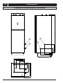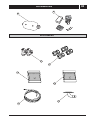
1
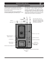
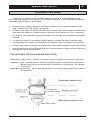
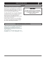
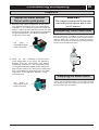
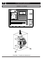
,167$//$7,21$1'0$,17(1$1&(,16758&7,216 :$7(56285&(+($73803 $//,121( 3OHDVH UHDG WKLV RSHUDWLRQ PDQXDO EHIRUH XVLQJ WKH+HDW3XPS 1 Contents System description Principle of operation ............................................ 3 Unit Description .................................................... 3 Principle of heatpump ........................................... 4 Control panel Layout .................................................................. Explanation .......................................................... Functions ............................................................. Symbols ............................................................... 5 5 6 6 General information for the installer Transport and storage ............................................ 7 Installation .............................................................. 7 Inspection of the installation .................................. 7 Pipe connections General .................................................................. 8 Pipe connection (collector) .................................... 8 Pipe connection (Room water side) ...................... 9 Pipe connections (water heater) ............................ 9 Pump capacity diagrams, Room water side ........ 10 How to adjust the rate of flow .............................. 10 Pump capacity diagrams, collector side .............. 11 Electrical connections Connect the power cord ....................................... 12 Wiring of the terminal (mode one) ......................... 13 Wiring of the terminal (mode two) ......................... 13 Connecting the room temperature sensor ........... 14 Connecting the outside temperature sensor ........ 14 Layout of the PCB ............................................. 15 1.5mm2 terminal connection ............................. 15 Part of wiring diagram ........................................ 16 2.5mm2 / 6mm2terminal connection ................... 16 Wiring diagram ( 3X400v / 3 / 50 Hz ) ................... 17 Description of the switch board .............................18 Commissioning and adjusting Preparations ........................................................ 19 Filling the room water cycle system .................... 19 Inspection ............................................................. 20 Adjust the Water source / Room water cycle pump ...... 20 Readjusting, Room water side .............................. 20 Emptying the water heater ................................... 20 Control General Information .............................................. 21 Menus ................................................................... 22 Main Menu Information ......................................... 22 Sub-menu Operation.............................................. 22 Sub-menu Heat Curve ........................................... 23 Sub-menu Temperature ........................................ 24 Sub-menu Integral ................................................. 24 Degree Minute's(DM) instruction .......................... 25 Sub-menu Operating Time .................................... 27 Sub-menu Reset ................................................... 28 Sub-menu Man Test .............................................. 28 Adjustments to be made regularly ........................ 28 Heat Generation-General....................................... 28 Adjustment of the CURVE valve ........................... 29 Adjustment of ROOM valve.................................... 31 Adjustment of Part of the Heat Curve .................... 31 Adjustment the MIN and MAX valve ..................... 32 Adjustment of the HEAT STOP valve......................33 Graph of recent change in TEMPERATURE............ 34 Maximum Return Line Temperature ..................... 35 Warm water Production........................................... 35 Regular checks .......................................................36 Check of the Operating Mode ............................... 36 Checking the Water Level of the Heating system . 36 Checking the safety valves .................................... 37 In the event of leakage .......................................... 37 Alarm Messages .................................................... 38 Terminology and Abbreviations ............................. 39 Description of the switch board ............................. 40 Dealing with malfunctions Draining, heat medium side ................................ 41 Draining, collector side.......................................... 41 Draining, water tank.............................................. 41 Draining, the chassis............................................. 41 Component placement Component positions 1 ........................................ 42 Component positions 2......................................... 43 Component positions 230 V / 50 HZ .................... 44 Component positions 3 x 400 V / 3 / 50 HZ ......... 45 List of components List of components ................................................ 46 Dimensions Dimensions and setting-out coordinates .............. 47 Accessories Accessories .......................................................... 48 Enclosed kit .......................................................... 48 Technical specifications Technical specifications 230 V ............................ 49 Technical specifications 3 x 400 V ...................... 50 System description 2 Principle of operation Expansion vessel Water in Water out Room-water flow The heat source of the this series is provided from seawater or ground-water. The titanium heat exchanger is used for collecting the heat of water-source. The Water-source emits its heat to the refrigerant in the evaporator. It then vaporises and is compressed in the compressor. The refrigerant, the temperature of which has now been raised, is passed to the condenser where it gives off its energy to the heating medium circuit and, if necessary, to the water heater. After the condenser there is a built-in electrical module which cuts in if there is a high demand. Room-water return This series consists of a heat pump, water heater, electrical module, circulation pumps and a control system. This series is connected to the collector and heating medium circuits. The room water side and the hot water side must be fitted with the necessary safety equipment in accordance with the applicable regulations. Three - way valve Water-source out Water-source in Room-water flow Compressor Room-water Return Water-source Cycle pump Electrical auxiliary heater Room-water Cycle pump Titanium heat exchanger Stainless steel plate heat exchanger Expansion valve 6\VWHPGHVFULSWLRQ 8QLW'HVFULSWLRQ ,Q RUGHU WR JHW WKH EHVW UHVXOWV IURP WKH FOLPDWH V\VWHP WKLVVHULHV \RX VKRXOG UHDG WKURXJK WKH VHFWLRQ)RUWKH6\VWHPPDQDJHULQWKHVH,QVWDOODWLRQDQG0DLQWHQDQFHLQVWUXFWLRQV 7KLVVHULHV LV DFOLPDWHV\VWHPIRU KHDWLQJ KRXVHV DQG DSDUWPHQW EXLOGLQJV DV ZHOO DV LQGXVWULDO SURSHUWLHV *URXQGZDWHUDQGVHDZDWHU FDQ EH XVHG DV WKH KHDW H[FKDQJH VRXUFH 7KLVVHULHV LV D FRPSOHWH KHDWLQJ LQVWDOODWLRQIRUKHDWLQJ DQG KRW ZDWHU ,W LV ILWWHG ZLWK QHZGHVLJQ RQ WKH PDUNHWWREH GHYHORSHG VSHFLILFDOO\IRUKHDW SXPSV $ QHZ HYDSRUDWRU HQDEOHV D QHZ DQG LPSURYHGFLUFXODWLRQ V\VWHPIRUWKH UHIULJHUDQW 7KH KHDW SXPS KDV DQ LQWHJUDWHG RU OLWUH ZDWHU WDQN DQG DQ LPPHUVLRQ KHDWHU 7KH 7DS :DWHU 6WUDWLILFDWLRQ V\VWHP LPSURYHV WKH HIILFLHQF\ RI KHDW WUDQVIHU E\ NHHSLQJ WKH ZDWHU LQ GLVWLQFW WKHUPDO OD\HUV LQ WKH ZDWHU WDQN 7KHXQLWLV ILWWHG ZLWK D UHJXODWLQJ FRPSXWHU ZKLFK LV FRQWUROOHG RYHU D JUDSKLF GLVSOD\ XQLW +HDW LV GLVWULEXWHG WKURXJKRXW WKH KRXVH RYHU D K\GURQLF KHDWLQJ V\VWHPUHIHUUHGWRDV ORZWHPSHUDWXUH V\VWHP ZLWK D PD[LPDO ZDWHU WHPSHUDWXUHWRUDGLDWRUV VXSSO\ OLQH WHPSHUDWXUH RI & 0RVW RI WKH KHDWLQJ GHPDQG LVWDNHQ FDUH RI E\ WKH KHDW SXPS FRPSUHVVRU XQLW WKH DX[LOLDU\ KHDWHU EHLQJ VWDUWHG RQO\ ZKHQ GHPDQGV H[FHHG DYDLODEOH KHDW SXPS FDSDFLW\ 7KLVVHULHV FRQVLVWV RI ILYH PDLQ FRPSRQHQWV D +HDW 3XPS 8QLW 5RWRU\RU6FUROOFRPSUHVVRU 6WDLQOHVV VWHHO KHDW H[FKDQJHUV &LUFXODWLRQ SXPSVIRU:DWHUVRXUFH V\WHP DQG KHDWLQJ V\VWHPV 9DOYHV DQG VDIHW\ HTXLSPHQWIRUUHIULJHUDQW V\VWHP FRPSOHWH ZLWKQHFHVVDU\ HOHFWULF FRPSRQHQWV E :DWHU+HDWHUFRROHU RUOLWUH /LQHG ZLWK FRSSHU VKHHW DJDLQVWFRUURVLRQ RU PDGH RI VWDLQOHVV VWHHO 0DLQWHQDQFH IUHH DV QR DQRGH LV XVHG F 5HYHUVLQJ 9DOYH 2SHQLQJ RU FORVLQJ WKH FRQQHFWLRQWRZDWHU KHDWHU DFFRUGLQJWRRSHUDWLQJPRGH KHDWLQJ RU ZDUP ZDWHU SURGXFWLRQ G $X[LOLDU\+HDWHU N: HOHFWULF KHDWLQJ HOHPHQW 7KUHHVWHS FDSDFLW\ FRQWURO )LWWHG RQ VXSSO\ OLQH 'HOLYHUV EDFNXS KHDW LQ FDVH RI JUHDW KHDW GHPDQG WKDW H[FHHGV KHDW SXPS FDSDFLW\ H 5HJXODWLQJ (TXLSPHQW 7KH UHJXODWLQJ V\VWHP FRQWUROV KHDW SXPS FRPSRQHQWV FRPSUHVVRUFLUFXODWLRQSXPSV DX[LOLDU\ KHDWHU DQG UHYHUVLQJ YDOYH %DVHG RQ GDWD UHFHLYHG IURPVHQVRUV LW VWDUWV RU VWRSV KHDW SXPS RSHUDWLRQ DQG GHWHUPLQHV ZKHWKHU KHDWLQJ RU ZDUP ZDWHU VKDOO EH SURGXFHG 7KH V\VWHP FRQVLVWV RI &RQWURO FRPSXWHU ZLWK JUDSKLF GLVSOD\ XQLW 7HPSHUDWXUH VHQVRUV RXWVLGH DLUURRP VXSSO\ OLQH UHWXUQ OLQHDQG:DWHUVRXUFH V\VWHP System description 4 Principle of heat pump A heat pump can exploit the energy contained in natural heat sources. Or, to put it differently, the heat pump ”collects” heat energy from the heat source. This makes the heat pump a very environmentally friendly and economically sound alternative for space heating. a. The Water-source cycle sytem absorbs the heat energy of the heat source so that the temperature of the water circulating in the hose is raised a few degrees. b The Water-source sytem is circulated to the heat pump’s evaporator. Here the heat energy of the Water-source sytem causes the refrigerant, circulating through the evaporator, to boil and turn into a gas – it evaporates. c The refrigerant, having absorbed heat energy, is circulated to the compressor where pressure and temperature are raised. d The refrigerant continues to the condenser. When condensing, it releases heat energy to the heat carrier, circulating through the condenser. The temperature of the refrigerant sinks, and it returns to its liquid state. e The heat energy released is carried by the heating circuit to water heater and radiator or floor heating systems. f At last the refrigerant is led through the expansion valve, where its pressure is reduced, and then continues to the evaporator The process is restarted. . The heat pump has three separate liquid circuits Water-source sytem circuit – The Water-source system transporting energy from heat source to heat pump. Refrigerant circuit – circulating inside the heat pump. Through evaporation, compression and condensation it absorbs energy from the ground-water sytem and releases it to the heat carrier. The refrigerant is chlorine-free. Room-water system circuit – water transporting heat energy to the heating system (radiators/floor coils) and the water heater. Room-water system circuit Water-source system circuit Water-source system &RQWUROSDQHO /D\RXW 5220 'LVSOD\ 8S EXWWRQ R & /HIW EXWWRQ & ' 5LJKW EXWWRQ ) 3RZHU2Q2II $ 'RZQ EXWWRQ ([SODQDWLRQ &RQWURO 3DQHO 7KH FRQWURO SDQHO IHDWXUHV D JUDSKLF GLVSOD\ ILYH FRQWURO EXWWRQV %HVLGH WKH FRQWURO SDQHO \RX ZLOO ILQG WKH 8VHU¶V 0DQXDO D VKRUW GHVFULSWLRQ RI KRZWRLQFUHDVH DQG UHGXFH URRP WHPSHUDWXUH DQG D ODEHO ZLWK QDPH DQG SKRQH QXPEHU RIGHDOHU 5220 R & 23(5$872 *UDSKLF GLVSOD\ Control panel 6 Functions The control computer is operated with the help of a user friendly menu system that is displayed on the contr ol panel. There is a main menu and four sub-menus accessible from the main menu. The menus are described in detail further down. To be able to select the desired menu and increase or reduce preset values, you will use the five buttons. • • • • • One butto n poin ting One button pointing One button pointing One button pointing One button pointing upwar ds marked with a plus downwards marked with a minus to the right to the left to the Power ON/OFF Symbols For you to know at a glance the actual operating mode of the heat pump, one of the followingsymbols will be shownin the lower part of the display depending on whichpart of the unit is working: The heat pump is running. Warm water is being produced. The auxiliary heater is activated. The figure next to the symbol indicates capacity step. Indicates the status of warm water production. If the symbol is empty, warm water temperature is under the setting temperature. There is a room heating demand. If the symbol is full, warm water temperature reached to the setting temperature 7 General information for the installer Transport and storage This series must be transported and stored upright and dry. This series may however be carefully laid on its back when being moved into a building. H M flo w4 9 (5 0°C ) H o t w a te r 5 1°C -2 0 +2 1 0 R 0 +2 0 -2 H M flo w 4 9 (5 0°C ) H o t w a te r 5 1°C 1 R Installation This series is placed on a firm base, preferably a concrete floor or foundation. Install this series with its back to an outside wall, ideally in a room where noise does not matter. If this is not possible, avoid placing it against a wall behind a bedroom or other room where noise may be a problem. Any wall that backs on to a bedroom should be fitted with sound insulation. Route pipes so they are not fixed to an internal wall that backs on to a bedroom or living room. Inspection of the installation Current regulations require the heating installation to be inspected before it is commissioned. The inspection must be carried out by a suitably qualified person and should be documented. The above applies to closed heating systems. If the heat pump is replaced, the installation must be inspected again. Pipe connections 8 General Pipe installation must be carried out in accordance with current norms and directives. The heat pump can operate up to a return temperature of about 58* °C and an outgoing temperature of about 70* °C from the heat pump. The compressor produces up to 65* °C, the rest is obtained using additional heating. The other heat pumps has a max return temperature of approximately 50 °C and an outgoing max temperature from the heat pump of approximately 60 °C. Since this series is not fitted with shut-off valves, these must be fitted outside of the heat pump to make future servicing easier. During assembly the pipes for the heat medium and water heater and possibly hot water circulation are routed backwards. The distance between this series and the wall ought to be 50 mm. NOTE! 7KHSLSHV\VWHPQHHGVWREHIOXVKHG RXWEHIRUHWKHKHDWSXPSLVFRQQHFWHG VRWKDWGHEULVFDQQRWGDPDJH FRPSRQHQWSDUWV Pipe connections (collector) Factors to be taken into account when designing the collector layout are geographical position, type of ground water and cover factor of the heat pump. All collector pipes in heated rooms must be insulated against condensation. The temperature of the Water-source system must be between -12 °C ---- 10 °C .The default is -12 °C 9 Pipe connections Pipe connections (Room water side) Pipe connections for the heat medium side are made at the top. All required safety devices, shut-off valves (as close to the heat pump as possible), and particle filter (supplied) are fitted. When connecting to a system with thermostats on all radiators, a relief valve must be fitted, or some of the thermostats must be removed to ensure sufficient flow. Pipe connections (water heater) The heat pump´s water heater must be fitted with the necessary valve equipment. VENTING VALVE P EXP SAV Ground-water HW CW SAV SF Water-source in Water-source out SF Water-source Water-source in SF Particle filter Water-source out SF Particle filter The heat pump should be supplemented with an electric water heater if a bubble pool or other significant consumer of hot water is installed. The valve coupling in COMPACT (electrical water heater) can be divided. The mixing valve stays in COMPACT and the remaining valve coupling can be used for incoming cold water in this series. NOTE! 7KHYHQWLQJYDOYHVKRXOGEHVHWRQ WKHWRSRIWKHKHDWLQJPHGLXPV\VWHP 10 Pipe connections Pump capacity diagrams, Room-water side 6kW ~ 12kW 16kW Available pressure Available pressure kPa kPa 80 70 60 50 40 30 20 10 0 80 70 60 50 40 30 20 10 0 1 2 3 Flow 0 0.22 0.44 0.66 0.88 1.10 1.32 1.54 1.76 l/s 2 1 3 Flow 0 0.28 0.56 WILO RS-25/8 0.84 WILO RL-25/7.5 1.12 1.4 1.68 WILO RL-25/7.5 How to adjust the rate of flow WILO RS-25/8 Tillgängligt tryck The pump is adjustable to adjust the flow: 1, 2, or 3. The pump is adjustable to adjust the flow: 1, 2, or 3. 1.96 2.24 l/s 11 Pipe connections Pump capacity diagrams, collector side 6kW ~ 16kW Available pressure kPa 80 70 60 50 40 30 20 10 0 1 2 3 Flow 0 0.22 0.44 0.66 0.88 1.10 1.32 WILO RS-25/8 WILO RS-25/8 The pump is adjustable to adjust the flow: 1, 2, or 3. 1.54 1.76 l/s Electrical connection 12 Connect the power cord N TS L G R G N N ( 230V / 50 HZ ) NOTE! (OHFWULFDOLQVWDOODWLRQDQGVHUYLFHPXVW EHFDUULHGRXWXQGHUWKHVXSHUYLVLRQRI DTXDOLILHGHOHFWULFLDQLQDFFRUGDQFH ZLWKWKHVWLSXODWLRQVLQIRUFH ( 3X400V / 3 / 50 HZ ) 13 Electrical connection Wiring of the terminal (mode one) Step1 Step2 Step3 Wiring of the terminal (mode two) Step1 Step2 Step3 Electrical connection 14 Connecting The Room Temperature Sensor RT OCT Room temperature sensor Room temperature sensor RT=Room temperature sensor Connecting The Outside Temperature Sensor RT OCT Outside air temperature sensor Outside air temperature sensor OCT=Outside air temperature sensor From PCB / CON5 /5,6 From PCB / CON5 /7,8 WTT WSIT COMP HP LP From Water source Inlet Temperature Sensor From Water Tank Temperature Sensor From Water source Outlet Temperature Sensor From Compressor Gas Outlet Temperature Sensor From High Pressure Pressostat From Low Pressure Pressostat From Water cycle pump2 GND N WCP2 From From Neutral line common terminal From Fuse 3 CON3 N OUT1 GND OUT2 WSCP2 COM OUT3 GND CON1 N COM From Water source cycle pump2 WCP PCB N COM From Fuse 2 From Neutral line common terminal From From Fuse 3 From Neutral line common terminal From GND NO From Water cycle pump From WSCP NO From water source cycle pump EHI From Neutral line common terminal From Fuse 2 From Neutral line common terminal 10 11 12 N 9 Water Return Temp 8 From Three-way valve forwaterflow CSP 7 From Fuse 1 6 3WV 5 Water Feed Temp 4 From PCB / CON5 /11,12 3 OUT5 From Electrical auxiliary heater Temperature Sensor 2 Water Source Outlet Temp 1 From Water Source Inlet Temp OUT6 GND High Pressure Outdoor Condition Temp Compressor Gas Outlet Temp Room Temp Water tank Temp Low Pressure OUT7 From PCB / CON5 /9,10 From PCB / CON5 /1,2 From PCB / CON4 /1,2 Electric Heater interruptor From Adjustable pressure switch From PCB / CON5 /3,4 WSOT From PCB / CON4 /7,8 From PCB / CON4 /9,10 WIT From Water Feed Temperature Sensor Compressor stoped protection CON5 From PCB / CON4 /11,12 Compressor interruptor 16 15 14 13 12 11 10 9 8 7 6 5 4 3 2 1 WOT From Water Return Temperature Sensor 15 Electrical connection Layout of the PCB NO OUT4 CON2 CON4 TRANSFORMER R S T N L C D 1.5mm2 terminal connection Electrical connection 16 Part of wiring diagram Water source Cycle Pump L3 T3 L2 L1 BLACK C1 w WHITE T2 cm u RED T1 v WSCP2 2.5mm2 terminal connection From Electrical heater 1 From Electrical heater 2 EH1 From Fuse 4 EH2 From Fuse 5 N From 6mm2 terminal / N EH3 From Compressor / W W From Fuse 6 From Neutral line common terminal From AC contactor / L1 From Compressor / U U From AC contactor / L2 From Compressor / V V From AC contactor / L3 From Electrical heater 3 From Compressor N GND From Water tank Temp Room Temp OUT5 O UT4 CON4 Water Feed Temp P CB O U T6 Outdoor Condition Temp OUT7 Water Source Outlet Temp Electric Heater interruptor Compressor stoped protection Low Pressure High Pressure Compressor Gas Ooulet Temp Water Source Inlet Temp Water Return Temp cm CON3 R CON2 O U T2 R BLACK WHITE RED C2 BLACK T1 BLACK AO AA BA BLACK L1 Switch board 3A F3 3A F2 2A F1 16A F5 16A F4 4 3 Relay 6 5 2 1 A2 BLUE Water Source cycle pump 8 7 BROWN 3 way valve C1 COMPRESSOR CONTACTOR BLUE BLACK WHITE Water cycle pump A1 Heater 2 Heater 1 Neutral line common terminal BLUE BLUE C N N AC-N OUT1 Compressor Capacitor S TRANSFORMER CON1 BLACK WHITE BLACK BLACK BLACK BLACK Y/G Y/G W SCP2 N Y/G WCP2 N BLACK BLACK C1 CON5 N BLACK BLUE K1 L 17 Electrical connection Wiring Diagram( 230V / 50 HZ ) 230V 50Hz Electric Heater interruptor Compressor stoped protection Low Pressure High Pressure Compressor Gas Ooulet Temp Water Source Inlet Temp Water Source Cycle Pump :6&3 Electrical connection Wiring Diagram ( 3X400V / 3 / 50 HZ ) 18 Water Return Temp Water Source Outlet Temp Water Feed Temp Outdoor Condition Temp Water tank Temp Room Temp 19 Commissioning and adjusting Preparations Before starting up the system, check that the heating, collector and hot water circuits are full and thoroughly vented. Check the pipe system for leakage. Filling the room water cycle system 11. Stop the filling pump and clean the particle filter. 12. Start the filling pump, open the valve between the service connections. 13. Close the valve on the service connection's return line. Now pressurise the system (to max 3 bar) with the filling pump. 14. Close the valve (AV2) on the service connection. 15. Stop the filling pump. 16. Select the auto operating mode using the operating mode button. 1. Check the heating medium system for leakage. 2. Connect the filling pump and return line on the heating system's service connections as shown in figure. 3. Close the valve between the service connections. 4. Open the valves on the service connections(AV1,AV2). 5. Pushing the white manual lever down to bottom (this has already been done when the machine leaves factory), then three way valve's water tank port is closed (the "B" port), room heat port is open (the "A" port). 6. Start the filling pump, and fill until there is fluid in the return pipe. 7. Open up Power ON from control panel to start machine, then heat medium water pump is running, the valve will return to the up position when power is restored. 8. Firmly pushing the white manual lever down to midway and in. in this position both the 'A' and 'B' ports are open. 9. The filling pump and the heating medium pump are now operational. The fluid should circulate via the container with tap water until it emerges from the return hose without being mixed with air. AV Closes AV AVT AV SF SÄV CW HW NK 10. Stop machine, heat medium water pump stop running. Depressing the white manual lever lightly and then pulling the lever out, pushing the while manual lever down to bottom position, and then "A" port open, "B" port is closed. AVT SÄV Draining Safety valve SF Particle filter NK Level vessel Commissioning and adjusting 20 Inspection Adjust the Water source/ Room water cycle pump 1). Read the water source temperatures on the panel. The defference between these two temperatures should be 2—5°C when the system has come into balance. Adjust the flow with the knob on the water source cycle pump (32). A high difference indicates a low ground water flow. A low difference indicates a high water source flow. The pump is adjustable to adjust water source flow. 2). Check the flow temperature and the return return temperature on the panel. The difference between these two temperatures, with floating condensing, should be 5 — 10 °C when the house is being heated without additional heat. Adjust the flow with the knob on the room-water cycled pump (34). A high difference could depend on a low roomwater flow. A low difference indicates a high room-water flow. NOTE! 7KHFRPSUHVVRUPXVWQRWEHIRUFHGWR VWDUWZLWKSHULRGVVKRUWHUWKDWVWDUW SHUPLQXWHV Readjusting, Room water side Air is initially released from the hot water and venting may be necessary. If bubbling sounds can be heard from the heat pump, the entire system requires further venting. When the system has stabilised (correct pressure and all the air removed) the heating controls can be set at the required values. 2/3 Emptying the water heater The pump is adjustable to adjust Room-water flow. The siphon principle is used to empty the water heater. This can be done either via the drain valve on the incoming cold water pipe or by inserting a hose into the cold water connection. 21 Control General information Menu Navigation The right-hand button on the con trol panel is used to open the desired menu. The left-ha nd button is used to return to the pr evious men u. The up and down butt ons are used to navigate betw een the parameters of a menu. A cu rs or (arrow) on the left-hand side of the display indica tes which me nu can be op en ed . The up and down buttons are also used if you wish to increase or reduce a preset value. Display of current operating mode During normal operation, the following in formation will be displayed: • Desired (preset) room temperature • Whether there is a heating demand or not. If there is, there will also be symbols telling which heat source is working– heat pump or auxiliary heater or both (see ”Symbols” on page 6) . OPER. AUTO • Which operating mode has been selected In addition to this, the following messages may be displayed: • POWER SUPPLY The compressor in the heat pump is running in the wrong direction, which means that heat is produced by the auxiliary heater only (see ”Alarm” on page 38). Control 22 Menus Main Menu INFORMATION To open the main menu INFORMATION, press the right- or left-hand button once. Return Open next menu INFORMATION OPERATION HEATCURVE TEMPERATURE INTEGRAL OPER TIME RESET MAN TEST Sub menus . To select the desired sub-menu use the up or down button. Open the menu by pressing the right-hand button once. To return to the main menu, press the left-hand button once. Sub-Menu OPERATION OPERATION AUTO ROOMHEAT WARMWATER HEATPUMP ADD HEAT . ON OFF This menu is used for the selection of operating mode. The control system allows for five different operating modes: • OPERATION HEAT PUMP ON Heat pump (compressor) operation is allowed by the control system. • OPERATION HEAT PUMP OFF Heat pump (compressor) operation is not allowed by the control system. • OPERATION ADD.HEAT ON/OFF The auxiliary heater will/will not be allowed to operate. This operating mode is normally used when a new installation is being put into service, before the Brine system is ready for use. • OPERATION AUTO Heat pump and auxiliary heater are regulated automatically by the control system. The text “OPERATION AUTO” will be displayed on the control panel. • OPERATION ROOMHEAT The heat pump will be distributed to the heating system only; The heat pump will not produce warm water. The text “OPERATION WARMWATER ” will be displayed on the control panel. • OPERATION WARMWATER The heat pump will only produce warm water; no heat will be distributed to the heating system. The text”OPERATION WARMWATER “will be displayed on the control panel. 23 Control Menus • OPERATION OFF Heat pump is turned off. The following text is displayed on the control panel: “OPERATION OFF “ If the heat pump will be put in OPERATION OFF mode during winter, please remember to let out all the water the heating system to avoid any damage caused by freezing. If you wish to change operating mode: a. Open the main menu INFORMATION by pressing the right- hand button once. You will find the sub-menu named OPERATION. b. Open the OPERATION menu by pressing the right-hand button once. c. Select the desired mode by pressing either the ”up” or ”down” button. d. Return to the main menu by pressing the ”up” button until to the top,and press left-hand button twice. Sub-Menu HEAT CURVE This menu is used for making adjustments that affect the room temperature.For more information, please refer to ”Adjustments to be made regularly” on page 26. HEATCURVE CURVE MIN MAX CURVE 5 CURVE 0 CURVE - 5 HEAT STOP 40 22 70 0 0 0 17 Table 1: Menu– HEAT CURVE Menu Text Description Adjustable by: The value entered shows the temperature of the water to be distributed to the radiators(supply line temperature) when the outside air temperature is 0°C. User (see”Adjustment of CURVE value” on p. 29) MIN Adjustment of value for lowest supply line temperature allowed. User (see ”Adjustment of MIN and MAX values” on p. 32) MAX Adjustment of value for highest supply line temperature allowed. User (see ”Adjustment of MIN and MAX values” on p. 32) CURVE 5 Adjustment of room temperature when the outside air temperature is +5°C. User (see ”Adjustment of CURVE value” on p. 32) CURVE 0 Adjustment of room temperature when the outside air temperature is 0°C. User (see ”Adjustment of CURVE value” on p. 32) CURVE – 5 Adjustment of room temperature when the outside air temperature is -5°C. User (see ”Adjustment of CURVE value” on p. 32) Production of radiator heat is stopped when outside air temperature is equal to or higher than the value for heat stop entered User, if require CURVE HEAT STOP Control 24 Menus Sub-Menu TEMPERATURE This menu shows the different temperatures of the heating system. All temperature changes registered over the last 60 minutes are stored in the control system and can be viewed in the shape of graphs. TEMPERATURE - 20 20 41(70) 38(45) 53(44) 24(-12) 25(-12) OUT ROOM FEED RETURN WARMWT WT OUT WT IN Table 2: Menu TEMPERATURE Menu Text Description Adjustable by: OUT Outside air temperature ROOM Desired (setpoint) room temperature User (see ”Adjustment of ROOM value” on page 31). FEED Actual (measured) supply line temperapture of heating system; in brackets the setpoint (desired) value. User (The temperature necessary to keep the desired room temperature is determined by the control system). RETURN Measured return line tem perature of heating system; in brackets the maximum return temperature allowed. Installation contractor.To be adapted to each individual unit WARMWT Measured warm water temperature; in brackets the starting temperature for warm water production. WATER IN WATER OUT ------- adjustable. Temperature of water source sytem when entering the heat pump. Temperature of water source sytem when leaving the heat pump. Sub-Menu INTEGRAL INTEGRAL OFF CMP A ADD1 ADD2 ADD3 . 00 -60 -500 -550 -600 00 ( 00) ( -60) ( -500) ( -550) Not adjustable. Not adjustable. 25 Control Menus Menu Text Description Adjustable by: OFF When the value (testing) reaches the value setting by user, the system will be closed. USER CMP.A When the value (testing) reaches the value setting by user, the compressor will be start-up.And the value(testing) under the value(setting),the compressor will be closed. USER ADD1 When the value (testing) reaches the value setting by user, the ADD1 will be start-up.And the value(testing) under the value(setting),the ADD1 will be closed. USER ADD 2 When the value (testing) reaches the value setting by user, the ADD2 will be start-up.And the value(testing) under the value(setting),the ADD2 will be closed. USER ADD 3 When the value (testing) reaches the value setting by user, the ADD3 will be start-up.And the value(testing) under the value(setting),the ADD3 will be closed. USER Degree Minute s(DM) instruction Degree Minute = The corresponding value of temperature difference between the actual water supply and the desired water supply X time (through integral to change; every minute for a cumulative) Temperature difference between the actual water supply and the desired water supply ( ć ) -31 ~ -40 -21 ~ -30 -11 ~ -20 -1 ~ -10 1 ~ 10 11 ~ 20 21 ~ 30 31 ~ 40 The corresponding value -40 -30 -20 -10 10 20 30 40 For example: (Under desired temperature) Actual water supply temperature decrease 1ć (under desired temperature) in 1 minutes, Degree Minute=-10 X 1= -10; Actual water supply temperature continue decrease 2ć(under desired temperature) in another 1 minutes, Degree Minute=-10 X 1 + (-10) = -20; Actual water supply temperature continue decrease 3ć(under desired temperature) in another 1 minutes, Degree Minute=-10 X 1 + (-20) = -30; Actual water supply temperature continue decrease 4ć(under desired temperature) in another 1 minutes, Degree Minute=-10 X 1 + (-30) = -40; …………………… Control 26 Degree Minute s(DM) instruction Before the Degree Minute reach - 60 (adjustable) ,the compressor is off, but when the Degree Minute reach - 60 (adjustable) ,the compressor automatic start,and the flow teperature will begin increase. (Higher than desired temperature) when the actual water supply temperature reach / higher than the desired temperature, the DM will be changed. For example : the DM was cumulated to -160 in this time. 1 minutes later when the actual water supply temperature higher than desired temperature for 1ć. 10X1=10 ,Degree Minute= -150; Another 1 minutes later when the actual water supply temperature higher than desired temperature for 2ć. 10X1=10,Degree Minute=-140; Another 1 minutes later when the actual water supply temperature higher than desired temperature for 3ć. 10X1=10,Degree Minute=-130; Another 1 minutes later when the actual water supply temperature higher than desired temperature for 4ć. 10X1=10,Degree Minute=-120; …………………… Compressor off when Degree Minute reach 0 (adjustable) . The relationship between compressor and DM The relationship between compressor (on and off) and DM,the relationship between heater(on and off) and DM. The above diagram describe the relationship between compressor (on and off) and Degree Minute, the relationship between heater(on and off) and Degree Minute. Compressor ‘s Degree Minute are :-60 (on) and 0(off),A0=-60 (on) Heater 1’s Degree Minute are : ‘-500’(on) and ‘-60’(off), A0+A2=-60-440=-500 (on) Heater 2’s Degree Minute are : ‘-500’(on) and ‘-500’(off) Heater 3’s Degree Minute are : ‘-600’(on) and ‘-550’(off) When ambient temperature more than 6ć,heater can not automatic start When flow temperature less than 15ć, heater can start at once,and the sequence of three heaters’ start will extremely follow own Degree Minute. 27 Control Menus Sub-Menu OPERATING TIME OPERATION TIME HEATPUMP ADD1 ADD2 ADD3 WARMWT 2 1 0 0 0 H H H H H Table 3: Menu OPERATING TIME Menu Text Description Adjustable by: HEATPUMP Total operating hours of heat pump since installation. Operating time will not be reset to zero. USER ADD 1 Total operating hours of auxiliary heater (3kW) since installation. Operating time will not be reset to zero. USER ADD 2 Total operating hours of auxiliary heater (6kW) since installation. Operating time will not be reset to zero. USER ADD 3 Total operating hours of auxiliary heater (9kW) since installation. Operating time will not be reset to zero. USER Total operating hours of water heater since installation. Operating time will not be reset to zero. USER WARMWT Control 28 Menus Sub-Menu RESET Reset to factory setting value. Sub-MenuMAN TEST MAN TEST ADD1 ADD2 ADD3 HEAT PUMP 3 WAY WT SOURCE PUMP ROOM WT PUMP OFF OFF OFF OFF OFF OFF OFF How to enter the Sub-Menu MAN TEST: You need to choose the "MAN TEST"on the main menu ( INFORMATION) And press the right button for 3 second . The Sub-Menu MAN TEST contains ADD1 / ADD2 / ADD3 / HEAT PUMP / 3 WAY / WATER SOURCE PUMP / ROOM WATER PUMP ; You can choose ON / OFF to control the each part for testing. Adjustments to be made regularly Most settings will be made by the installation contractor in connection with installation. Adjustments to be made regularly by the user are the following: • Selection of operating mode • Adjustment of desired room temperature by changing the ROOM value. • Adjustment of heat curve • Adjustment of maximum and minimum values for supply line temperature Adjustment of the value for HEAT STOP is possible. (Please refer to ”Adjustment of HEAT STOP value” on p. 31). Heat Generation- General The indoor temperature should be adjusted by changing the heat curve of the installation. The control computer determines the correct temperatur e of the water to be distributed to the heating system based on the heat curve. The heat curve will be adjusted in connection with installation. It must be adapted later on, however, to obtain a pleasant indoor temperature under any weather condition. A correct heat curve reduces maintenance and saves energy. The heat curve determines the supply line temperature depending on the outside air temperature. The lower the outside air temperature, the higher the supply line temperature. In other words, the temperature of the water fed to the radiators will increase exponentially as the outside air temperature falls. If you select CURVE in the sub-menu named HEAT CURVE, a diagram will be displayed. It represents the relation of outside air temperature to supply line temperature. This relation is referred to as heat curve. 29 Control Adjustments to be made regularly Heat curve Supply line temperature 40 C CURVE 18 64 56 Relation of outside air temperature to supply line temperature 48 40 32 24 5 18 -5 0 C Outside air temperature Adjustment of the CURVE value The heat curve will be adjusted by the CURVE value. This value indicates the supply line temperature to the radiators at 0°C outside temperature. At outside air tempe- ratures lower than 0°C, the water sent to the radiators will be warmer than 40°C. At outside temperatures higher than 0°C, the water will be colder than 40°C. When you increase the CURVE value, the heat curve will become steeper and when you reduce it, it will become flatter. This is the most energy and cost efficient way to set the indoor temperature and should therefore be used for long term temperature settings. If you wish to make a temporary change of temperature, you can simply change the ROOM value (see ”Adjustment of the ROOM value” on page 31) . Factory setting of CURVE value is 40°C, at an outside air temperature of 0°C. The value is adjustable between 22°C and 56°C 40 C CURVE 18 64 56 48 40 32 24 Change of value for CURVE 18 5 0 -5 C If you wish to change the CURVE value: 1 Open the main menu INFORMATION by pressing the right- or the left-hand button once. 2 3 You will find the cursor at the sub-menu named OPERATION Press the ”down” button to move the cursor to the sub-menu called HEAT CURVE. Press the right-hand button once to open the menu. You will find the cursor at the parameter CURVE 4 5 Open the selected parameter by pressing the right-hand button once. Increase or reduce the preset value using the ”up” or ”down” button. You will see from the diagram how the gradient of CURVE changes. Press the left-hand button three times to return to the main menu. Control 30 Adjustments to be made regularly When enter ‘Room heat’ mode, user could control compressor and electrical heater through regulate heat curve or DM (degree minute). under a certain ambient temperature ,the time start of compressor is determined by degree minute(DM). Now we are giving two situations to explain. 1.‘start quickly’ is determined by FEED(heat curve) Suppose now the actual supply water’s temperature is 25ć; regulate the heat curve to let the setting of water temperature to be a higher value such as 55ć,that is FEED25(55). At that time, DM (degree minute) decrease -30 per minute, when the DM reach -60, compressor will start right away. (Notice: if the water temperature setting is lower than actual temperature of water supply, DM would turn to positive number, and then compressor does not start. Of course, you also can regulate the DM to be near the value for compressor start, such as -20. 40 C CURVE 18 64 turn it up 56 48 40 32 24 18 5 0 -5 C 2. ‘start slowly’ is determined by FEED(heat curve) Suppose now the actual supply water temperature is 25ć,if regulate the heat curve to let the setting of water temperature to be a lower value such as 30ć, that is FEED25(30); at that time, the DM would decrease -10 per minute, the time to reach -60 is becoming longer, only after some time, then compressor can start. You also can regulate the DM to be more far away from the value for compressor start, such as (-100) 40 C CURVE 18 64 56 48 40 32 curve is a little flat 24 18 5 0 -5 C When enter room heat mode, it needs customer to regulate the heat curve or DM (degree minute) according to own request. Please notice that room heat mode’s precondition is that ambient temperature more than HEAT STOP’s setting temperature (factory setting is 17ć, adjustable from 0 to 24ć); when supply water temperature is lower than minimum temperature setting of supply water, compressor start forcedly; when supply water temperature reaches minimum temperature setting of supply water, compressor shut forcedly 31 Control Adjustments to be made regularly Adjustment of ROOM value As mentioned above, you can also adjust heat curve and indoor temperature by changing the ROOM value. If you use ROOM value to adjust the heat curve, the gradient does not change, i.e. it doesn’t become steeper or flatter. Instead, the whole curve is moved by 3°C for every degree by which the ROOM value is changed. The relation supply line temperature to outside air temperature will not be affected. The supply line temperature will be increased or reduced by the same number of degrees all along the heat curve. See the following diagram. Adjustment of the ROOM value should only be used for temporary changes of the indoor temperature. For long term settings, the CURVE value should be adjusted as this is the most energy and cost efficient way to set the indoor temperature. For adjusting the heat curve, please refer to the chapter ”Adjustment of the CURVE value” on page 29. Factory setting of ROOM value is 20°C. 40 C CURVE 18 64 56 48 40 32 24 18 5 0 -5 C Changing the ROOM value If you wish to change the ROOM value: 1 2 Press the ”up” or ”down” button once to open the ROOM value for adjustment. Increase or reduce the preset value using the ”up” or ”down” button so that the desired room temperature is reached. Wait for 10 seconds or press the left-hand button once to return to the main menu. Adjustment of Part of the Heat Curve At outdoor temperatures between -5°C and +5°C part of the heat curve may need adjusting if the indoor temperature does not stay at the preset ROOM value. For this reason, the control system includes a function adjusting the curve at three outside temperatures: -5°C, 0°C, +5°C. This function will allow you to increase or reduce the supply line temperature, without affecting the heat curve, at three specific outdoor temperatures. If, for example, the outside temperature is -5°C,the supply line temperature will change gradually in the outdoor temperature range of 0°C to -10°C, maximum adjustment being reached at -5°C. The diagram below shows an adjusted CURVE -5. The point of maximum adjustment is clearly visible. As we have seen, you can choose to adjust the heat curve at three specified out- side air temperatures: -5°C, 0°C and +5°C. The supply line temperature can be changed by plus/minus 5 degrees. Control 32 Adjustments to be made regularly CURVE 34 C 0 CURVE 45 C 0 64 64 64 56 56 56 48 48 48 40 40 40 32 32 32 24 24 24 18 5 0 -5 Change of the value for CURVE +5 C 18 5 0 -5 C 40 C CURVE Change of the value for CURVE -5 18 5 0 -5 0 C Change of the value for CURVE 0 If you wish to change a specific part of the heat curve: 1 2 Open the main menu INFORMATION by pressing the right- or left-hand button once.You will find the cursor at the sub-menu OPERATION. Press the ”down” button to move the cursor to the sub-menu HEAT CURVE. 3 Open the selected menu by pressing the right-hand button once. You will find the cursor at the parameter CURVE. 4 Using the ”up” or ”down” button, select either CURVE 5, CURVE 0 or CURVE -5. 5 Open the selected curve by pressing the right-hand button once. 6 Raise or lower the value, using respectively the ”up” or ”down” button. To return to the main menu, press the lefthand button three times. Adjustment of the MIN and MAX value The MIN and MAX value is the lowest respectively highest value that is allowed for the supply line temperature. Adjusting the minimum and maximum supply line temperature is particularly important if your home has floor heating.If your house has floor heating and parquet floor, the supply line temperature should not be higher than 45°C. Else the floor might get damaged. If you have floor coils and stone tiles, the MIN value should be 22-25°C in summer when no heating is required – to obtain a comfortable floor temperature. If there is a basement to your house, the MIN value should be adjusted to a suitable temperature in summer too, to avoid a humid and chilly basement. In such cases,the value for HEAT STOP needs being adjusted upwards. If you wish to change the MIN or MAX value: 1 Open the main menu INFORMATION by pressing the right- or left-hand button once. You will find the cursor at the sub-menu OPERATION 2 Press the ”down” button to move the cursor to the sub-menu HEAT CURVE 3 4 Open the selected menu by pressing the right-hand button once. You will find the cursor at the parameter CURVE. Press the ”down” button to move the cursor to MIN. 5 Open the selected parameter by pressing the right-hand button once. The cursor is at MIN 6 Raise or lower the value, using the ”up” and ”down” button respectively. 7 Press the left-hand button three times to return to the main menu. Repeat the procedure to change the MAX value, replacing MIN by MAX at step 4. 33 Control Adjustments to be made regularly Adjustment of the HEAT STOP value The HEAT STOP function stops all production av radiator heat when the outside air temperature is equal to or higher than the value entered for heat stop.When the heat stop function is activated, the circulation pump will be turned off except when warm water is being produced. Even if shut off, the pump will be”exercised” during 1 minute a day. Factory setting for heat stop is 17°C.( 0 ~24 °C adjustable ) If you wish to change the HEAT STOP value: 1 Open the main menu INFORMATION by pressing the right- or left-hand button once. You will find the cursor at the sub-menu OPERATION 2 Press the ”down” button to move the cursor to the sub-menu HEAT CURVE 3 Open the selected menu by pressing the right-hand button once. 4 You will find the cursor at the parameter CURVE. 5 Press the ”down” button to move the cursor to HEAT STOP 6 Open the selected parameter by pressing the right-hand button once. The cursor moves to HEAT STOP 7 Raise or lower the value, using respectively the ”up” or ”down” button. 8 Press the left-hand button three times to return to the main menu. Control 34 Adjustments to be made regularly Graph of recent changes in TEMPERATURE All temperatures registered during the last hour can be viewed in the sub-menu TEMPERATURE in the shape of a graph. This will enable you to monitor changes in the different system temperatures. CURVE 45 C 0 64 56 48 40 32 24 18 5 0 -5 C There is a graph available for all temperatures, except for the ROOM temperature,where you can only view the setpoint value. The integral value that is displayed represents the heating system’s energy balance. If you wish to check the TEMPERATURE graphs: 1 Open the main menu INFORMATION by pressing the right- or left-hand button once. You will find the cursor at the sub-menu OPERATION. 2 Press the ”down” button to move the cursor to the sub-menu TEMPERATURE 3 Open the menu by pressing the right-hand button once. 4 You will find the cursor at the parameter OUT. 5 Press the ”down” or ”up” button to move the cursor to the desired temperature. 6 Open the selected value by pressing the right-hand button once. A graph will be shown in the display. 7 Move the cursor along the time axis using the ”up” (plus) or the ”down” (minus) button. The exact temperature at the selected point of time appears at the top of the display. 8 Press the left-hand button three times to return to the main menu. 35 Control Maximum Return Line Temperature The maximum return line temperature, i.e. temperature of the water returning from the heating system, should be adapted to each individual installation. The correct temperature value for your system will be entered by your installation contractor in connection with installation and can be adjusted later. Warm or Cool Water Production The temperature of the water distributed to the water heater is controlled by the regulating pressure switch and cannot be adjusted. Reading of warm water temperature. To check the actual warm water temperature on the display: 1 Open the main menu INFORMATION by pressing the right- or left-hand button once.You will find the cursor at the sub-menu OPERATION. 2 Press the ”down” button to move the cursor to the sub-menu called TEMPERATURE. 3 Open the menu by pressing the right-hand button once. 4 Press the ”down” button to move the cursor to the parameter WARMWATER. 5 Open the selected parameter by pressing the right-hand button once. A graph will be shown of last hour’s warm water temperatures. 6 Press the left-hand button three times to return to the main menu. The value displayed next to the parameter WARMWATER is the actual hot water temperature. The value in brackets is the temperature at which warm water production will start. When the actual temperature falls below that value, warm water production starts. The starting value is not adjustable. Control 36 Regular Checks Check of Operating Mode In the event of an alarm, The background light of LCD will flash and an alarm message will be displayed. ALARM AND.HEAT OVER Check the alarm indicator regularly to make sure that the heat pump works properly. You would not always notice if there is something wrong, as the auxiliary heater would start automatically (provided, of course, operating mode AUTO was selected). For more information, please refer to the chapter ALARM MESSAGES on p. 36. Checking the Water Level of the Room water System The pressure of the Room water system should be checked once monthly. The pressure, shown on the external pressure gauge, should be 1-1,5 bar. If the value is below 0.8 bar with cold water in the system, more water must be added (applies to a closed expansion vessel). To find out where the pressure gauge is located. You can use ordinary tap water for filling the Room water system. In some rare cases the water quality would be unsuitable for this purpose (corrosive or calcareous water). In case of doubt, we would recommend that you call your installation contractor. Don’t use any water treatment additives for the Room water system! Level is too low Level is correct 37 Control Regular Checks Checking the Safety Valves Both safety valves of the heating system should be checked at least four times a year to prevent lime deposits to clog the mechanism. To find out where the safety valves are located. The safety valve of the water heater protects the closed heater against positive pressure. It is fitted on the cold water inlet line, its outlet opening facing down- wards. If the safety valve is not checked regularly, the water heater might be damaged. It is quite normal that the safety valve lets out small amounts of water when the water heater is being charged, especially if a lot of warm water was used previously. To check the safety valves, give the cap a quarter of a turn clockwise until the valve lets out some water through the overflow pipe. If a safety valve does not work properly, it must be replaced. Check with your installation contractor. The opening pressure of the safety valve is not adjustable. In the Event of Leakage In the event of leakage in the warm water lines between unit and water taps, the shut-off valve on the cold water inlet line should be closed immediately. Call your installation contractor . In the event of leakage in the system circuit, turn off the heat pump and call your installation contractor immediately. Control 38 Alarm Messages In the event of an alarm message, try to re-start the unit with the safety switch. If this does not work, try to solve the problem with the help of the table below. Call your installation contractor if you need help. Table : Alarm Messages Message Signification Cause Action RETURN TEMP Return line temperature sensor error; All operation stopped, except circulation pump of heating system. Sensor disconnected; Sensor defective. Check the connections,the wire, or change it . FEED IN TEMP Supply line temperature sensor error; All operation stopped, except circulation pump of heating system. Sensor disconnected; Sensor defective. Check the connections,the wire, BRINE OUT TEMP Brine out temperature sensor error / Defrost temperature sensor error ( for air source heat pump ) . Sensor disconnected; Sensor defective.` Check the connections,the wire, or change it . OUTDOOR TEMP Outside air temperature sensor error; Sensor disconnected; Sensor defective. Check the connections,the wire, or change it . ROOM TEMP Room air temperature sensor error; Sensor disconnected; Sensor defective. Check the connections,the wire, or change it . CMP TEMP Compressor exhaust temperature sensor error; Sensor disconnected; Sensor defective. Check the connections,the wire, or change it . WARM WATER TEMP Water tank temperature sensor error; Sensor disconnected; Sensor defective. Check the connections,the wire, or change it . or change it . Check the wire connection; The wire disconnectted; Refrigerance recharge; Refrigerance leakage, lack of refrigerance; Check the water cycled pump for the room water flow stop in the room cycle. heating system; Or call your installation contractor. HIGH PRESS All operation stopped; High pressure switch cut out; compressor is stopped; No warm water is produced LOW PRESS All operation stopped; Low pressure switch cut out; compressor is stopped; No warm water is produced The wire disconnectted; No refrigerance (leakage out ); Pipe was plugged. Check the wire connection; Refrigerance recharge; Check the pipe system; Or call your installation contractor. CMP OVER All operation stopped; Compressor overload protection The actual current over the contactor ‘s allowed current.Compressor current too large;or the AC contactor current adjust too small.(6K,8K should be adjust to 11A; 10K,12K should be adjust to 14A; 16K,20K,25K,should be adjust to 16A) Check the compressor; Adjust the AC contactor’s current range; Or call your installation contractor. ADD HEAT OVER All operation stopped; Electrical heater overheat . WTPUMP OVER All operation stopped; Water pump overheat . The temperature of the water pump (room heating cycle ) over the max allowed temperature.No water in the cycle system. Check the water cycled pump for the room heating system; Or call your installation contractor. CMP AIR OVER All operation stopped; Compressor exhaust overheat . Lack of refrigerance. Refrigerance recharge; Or call your installation contractor. POWER SUPPLY Phase error; For three-phase, the phase order reversed or wrongly connected. For single-phase, the “ three-phase option port ” in the circuit board is not connected or loose. Check the connections,the wires. Or Call your installation contractor Message Signification Cause Action WATER SOURCE OUT WATER SOURCE FLOW LOW Temperature of Water source leaving heat pump is lower than setpoint value. Compressor is stopped and no warm water is produced. Flow switch not active at latest compressor start. Compressor is stopped and no warm water is produced. The temperature of electrical heater over the Check the water cycled pump for the room max allowed temperature. heating system; Or call your installation contractor. Water flow too low or stoped. The minimum Water source sytem temperature has been reached Water source sytem flow is too low. The system resets automatically when temp. has risen to setpoint value Call installation contractor 39 Control Terminology and Abbreviations Evaporate In the evaporator, energy from the heat source is absorbed by the refrigerant passing through the evaporator. The refrigerant turns into gas. (See ”Heat Pump Principle” on p. 4). INTEGRAL INTEGRAL is the heat balance of the heating system. Production of heat is regulated acc. to a calculated heat demand value. This value is determined by comparing the actual supply line temperature with its calculated (setpoint) value. The difference between the two values is multiplied by the time during which the difference is active. The resul- ting value is referred to as the integral. The integral value is automatically established when heat is being produced. The value can be viewed in the sub-menu TEMPERATURE. Compressor The compressor raises temperature and pressure of the the refrigerant (See ”Heat Pump Principle” on p.4). Condenser In the condenser ,the r efrigerantreleases its heat ener gyto the heatingcircuit. (See”Heat Pump Principle” on p.4) CURVE The CURVE value will be adjusted on the control panel. The value indicates the temperature of the water distributed to the radiators (supply line temperautre) at an outside air temperature of 0°C. Refrigerant Circuit in the heat pump filled with refrigerant that by evapo- ration, compression, and circuit condensation absorbs heat energy from the Water- source sytem circuit and releases it to the Heating circuit. Refrigerant Liquid absorbing energy from the Water-source sytem circuit and releasing it to the heating circuit. (See ”Heat Pump Principle” on p. 4). Radiator Heating element Control The control computer regulates the whole installation. All system settings and computer temperature changes are stored and registered in the computer. Settings are adjusted via the graphic display on the control panel. Heating circuit The heating circuit receives heat energy from the refrigerant circuit and carries it to the water heater or radiator/ floor coil systems. (See further”Heat Pump Principle” on p.4). Heat curve The heat curve is the control computer’s instrument for determining the required supply line temperature of the heating system. Indoor temperature will be adjusted by adjustment of the CURVE value Description of the switch board 40 A0 1 : Control the compressor; AA M : Control the Water source cycle pump; BA M Connect to Fuse 3 AA M Switch board When test or repair the machine, the compressor, Water source cycle pump and water cycle pump can be force manual startup. Connect to Fuse 2 Function of manual switch board: A0 1 Connect to compressor contactor (A1) Function BA M : Control the water cycle pump. Or Connect to the Air break switch ( R ) ( 3X400V / 3 / 50 HZ ) Initial state The initial state of the manual switch board are such buttons ( A0 , AA , BA ), all of them are off.(see the picture). BA M AA M A0 1 Switch board When the machine is running normally,the switch board must be in initial state. NOTE! 7KHPDQXDOVZLWFKERDUGLVXVHRQO\LIWKH QHFHVVDU\IRUWHVWRUUHSDLUZKHQWKH PDFKLQHLVUXQQLQJQRUPDOO\WKHVZLWFK ERDUGPXVWEHLQLQLWLDOVWDWH 41 Dealing with malfunctions Draining, Room water side Close the shut-off valves in Room water system. Open the drain valve ( 68 ). A small amount of water runs out, however, to fully empty the Room water side requires the connector that joins the Room water side and the connection on the heat pump to be loosened a little to allow air to enter so the remaining water can run out. When the Room water is empty the requisite service can be carried out. Draining, water tank First,close the drain valve (68),(69),(70).And then open the drain valve (71). When the water tank is empty the requisite service can be carried out. 68 69 70 71 Draining, collector side When replacing the Water source cycled pump or drive side or when cleaning the pump the collector side should be drained. First,close the drain valve (68),(71).And then open the drain valve (69),(70). When the water tank is empty the requisite service can be carried out. Draining, the chassis The drain-pipe for the chassis is already assembled in advance before leaving the factory. The consumer is required to place the hose at appropriate location. 72 If the operating disturbance cannot be rectified by means of the above, an installation engineer should be called. FIGHTER 1220 73 Component placement 42 for example: 1 7 11 12 4 13 14 6 5 2 3 9 10 8 18 17 16 15 Please Note : The picture for reference only ! 43 Component placement 18 24 27 25 23 28 22 29 26 17 20 19 21 61 63 65 60 51 59 52 53 64 54 58 55 62 40 38 39 45 56 57 46 30 48 31 43 32 35 33 36 50 37 42 49 34 44 47 41 Please Note : The picture for reference only ! Component placement 44 230 V /50 HZ 67 66 Please Note : The picture for reference only ! 45 Component placement 3X400 V / 3 / 50 HZ 67 66 Please Note : The picture for reference only ! List of components 1 2 3 4 5 6 7 8 9 10 11 Top board Right side board Left side board Glass upper door Glass lower door Front board Board for fixing control panel Collector,water source out Collector,water source in Stainless steel adjustable feet Control panel 12 13 14 15 16 17 18 19 20 21 22 23 24 25 26 27 28 29 Control panel Box Connecting wire of control panel Door lock Chassis Sound insulation board Connection,room water return Ø 28 mm Level vessel,connection Ø 28 mm Connection,room water flow Ø 28 mm Water inlet Water outlet Power cord connection hole Temperature sensor connection hole Room temperature Sensor connection Outside air temperature sensor connection Water tank wire groove Temperature sensor ( Water Tank ) Three-way valve for waterflow 30 31 Electrical Auxiliary heater Condenser 32 Expansion valve 33 Adjustable pressure switch 34 Drying filter 35 36 37 38 Heating medium pump Evaporator Water source cycled pump Temperature sensor ( Electrical auxiliary heater ) 39 40 Temperature sensor ( Compressor gas outlet ) Temperature sensor ( heating flow ) 46 41 42 43 44 45 Temperature sensor ( Heating return ) Temperature sensor ( water source inlet ) Temperature sensor ( water source outlet ) Temperature sensor for expansion valve High pressure needle valve 46 47 48 Low pressure needle valve Low pressure pressostat High pressure pressostat 49 50 Oil tank Compressor 51 52 53 54 55 56 Transformer Neutral line common terminal Circuit board AC contactor Capacitor 1.5mm2terminal 57 58 59 2.5mm2terminal 6mm2 terminal 1 Switch board 60 Air break switch cover 61 Fuse 1 for 3 way valve 62 63 Fuse 2 for Water source cycle pump Fuse 3 for Room water cycle pump 64 Fuse 4 for Electrical heater 1 65 Fuse 5 for Electrical heater 2 66 6mm terminal 67 68 69 70 Air break switch Draining valve for heating medium system Draining valve for evaporator Draining valve for water source cycled pump 71 72 73 Draining valve for water tank Draining hole Draining pipe for the chassis 74 75 76 Room temperature sensor Ourside air temperature sensor Connecting for the water tank 77 78 79 80 81 Particle filters Drainpipe Draining connector Level vessel Adjustable three-way valve for waterflow 2 Please Note : The List for reference only ! 47 Dimensions Dimensions and setting-out coordinates 1800 50 600 9 9 8 201 498 8 3 0-50 327 540 489 544 482 480 384 208 280 660 717 455 78 90 62 60 Accessories 48 81 80 Enclosed kit 77 76 74 Outside air temperature sensor Room temperature sensor 75 79 78 49 Technical specifications Technical specifications 230 V IP 21 Type 6 8 Heating Capacity at 7/35 °C ( KW ) 5.84 7.89 Heating Power Input at 7/35 °C ( KW ) 1.44 1.95 Operational voltage (V) 230 V / 50 HZ Starting current, compressor (A) 21 24 Heating current, compressor (A) 6.8 8.6 Operating curr. incl. immersion heater 6 kW (A) 14 14 Output, Water source cycle pump (W) 151 151 Output, heat medium pump (W) 151 151 Connection water source o.d. ø (inch) 1 1/2 Connection heating medium, o.d. ø (mm) 28 Water tank inlet/outlet, o.d. ø (inch) 28 Required ceiling height (mm) 1980 Volume, water heater (litres) 150 Volume, spiral copper pipe (litres) 7.3 Max pressure in storage heater (MPa) 0.9 (9 bar) Max pressure in spiral copper pipe (MPa) 0.25 (2.5 bar) Refrigerant quantity (R407C) (kg) 1.15 1.00 Water source flow (l/s) 0.28 0.39 Max pressure collector system (bar) 3 Operating temperature collector system (°C) -12 +20 Heating medium flow (l/s) 0.41 Max temp. (flow/return circuit) (°C) 68/55 Difference pressostat HP (bar) -7 Cut-out value pressostat HP (bar) 28 Difference pressostat LP (bar) +1 Cut-out value pressostat LP (bar) 0.5 50 Technical specifications Technical specifications 3 x 400 V IP 21 Type 10 12 16 Heating Capacity at 7/35 °C ( KW ) 10.0 11.85 16.0 Heating Power Input at 7/35 °C ( KW ) 2.45 2.948 3.94 Operational voltage (V) 3X400 V / 3 / 50 HZ Starting current, compressor (A) 30 30 35 Heating current, compressor (A) 4.7 6.2 7.0 Operating curr. incl. immersion heater 9 kW (A) 14 14 14 Output, Water source cycle pump (W) 151 205 205 Output, Room water cycle pump (W) 151 151 151 Connection water source o.d. ø (inch) 1 1/2 Connection room water cycle, o.d. ø (mm) 28 Water tank inlet/outlet, o.d. ø (mm) 28 Required ceiling height (mm) 1980 Volume, water heater/cooler (litres) 150 200 200 Volume, spiral copper pipe (litres) 9.8 12.26 12.26 Max pressure in storage heater (MPa) 0.9 (9 bar) Max pressure in spiral copper pipe (MPa) 0.25 (2.5 bar) Refrigerant quantity (R407C) (kg) 1.40 1.25 1.70 Water source flow (l/s) 0.55 0.55 0.55 Max pressure collector system (bar) 3 Operating temperature collector system (°C) -12 +20 Room water flow (l/s) Max temp. (flow/return circuit) (°C) 68/55 Difference pressostat HP (bar) -7 Cut-out value pressostat HP (bar) 30 Difference pressostat LP (bar) +1 Cut-out value pressostat LP (bar) 0.5 0.49 0.57 0.75