1
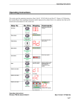
Doc: CB200e User Guide Rev.0 Written By: RP Checked By: AJC Approved By: JBJ Date: 06/05/05 CB200e Extinguishing Control Panel User Instructions Note: to activate controls press 5-1-4. To disable controls, press 5-1-4 again WARNING: This equipment contains hazardous voltages. To avoid electric shock, do not remove the cover. This equipment contains no user-serviceable parts. For servicing, contact suitably qualified personnel. Fire - General The RED zone fire LEDs will pulse, the alarms will sound and the internal buzzer will operate. Locate the source of the fire (an LED will be visible on the detector which has been activated). To silence the alarms, press SILENCE ALARMS. The alarms will silence and the red fire LEDs will change to a steady illumination. When the fire has been extinguished, press RESET SYSTEM. Should the system have activated for no apparent reason, please note which detector has been activated before pressing the RESET SYSTEM button and then contact your service engineer. If necessary, the alarms can be reactivated by pressing EVACUATE. Fire - Zones 1 or 2 - Automatic Mode If a fire is detected on either zone 1 or zone 2, the relevant red zone fire LEDs will pulse and the 1st stage alarms will sound. If a fire is detected on both zones 1 & 2, both zone fire LEDs will pulse, the 1st stage alarms will sound, nd the 2 stage alarm will pulse and the TIMER ON LED will pulse to show that the Extinguishant Release Timer is running. When the Timer ends the TIMER ON LED will be extinguished, the ACTUATOR OPERATED LED nd will illuminate, the pulsing 2 stage alarm will change to continuous and the Extinguishant will be released. The Timer can be stopped & the Extinguishant Release prevented by operating an Emergency Abort switch. The Abort LED will pulse and the Abort condition will remain until the Abort switch and panel are reset. Fire - Zones 1 or 2 - Manual Mode If a fire is detected on either zone 1 or zone 2 or on both zones, the relevant red zone fire LEDs will pulse and the 1st stage alarms will sound. The Extinguishant Release Timer will not start. In this case the Extinguishant can only be released by operation of a Manual Release call point or switch. Automatic or Manual Mode - Manual Release If a Manual Release switch is operated, the Manual Release LED will pulse, the 2nd stage alarms will pulse and the TIMER ON LED will pulse to show that the Extinguishant Release Timer is running. When the Timer ends the TIMER ON LED will be extinguished, the ACTUATOR OPERATED LED nd will illuminate, the pulsing 2 stage alarm will change to continuous and the Extinguishant will be released. The Timer can be stopped & the Extinguishant Release prevented by operating an Emergency Abort switch. The Abort LED will pulse and the Abort condition will remain until the Abort switch and panel are reset. Fault Indication The internal buzzer will pulse and the appropriate fault LED will pulse. Call your service engineer immediately. Press SILENCE FAULT to silence the buzzer. Circuit Isolation To isolate (or de-isolate) a zone, manual release or the actuator circuit, press the ISOLATE button once. The zone 1 fault LED will pulse rapidly every 2 seconds. This is the flashing cursor. Page 1 of 2 Doc: CB200e User Guide Rev.0 Written By: RP Checked By: AJC Date: 06/05/05 Press the ACCESS button to move the flashing cursor to the desired circuit fault LED. Press the ISOLATE button to Isolate or De-isolate the selected circuit. The selected circuit fault LED will illuminate continuously to indicate that the circuit is isolated. Press the RESET SYSTEM button to exit the Circuit Isolate mode. The isolated circuits will remain isolated, the fault Relay will be activated and the buzzer will sound intermittently. The buzzer cannot be silenced. Test Display The RESET SYSTEM button should be operated every week as part of the system test routine for checking correct operation of the panel buzzer and all LEDs. Press and hold to test the LEDs. Test Routine This should be carried out in accordance with BS5839 Part 1. Refer to Fire Alarm System Logbook. User Controls and Indications Zone Fault LEDs, flash for zone fault or device removed, steady for zone isolated Zone Fire LEDs, flash when the zone is in fire, steady once alarms have been silenced Pulses for a fault on the Manual Release Input, steady when isolated Abort Fault LED pulses for any fault on the Abort Input Flashes for a fault on any of the 3 alarm circuits EXTINGUISHANT FIRE ABORT MANUAL RELEASE Toggles the panel mode between Auto & Manual N FAULT C AT IO AUTO/ MANUAL FAULT Z1 Z2 AUX ALARM FAULT PROC FAULT EARTH FAULT SUPPLY HEALTHY BATT FAULT ONE MAN TEST FAULT AUTO ACTUATOR TIMER OPERATED ON MANUAL ZO SILENCE ALARMS/ BUZZER RESET SYSTEM EVACUATE ISOLATE ACCESS 1 2 3 4 5 Pulses for a fault on the Actuator Circuit, Steady when isolated. CONTROLS ACTIVE Flashes when an Earth fault is detected Press to Silence the Alarms during a fire condition. Press to silence the buzzer during a fault condition. Press to Reset Press to Press to the panel after activate activate a fire alarm. circuit isolate code entry Press to test mode mode the LEDs in Press to quiescent activate alarm Illuminates when mode. both the Mains circuits 1 & 2. supply and Battery supply are present Page 2 of 2 Flashes when a Battery fault is detected Illuminates when controls are enabled FAULT Pulses when delay timer is running N E LO Slide-in insert for zone location text Pulses when Manual Release is activated, steady once alarms are silenced Pulses when Abort Input is activated Flashes when Panel is in One-man-Test mode Flashes when a processor fault occurs Illuminates when Actuator circuit is energised Auto & Manual LEDs illuminate to show Auto mode or Manual mode