1
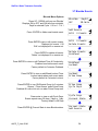
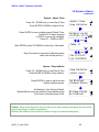
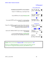
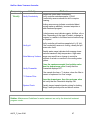
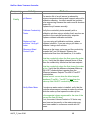
SlimFlex
Water Treatment Controller
For Cooling Towers
Measures Conductivity, pH, Temperature,
Make-up Water Meter and Flowswitch
Controls the Bleed Solenoid,
Inhibitor, Acid and Biocide Pumps
Includes CTF, Conductivity-Temperature-Flowswitch
and pH Sensors
Part No. CO-IN-PH-TB
SlimFlex: Water Treatment Controller
CONTENTS
Safety
1.
INSTALLATION
1.1
1.2
1.3
1.4
1.5
Sample Piping
Controller Enclosure
Sensors –Conductivity & pH
Sensors –Water Meter & Flowswitch
Pumps and Bleed Solenoid
2.
START-UP
2.1
2.2
2.3
2.4
2.5
2.6
2.7
2.8
Power-up Display & Keypad
Bleed Mode: Conductivity Setpoints
Inhibitor Feed Mode: Setpoints, Feed Limits
Acid: Setpoints, Feed Limit
Verify Conductivity & pH Sensors
Check Flowswitch & Install Water Meter
Plug-in Pumps and Bleed Solenoid
Check Controls
3.
OPERATION
3.1
3.2
3.3
3.4
3.5
3.6
3.7
3.8
3.9
Conductivity Sensor
Bleed Controls
pH Sensor
Acid Controls
Make-up Meter
Inhibitor Controls
Biocide Events
System –Alarms
Password
4.
MAINTENANCE
4.1 Guidelines
4.2 Spare Parts
3.10 4.3 Technical Support
APPENDICES
A. INSTALL
B. SPECIFICATIONS
C. HARDWIRING
D. ‘
CL’4-20mA OUTPUT Option
E. ‘
AR’ALARM RELAYOpt
i
on
F. ‘
LB’LAN- BROWSER Option
AQCP_F_User 05/06
2
SlimFlex: Water Treatment Controller
Safety
Electrical Shock Hazard
Removing the lower enclosure cover with the controller plugged in,
exposes the user to AC line voltages.
There are no user serviceable parts behind the upper
enclosure cover; do not remove.
USER WARNING : CAUTION
Cooling Tower Water Treatment Controllers operate 120VAC bleed
solenoids & pumps and may pump hazardous, corrosive and toxic
chemicals.
Opening the controller enclosure exposes user to the risk of electrical shock
at power line voltages.
Understand fully the implications of the control setpoints, feed limits and
alarms that you select. Harm to personnel and damage to equipment may
result from mis-application.
Unplug or turn OFF the AC power to the controller if you have any concerns
regarding safety or incorrect controller operation and notify supervisory staff.
YOUR CONTROLLER
Controllers are supplied with default bleed and feed and oxidant pump
setpoints that will not be applicable to your cooling tower.
Select control modes, adjust setpoints and set biocide pump timing for your
site and its water treatment program.
AQCP_F_User 05/06
3
SlimFlex: Water Treatment Controller
1. INSTALLATION
1.1
Sample Piping
Cont
r
ol
l
eri
ncl
udessensor
sand¾’PVCsens
orent
r
yf
i
t
t
i
ngs.
if you have not previously installed this type controller,
read Appendix A: INSTALL for plumbing and wiring guidelines
CAUTION: Do not exceed 100psi on pH sensor or flowswitch.
Always close upstream isolation valves first.
AQCP_F_User 05/06
4
SlimFlex: Water Treatment Controller
1.2
Controller Enclosure
Remove the lower, controller enclosure cover.
Hang the controller on a single #8-#10 screwl
ocat
ed60”
,150c
m.abov
et
hef
l
oor
Install the bottom left & right mounting screws through the existing enclosure holes located
behind the lower cover.
Flow
Typical Equipment Layout
Controller
Chemical
Injection
points
Chemical Feed Pumps
Plugs, wiring
& tubing not
shown
Pump Shelf
Sensors
Warning:
Sulfuric acid cannot be fed
into PVC piping.
Use a quill rated for acid injection.
Comply with quill vendors
recommended installation
Inhibitor
Biocide
Acid
or
Caustic
Although sensor cables and pump tubing may be extended, ease of servicing occurs when
water treatment components are located in the same area.
Ensure that the lower enclosure cover is installed when not terminating sensor
and water meter wiring.
AQCP_F_User 05/06
5
SlimFlex: Water Treatment Controller
1.3
Sensors –Conductivity & pH
After installing the conductivity and pH sensors, open the sample piping downstream valve,
then the upstream valve.
Verify that both sensor entries seal, leak and drip free
Controllers are supplied with sensors and optional flowswitch pre-wired.
The following graphic details connection points for sensors.
BLU
+15V
BRN
Flow
pH-ORP
Meter
Shield
+
GRN WHT BLK RED
T S1 S2
Red
Black
White
Green
Green
pH
Sensor
Brown
Shield
Blue
Center
pH sensors include a coaxial
cable with tinned ends & a sensor entry
‘
T’
wi
t
hGREEN solution ground
Conductivity
Temperature
&
Flowswitch
Sensor
Controller
Controllers are supplied with
the Sensors prewired
Feed the sensor
cable through
the entry seal & tighten
the seal
Flowswitch Alternative: A dry contact set, closed when there is flow past the sensors may
be used as an operating interlock in place of the flowswitch built into the conductivity sensor.
Disconnect the BROWN Flow wire and connect the alternative flowswitch
to the Flow and adjacent Ground terminals.
AQCP_F_User 05/06
6
SlimFlex: Water Treatment Controller
1.4
Sensors –Water Meter
Ref
ert
omanuf
act
ur
er
’
sr
ecommendat
i
onsonmet
eror
i
ent
at
i
onandupst
r
eam anddownst
r
eam
piping. Extend meter cables with AWG22, 2 or 3 conductor.
Do not install meter cabling in the same conduit at AC power wiring.
AQCP_F_User 05/06
7
SlimFlex: Water Treatment Controller
1.5
Pumps & Bleed Solenoid
The controller supplies the AC power for the pumps and solenoid.
Controller relays switch power to pumps and the solenoid, fused at a maximum of 5 Amps.
WARNING:
Do not plug-in
controller, pumps
or solenoid until you
are ready to setup
& operate
BIOCIDE
PUMP
ACID
PUMP
INHIBITOR
PUMP
Grounded
Power Plug
BLEED
SOLENOID
HARDWIRING:
r
ef
ert
oappendi
x‘
C’
START-UP BEFORE you plug-in pumps and bleed solenoid.
A: Plug-in the controller.
B: Set control modes and setpoints.
C: Set the feed limits on the inhibitor and acid pumps.
D: Verify that the sensors are reading correctly and set the alarms.
E: If you are using a water meter; force make-up and verify
that meter is measuring the expected volume.
F: Verify that the flowswitch is working.
An overview of system operation is available in the Yearly section of 4.1 Maintenance.
AQCP_F_User 05/06
8
SlimFlex: Water Treatment Controller
2. START-UP
2.1 Power-up Display & Keypad
UP & DOWN to view options
or to EDIT numbers
Move RIGHT to select next
field when EDITing
ENTER to select an option
& to execute EDITing
EXIT to escape option,
info display or EDITing
Enclosure keypad
Response
UP or DOWN to the
display you wish to
view or EDIT
& press ENTER
Day of Week & current time
Press ENTER for Controller Diagnostic, Clock,
System configure, US-Metric set
Press ENTER to clear Alarms
Current Conductivity sensor value
Press ENTER for Conductivity Calibrate & Alarms
Solenoid ON or OFF and ON time today
Press ENTER for Bleed Setpoints, Mode, Test, End Prebleed
or Lockout and Current State
Current pH sensor value
Press ENTER for pH Calibrate & Alarms
Acid ON or OFF and ON time today
Press ENTER for Acid Setpoints, Feed Mode, Limit Timer,
Prime Pump and Current State
AQCP_F_User 05/06
Thu 16:54:10
S/N: T041T0486
Alarms
none
Conductivity
1425 uS
Bleed Solenoid
ON
25.6min
pH Sensor
8.14 pH
Acid Pump
ON
14.6min
9
SlimFlex: Water Treatment Controller
2.1 Power-up Display & Keypad
continued
Water meter measured volume from midnight
Press ENTER to Install, Select type, View year-to-date &
days on-line
Inhibitor Pump ON or OFF and ON time today
Make-up Today
10450 G
Inhibitor Pump
ON
9.2min
Press ENTER for Inhibitor Setpoints, Feed Mode, Limit
Timer, Prime Pump and Current State
Flowswitch ON or OFF and ON time today
Flowswitch
ON
780.6min
Biocide Pump ON or OFF and ON time today & Cycle Day
Press ENTER for Add, Edit & Delete Events, Prebleed,
Lockout, Prime Pump, Cycle Days and Current State
If there are no options installed
y
ou’
l
lv
i
ewt
hepower
-up display
LAN –Browser Option
Displays current IP –s
eeAppendi
xF,‘
LAN’
Biocide
Day 5
OFF
30.0min
Thu 16:54:10
S/N: T041X0486
LAN IP
10.10.6.106
OR
4-20mA Output Option
Displays loop current –seeAppendi
xD,‘
4-20mAOUTPUT’
for User Manual
4-20mA Output
15.4mA
OR
Alarm Relay Option
Displays relay state –see Appendi
xE,‘
ALARM RELAY’f
or
User Manual
AQCP_F_User 05/06
Alarm Relay
Closed
10
SlimFlex: Water Treatment Controller
2.2 Bleed Mode: Conductivity Setpoints
Thef
ac
t
or
ydef
aul
ti
s‘
Bl
eedonConduc
t
i
v
i
t
y
’
Refer to 3.2 Bleed Controls
to select one of three Bleed Modes
Press UP or DOWN until you see
‘
Bl
eedSol
enoi
d’&pr
essENTER
Press ENTER to view or adjust Setpoints
Displays current bleed setpoints,
Varies with Bleed Mode
Press ENTER adjust Turn ON,
or DOWN & ENTER for TurnOFF
Press UP-DOWN to adjust and RIGHT to move the cursor.
Press EXIT to leave the Setpoints unchanged
Press ENTER, displays current setpoints.
If you make Turn ON less than TurnOFF,
the setpoints will be switched.
Bleed Solenoid
ON
564.2min
Setpoints
Bleed Mode
Turn ON
TurnOFF
1150
1140
Edit & Enter
Turn ON 11 80
then
Turn ON
TurnOFF
1180
1140
Sidebar: The difference between Turn ON & Tur
nOFF,t
he‘
deadband’
,i
sus
ual
l
ysett
o10uS.
If you are watching the tower conductivity as the sump float turns the make-up water ON &
OFF,y
ou’
l
lobser
v
et
heoper
at
i
onaldeadbandex
ceeds10uS.
Delays in starting and stopping the make-up due to sump float trip points, increases the
operational deadband beyond the controller ON–OFF setpoints.
AQCP_F_User 05/06
11
SlimFlex: Water Treatment Controller
2.3
Inhibitor Feed Mode: Setpoints, Feed Limits
Thef
ac
t
or
ydef
aul
ti
s‘
Bl
eed&Feed’
Refer to 3.6 Inhibitor Controls
to select one of four Feed Modes
Press UP or DOWN until you see
‘
I
nhi
bi
t
orPump’&pr
es
sENTER
Press ENTER to view or adjust Setpoints
Displays current feed setpoints,
Inhibitor will be on for 32% of the time that the Bleed
Solenoid is ON; 96 seconds in every 5 minutes
Press ENTER adjust % of Bleed Time,
Inhibitor Pump
ON
48.1min
Setpoints
Feed Mode
Bleed & Feed
32% each 5min
Edit & Enter
30% each 5min
Press UP-DOWN to adjust and RIGHT to move the cursor.
Press EXIT to leave the Setpoint unchanged
Press ENTER, displays current setpoint,
90 seconds in every 5 minutes
then
Bleed & Feed
30% each 5min
Sidebar: Bleed & Feed is the most common, but usually not the best way to feed inhibitor.
If you are not bleed limited, use Bleed then Feed mode to reduce inhibitor use.
If you are using a make-up water meter to control inhibitor feed, the controller will delay
feeding when the bleed valve is ON to avoid pumping inhibitor down the drain.
AQCP_F_User 05/06
12
SlimFlex: Water Treatment Controller
2.3 Inhibitor Feed Mode: Setpoints, Feed Limits
continued
The Inhibitor feed limit timer turns OFF the inhibitor pump to
prevent overfeeding.
The factory default feed limit 180 Minutes/Day.
Press UP or DOWN until you see
‘
I
nhi
bi
t
orPump’&pr
es
sENTER.
Press DOWN until Limit Timer.
Press ENTER to view or adjust Limit Timer.
Displays feed limit in minutes,
?157 indexes more explanation @ www.Aquatrac.com
Press ENTER adjust Feed Limit,
Press UP-DOWN to adjust and RIGHT to move the cursor.
Press EXIT to leave the Feed Limit unchanged
Press ENTER, displays current setpoint,
210 minutes/day
Inhibitor Pump
ON
48.1min
Limit Timer
Prime Pump
Day Limit
?157
180 min/day
Edit & Enter
210 min/day
then
Day Limit
?157
210 min/day
HELP: ?157 and other help numbers display wherever more explanation is available at
www.Aquatrac.com.
If you are using water treatment controls for the first time, the language and application of
some of the controller options and settings requires more detail than a 2 line display can
deliver.
AQCP_F_User 05/06
13
SlimFlex: Water Treatment Controller
2.4 Acid: Setpoints, Feed Limit
Thef
ac
t
or
ydef
aul
ti
s‘
pHCont
r
ol
Refer to 3.4 Acid Controls
to select one of two Control Modes
Pr
essUPorDOWNunt
i
ly
ousee‘
Aci
dPump’
.
The pump is OFF & has been ON for 210.4
minutes from midnight
Press ENTER.
Press ENTER to view or adjust Setpoints.
Displays current acid feed setpoints.
Pump turns ON when the pH is above 8.00 pH and OFF
when the pH is below 7.95 pH
Press ENTER adjust TurnON,
or DOWN & ENTER for TurnOFF
Acid Pump
OFF
210.4min
Setpoints
Feed Mode
Turn ON
TurnOFF
Edit & Enter
Turn ON 8. 10
Press UP-DOWN to adjust and RIGHT to move the cursor.
Press EXIT to leave the Setpoints unchanged
Press ENTER, displays current setpoints.
8.00
7.95
then
Turn ON
TurnOFF
8.10
7.95
If you make TurnON less than TurnOFF,
the setpoints will be switched
Sidebar: Acid control setpoints are usually set by measuring or estimating the pH at the target
cycles of concentration.
If make-up water alkalinity changes, the amount of acid required to maintain the setpoint pH
and the acid pump ON times will also change.
AQCP_F_User 05/06
14
SlimFlex: Water Treatment Controller
2.4 Acid: Setpoints, Feed Limit
continued
The feed limit timer turns OFF the acid pump
to prevent overfeeding.
The factory default fed limit is 30 Minutes.
Press UP or DOWN until you see
‘
Aci
dPump’&pr
essENTER.
Press DOWN until Limit Timer.
Press ENTER to view or adjust Limit Timer.
Displays feed limit in minutes,
?244 indexes more explanation @ www.2eZnet.com
Press ENTER adjust Feed Limit,
Press UP-DOWN to adjust and RIGHT to move the cursor.
Press EXIT to leave the Feed Limit unchanged
Press ENTER, displays current feed limit,
100 minutes
Acid Pump
OFF
210.4min
Limit Timer
Prime Pump
Limit Timer ?244
30 minutes
Edit & Enter
100 minutes
then
Limit Timer ?244
100 minutes
Sidebar: The pH must be less than the TurnOFF setpoint within the feed limit time in minutes.
The limit timer prevents acid overfeeding and resulting corrosion if the pH sensor fouls or fails.
The Limit Time is typically set to 125% to 150% of the longest acid pump run time.
Usually the longest run time occurs under highest cooling load.
Note:
The Acid feed limit restarts every time the pump turns ON & does not reset at midnight.
Exceeding the feed limit timer may indicate problems with pH sensor or acid feed.
AQCP_F_User 05/06
15
SlimFlex: Water Treatment Controller
2.5 Verify Conductivity & pH Sensors
Open the downstream, then the upstream sample line
isolation valves, immersing the conductivity & pH sensors
Verify Temperature
Press UP or DOWN until you see Day & Time.
Press ENTER.
Thu 16:54:10
S/N: T041T0486
Press ENTER & then press ENTER
to view temperature at the conductivity sensor.
Current State
Adjust Clock
If the GREEN & WHITE wires are connected to the controller
t
er
mi
nal
s,y
ou’
l
lv
i
ewt
hecur
r
entt
emper
at
ur
e.
‘
Faul
t
’i
ndi
cat
esawi
r
i
ngorsensorpr
obl
em.
‘
Faul
t
’aut
omat
i
cal
l
yr
emov
esconduct
i
v
i
t
yt
emper
at
ur
e
compensation.
Key EXIT twice to return to Day & Time
Press DOWN until you see Conductivity.
Sample the tower water & verify that the displayed
conductivity matches the measured conductivity.
Adjust the displayed conductivity by pressing ENTER twice.
Press UP-DOWN to adjust and RIGHT to move the cursor.
Press EXIT to leave Conductivity unchanged.
Temperature ?101
87F
Calibrate Conductivity
Conductivity
1425 uS
Calibrate
Alarms
Edit & ENTER
1883 uS
then
You’
l
lseet
hi
sscr
eeni
ft
hes
ens
ori
sf
oul
ed,mi
swi
r
ed,
not immersed or you keyed incorrectly.
Press ENTER to ignore or EXIT to return to Factory Default.
Advice
?141
Fails Calibrate
?141 indexes more explanation @ www.2eZnet.com
Displays the current, calibrated conductivity.
AQCP_F_User 05/06
Conductivity
1883 uS
16
SlimFlex: Water Treatment Controller
2.5 Verify Conductivity & pH Sensors
continued
Open the downstream, then the upstream sample line
isolation valves, immersing the conductivity & pH sensors
Press UP - DOWN until you see pH Sensor.
Sample the tower water & verify that the displayed pH
matches the measured pH.
Adjust the displayed pH by pressing ENTER twice.
Press UP-DOWN to adjust and RIGHT to move the cursor.
Press EXIT to leave pH unchanged.
Calibrate pH
pH Sensor
7.84 pH
Calibrate
Alarms
Edit & ENTER
7.89 pH
then
You’
l
lseet
hi
sscr
eeni
ft
hes
ens
ori
sf
oul
ed,mi
swi
r
ed,
not immersed or you keyed incorrectly.
Press ENTER to ignore or EXIT to return to Factory Default.
?211 indexes more explanation @ www.2eZnet.com
Displays the current, calibrated pH
Advice
?211
Fails Calibrate
pH Sensor
7.89 pH
Sidebar: pH’
si
ncool
i
ngt
ower
st
y
pi
cal
l
yv
ar
yf
r
om 7.
0t
o10.
0wi
t
haci
df
eeds
et
poi
nt
s
typically in the 8.0pH range.
The actual setpoints used in your tower will depend on both the make-up chemistry and the
water treatment program.
Acid feed setpoints are provided by your water treatment vendor.
AQCP_F_User 05/06
17
SlimFlex: Water Treatment Controller
2.6 Check Flowswitch & Install Water Meter
Open the downstream, then the upstream sample line
isolation valves, immersing the conductivity & pH sensors
Note: The thermal flowswitch requires a maximum of 30
seconds to respond to the change from NO-Flow to Flow
Press UP - DOWN until you see Flowswitch.
Displays ON or OFF and the total minutes ON from midnight.
NOTE: An OFF flowswitch stops all pumps
and the bleed solenoid.
The flowswitch can be bypassed by jumpering the Flow
terminal to ground.
The factory default water meter is
a 100 Gallons/contact contact head meter
Press UP - DOWN until you see Make-up Today.
Displays make-up volume from midnight.
Press ENTER twice to view or change meter type.
Key ENTER to view or change the gallons/contact.
Metric users will view volumes in ‘
L’
i
t
er
s&L/
Cont
ac
t
Press UP-DOWN to adjust and RIGHT to move the cursor.
Press EXIT to leave Gallons/contact unchanged.
Flowswitch
Flowswitch
ON
780.6min
Contact Head
Watermeter
Make-up Today
38200 G
Meter Type
Year-to-Date
Contact Head
Paddlewheel
G/Contact
100
Edit & ENTER
50
then
ENTER or EXIT displays the current meter type.
Contact Head
Paddlewheel
Sidebar: 2 wire meters are usually Contact Head & 3 wire meters are Turbine or
Paddlewheel.
AQCP_F_User 05/06
18
SlimFlex: Water Treatment Controller
2.6
Check Flowswitch & Install Water Meter
continued
Turbine-Paddlewheel type water meters provide
pulses per Gallon or Liter.
ThenumberofPul
s
es/
Uni
tVol
umei
st
he‘
K’
f
act
or
.
Press UP - DOWN until you see Make-up Today.
Displays make-up volume from midnight.
Press ENTER twice to view or change meter type.
Key DOWN to select Paddlewheel type meter
Turbine –Paddlewhell
Watermeter
Make-up Today
38200 G
Meter Type
Year-to-Date
Paddlewheel
Contact Head
Key ENTER to view or change the pulses per Gallon.
Metric users view pulses per Liter.
‘K’Factor
100.0
Press UP-DOWNt
oadj
ustand‘
K’Fac
t
orunc
hanged.
Edit & ENTER
104.5
ENTER or EXIT displays the current meter type.
then
Paddlewheel
Contact Head
Sidebar: Force make-up by either opening the bleed solenoid bypass or lowering the Bleed
Setpoints.
Verify that the make-up meter displays an increasing volume as the float opens the make-up
line. Close bypass or reset Bleed Setpoints after verifying the meter.
WARNING: Verify paddlewheel meters immediately and disconnect if not verified.
Mis-wired paddlewheel meters will fail the meter Hall Effect sensor.
AQCP_F_User 05/06
19
SlimFlex: Water Treatment Controller
2.7
Plug-in Pumps and Bleed Solenoid
Sections 2.1 to 2.6 adjust setpoints and verify sensors.
We’
r
enowready for the bleed solenoid and each chemical
pump,v
er
i
f
y
i
ngeachoneasi
t
’
spl
uggedi
n.
Remove the lower access panel on the controller enclosure.
Plug the bleed solenoid into the right bottom plugs.
Press UP or DOWN to view Bleed Solenoid.
If ON, verify that the green R1 light
on the right side of the enclosure is ON.
Bleed Solenoid
Bleed Solenoid
ON
68.2min
OR
Verify that the bleed solenoid is open
and that tower water is going to drain.
If OFF, press ENTER & DOWN to Test Bleed.
Press ENTER and the Bleed & R1 light
will turn ON for 5 minutes
Plug the inhibitor pump into the top of the 3 sidewall plugs.
Press UP or DOWN to view Inhibitor Pump.
If ON, verify that the green R2 light
on the right side of the enclosure is ON.
Verify that the pump is stroking, primed and feeding inhibitor.
If OFF, press ENTER & DOWN to Prime Pump.
Press ENTER and the Inhibitor Pump & R2 light
will turn ON for 5 minutes
Bleed Solenoid
OFF
0.1min
then
Test Bleed
End Prebleed
Inhibitor Pump
Inhibitor Pump
OFF
2.7min
then
Prime Pump
Current State
Inhibitor Pump
ON
2.8min
Sidebar: The Bleed Solenoid and Pumps will not turn ON unless the Flowswitch is ON.
The R1,R2,R3 & R4 lights will not turn ON unless the Flowswitch is ON.
I
nhi
bi
t
orpumpss
ett
o‘
Bl
eedt
henFeed’or‘
FeedonVol
ume’
modeswi
l
lnotf
eedi
ft
heBl
eed
Solenoid is ON. Feed starts as soon as Bleed ends.
AQCP_F_User 05/06
20
SlimFlex: Water Treatment Controller
2.7
Plug-in Pumps and Bleed Solenoid
continued
Acid Pump
Plug the acid pump into the middle of the 3 sidewall plugs.
Press UP or DOWN to view Acid Pump.
If ON, verify that the green R3 light
on the right side of the enclosure is ON.
Verify that the pump is stroking, primed and feeding acid.
Acid Pump
OFF
0.0min
then
Prime Pump
Current State
If OFF, press ENTER & DOWN to Prime Pump.
Press ENTER and the Acid Pump & R3 light
will turn ON for 5 minutes
See Section 3.7 Biocide Events, to set biotiming
Plug the Biocide pump into the lowest of the 3 sidewall plugs.
Press UP or DOWN to view Biocide.
If ON, verify that the green R4 light on the right side on the
enclosure is ON.
Verify that the pump is stroking, primed and feeding oxidant.
Acid Pump
ON
0.1min
Biocide Pump
Biocide
Day12
OFF
38.0min
then
Prime Pump
Cycle days
If OFF, press ENTER & DOWN to Prime Pump.
Press ENTER and the Biocide pump & R4 light
will turn ON for 5 minutes
Biocide
Day12
ON
38.1min
Reinstall the lower access panel on the controller enclosure.
Sidebar: The Bleed Solenoid and Pumps will not turn ON unless the Flowswitch is ON.
Priming the Biocide pump does not cause a bleed solenoid Prebleed or Lockout.
Pr
essENTERat‘
Al
ar
ms’andENTERat‘
Cl
earAl
ar
ms’t
oendTes
tBl
eedorPr
i
mePumps.
AQCP_F_User 05/06
21
SlimFlex: Water Treatment Controller
2.8
Verify that the controls work in the way
that you expect for this site.
Watch the Conductivity increase as the tower operates.
The Bleed Solenoid will turn ON as the conductivity exceeds
the Turn ON setpoint.
As the tower makes up, the Conductivity will fall below the
TurnOFF setpoint and the Bleed Solenoid will turn OFF.
Check Controls
Conductivity & Bleed
Conductivity
1425 uS
Bleed Solenoid
ON
564.2min
Ver
i
f
y
i
nga‘
Met
erCont
r
ol
’or‘
Per
cent
ageTi
me’
Bleed Mode differs.
I
ft
heI
nhi
bi
t
orf
eedmodei
ssett
o‘
Bl
eed&Feed’
,t
he
Inhibitor Pump will turn ON when the Bleed turns ON.
If the % of each 5 minutes is set to less than 100%, the
Inhibitor Pump will turn ON & OFF while the Bleed in ON.
I
ft
heI
nhi
bi
t
orf
eedmodei
sset‘
Bl
eedt
henFeed’
,t
he
Inhibitor Pump will always be OFF when the Bleed is ON
& will turn ON as soon as the bleed turns OFF.
I
ft
hei
nhi
bi
t
orpumpi
ssett
o‘
FeedonVol
ume’,t
hei
nhi
bi
t
or
pump will turn ON after measuring Make-up.
If the Bleed is ON, the Inhibitor Pump will wait until the Bleed
turns OFF before turning ON.
Water Meter or Bleed
& Inhibitor Pump
Bleed Solenoid
ON
564.2min
Inhibitor Pump
ON
48.1min
Make-up Today
38200 G
Inhibitor Pump
ON
124.8min
Sidebar: The Bleed Solenoid and Pumps will not turn ON unless the Flowswitch is ON.
The Inhibitor Pump turns OFF if the daily Feed Limit is exceeded.
Increase the Limit Timer to allow the pump to turn ON.
Bleed Solenoids may turn OFF if Biocide is set to Prebleed and a timed event is scheduled.
Bleed Solenoids may not turn ON if Biocide is set to Lockout and a timed event has started.
AQCP_F_User 05/06
22
SlimFlex: Water Treatment Controller
2.8 Check Controls
continued
Watch the pH increase as the tower operates, evaporates
and increases alkalinity.
pH & Acid
The Acid Pump will turn ON as the pH
exceeds the Turn ON setpoint.
pH Sensor
7.84 pH
As acid feeds, the pH falls below the TurnOFF setpoint and
the Acid Pump will turns OFF.
Verifying apHcont
r
ol
l
edby‘
FeedonVol
ume’
,wat
ermet
er
mode differs, with pH falling after make-up
volume is measured.
If you have not set a Biocide Prebleed or Lockout,
the Biocide pump will turn ON for the preset time
on the selected Day#
Prebleed time starts at the time set for the event
& ends after the Prebleed time
OR when the conductivity target is met.
Lockout time starts after the timed event ends,
turning OFF the Bleed
During Prebleed watch the Bleed Solenoid & Conductivity.
During Lockout, wat
cht
heBl
eedSol
enoi
d‘
St
at
us’
Acid Pump
ON
10.4min
Biocide Pump
& Bleed Valve - Conductivity
Biocide
Day 4
OFF
20.0min
Bleed Solenoid
ON
204.2min
Conductivity
415 uS
Press ENTER & DOWN @ Bleed Solenoid
for Prebleed and/or Lockout end options.
Sidebar: There is a delay between the time the acid pump turns ON and the pH sensor
measures the effect as low pH water travels through the piping, basin and back to the re-circ.
Pump. A similar delay occurs when the acid pump turns OFF.
These two delays increase the control deadband. Although the Setpoints are 8.00 & 7.95, the
actual tower pH may vary from 7.8 to 8.1 due to piping transit delays.
The Acid Pump turns OFF if the Feed Limit is exceeded.
Pr
essENTER@ ‘
Al
ar
ms’&‘
Cl
earAl
ar
ms’t
or
eset
.
AQCP_F_User 05/06
23
SlimFlex: Water Treatment Controller
3. OPERATION
3.1 Conductivity Sensor
Sensor calibration and temperature verify is detailed in
Section 2.5 Verify Conductivity & pH Sensors
Press UP - DOWN until you see Conductivity.
Press ENTER & then DOWN to Alarms.
Press ENTER to view current alarms or adjust
Press ENTER to adjust the High Alarm
or DOWN & ENTER to adjust the Low Alarm
Press UP-DOWN to adjust and RIGHT to move the cursor.
Press EXIT to leave Alarm unchanged.
ENTER updates the alarms & displays the
current High & Low Alarms.
Conduc
t
i
v
i
t
yAl
ar
msdi
spl
ayont
he‘
Al
ar
ms’di
spl
ay
and resets automatically.
Alarms
Conductivity
1425 uS
Calibrate
Alarms
Alarms
Calibrate
High
Low
1600uS
1200uS
Edit & ENTER
High 155 0uS
then
High
Low
1550uS
1200uS
‘
Cl
earAl
ar
ms’doesnotr
esetaconduc
t
i
v
i
t
yal
ar
m abov
et
he
High or less than the Low Alarm level.
Sidebar: Conductivity alarms may occur when the tower shuts down and drains the sample
line or when a Biocide event Prebleed, lowers the conductivity.
AQCP_F_User 05/06
24
SlimFlex: Water Treatment Controller
3.2 Bleed Controls
For conductivity control setpoints Section 2.2
Bleed Mode: Conductivity Setpoints
Press UP - DOWN until you see Bleed Solenoid.
Displays ON or OFF and ON time from midnight.
Press ENTER to view or adjust Setpoints.
Setpoints vary with selected Bleed Mode.
Press ENTER view current mode or to select from
Conductivity Control, Percentage Time OR Meter Control.
Press ENTER @ Test Bleed to turn ON bleed solenoid
f
or5mi
nut
es.‘
Al
ar
ms’
-‘
Cl
earAl
ar
ms’endst
heTest
.
Press ENTER @ End Prebleed to a start Biocide Event on a
prebleeding Bleed Solenoid.
Press ENTER @ End Lockout to a return to normal Bleed
Solenoid control.
Press ENTER @ Current State to view control status.
Display varies with Bleed Mode
Bleed Solenoid
ON
564.2min
Setpoints
Bleed Mode
Bleed Mode
Test Bleed
Test Bleed
End Prebleed
End Prebleed
End Lockout
End Lockout
Current State
Current State
Setpoints
Sidebar: Test Bleed will not turn ON the solenoid if the flowswitch is OFF.
End Prebleed & End Lockout have no effect if the Bleed Solenoid is not
Prebleeding or Locked Out.
AQCP_F_User 05/06
25
SlimFlex: Water Treatment Controller
3.2 Bleed Controls
Continued
Bleed Solenoid Bleed Modes
Press ENTER then DOWN @ Bleed Solenoid
Bleed Solenoid
ON
564.2min
then
Press ENTER @ Bleed Mode to view current mode and to
select a new mode
Bleed Mode
Test Bleed
Most cooling towers operate with Conductivity Control.
Bleed solenoid opens at TurnON conductivity setpoint and
closes at TurnOFF setpoint
Conduct.Control
Meter Control
Meter Control Measures a user set volume on
the Make-up water meter then turns ON
the bleed solenoid for a user set time.
For example:
Measure 100 Gallons of make-up & bleed for 10 seconds.
Meter Control
Conduct.Control
Percentage Time turns ON the bleed solenoid
for a user set % of 5 minutes.
NOTE: If you change the Bleed Mode, press UP to Setpoints
& ENTER to adjust for the new Bleed Mode.
Percentage Time
Meter Control
then
Setpoints
Bleed Mode
Si
debar
:‘
Met
erCont
r
ol
’i
susedwher
esens
orf
oul
i
ngf
r
om si
l
i
caoror
gani
cscont
i
nuousl
y
fouls the conductivity sensor.
‘
Per
cent
ageTi
me’i
susedshor
tt
er
mt
obl
eedwhi
l
er
epl
aci
ngasens
orori
nst
al
l
i
ngawat
er
meter.
AQCP_F_User 05/06
26
SlimFlex: Water Treatment Controller
3.2 Bleed Controls
Continued
Current State of the Bleed Solenoid Control
Bleed Solenoid
ON
564.2min
Press ENTER then UP @ Bleed Solenoid
then
Press ENTER @ Current State
Current State
Setpoints
If bleed ON, displays TurnOFF setpoint,975 & current
conductivity,993
If bleed OFF, displays TurnOFF setpoint,1000
& current conductivity,993
Off@
975
ON 993uS
?121
Mode = Conductivity Control
If bleed ON, displays Owes 101 sec ?122
& ON ENTER=Stop
If bleed OFF, displays turn-on volume, 10400
& current volume 10,200
If bleed ON, displays Owes 41 sec ?123
& ON ENTER=Stop
If bleed OFF, displays seconds to turn ON,
On @10400 G ?122
OFF 10200 G
Mode = Water Meter Control
On in 221sec?123
OFF
Mode = % Time Control
HELP: ?121,122 & ?123 and other help numbers display wherever more explanation is
available at www.Aquatrac.com.
ON ENTER=Stop ends the current feed cycle or %Time ON period.
AQCP_F_User 05/06
27
SlimFlex: Water Treatment Controller
3.3 pH Sensor
Sensor calibration is detailed in Section
2.5 Verify Conductivity & pH Sensors
Press UP - DOWN until you see pH Sensor.
Alarms
pH Sensor
7.84 pH
and
Press ENTER & then DOWN to Alarms.
Alarms
Calibrate
Press ENTER to view current alarms or adjust
High
Low
9.00pH
7.00pH
Press ENTER to adjust the High Alarm
or DOWN & ENTER to adjust the Low Alarm
High
Low
9.00pH
7.00pH
Press UP-DOWN to adjust and RIGHT to move the cursor.
Press EXIT to leave Alarm unchanged.
ENTER updates the alarms & displays the
current High & Low Alarms.
pH Alarms displ
ayont
he‘
Al
ar
ms’di
spl
ay
and resets automatically.
Edit & ENTER
Low
7.40pH
then
High
Low
9.00pH
7.40pH
‘
Cl
earAl
ar
ms’doesnotr
esetanpHal
ar
m abov
et
heHi
ghor
less than the Low Alarm level.
High alarms occur on a failure to feed acid or sensor fault.
Low alarms occur on a acid overfeed or sensor fault.
Sidebar: pH alarms may occur when the tower shuts down and drains the sample line or
when an pH sensor fouls. Scaled pH sensors can be cleaned HCl. Immerse until the fizzing
stops. Organically fouled sensors may be cleaned with alcohol and soft brush.
Caution: pH sensors will not measure correctly unless the GREEN solution ground wire on the
bot
t
om oft
hes
ens
orent
r
y‘
T’i
sconnect
edt
oacont
r
ol
l
ergr
oundt
er
mi
nal
.
AQCP_F_User 05/06
28
SlimFlex: Water Treatment Controller
3.4 Acid Controls
For pH Control setpoints & Pump limit timer see
Section 2.4 Acid: Setpoints, Feed Limit
Acid Pump Control Modes
Press ENTER then DOWN @ Acid Pump
Acid Pump
OFF
210.4min
and
Press ENTER @ Feed Mode to view current mode and to
select a new mode
Most cooling towers operate with pH Control.
The Acid Pump turns ON at TurnON pH setpoint
and OFF at TurnOFF setpoint
Feed on Volume turns ON the Acid Pump
for a user set time after measuring a
user set make-up volume.
I
t
’
samodet
hatmaybeusedt
oby
passapHs
ensor
Feed Mode
Limit Timer
pH Control
Feed on Volume
Feed on Volume
pH Control
NOTE: If you change the Feed Mode, press UP to Setpoints
& ENTER to adjust for the new Feed Mode.
Current State of Acid Pump Control
State Display changes with the selected Feed Mode
Press ENTER then UP @ Acid Pump
Press ENTER @ Current State
If the pump is OFF, displays Turn ON setpoint,8.00 & current
pH,7.90
If the acid pump is ON, displays TurnOFF setpoint,7.94
& current pH,8.04
If acid pump is ON, displays Owes 38 sec ?243
& ON ENTER=Stop
Owed seconds count down to zero & the pump turns OFF.
ENTER ends current feed time.
If OFF, displays volume @ to turn ON, 9800,
& current meter volume, 9700
?241& ?243 Help numbers display wherever more
explanation is available at www.2eZnet.com
AQCP_F_User 05/06
Acid Pump
OFF
210.4min
and
Current State
Setpoints
Off@
7.95 ?241
ON 8.04 pH
Mode = pH Control
Owes 38sec ?243
ON ENTER = stop
Mode = Volume Control - ON
On@
OFF
9800 G ?243
9700 G
Mode = Volume Control - OFF
29
SlimFlex: Water Treatment Controller
3.5 Make-up Meter
Meter type selection & installation detailed in
Section 2.6 Check Flowswitch & Install Water Meter
Press UP - DOWNunt
i
ly
ousee‘
Make-upToday
’
& press ENTER .
Make-up Today
38200 G
Press ENTER to view current type or to select
Contact Head or Paddlewheel water meter.
Meter Type
Year-to-Date
Key DOWN & ENTER for volume this year.
Year-to-Date
Days Online
Key DOWN & ENTER for days on-line this year
Days Online
Zero Meter?
Key ENTER to reset Year-to-Date, Days OnLine
and Make-up Today to zero.
Warning: Cannot Undo
Zero Meter?
Meter Type
Volume this year to date.
Di
spl
ay
si
n‘
L’
i
t
er
si
fmet
r
i
csel
ect
ed.
Days controller installed and operating this year.
Does not count days controller powered OFF.
Year-to-Date?192
765200 G
Days Online ?193
215
Press EXIT to return to previous display
Sidebar: Year-to-Date volume divided by Days OnLine is average usage, a figure of merit for
a tower tonnage.
HELP: ?192 & ?193 and other help numbers display wherever more explanation is available at
www.Aquatrac.com.
AQCP_F_User 05/06
30
SlimFlex: Water Treatment Controller
3.6 Inhibitor Controls
For inhibitor control setpoints & feed limit, refer to
Section 2.3 Inhibitor Feed Mode: Setpoints, Feed Limits
Press UP - DOWN until you see Inhibitor Pump.
Displays ON or OFF and ON time from midnight.
Press ENTER to view or adjust Setpoints.
Setpoints vary with selected Feed Mode.
Inhibitor Pump
ON
48.1min
Setpoints
Feed Mode
Press ENTER view current mode or to select from
Bleed & Feed, Bleed then Feed, Percentage Time
OR Feed on Volume.
Feed Mode
Limit Timer
Press ENTER to set maximum feed minutes /day
Limit Timer
Prime Pump
Press ENTER @ Prime Pump to turn ON Inhibitor Pump
f
or5mi
nut
es.‘
Al
ar
ms’
-‘
Cl
earAl
ar
ms’endsPr
i
mi
ng.
Press ENTER @ Current State to view control status.
Display varies with Feed Mode
Prime Pump
Current State
Current State
Setpoints
Sidebar: Prime Pump will not turn ON the Pump if the flowswitch is OFF.
I
nhi
bi
t
orpumpss
ett
o‘
Bl
eedt
henFeed’or‘
FeedonVol
ume’
modeswi
l
lnotf
eedi
ft
heBl
eed
Solenoid is ON. Feed starts as soon as Bleed ends.
AQCP_F_User 05/06
31
SlimFlex: Water Treatment Controller
3.6 Inhibitor Controls
Continued
Inhibitor Pump Feed Modes
Press ENTER then DOWN @ Inhibitor Pump
Inhibitor Pump
ON
48.1min
then
Press ENTER & DOWN @ Feed Mode to view
current mode and to select a new mode
Inhibitor pump turns ON when Bleed solenoid ON.
Pump switches ON & OFF during bleed
at user set % of 5 minutes
Feed Mode
Limit Timer
Bleed & Feed
Bleed then Feed
Inhibitor pump turns ON after Bleed solenoid turns OFF.
Pump then is ON for the user set % of Bleed time
Bleed then Feed
Percentage Time
Percentage Time turns ON the Inhibitor Pump
for a user set % of 5 minutes.
Percentage Time
Feed on Volume
Feed on Volume measures a user set volume on
the Make-up water meter then turns ON
the Pump for a user set time.
For example:
Measure 100 Gallons of make-up & feed for 8 seconds.
NOTE: If you change the Feed Mode, press UP to Setpoints
& ENTER to adjust for the new Feed Mode.
Feed on Volume
Bleed & Feed
then
Setpoints
Feed Mode
Sidebar: Bleed & Feed is used on bleed limited towers where the bleed solenoid is ON for
more than 50% of the time.
Bl
eedt
henFeedi
susedont
ower
swhi
chdon’
thav
eamak
e-up water meter; typically reducing
inhibitor usage over Bleed & Feed since you are not pumping inhibitor with the Bleed ON.
Percentage Time is used to base feed during start-up or when the tower is not loaded.
Feed on Volume is usually the most accurate & reliable way to feed for towers which have a
make-up meter.
AQCP_F_User 05/06
32
SlimFlex: Water Treatment Controller
3.6 Inhibitor Controls
Continued
Current State of the Inhibitor Pump Control
Press ENTER then UP @ Inhibitor Pump
Inhibitor Pump
ON
48.1min
then
Press ENTER @ Current State
If Bleed ON: displays Owes 233sec ?154
OR On in 86sec ?150
Seconds count down to zero and pump changes state.
If Bleed OFF: displays Bleed Off ?150
Current State
Setpoints
Owes 162sec ?154
ON ENTER=Stop
Mode = Bleed & Feed
If Pump ON, displays Owes 101 sec ?150
I
fPumpOFF,di
s
pl
ay
s‘
Bl
eedOf
f
’
Bleed Off
OFF
?150
Mode = Bleed then Feed
If Pump ON, displays Owes 41 sec ?156
If Pump OFF, displays seconds to turn ON.
Seconds count down to zero & pump changes state.
On in 267sec?156
OFF
Mode = Percentage Time
If Pump ON, displays Owes 38 sec ?154
If Pump OFF, displays turn-on volume, 9800
& current volume 9700
On@
OFF
9800 G ?155
9700 G
Mode = Feed on Volume
Sidebar: Bleed & Feed applies the %of Bleed to each 300 seconds on Bleed ON time
Bleed then Feed applies the %of Bleed to the total Bleed ON time.
Feed on Volume feeds after the Bleed turns OFF.
ON ENTER=Stop ends the current feed cycle or %Time ON period.
HELP: ?150,?154,?155 & ?156 and other help numbers display wherever more explanation is
available at www.Aquatrac.com.
AQCP_F_User 05/06
33
SlimFlex: Water Treatment Controller
3.7 Biocide Events
Biocide Menu Options
Press UP - DOWNunt
i
ly
ousee‘
Bi
oci
de’
Displays ON or OFF and ON time from midnight.
Day# in selected Cycle 1..28 or 1..7 or 1
Press ENTER to Add a new biocide event.
Press ENTER view or edit current events.
Displays # of events 1..28
‘
Edi
t
’notdi
spl
ay
edi
fnoev
ent
ss
et
.
Press ENTER to delete all events.
‘
Del
et
e’notdi
spl
ay
edi
fnoev
ent
sset
.
Press ENTER to view or edit Prebleed Time & Conductivity.
Prebleed runs before each event.
Factory default is 0 minutes Prebleed.
Press ENTER to view or edit Bleed Lockout Time.
Lockout starts when each event starts.
Factory default is 0 minutes Lockout.
Press ENTER to turn ON Biocide Pump for 5 minutes.
‘
Al
ar
ms’
,‘
Cl
earAl
ar
ms
’endsPr
i
mePump.
Prebleed & Lockout do not run when Prime Pump runs.
Press enter to view or edit Cycle Days.
Events repeat every 28 days, 7days or 1 day.
Factory default is 28 Days
Press ENTER @ Current State to view Biocide status.
AQCP_F_User 05/06
Biocide
OFF
Day12
38.0min
Add Events
Edit 4 Events
Edit 4 Events
Delete Events
Delete Events
Prebleed
Prebleed
Lockout
Lockout
Prime Pump
Prime Pump
Cycle Days
Cycle Days
Current State
Current State
Add Events
34
SlimFlex: Water Treatment Controller
3.7 Biocide Events
continued
Bi
oci
de‘
AddEvent
s’
Press UP - DOWNunt
i
ly
ousee‘
Bi
oci
de’
Press ENTER.
Press ENTER to Add an Event.
Press RIGHT to move the underline to the value you wish to
change & then UP –DOWN to adjust.
Days 1,8,15 & 22 are Sundays on 28 Day Cycles.
Time is 24 hour format. 14:00 is 2:00PM.
Add Events
Edit 4 Events
Day 3 @ 7:15
on for
35 min
then
Press ENTER after selecting your event.
One Event
Altern. Weeks
Key UP –DOWN to select how often
you wish to run the event.
Altern. Weeks
Weekly
28 Day Cycle offers Once,Weekly or Alternate Weeks.
7 Day Cycle offers Once,Daily or Alternate Days.
1 Day Cycle offers Once,Hourly or Alternate Hours.
Press ENTER to select frequency.
Displays revised total events. We started with 4 events,
added a Weekly event & now have 8 events.
You can set up to 28 Biocide events.
This example turns ON the pump for 35 minutes every
Tuesday at 7:15 AM.
AQCP_F_User 05/06
Biocide
Day12
OFF
20.0min
Weekly
One Event
Advice
?175
Now 8 Events
Biocide
Day12
OFF
20.0min
35
SlimFlex: Water Treatment Controller
3.7 Biocide Events
continued
Bi
oci
de‘
Edi
tEvent
s’
Press UP - DOWNunt
i
ly
ousee‘
Bi
oci
de’
Press ENTER & DOWN to Edit Events.
Biocide
Day12
OFF
20.0min
then
Press ENTER to view and edit current events.
Press UP –DOWN to select an event for editing.
In this example, select 1 of 8 events.
Press ENTER on the selected event.
Press RIGHT to place the underline
where you wish to adjust.
Press UP –DOWN to adjust.
This example changes the event start time
from 6:00AM to 6:45AM.
Press ENTER to end or EXIT to make no changes.
Setting a run time to 0, removes the event.
Edit 8 Events
Delete Events
Day 2 @ 14:30
on for
10 min
Day 25 @ 6:00
on for
25 min
Day 25 @ 6:4 5
on for
25 min
then
Edit 8 Events
Delete Events
Sidebar: Events are re-sequenced by Day & Time whenever you Edit Events or Add Events.
Keying UP in Edit Events displays the event sequence from Day 1 to Day 28.
Day 1 is always Sunday for 28 and 7 Day Cycles.
The range of Day numbers changes as the Cycle Days changes
from 1..28, 1..7 or 1.
If you change Cycle Days, all events are deleted.
AQCP_F_User 05/06
36
SlimFlex: Water Treatment Controller
3.7 Biocide Events
Continued
Bi
oci
de‘
Pr
ebl
eed’
Press UP - DOWNunt
i
ly
ousee‘
Bi
oci
de’
Press ENTER & DOWN to Prebleed.
Biocide
Day12
OFF
20.0min
then
Press ENTER to view and edit Prebleed.
This example turns ON the bleed for 20 minutes
before each biocide event.
Prebleed ends if the tower conductivity falls below 650uS.
Press ENTER to adjust time
or DOWN & ENTER to adjust conductivity.
Press RIGHT to place the underline
where you wish to adjust.
Press UP –DOWN to adjust
or EXIT to make no changes.
Prebleed
Lockout
for
or
20min
650us
for
or
20min
650us
Edit & ENTER
600uS
then
This example changes the prebleed
conductivity from 650uS to 600uS.
for
or
20min
600us
Sidebar: Prebleeding turns on the bleed solenoid before each biocide event to lower the tower
conduct
i
v
i
t
y
.Pr
ebl
eedi
ngl
i
mi
t
sbl
eedands
ewer
i
ngoft
hebi
oci
dedur
i
ngt
he‘
ki
l
lt
i
me’
Biocides are usually fed during tower low load or no-load so Prebleeding may not be required.
Prebleeding is also used to prevent overcycling during the Lockout period when the bleed is
OFF.
AQCP_F_User 05/06
37
SlimFlex: Water Treatment Controller
3.7 Biocide Events
continued
Bi
oci
de‘
Lockout
’
Press UP - DOWNunt
i
ly
ousee‘
Bi
oci
de’
Press ENTER & DOWN to Lockout.
Biocide
Day12
OFF
20.0min
then
Press ENTER to view and edit Lockout time.
Press ENTER to edit or press EXIT.
Factory default Lockout is set to 0 minutes.
Press ENTER to adjust.
Press RIGHT to place the underline
where you wish to adjust.
Press UP –DOWN to adjust
or EXIT to make no changes.
Bi
oci
de‘
Cycl
eDays’
Press UP - DOWN until yousee‘
Bi
oci
de’
Press ENTER & DOWN to Cycle Days.
Lockout
Prime Pump
Lockout
0 min
Edit & ENTER
120 min
then
Cycle Days
Current State
Press ENTER to view and edit Cycle Days.
Press ENTER to edit or press EXIT.
28 Days
1 Day
Key UP –DOWN to select 28,7 or 1 day
& then press ENTER.
Changing Cycle Days deletes existing events.
1 Day
7 Days
Biocide events repeat every 28, 7 or 1 day.
?174
Cycle days
Current State
Sidebar: Lockoutpr
ev
ent
st
hebl
eedsol
enoi
df
r
om t
ur
ni
ngONdur
i
ngt
hebi
oci
de‘
ki
l
lt
i
me’and
sewering the biocide.
Lockout is usually used with Prebleed to prevent tower overcycling during the Lockout period.
Non-Oxidizing biocides typically use a 28 or 7 Day cycle.
Oxidizing biocides typically use a 7 or 1 day cycle.
AQCP_F_User 05/06
38
SlimFlex: Water Treatment Controller
3.7 Biocide Events
continued
Bi
oci
de‘
Cur
r
entSt
at
e’
Press UP - DOWNunt
i
ly
ousee‘
Bi
oci
de’
Press ENTER & UP to Current State.
Biocide
Day 4
OFF
38.0min
then
Press ENTER to view Current State.
If there are no Biocide feed events running, displays OFF.
If a Biocide feed event is running,
counts down remaining time.
Press ENTER to end event
or EXIT to return to Current State
Current State
Add Events
Biocide
OFF OK
?170
OR
ON for 21.3min
ON ENTER=Stop
Sidebar: Bleed Solenoid Prebleeding starts when an event is scheduled.
Biocide pump turns ON after Prebleed time ends.
Bleed Solenoid Lockout starts when biocide pump turns ON.
HELP: ?170 and other help numbers display wherever more explanation is available at
www.Aquatrac.com
AQCP_F_User 05/06
39
SlimFlex: Water Treatment Controller
3.8 System- Alarms
System Menu Options
Press UP - DOWN until you see Day & Time
Press ENTER view System options.
Press ENTER to view Current State
Controller diagnostics
Press ENTER to view and adjust clock.
Press ENTER to stop inhibitor feed
during Acid and Biocide feeds
Press ENTER to view or change
US or Metric units.
Press ENTER to turn ON the user password.
If PASSWORD on, press ENTER for password tools.
Thu 16:54:10
S/N: T041T0486
Current State
Adjust Clock
Adjust Clock
Stop Inhibitor
Stop Inhibitor
Select Units
Select Units
Password ON
Password ON
Current State
Alarms
Press UP - DOWN until you see Alarms
Thef
i
r
stal
ar
mt
ot
r
i
pwi
l
ldi
s
pl
ayor‘
none’i
fnoal
ar
ms
Press ENTER to Clear Alarms.
Clearing alarms sets all pump & solenoid owed times to zero.
SensorAl
ar
ms,‘
Out
-of-Cal
i
br
at
i
on’andSy
st
em Al
ar
msaut
oclear when the fault is corrected
AQCP_F_User 05/06
Alarms
none
Clear Alarms
40
SlimFlex: Water Treatment Controller
3.8 System- Alarms
continued
System : Current State
Press UP - DOWN until you see Day & Time
Press ENTER view System options.
Press ENTER to view Current State
Controller diagnostics
Temperature at the conductivity sensor.
Press ENTER to adjust.
Di
spl
ay
s‘
Faul
t
’i
fnotusedt
ocompensat
ec
onduct
i
v
i
t
y
,
Indicates wiring or sensor problem.
Power used for paddlewheel water meters
and to power 4-20mA current loops
Alarms on short circuits, recovers when wiring corrected.
Internal power used or bleed solenoid and pump relays.
Always 11.8 to 12.2.
Alarms on fault.
Auto-ranging conductivity sensor drive,
70-80mV or 950-1050 mV.
Alarms and cannot measure conductivity if out of range.
Thu 16:54:10
S/N: T041T0486
Current State
Adjust Clock
Temperature ?101
87F
Ext. Power ?102
15.6 VDC
Relay Power ?103
12.1 VDC
Drive
?107
73.3 mV
Measure
?105
2502.3 mV
pH-ORP sensor offset, 2475 to 2525mV
Alarms and cannot measure any sensors if out of range.
Firmware version & internal diagnostic.
Checks that user setpoints being saved & Clock valid,
Ver 80805
244:163:1
?106
Sidebar: System: Diagnostics verifies the controller operation & alerts you to wiring problems
with conductivity temperature, paddlewheel water meters and controller powered 4-20mA
current loops.
AQCP_F_User 05/06
41
SlimFlex: Water Treatment Controller
3.8 System- Alarms
continued
System : Adjust Clock
Press UP - DOWN until you see Day & Time
Press ENTER & DOWN to Adjust Clock.
Press ENTER to view or adjust current Date & Time.
Press EXIT to leave changed
or RIGHT to move the underline.
Press UP –DOWN to EDIT.
After ENTER, press UP-DOWN to select day of the week.
Day of the week is important for Biocide events
which use Sunday as Day 1.
Adjust Clock
Stop Inhibitor
DD/MM/YY HH:MM
23/07/04 1 5:03
then
Today is
Tue
then
Tue 15:03:31
S/N T044T9999
System : Stop Inhibitor
Press UP - DOWN until you see Day & Time
Press ENTER & DOWN to Stop Inhibitor.
Stop Inhibitor
Select Units
Press ENTER to view or adjust current
Inhibitor feed sequence.
No Bioblock
Biofeed Blocks
‘
NoBi
obl
ock’i
st
heFact
or
yDef
aul
t
.
‘
Bi
of
eedBl
ocks’st
opst
heI
nhi
bi
t
orPumpwhenev
ert
he
Acid Pump or Biocide pump is ON.
Biofeed Blocks
No Bioblock
Sidebar: Sites where Biocide & Acid are fed into the same sample-feed piping as the Inhibitor
may cause jelling or inhibitor degradation.
Blocking the inhibitor pump prevents product mixing in the sample-feed piping.
AQCP_F_User 05/06
42
SlimFlex: Water Treatment Controller
3.8 System- Alarms
continued
System : Select Units
Press UP - DOWN until you see Day & Time
Press ENTER & DOWN to Select Units
Thu 16:54:10
S/N: T041T0486
then
Press ENTER to view or adjust current Select Units.
Select Units
Current State
Press EXIT to leave changed
Or DOWN to change.
Deg F, Gallons
Deg C Liters
Key ENTER to:
Set to U.S. units, degrees Fahrenheit & Gallons
Or
Set to Metric, degrees Centigrade & Liters
Deg C Liters
Deg F, Gallons
System : Adjust Temperature
Press UP - DOWN until you see Day & Time
Press ENTER twice to adjust Temperature
Press UP –DOWN to EDIT or RIGHT to move the underline
Press EXIT to leave changed or
ENTER to change the temperature
A Temperature displaying Fault cannot be adjusted.
Temperature cannot be adjusted more than
+/-18F or +-/10C from the factory default.
Press EXIT on this message to return to Temperature factory
default setting.
Temperature ?101
87F
Edit & ENTER
092F
then
Advice
?108
Fails Calibrate
Sidebar: Select Units changes make-up meter units, year-to-date units and volume per
contact units.
Temperature compensation of conductivity, switches automatically between C & F as does the
System:Current State display of temperature.
NOTE: I
fy
ouadj
ustt
heTemper
at
ur
e,y
ou’
l
lneedt
or
e-calibrate conductivity
AQCP_F_User 05/06
43
SlimFlex: Water Treatment Controller
3.9 Password
Turning ON Password
Password is turned OFF in new controllers
Press UP - DOWN until you see Day & Time
Press ENTER & UP to select Password ON
I
fy
oupr
essENTERy
ou’
l
lbepr
ompt
edf
orapasswor
dt
hen
next time you press ENTER.
Thu 16:54:10
S/N: T041T0486
Current State
Adjust Clock
Password ON
Current State
Password ON
Press UP or DOWN to view the current state of the controller.
Any ENTER key will prompt for the password,
displaying the default password 123.
Enter Password
0000123
then
Use the UP, DOWN & RIGHT keys to enter a password then
key ENTER.
A correct password displays, Password OK.
Press any key to start operating the controller.
Advice
?110
Password OK
OR
Advice
?111
Wrong Password
Sidebar: When you first select Password ON, the default password is 123.
Whenever you Enter Password the controller displays the default password.
If you have not changed the default password, press ENTER to log in.
AQCP_F_User 05/06
44
SlimFlex: Water Treatment Controller
3.9 Password
continued
Press UP - DOWN until you see Day & Time.
Then press ENTER & UP to view Password tools.
Password tools are available when Password is ON
and you are logged in. Press ENTER to view the tools:
Password
Current State
Press ENTER to Log Out.
Log Out
Edit Password
Press DOWN & then ENTER to view
& change the current password
Edit Password
Password OFF
Press DOWN to Password OFF.
Pressing ENTER turns OFF PASSWORD.
Password OFF
Log Out
Edit Password
Press RIGHT & UP –DOWN to change
the current password.
Edit & ENTER
0094502
ENTER changes the password.
Press EXIT to leave the password unchanged
then
Log Out
Edit Password
Sidebar: If your controller is password protected. Select Edit Password and change the
passwor
df
r
om t
he‘
123’
f
act
or
ydef
aul
t
.
Passwords may be from 1 to 6 numbers. Leading zeros are ignored.
I
fy
ouf
or
gety
ourpass
wor
d,y
ou’
l
lr
equi
r
et
hecont
r
ol
l
erser
i
al
numbert
ogetaReset
Password.Thecont
r
ol
l
erpasswor
di
s‘
123’af
t
ery
oukeyi
nt
heReset Password.
AQCP_F_User 05/06
45
SlimFlex: Water Treatment Controller
4. MAINTENANCE
4.1 Guidelines
Modify the maintenance guidelines to reflect both the site priorities
and the site water treatment program.
Guidelines are for controller function only. Water treatment program maintenance
requirements are provided by the site water treatment provider.
Frequency
Daily
Activity
Check for Alarms.
Method
Identify and correct the cause of alarms on sensors
and pumps.
Make-up water or Pump rate & stroke may have
changed. Higher temperatures or make-up chemistry
changes may be extending acid pump run times.
Debris may have partially blocked the bleed line.
A high conductivity may indicate a blocked or failed
bleed solenoid. A low conductivity may indicate an
overflowing tower basin or a scheduled prebleed
before a biocide feed.
Scan Sensors,
Make-up Meter
& Flowswitch
A high pH may a loss or prime, no acid or a pump
timed out on feed limit.
A low pH may indicate a siphoning pump or a failed
pH sensor.
I
ft
her
e’
samak
e-upmet
er
,y
ou’
dex
pectdai
l
yv
ol
ume
to increase with temperature. High make-up may
indicate a stuck make-up float. No make-up may
indicate a valved-off or faulted meter & a cause of low
run time on the inhibitor pump.
If the tower in on line, very the Flowswitch shows ON.
If you check at the same time every day you would
expect the bleed solenoid and inhibitor pumps ON
times to vary only with temperature.
No Bleed solenoid time may indicate a fouled
conductivity sensor.
Note ON times for
Solenoids & Pumps
Typical cooling towers bleed no more than 40% of the
time and feed 5-10% oft
het
i
me.Atnoony
ou’
d
expect to see 100 to 200 minutes of bleed & 20 to 50
minutes in inhibitor pump time.
If this morning was a biocide feed day, verify that the
Biocide ON time shows the event time.
AQCP_F_User 05/06
46
SlimFlex: Water Treatment Controller
Frequency
Weekly
Activity
Verify Conductivity
Method
Sample the tower water conductivity.
Verify controller matches sample +/-25uS
Conductivity sensors should not drift or require
cleaning.
Scaling sensors may indicate a restricted bleed,
varying make-up alkalinity, incorrect setpoints or
water treatment program.
Fouled sensors may indicate organic, biofilms, oils or
silica. Depending on the type of foulant, a change in
program or a switch in the bleed control method may
be required.
Verify pH
Verify controller pH matches sampled pH +/-0.1pH.
If the conductivity sensors is fouling, usually the pH
sensor also fouls.
Weekly water usage indicates both average tower
load and maximum daily temperature. High water
Note Make-up Volume usage may result from a change in controller
setpoints or a leak or overflow in the cooling water
system.
Verify Flowswitch
Close the upstream sample line isolation valve
then the downstream valve & verify that the
Flowswitch displays OFF.
I
ft
hesampl
el
i
nehasa‘
Y’st
r
ai
ner
,cl
eant
hef
i
l
t
ert
o
pr
ev
entaunpl
anned‘
nof
l
ow’out
age.
‘
Y’St
r
ai
nerFi
l
t
er
Open the downstream, then the upstream valve
and verify that the Flowswitch displays ON.
System Check
Visually inspect sample-injection piping for leaking
fittings, feed injection points and sensor entries.
Sidebar: Maintenance Guidelines for water treatment are set by the chemical treatment
program vendor.
AQCP_F_User 05/06
47
SlimFlex: Water Treatment Controller
Frequency
Yearly
Activity
pH Sensor
Method
The service life of an pH sensor is reduced by
extreme temperature swings and frequent removal for
calibration-cleaning. Incorrect sample line isolation
valve sequencing stresses the sensor seal & shortens
sensor life.
Replace the pH sensor annually.
Calibrate Conductivity
Tester
Verify the conductivity tester annually with a
cal
i
br
at
i
ons
ol
ut
i
onusi
ngasol
ut
i
ont
hat
’
sascl
oseas
possible to the controller conductivity setpoints.
Replace outdated calibration solutions.
Replace pH test
solutions. Verify pH
tester
If you are using pH calibration solutions, replace
outdated solutions. If you are using a pH tester, recalibrate it using a test solution.
Observe a Bleed
Control Cycle
Observe as the tower cycles up and the conductivity
exceeds the Turn ON setpoint. Observe the
unobstructed flow from the bleed line, if its visible.
Note the conductivity when the float opens the makeup line. Verify that the bleed solenoid shuts off flow
when the conductivity falls below the lower setpoint.
Note the conductivity when the float closes the makeup line. Verify that the difference between Make-up
ON & OFF conductivities is greater than the
difference between Setpoint TurnON & TurnOFF
conductivities.
Optimal control occurs when the bleed setpoint
deadband (TurnON –TurnOFF) in less than the
make-up float ON-OFF conductivity difference.
Verify Water Meter
If a make-up water meter is installed, verify that the
controller measures an increase in make-up volume
while the make-up float opens the make-up line.
Is the expected volume measured for the size of the
line and the float ON time?
I
fnot
,t
hemet
erVol
ume/
Cont
actor‘
K’
f
act
ormay
have been set incorrectly or the water meter may
have been cabled in a common conduit with AC
power.
AQCP_F_User 05/06
48
SlimFlex: Water Treatment Controller
Frequency
Yearly
Activity
Observe an Acid
Feed Cycle.
Method
Observe the slow rise in pH as the tower evaporates
water and increases alkalinity.
Note the time when the Acid pump turns ON.
(This may take
somet
i
me,buti
t
’
s
worth doing whenever
you make changes to
setpoints or when
make-up chemistry
changes)
Initially there may be a delay in pH response as acid
feeds depending on feed point, pump setting and the
time for acidified water to reach the sensor.
Note the elapsed time when the Acid pump turns
OFF.
pH will continue to fall after the Acid pump turns OFF
due to pumping and sump transit delay.
If this is a fully loaded tower on a hot day, then the
pump elapsed time should be nominally ¾ of the
Feed Limit timer setting to prevent nuisance trips.
The piping-sump delay between adding acid and
measuring the change in pH widens the
effective ON-OFF control range.
The effect is minimized by using TurnON and
TurnOFF setpoints not more than 0.1pH apart.
I
fy
ouchanget
het
owerbl
eeds
et
poi
nt
s,t
her
ef
or
ei
t
’
s
pH,y
ou’
l
lneedt
oadj
ustt
heAci
dpumpFeedLi
mi
t
.
If you are not using Control Verification, then acid
feed requires regular maintenance to verify that the
pH sensor is reading correctly and the Feed Limit
timer is set correctly to prevent an acid overfeed and
resulting corrosion.
A Feed Limit timer set too short, will trip and result in
no acid feed with possible scaling of heat exchanger
tubing.
AQCP_F_User 05/06
49
SlimFlex: Water Treatment Controller
4.1 Spare Parts
4.1.1 Line Fuse
Protects
Rating / Type
Controller,
Pumps and Bleed
Solenoid
Manufacturer –Vendor
Littlelfuse, Type 217, 250VAC
5 Amps @ 115VAC Digikey Part# F953-ND
2 Amps @ 230VAC Digikey Part# F950-ND
5mm x 20mm, www.digikey.com 1-800-344-4539
Fast Acting
4.1.2 Controller Parts
Part#
Description
SFuse
120VAC Fuse Kit, 10 x 5A Controller Fuses,
CTF
Conductivity-Temperature-Flowswitch sensor
CTF-Entry
Conductivity ent
r
yf
i
t
t
i
ngf
orPVC ¾”NPT‘
T’
f
i
t
t
i
ng
A261100A
12mm pH sensor
pHsens
orhol
der
,¾”NPTsl
i
p
A261103
CO-IN-PH-TB-NS
Spare Controller without sensors & entry fittings
R171232
Enclosure LAN cable entry weather seal
R171230
Enclosure Power cable entry fitting, PG11
R171231
Enclosure Sensor cable entry fitting, PG9
On-Line Help
Browse to www.Aquatrac.com/help wi
t
ht
he3di
gi
tHELP#’
f
r
om t
hecont
r
ol
l
erLCDdi
spl
ay
.
LCDdi
spl
ayHELPnumber
sar
epr
ec
ededby‘
?’
Users Manual
Download AQCP_F_User from www.Aquatrac.com
Manual Version
05/06
AQCP_F_User 05/06
Detail
First release of manual
50
SlimFlex: Water Treatment Controller
Appendix A: INSTALL
A.1 PLUMBING
Typical sample-chemical injection piping operates at 40-60psi and is plumbed in SCH80 PVC.
Sample piping is usually fed from the discharge side of the re-circulation pump, returning to
either the suction side of the pump or to the tower basin.
Ensure that the sample piping flow exceeds 1 GPM and that the sample stream represents the
tower water.
Avoid sample piping which drains whenever the tower is off-line. Solids will accumulate on the
sensors requiring re-calibration and cleaning.
A backcheck may be required at some sites to prevent reverse flow through the injectionsensor piping when the recirculation pump is OFF.
‘
Y’st
r
ai
ners in the sample loop are not recommended unless the debris will mechanically
damage the pH or conductivity sensors. Strainer filters are usually the first location to plug,
turning OFF pumps and the bleed solenoid on no flow.
NEW CONSTRUCTION: After pressure testing, valve OFF the sample piping during postconstruction re-circulation piping cleaning and passivation.
A.2 SENSORS
Conductivity sensors may be installed in any orientation which allows them to be removed for
cleaning. Do not hang conductivity sensors in metallic tower sumps.
pH sensors must be installed vertically, tip down to prevent air blocking of the reference
junction.
Water meter and sensor wiring cannot be installed in the same conduit as 120VAC power,
pump or solenoid wiring. Even a short section of shared conduit may cause operational
problems.
Conductivity, flowswitch and water meter sensor wires may be extended up to 200 feet using
multiple pair AWG22 cable. Always splice sensor wires in an electrical fitting to allow both
inspection and sensor replacement.
Do not extend pH sensor wiring.
Extend the conductivity sensor using the same colors as the sensor to avoid wiring errors at
the controller terminals.
Contact head water meters and mechanical flowswitches are not polarized, simplifying cable
extension.
CAUTION: Three wire turbine-paddlewheel meters are polarity sensitive and can be
permanently damaged by miswiring. Wait until you are ready to start-up the controller before
connecting this type of meter to the controller. Meter wiring errors are easily detected and
corrected at start-up.
A.3 CHEMICAL INJECTION
Inject water treatment chemicals downstream of sensors as recommended by the chemical
supplier. Do not inject acid or oxidants upstream of a recirculating pump or condenser –heat
exchanger.
CAUTION: Acid injection is exothermic, heating water at the injection location. PVC injection
piping can heated to failure under low flow or high feed rates. Acid is therefore frequently
injected directly into the tower sump or into the recirculation line using a quill. Select a sump
location where mixing will occur and acid pooling will not occur,
AQCP_F_User 05/06
51
SlimFlex: Water Treatment Controller
A.4 BLEED LOCATION
The optimum bleed solenoid location is after the condenser –heat exchanger.
Never install the bleed on the sample line, upstream of the sensors and flowswitch.
If you are installing a bleed solenoid on the tower sump, ensure that the head or pressure at
the bleed solenoid is sufficient to operate the solenoid.
Verify that the solenoid is sized for the maximum tower load at the target cycles, on the hottest
day of summer. If the bleed is on for more than 50% of the time, inhibitor feed options will be
limited.
A.5 MAKE-UP METER
Ensur
et
hatt
hemet
ermanuf
ac
t
ur
er
’
sr
ecommendat
i
onsf
oror
i
ent
at
i
onandupst
r
eam and
downstream piping are observed.
Orientation may be limited for contact head meters, while straight upstream and downstream
piping is required to prevent errors in turbine-paddlewheel meters.
Contact head meters have a Gallon/Contact or Liter/Contact rating. In some meters this value
can be altered by moving magnets or gears. Typical meters are rated 10, 50 & 100
Gallons/contact.
Turbine-Paddl
ewheel
met
er
shav
ea‘
K’Fact
orwhi
chi
st
henumberofpul
ses/Gal
l
onor
pulses/Liter. Some manufacturers have both nominal values listed by meter size and
calibration values on the meter body.
Tak
et
het
i
met
ogett
hemet
erv
ol
ume/
cont
ac
tor‘
K’
f
ac
t
orcor
r
ect
,si
ncemostmet
er
sar
eused
to control inhibitor feed and inhibitor ppm errors result when meters are incorrectly configured.
A.6 CONTROLLER ENCLOSURE
The optimum location for sensors, controller, chemical pumps and drums is as close together
asaccessal
l
ows.You’
l
lbeabl
et
oseewher
eal
lt
hewi
r
es,pl
ugsandt
ubi
nggoes,wat
ch
pumps turn ON as you prime, grab sampl
est
ocal
i
br
at
esensor
s…
If you have the space; sample piping on the left, pumps & drums on the right with the controller
in the middle.
Wal
lmountt
hec
ont
r
ol
l
erencl
os
ur
eatey
ehei
ghtf
ora5’t
o5’
6”per
sonsot
hatanoper
at
or
does not have to reach over drums or pumps to use the controller key pad.
In areas with daily ambient temperatures over 100F, 40C, locate the controller out of direct
sunlight or beneath a sunshade. Internal temperatures over 115F, 45C will degrade the
controller display.
Do not punch conduit access holes in the top of the enclosure to avoid condensation damage
to the controller electronics.
Pl
ugt
hec
ont
r
ol
l
eri
nt
oadedi
cat
ed,‘
Al
way
sON’ut
i
l
i
t
yout
l
et
.Max
i
mum c
ont
r
ol
l
erc
ur
r
ent@
120VAC is 5 Amps.
AQCP_F_User 05/06
52
SlimFlex: Water Treatment Controller
Appendix B: SPECIFICATIONS
Each controller includes an option card slot.
Auto re-configuration occurs on installation of one of LAN, 4-20mA Output
OR Alarm Relay option card.
Analog –Digital I/O
Conductivity
Flowswitch
Sensor
Rating - Detail
1 Temperature Compensated
conductivity sensor.
Displays 1uS resolution.
Rated 100psi, 35-120F, 2-50C
Flowswitch switches @ 1GPM
pH
Notes
Conductivity autoranging from
100uS to 10000uS.
Flowswitch, Max. 30 second
ON-OFF & OFF-ON response
over rated temperature.
1 pH sensor, 1-14pH
Displays 0.01pH resolution.
Includes solution ground.
Measures 0.003pH resolution
Rated 100psi, 35-120F
Water Meter
Flowswitch
Flowswitch, Dry Contacts,
250mS response.
Water Meter, 400 Hz max
0.5mA @ 5VDC measurement
current
Relay Outputs
4 SPST,
4-20 ma Output
on conductivity
(
‘
CL’opt
i
onalcar
d)
1, DC isolated, loop powered.
Alarm Relay
(
‘
AR’
opt
i
onalc
ar
d)
Dry contact set.
Rated 500mA @ 24VDC
Communications
User Interface
Keypad - LCD
Nominal 0.1% resolution.
Auto polarity correction field wiring.
Contact head meter software
debounced.
Turbine-Paddle wheel rating =
Seametrics max pulse rate.
Relays rated 10A, 120VAC
Controller fused @ 5 Amps
Alarm on open loop.
Auto-configure on
Driver installation and removal
Software calibration of span &
zero
Closed in the non-alarmed
state.
Contact set opens on alarm or
loss of controller power.
Rating –Detail
5 Key Tactile feedback: UP /
DOWN / ENTER / EXIT / RIGHT
Notes
Scan rate 100mS nominal
User adjustable LCD contrast
2 Line x 16 Character, Backlit
Browser
(
‘
LB’opt
i
onalcar
d)
10BaseT Ethernet RJ45 Jack
User set fixed IP.
Full command & control via
browser.
Fixed MAC
XML real time controller data
AQCP_F_User 05/06
53
SlimFlex: Water Treatment Controller
Controls
Rating - Detail
Bleed Solenoid
Controls: Conductivity, Water
Meter & Percentage Time.
Inhibitor Pump
Controls: Bleed & Feed, Bleed then
Feed, Feed on Volume &
Percentage Time
Daily feed limit timer.
Acid Pump
Controls: pH & Volume-Time.
Feed limit timer on each ON-OFF
sequence.
Biocide
(Timed Events)
28 Events in a cycle.
1 minute resolution
Notes
User sets % of Bleed ON time
used for Inhibitor feed.
User selected block on Oxidant
& Biocide feed.
User selected reset of feed limit
timeout at midnight.
User selected 1,7 or 28 day
cycle.
Lockout, Prebleed on both time
and conductivity.
Thermal Flowswitch
Bleed Solenoid & Pumps OFF
when no flow.
CTF sensor combines
Conductivity-TemperatureFlowswitch in one sensor.
Flowswitch trips at 1GPM within
30 seconds.
System
Rating - Detail
Notes
Controller Configuration
User settings and biocide events
written on silicon.
Makes current configuration
factory default.
Clock
Battery backed, 5 years of normal
usage.
CR2032 clock battery available
at Radio Shack.
AQCP_F_User 05/06
54
SlimFlex: Water Treatment Controller
Electrical
AC Input
Fusing
Rating - Detail
Notes
115 or 230 VAC, 50/60Hz,
Switch selectable
5 Amps @ 120VAC
5x20mm, 120VAC fusing:
2 Amps @ 240VAC
Surge-Spike Suppression
Bleed solenoid relay contacts
snubbed 0.1uF, 150R
Varistor on AC power input
AC Terminals
Controller electronics
transformer isolated from AC
line
AC Input & Output :
maximum. Stranded AWG 14,
150mm2
Sensor, Digital Input
Terminals
AWG 22, 0.25 –0.50mm2
Paddlewheel Meter Power
4-20mA output loop power
14 –20 VDC, unregulated
Mechanical
Enclosure
Thermally fused @ 50mA
Rating
Non-metallic, NEMA4X, IP65
7”
W x6”
Hx4”
D
180mm W x 150mm H x 100mm D
4-20mA output option can be
powered by load or by controller
Notes
Nominal dimensions, excluding
entry fittings and flexible
conduit.
Enclosure door hinged left.
Allow12”
,r
i
ghtf
orpump
Al
l
ow18”
,bel
owf
orcabl
econduit access.
AQCP_F_User 05/06
55
SlimFlex: Water Treatment Controller
Appendix C: HARDWIRING
AQCP_F_User 05/06
56
SlimFlex: Water Treatment Controller
Appendi
xD:‘
CL’4-20mA Output Option
The optional 4-20mA output on conductivity is DC isolated from the controller & may be either
powered by the load or by the controller DC supply. The 4-20mA output is auto-polarity
correcting & detects an open or unpowered loop.
D1. WIRING
4-20 mA
Output
Card
LOAD POWERED 4-20mA Output
+ Controller auto
corrects polarity
+15V
Flow
Meter
2 Conductor
AWG22 to AWG14
Cabling
+24V IN
4-20mA Input
Distributed
Control System
4-20 mA
Output
Card
The Monitoring or Distributed Control
system powers the controller current
loop with 18-24VDC and reads
controller conductivity
Terminate current
loop at DCS input
with 50 to 250 ohms
Controller alarms
when monitoring
current loop
disconnected
CONTROLLER POWERED 4-20mA Output
+ 2 Conductor
AWG22 to AWG14
Cabling
+15V
Flow
Meter
The Controller powers the current loop
output used to control the pump or
valve on conductivity
+ Loop Powered
Pump or Valve
Proportional
Control
AQCP_F_User 05/06
+15V Controller Supply
Thermally fused
at 100 ma to protect
Controller and Pump
57
SlimFlex: Water Treatment Controller
Appendi
xD:‘
CL’4-20mA Output Option
D.2 VIEW & ADJUST SPAN
The displayed value of the 4-20mA loop current
depends on both the conductivity and the Span
4-20mA Output
15.4mA
OR
I
ft
hecur
r
entl
oopout
puti
sdi
sconnec
t
edy
ou’
l
lseet
hi
s
display in place of the mA level.
Press ENTER @ Select Span to view or adjust the Span
Span sets the conductivity at 4mA & at 20mA
Press ENTER @ Trim Zero to calibrate the 4mA level
Press ENTER @ Trim Span to calibrate the 20mA level
4-20mA Output
Disconnected!
Select Span
Trim Zero
Trim Zero
Trim Span
Trim Span
Select Span
View & Adjust Span
Press ENTER @ 4-20mA Output
& then DOWN to Select Span
Press ENTER.
Displays current Span.
Press ENTER to adjust 4mA level
or DOWN & ENTER to adjust 20mA level.
Press RIGHT to place the underline
under the digit you wish to adjust.
Press UP –DOWN to adjust.
ENTER updates the Span.
EXIT leaves Span unchanged
AQCP_F_User 05/06
Select Span
Trim Zero
4mA=
20mA=
100uS
5000uS
Edit & ENTER
4mA= 2 500uS
then
4mA=
20mA=
2500uS
5000uS
58
SlimFlex: Water Treatment Controller
Appendi
xD:‘
CL’4-20mA Output Option
D.3 CALIBRATE
Calibration is seldom necessary & is used to correct to offset errors.
The range of Zero & Span adjustment is limited.
If you are not able to calibrate:
A: Verify your milli-ammeter B: If Load Powered, verify you have at least 15VDC available.
Press ENTER & then DOWN
at 4-20mA Output
4-20mA Output
15.4mA
AND
Press ENTER at Trim Zero to adjust the 4mA level.
Connect a DC milli-ammeter in series
with either of the current loop wires.
Trim Zero
Trim Span
Trim Zero
?201
now 4mA
6
Press UP or DOWN until you read 4mA on the milli-ammeter.
Press ENTER to view the output current and verify that the
milli-ammeter reads the same current.
Press ENTER & then DOWN
at 4-20mA Output
4-20mA Output
15.2mA
4-20mA Output
15.4mA
AND
Press ENTER at Trim Span to adjust the 20mA level.
Connect a DC milli-ammeter in series
with either of the current loop wires.
Trim Span
Select Span
Trim Span
?202
now 20mA 9 1
Press UP or DOWN until you read 20mA
on the milli-ammeter.
Press ENTER to view the output current and verify that the
milli-ammeter reads the same current.
AQCP_F_User 05/06
4-20mA Output
15.2mA
59
SlimFlex: Water Treatment Controller
Appendi
xE:‘
AR’Al
ar
m Rel
ayOpt
i
on
E.1 WIRING ALARM CONTACTS
Alarm contacts rated 500mA at 24VDC.
Requires optional Alarm Relay Card
Alarm dry contacts OPEN on alarm,
loss of controller power & alarm
wiring disconnect
Alarm
Relay Card
Alarm
Relay
+15V
OK
Flow
ON when
NOT alarmed
Meter
Alarm
Alarm
Building Automation System
Alarm Input
Wire alarm contacts AWG22 to
AWG18, 2 conductor
E.2 ALARM DISPLAYS
Press UP - DOWN until you see Alarms
I
ft
heAl
ar
m Rel
ayCar
di
si
nst
al
l
edy
ou’
l
lseeoneoft
he
following displays.
I
fAl
ar
ms&‘
none’t
hent
heal
ar
m cont
act
swi
l
lbecl
os
ed
Alarms
none
Alarm Contacts
CLOSED,No Alarm
OR
Alarm contacts open on alarm.
This display verifies the contact set state measured at the
Building Automation System input terminals.
AQCP_F_User 05/06
Alarm Contacts
OPEN,Alarm
60
SlimFlex: Water Treatment Controller
Appendi
xF:‘
LB’LAN- Browser Option
Download SFlex_LB manual from www.Aquatrac.com
Do not connect the controller to the site LAN without permission and an IP address from the
site IT staff.
You can use a crossover cable to connect to your notebook PC to view the controller state.
Information on browsing controllers is available in the SFlex_LB manual.
AQCP_F_User 05/06
61