1
Ethernet
10/100 Switch Card for GigaHUB
XM542
INSTALLATION
AND
USER GUIDE
TABLE OF CONTENTS
INTRODUCTION................................................................................................1
Description ....................................................................................................1
Features ........................................................................................................1
APPLICATIONS ................................................................................................2
Configuring Your Network.............................................................................2
Typical Configurations ..................................................................................2
Understanding the Backplane Connections..................................................3
INSTALLATION AND SETUP ...........................................................................4
Unpacking and Inspection.............................................................................4
XM542 Front Panel and Card ......................................................................4
Installing the XM542 .....................................................................................5
Network Connections ...................................................................................6
EM541/FO Extension Module .......................................................................6
Connecting the Ethernet Devices .................................................................6
Port Configurations .......................................................................................7
Jumpers ........................................................................................................7
THE XM542 and NETWORK MANAGEMENT SYSTEMS ...............................8
GigaHUB Management.................................................................................8
GigaHUB LCD...............................................................................................8
Commands....................................................................................................9
Console Management...................................................................................10
Setting Up and Starting the Local Console ...................................................10
Console Commands .....................................................................................11
System Commands.......................................................................................12
IP Commands ...............................................................................................13
Port Commands ............................................................................................15
TROUBLESHOOTING.......................................................................................16
TECHNICAL SPECIFICATIONS ......................................................................17
This document and the information contained herein are proprietary to NBase and are furnished to the recipient solely for use in
operating, maintaining and repairing NBase equipment. The information within may not be utilized for any purpose except as stated
herein, and may not be disclosed to third parties without written permission from NBase. NBase reserves the right to make changes
to any technical specifications in order to improve reliability, function or design.
IBM and Token Ring Network are registered trademarks of International Business Machines Incorporated.
MA0244 Rev. .01 06.97
XM542 for GigaHUB
NBase Communications
INTRODUCTION
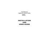
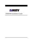
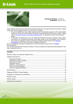
The NBase XM542 Ethernet switch card and the EM541/FO extension module provide Ethernet
switching capabilities and high-speed 100Base-T backbone connectivity for the GigaHUB system.
Based on highly-integrated ASIC technology, coupled with the GigaHUB MatrixBus backplane,
the XM542 has the capability to increase network performance more than tenfold. By offering both
end station and high-speed server/backbone connections, this high performance 10/100Mbps workgroup switch enables a cost-effective deployment of switching technology throughout the enterprise.
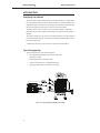
Description
The XM542 occupies one slot of the GigaHUB chassis and features 16 switched 10Base-T
Ethernet ports, as well as the following high-speed extensions:
a.
Internal Fast Ethernet MatrixBus™ connection (Half/Full Duplex)
b. External 10/100 Mbps UTP port (Half/Full Duplex) OR
c.
Slot for EM541/FO, 100Base-FX port module (Half/Full Duplex)
System
Figure 1: General View XM542 in GigaHUB
Features
Versatility
Sixteen switched 10Base-T Ethernet ports, one built-in
10/100 Mbps UTP port
High-Speed Connectivity
Internal Fast Ethernet MatrixBus connection and optional
100Base-FX module
Performance
Wire speed filtering and forwarding rate of 650Kpps
Transmission
Up to 110 km with singlemode 100Base-FX ports
Management
SNMP by MegaVision, NBase’s comprehensive NMS
Port Mirroring
Allows monitoring of switch traffic from any port
1
XM542 for GigaHUB
NBase Communications
APPLICATIONS
Configuring Your Network
The XM542 combines switched 10Mbps Ethernet and Fast Ethernet technology in a seamless integration of regular Ethernet and the IEEE 802.3u 100Base-TX standard. As an essential component of the
GigaHUB™architecture, the XM542 is the ideal workgroup switched solution for bandwidth-hungry
networks requiring high-speed connectivity to local servers and corporate backbones.
The 10Base-T ports can connect directly to end users to provide up to 20Mbps of dedicated Full
Duplex bandwidth. The result is a highly efficient utilization of each segment’s allocated 10Mbps of
bandwidth.
The external 10/100Mbps port can be connected to a local high-performance server, while attachment
to the internal MatrixBus would provide connectivity to the enterprise backbone through the XM59x
Fast Ethernet switching cards.
A 100Base-FX module enables a direct connection to a switched Fast Ethernet backbone.
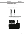
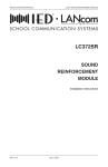
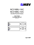
Typical Configurations
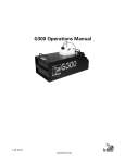
Typical network applications for the XM542 would include:
•
Driving high bandwidth applications where dedicated 10Mbps links
(H/F Duplex) are needed
•
Interlinking Ethernet and Fast Ethernet networks
•
Connection to Fast Ethernet servers in Full/Half Duplex mode
•
Aggregating workgroup traffic to Fast Ethernet switch module
Figure 2: Various application possibilities of the XM542
2
XM542 for GigaHUB
NBase Communications
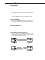
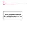
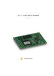
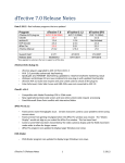
Understanding the Backplane Connections
The XM542 switch operates in the MatrixBus topology of the MegaHUB platform. By connecting to
other MegaHUB cards, the XM542 helps streamline a company’s network. The following cards can
be connected to the XM542 through the MatrixBus backplane:
XM542
Back-to-back connection for switched Ethernet port density
XM59x A variety of applications through attachment to the XM59x family for achieving a high
density of 10/100 connectivity (See Configuring Your Network above)
Figure 3: Two XM542 cards in a back-to-back connection
Figure 4: XM542 connected to XM59x
3
XM542 for GigaHUB
NBase Communications
INSTALLATION and SETUP
Unpacking and Inspection
Upon receiving the XM542, inspect the carton for visible external damage. If the carton is damaged,
request that the carrier’s agent be present during unpacking and do not destroy the shipping carton.
After removing the XM542, examine it for obvious physical damage such as dents or dislodged components. In case of damage, notify the carrier and follow his instructions for damage claims. In addition, inform your NBase representative immediately, providing specific details of the damage. The
representative will arrange for repair or replacement. If necessary, retain the carton and packing material for return shipment.
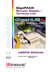
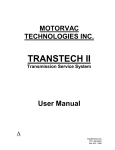
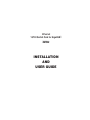
XM542 Front Panel and Card
The XM542 card is illustrated below in Figure 5. The table describes the functions of its various components and LED indications.
Figure 5: Detailed View XM542
4
XM542 for GigaHUB
NBase Communications
XM542 Front Panel and Card
1
Backplane Connector
Connects XM542 to GigaHUB backplane
2
Captive Screw
Secures the XM542 card in the GigaHUB chassis
3
Extractor/Handle
Used for inserting the XM542 card into the GigaHUB chassis
4
Global LEDs
See Installing the XM542 for these two LED indications
5
10Base-T port LEDs
LK
RX
Green ON indicates link connection
Green ON indicates port receive activity
6
10Base-T Ports
Group of 16 RJ-45 switched Ethernet ports for 10Mbps
connection
7
High-speed Port LEDs
As Item 5 above
8
High-speed Port
RJ-45 port for 10/100 Mbps connection
9
Uplink Panel
High-speed interface slot to house 100Base-FX uplink
module (EM541/FO)
10 Uplink Connector
Connects extension module (EM541/FO)
11 Jumpers
Set of 6 jumpers for configuring Ports 17 and 18
Installing the XM542
The XM542 is installed in a single slot of the GigaHUB System and is hot-swappable. Please refer
to Figure 5 during the mounting procedure.
The following tools are required to correctly mount the XM542 switch card:
• 6” flat-tip screwdriver
• 6” Phillips screwdriver
The mounting procedure is as follows:
1. Hold the XM542 by the two extractors/handles and insert it into its allocated slot in the
GigaHUB. Upon reaching the GigaHUB backplane, push the extractors/handles towards
each other to secure the XM542.
2. Tighten the two captive screws on the XM542 panel, and gently push the extractors away
from each other.
3. The self-test diagnostics for the XM542 will run for about one minute.
The RUN and STA LEDs turn ON at Power UP and stay ON for the duration of the
diagnostic cycle. Upon the successful completion of the self-test, the STA LED turns OFF.
If the RUN LED turns OFF but the STA LED is turned ON, the self-test has failed.
During normal operation, RUN ON and STA ON indicates a global error.
Self-test Diagnostics:
RUN
ON
ON
OFF
ON
STA
ON
OFF
ON
ON
Self-test in progress
Normal Mode
Self-test failed
Global Error
4. On the GigaHUB LCD, open the Expanded Card Commands window to verify that the
XM542 appears, indicating that the GigaHUB has identified it.
5
XM542 for GigaHUB
NBase Communications
Network Connections
10Base-T Ports
All ports are external connections over UTP/STP Category 5 or 3 cable (100m max length), through
RJ-45 connectors.
Internal Connection
The internal Fast Ethernet port provides connectivity to the XM59x Fast Ethernet switching modules,
or a back-to-back connection to another XM542 card.
10/100 UTP Port
The external 10/100 UTP port transmits over Category 5 or 3 cables through RJ-45 connectors to
local servers or to other modules such as the LC372 or XM53x.
EM541/FO Extension Module
The optional EM541/FO Extension Module features an external fiber optic port for direct attachment
to high-speed networks. This 100Base-FX connection provides a link distance of up to 2km over multimode fiber through DSC connectors. When installed, the EM541/FO disables the operation of the
built-in 10/100 UTP port.
Connecting the Ethernet Devices
For optimum performance, the Ethernet segments connected to the XM542 must be configured carefully. Generally, the segments should be configured so that machines on a given port communicate
primarily among themselves; i.e. most traffic does not need to cross the switch. However, there are
situations for which this is not the best configuration.
Connecting an Ethernet device to a 10Base-T or 100Base-TX port
The 10Base-T and 100Base-TX ports on the XM542 are designed to be connected directly to a hub,
using a standard straight-through patch cable. In order to connect a workstation to the switch, either
there must be a hub between them or a crossover cable must be used.
Figure 6: Straight cable connection between an XM542 and a hub
Figure 7: Crossover cable connection between an XM542 and a server/PC
6
XM542 for GigaHUB
NBase Communications
Port Configurations
Each 10Base-T port can be configured in Half Duplex mode for shared networks, or as a dedicated
Full Duplex link running at up to 20Mbps. Ports can also be configured for auto polarity detection and
correction. Front panel LEDs display each port’s link and receive status.
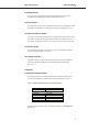
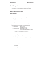
Default Configuration
The XM542 is shipped from the factory in the following configuration:
10Base-T ports
10/100Base port
MatrixBus™ connection
10, half duplex
100, half duplex
100, full duplex
Jumpers
Ports 17 and 18 must be configured through jumpers to determine the duplex mode, the rate and autonegotiation. The settings depend upon whether the ports are used as 10Mbps or 100Mbps conncetions.
Jumpers 1 -3 control Port 18, which is an external connection. Jumpers 4-6 control Port 17, which is a
backplane connection.
The default configuration at Power Up is: J1 is closed, all the other jumpers are open. In order to
make changes, remove the XM542 card from the GigaHUB chassis, reconfigure and then reinstall.
Port 17
Port 18
Jumper
Open/Closed
Duplex
J4
Open
Closed
Full
Half
J5
Open
Closed
J6
Open
Closed
J1
Open
Closed
J2
Open
Closed
J3
Open
Closed
Rate
Auto Neg
Type of Port
10/100Mbps
10/100Mbps
100Mbps
10Mbps
100Mbps
100Mbps
Enabled
Disabled
Full
Half
100Mbps
100Mbps
10/100Mbps
10/100Mbps
100Mbps
10Mbps
10/100Mbps
10/100Mbps
Enabled
Disabled
10/100Mbps
10/100Mbps
7
XM542 for GigaHUB
NBase Communications
THE XM542 and NETWORK MANAGEMENT SYSTEMS
The XM542 card complies fully with GigaHUB’s management architecture for local or remote access
and downloading of firmware updates, enabling the SNMP Manager (InterView NMS) to perform all
the management functions provided by the GigaHUB. Front panel LEDs display current status for
simplified installation and maintenance.
The XM542 can also be managed locally via the GigaHUB’s LCD. Details are provided in GigaHUB
Management.
GigaHUB Management
The operational status of the XM542 can be monitored on the card’s front panel LEDs and on the
GigaHUB LCD. See Installing the XM542 for details of card status LEDs, and Front Panel for details
of port status LEDs.
GigaHUB LCD
Card Status/Commands Window
This window is used for comprehensive XM542 monitoring. Access to it is described in the GigaHUB
User’s Manual, Part B, Extended System Manager, Section 5.4.
The status parameters of the XM542 are described in the window as the curser is moved across the
LEDs. The description for a LED is true if the LED (circle) is filled black; otherwise, the complementary possibility is true. The descriptions are summarized in Table 1 below, which shows the LEDs,
Channels and LED functions.
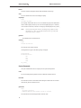
Table 1: XM542 Status using GigaHUB Card/Stat/Cmds Window LEDs
GigaHUB Card Status/Commands Window LEDs
Giga
HUB
1
2
3
4
5
6
7
8
9
10
11
12 15
P1
LINK
OK
P4
LINK
OK
P7
LINK
OK
P 10
LINK
OK
P 13
LINK
OK
P 16
LINK
OK
P 17
LINK
OK
P1
Detach
P1
FDplx
Spare
P2
Detach
P2
FDplx
Spare
P3
FDplx
Spare
P4
FDplx
Spare
P5
Detach
P5
FDplx
Spare
P6
Detach
P6
FDplx
Spare
P7
Detach
P7
FDplx
Spare
P8
Detach
P8
FDplx
Spare
P9
Detach
P9
FDplx
Spare
P 10
Detach
P 10
FDplx
Spare
P 11
Detach
P 11
FDplx
Spare
P 12
Detach
P 12
FDplx
Spare
P 13
Detach
P 13
FDplx
Spare
P 14
Detach
P 14
FDplx
Spare
P 15
Detach
P 15
FDplx
Spare
P 16
Detach
P 16
FDplx
Spare
Spare
Spare
Spare
P3
LINK
OK
P6
LINK
OK
P9
LINK
OK
P 12
LINK
OK
P 15
LINK
OK
Spare
P3
Detach
P4
Detach
P2
LINK
OK
P5
LINK
OK
P8
LINK
OK
P 11
LINK
OK
P 14
LINK
OK
Spare
Spare
Spare
Spare
P 17
Detach
P 17
FDplx
P 17
Speed
P 18
LINK
OK
P 18
Detach
P 18
FDplx
P 18
Speed
MOP
MOP
Module
Enable
Spare
Chan.
1
2
3
4
5
6
7
8
XM542 for GigaHUB
NBase Communications
Cards Status Window
This window provides general status information about the XM542. Details are provided in
the GigaHUB User’s Manual, Part B, Extended System Manager, Section 5.5.3.
Cards Type Window
This window shows the type of LAN Card identified for each LAN Card in a GigaHUB slot. Details
are provided in the GigaHUB User’s Manual, Part B, Extended System Manager, Section 5.2.1.1.
Serial Buses Per Resource Window
This window is used to attach XM542 cards housed in a GigaHUB to Eth100SW resources. Details
are provided in the GigaHUB User’s Manual, Part B, Extended System Manager, Section 5.2.1.3.2.
The procedure for attaching an XM542 to any one or more of the resources is also described there.
Card Versions Window
This window shows the XM542 version. Details are provided in the GigaHUB User’s Manual,
Part B, Extended System Manager, Section 5.2.1.2.
Slots Assignment Window
This window is used to view all the resources allocated to all the LAN Cards in the GigaHUB.
Details are provided in the GigaHUB User’s Manual, Part B, Extended System Manager,
Section 5.2.1.3.3.
Commands
Expanded Card Commands Window
The following commands are invocable in the Expanded Card Commands window (described
generically in the GigaHUB User’s Manual, Part B, Extended System Manager, Section 5.3):
Table 2: Expanded Card Commands Window Commands/Parameters
Command
Parameters
Reset Card
Global FDplx
Module Enable
Attach port
Detach Port
Set Full Duplex
Set Half Duplex
Cold, Warm, Factory Default
Full, Half
Enable, Disable
P # (Ports 1 to 18)
P # (Ports 1 to 18)
P # (Ports 1 to 16)
P # (Ports 1 to 16)
The Duplex mode for Channels 17 and 18 is configured through jumpers. See Installation and
Setup, Jumpers.
9
XM542 for GigaHUB
NBase Communications
Console Management
This section describes how to use the console services to configure and manage the XM542.
You access the console by connecting a terminal to the GigaHUB RS-232 DB-9 connector.
Setting Up and Starting the Local Console
System Requirements
Hardware Requirements
• XM542 card
• Either a VT100 terminal or a VT100 terminal emulator running on a workstation or PC
• Straight-through RS-232 cable with a 9-pin male D-subminiature connector on one end
and an appropriate connector on the other end to attach to the VT terminal or VT100
terminal emulator.
Software Requirements
If you are using a workstation, use the VT100 terminal emulation software appropriate for
your workstation.
If you are using a PC to emulate a VT100 terminal, you can use the following software:
• In a DOS environment:
- MS-DOS 3.30 or later
- PROCOMM PLUS for DOS
• In a Windows environment:
- Microsoft Windows 3.1 or later
- Windows Terminal or PROCOMM PLUS for Windows
NOTE
Because of their compatibility and reliability, the software combination listed above are
recommended. Other applications may also provide satisfactory results.
VT100 Terminal Settings
Use the following modem settings when connecting the VT100 terminal or terminal emulator to the
XM542 (via the GigaHUB).
• Press the Setup key (usually identified on the screen’s prompt bar) and set the parameter
values as follows:
General Setup
- VT100 Mode
- Application Keypad
Communications Setup
- Transmit = 9600 (baud)
- Receive = Transmit
- 8 Bits, No Parity
- No Local Echo
• Terminate the setup session by keying Ctrl-C
10
XM542 for GigaHUB
NBase Communications
CLI Access
The GigaHUB ESM allows access to the CLI facility of a card in the GigaHUB. It routes CLI commands from the host (eg. VT100 terminal), via the GigaHUB Management Bus, to the addressed card
for decoding/emulation, and drives the card responses to the Management Bus. The CLI commands
and responses are encapsulated in a Data Link Layer (DLL) frame format.
To start the local console, follow the steps below:
• Connect a VT100 terminal or a VT100 terminal emulator to the Outband DB9 connector on
the GigaHUB using a straight-through RS-232 cable.
• Make sure both units are powered on.
• To establish connection to the CLI as well as to display the GigaHUB CLI Main Menu
for the XM542:
For
Press
VT100 terminal
PC VT100 Terminal Emulator
Procomm
BREAK key
CTRL-BREAK key
ALT-F7 keys
In response to pressing the BREAK key, the CLI Main Menu window will display a list of cards
having CLIs (eg. XM542). To select a card, move the cursor to the row and press ENTER twice.
When the command line appears, you can enter the console commands.
To return to the CLI Main Menu from any other window, press CTRL-C keys.
NOTE
The next section gives the definitions and syntax for the command-line commands. Use the online
HELP for more information about parameters you can use with the commands and to see
examples of queries using the commands.
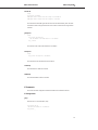
Console Commands
The console commands contain a set of commands which allow the user to configure the
Administrative Interface parameters and user interface.
?
Typing ? at the Administrative Interface prompt displays a list of all the available command topics
and a short explanation about each. Typing in one of the names on this list will yield a list of the commands under that topic.
SYS_console> ?
Commands groups are:
----------------------console
Console related commands
system
System related commands
ip
IP related commands
port-cfg
Port configuration-related commands
SYS_console>_
help-kbd
This command lists the console function keys.
SYS_console>
?
!
SYS_console>
help-kbd
for a list of the categories
for previous command
_
11
XM542 for GigaHUB
NBase Communications
banner
The banner command will display the XM542 NBase Administrative Interface logo.
clear
The clear command will clear the screen and display the prompt.
set-prompt
Usage:
set-prompt <new_prompt>
The set-prompt command allows the user to set a new command line prompt for the Administrative
Interface. With the prompt command, you can set a more meaningful prompt (up to 15 characters),
such as a location of the switch, or the name of a work-group. The default prompt is SYS_console> _
NOTE
If the new prompt is longer than 15 characters, the following message is displayed: “prompt
string too long <xx>”, where <xx> is the number of characters that were given. The prompt
will proceed to use the first 15 characters.
get-baud
This command shows the serial line baud rate.
set-baud
Usage:
set-baud <new baud rate>
This command sets the serial line baud rate.
If an illegal baud rate is typed in, the following message is displayed:
Illegal baud rate
Allowed baud rates are:
4800
9600
19200
38400
SYS_console>_
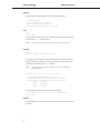
System Commands
The System Commands allow the user to display and set the system related parameters.
reset
The reset command updates the parameters stored in NVRAM and reinitializes the device.
init-nvram
This command resets the non-volatile RAM on the SNMP Agent to default values. The command
takes effect only after the switch has been reset.
get-rsw-file
Usage:
SYS_console> get-rsw-file
NVRAM-based SNMP Agent remote software file name is: <filename>
This command retrieves the SNMP Agent Software remote file name.
12
NBase Communications
XM542 for GigaHUB
set-rsw-file
Usage:
set-rsw-file <filename>
SNMP Agent remote software file name change in the NVRAM OK.
SNMP Agent remote software file name changed to <filename>
This command sets the SNMP Agent Software remote file name downloaded by TFTP. This name
must match the name of the agent software file on the TFTP server and must not be longer than 80
characters.
get-tftp-srvr
Usage:
SYS_console> get-tftp-srvr
The IP address of the TFTP server is: <IP address>
SYS_ console>
This command retrieves the TFTP download server IP address.
set-tftp-srvr
Usage:
SYS_console> set-tftp-srvr <IP address>
This command sets the TFTP download server IP address.
enable-tftp
This command forces TFTP in the next boot.
disable-tftp
This command disables TFTP in the next boot.
IP Commands
This section lists the IP Configuration commands available to the command line interface.
IP Configuration
get-ip
Shows the device’s current IP address, if any.
SYS_console> get-ip
The device IP address is: <IP address>
SYS_console> _
13
XM542 for GigaHUB
NBase Communications
get-ip-conf
Shows the complete current IP configuration - address, network mask and gateway.
SYS_console>
The device
The device
The device
get-ip-conf
IP address is: <IP address>
netmask address is: <IP netmask>
default gateway IP address is: <IP gateway>
set-ip
Usage:
set-ip <IP address>
Sets the IP address of the SNMP Agent. The new value will only be stored in the NVRAM, and the
user must execute a <reset> to effect the change.
NOTE
The default gateway address and the IP address of the switch must be in the same subnet.
set-ip-conf
Usage:
set-ip-conf <IPaddress> <netmask> <default gateway>
Sets IP address and network IP address. If a previous IP configuration was being used, the new configuration will be saved in NVRAM for the next session. In order to use the newly defined values
immediately, reset the system using the <reset> command.
NOTE
If the IP configuration is not specified, the agent will not respond to any in-band requests,
including ping messages.
SYS_console> set-ip-conf 194.1.1.1 255.255.255.000 194.1.1.2
Device IP Address and Mask unchanged for this session
Device IP Address, mask and default gateway change in the NVRAM OK
After boot the device IP address, Mask and default gateway will be:
IP address
: <IP address>
IP netmask
: <IP netmask>
IP gateway
: <IP gateway>
If the wrong gateway is typed in, the following message will be displayed:
The network part of the IP address must be equal to the default gateway
network part.
get-gatew
Shows default gateway. This command shows which default route will be used to access a different
IP network.
14
NBase Communications
XM542 for GigaHUB
set-gatew
Usage:
set-gatew <IP address>
Sets the default gateway IP Address. This command lets you specify the address of the router used to
access a different IP network. The default value for the default gateway IP address is 194.1.1.2. This
command takes effect after reset.
NOTE
The default gateway address and the IP address of the switch must be in the same subnet.
SYS_console> set-gatew <IP gateway address>
Device Default Gateway change in the NVRAM OK
Device Default Gateway changed to : <IP gateway address>
SYS_console> get-gatew
Device default gateway address is : <IP gateway address>
SYS_console> _
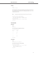
Port Commands
get-port-cfg
Usage:
get-port-cfg
This command displays the configuration of all the ports.
SYS_console> get-port-cfg
Port_ID
1
2
..
..
..
16
FDPLX
OFF
ON
..
..
..
OFF
SYS_console>
set-port-dplex
Usage:
set-port-dplex <port No> {half | full}
This command sets the port mode to half or full duplex.
SYS_console> set-port-dplex ?
set-port-dplex sets the port mode: half or full duplex
[arg #0] port number 1....16
[arg #1] enter either {half | full}
SYS_console>
15
XM542 for GigaHUB
NBase Communications
TROUBLESHOOTING
The XM542 is highly reliable. If you encounter an operating problem, follow the troubleshooting
steps below. If the problem persists, contact your local NBase representative.
1.
Review all link LEDs to ensure that those ports you believe should be functioning are properly
attached to a cable.
2.
Verify that your cables are wired correctly; i.e. use a UTP crossover cable to directly connect
another switch or any other DTE type-device (such as a workstation) directly to a port.
(See Network Connections)
3.
Review all link LEDs to ensure that those ports you believe should be functioning are
properly configured, and not disabled or partitioned.
Problem: LINK LED is ON but data is not being forwarded through switch.
Cause:
Cables are too long.
Solution: Make sure that cables are as defined in the installation section of this guide. Check that
cables meet the 10Base-T/100Base-TX standards and that they do not exceed 100m.
Problem: Port disabled due to a defective device on segment.
Cause:
When a defective NIC card causes a permanent jam on the network, the port will be
disabled by the XM542.
Solution: a) Locate the defective device and disconnect it from the network.
b) In a managed unit the disabled port can be enabled through management or by shutting
off the unit and powering up again.
c) In an unmanaged unit, the disabled port can be enabled only by shutting off the unit and
powering up again.
Problem: Port 18 functions as a 100Base-TX port but stops functioning when the optical
module is installed, ie Port 18 does not function as an optical port.
Cause:
Optical module is defective.
Solution: Replace the optical module.
Problem: There is a failure during self-test.
Cause:
The XM542 card may not be securely installed in its slot.
Solution: Re-insert the XM542 card into its GigaHUB slot, making sure that it is secure,
and activate a RESET.
If you encounter any situations you cannot solve, obtain, if possible, the following information:
•
The serial number of your switch and its hardware address
•
If the NMS option is installed, the firmware revision number displayed in the terminal console
banner message
•
The configuration of the equipment being interfaced with the switch
•
The sequence of events leading up to your problem
•
Troubleshooting procedures you have already followed
After compiling the above information, contact your local NBase representative or a Customer Service
Representative. In addition, if you have specific questions about your network configuration, or have a
particularly difficult network, please call our technical support.
Tel: (972) 4-993-6200, 4-993-6271, 4-993-6257 or 4-993-6269
Fax: (972) 4 989-2743
E-mail: [email protected]
16
XM542 for GigaHUB
NBase Communications
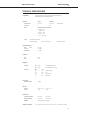
TECHNICAL SPECIFICATIONS
Compatibility
EEE 802.3; IEEE802.1D; IEEE 802.3u (Fast Ethernet); MIB II (RFC 1213);
Ethernet MIB (RFC1643); Bridge MIB (RFC1493)
Electrical
XM542
EM541/FO
Voltage/Current
5V DC / 6A
5V DC / 0.4A
Power Units
4
0.27
Pinout
SUTP RJ-45 Connector (on XM542)
(from GigaHUB)
1 - Transmit (TX+)
2 - Transmit (TX-)
3 - Receive (RX+)
6 - Receive (RX-)
4, 5, 6, 7 are Unused
Cables
Twisted-Pair cable for station
UTP/STP Category 5
100m / 330 ft max length
Male RJ-45 connectors
Optical (EM541/FO)
Fiber
MM
Tx Power
Rx Sensitivity
62.5 / 125
-18.5 dBm
-31.5 dBm
Connectors
STP
Fiber
RJ-45
DSC
Diagnostics
Port LEDs
Global LEDs
LK
Green
ON indicates link connection
RX
Green
ON indicates port receive activity
RUN
ON
ON
OFF
ON
STA
ON
OFF
ON
ON
Self-test in progress
OK
Self-test failed
Global error
Performance
Filter/Forward Rate
650Kpps
Physical
HxWxD
Weight
30 x 27.7 x 3.5 cm
<1 kg
11.8” x 11” x 1.4”
<2.2 lb
0°C to 40°C
-10°C to 50°C
32°F to 104°F
14°F to 122°F
Environment
Operating Temperature
Storage Temperature
Humidity
Standards Compliance
85% maximum, non-condensing
UL-1950; CSA 22.2 No 950; VCCI; FCC Part 15 Class A; CE - 89/336/EEC, 73/23/EEC
17