1
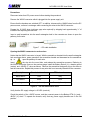
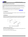
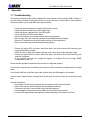
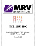
NC316BU-1AC NC316BU-1DC One-Slot Powered Chassis User Guide Installation Manual Revision B1 April 2007 NC316BU-1AC/DC User Guide Table of Contents 1 2 3 4 5 6 7 Preliminary Considerations ........................................................................................................iii 1.1 Trademarks ............................................................................................................................................iii 1.2 Copyright................................................................................................................................................iii 1.3 Customer Support..................................................................................................................................iii 1.4 MRV Regulatory Compliance.................................................................................................................iv 1.5 General Safety Requirements................................................................................................................ v 1.5.1 Laser Safety....................................................................................................................................... v 1.5.2 Static Electricity .................................................................................................................................vi 1.5.3 Workplace Preparation ......................................................................................................................vi 1.6 Specific Document Information .............................................................................................................vii 1.7 Latest Revision and Related Documents..............................................................................................vii Fiber Driver Chassis Introduction ...............................................................................................1 Unpacking the NC316BU Chassis ...............................................................................................2 Fiber Driver Power Supplies ........................................................................................................3 4.1 4.2 Safety with Power Sources .................................................................................................................... 3 Power Supply Maintenance ................................................................................................................... 3 Mounting Options and Accessories............................................................................................6 5.1 5.2 5.3 Table Mount ........................................................................................................................................... 6 Wall Mount ............................................................................................................................................. 6 Other Chassis Accessories.................................................................................................................... 6 Module Installation .......................................................................................................................7 Appendix .......................................................................................................................................8 7.1 7.2 Troubleshooting ..................................................................................................................................... 8 Technical Specifications ........................................................................................................................ 9 P/N 1200192-001, Rev B1 i NC316BU-1AC/DC User Guide List of Figures Figure 1 -- Fiber Driver chassis ............................................................................................................................. 1 Figure 2 -- NC316BU-1AC front panel .................................................................................................................. 1 Figure 3 -- NC316BU-1DC front panel .................................................................................................................. 1 Figure 4 – Unpacking the chassis ......................................................................................................................... 2 Figure 5 – DC WAGO connector........................................................................................................................... 4 Figure 6 -- Braided DC power harness ................................................................................................................. 4 Figure 7 – DC cable installation ............................................................................................................................ 5 Figure 8 -- DC wire harness wire colors................................................................................................................ 5 Figure 9 -- Wall mount bracket NC316MB-1 ......................................................................................................... 6 Figure 10 – Align edges of the module to the chassis slot rails .............................................................................. 7 Figure 11 -- Chassis dimensions and weights ........................................................................................................ 9 Figure 12 – Power supply technical specifications ............................................................................................... 10 P/N 1200192-001, Rev B1 ii NC316BU-1AC/DC User Guide 1 Preliminary Considerations 1.1 Trademarks All trademarks are the property of their respective holders. 1.2 Copyright MRV Communications reserves the right to make changes to technical specifications and documentation without notice in order to improve reliability, function, or design. The user assumes sole responsibility for applying the information supplied herin. Copyright © 2007 by MRV Communications, Inc. All rights reserved. 1.3 Customer Support Before contacting customer support, look for software updates, technical specifications, and frequently asked questions (FAQ) online at the MRV support website: http://service.mrv.com. The website includes information regarding software updates, technical specifications, frequently asked questions (FAQ), and contact information. Contact help online by sending email to [email protected] or through the website request link at http://service.mrv.com/support/forms/supportcall.cfm. For direct MRV customer support by telephone, call your local sales representative, system engineer, or one of the following numbers. +1-800-435-7997 MRV Americas (US, Canada, and Latin America) +1-978-952-4888 MRV Europe +49-6105-2070 MRV International +972-4-993-6200 Include the following important information when opening a support case. • • • • • • • • Site ID or company name Contact information Model or product name Serial number Top assembly revision (see label on device) Brief problem or question including a description of the host network environment Attenuation data for applicable high-speed fiber links Urgency of the issue P/N 1200192-001, Rev B1 iii NC316BU-1AC/DC User Guide 1.4 MRV Regulatory Compliance Contact your sales representative for more regulatory compliance information regarding specific MRV products or product families. Fiber Driver Chassis Compliance: FCC Part 15 (Class A); IC (Class A); EMC Directive: Emission (Class A) and Immunity; LVD Directive: Electrical Safety; CE Marking; TUV CUE Mark (Canada, USA, EU); GOST; RoHS Directive, WEEE Directive: Wheelie Bin Mark; ETSI, NEBS, C-Tick Fiber Driver Modules Compliance: FCC Part 15 (Class A); IC (Class A); EMC Directive: Emission (Class A) and Immunity; LVD Directive: Electrical Safety; RoHS Directive, WEEE Directive: Wheelie Bin Mark; ETSI Optical and Copper Transceivers Compliance: FCC Part 15 (Class A); IC (Class A); EMC Directive: Emission (Class A) and Immunity; LVD Directive: Electrical Safety; CE Marking; TUV; UL, CSA, RoHS Directive, ETSI, NEBS, compliant with EN 60825-1/A1:2002 Safety of Laser Products P/N 1200192-001, Rev B1 iv NC316BU-1AC/DC User Guide 1.5 General Safety Requirements Disconnect all power from electronic devices before servicing. Some equipment may have multiple power cords requiring disconnection. 1.5.1 Laser Safety WARNING: Fiber optic equipment may emit laser or infrared light that can injure your eyes. Never look into an optical fiber or connector port. Always assume that fiber optic cables are connected to a laser light source. CAUTION: Do not install or terminate fibers when a laser may be active. WARNING: Never look directly into a live optical fiber. Always wear appropriate laser safety glasses when working with open fiber cables that might be connected to an operational laser transmitter. Direct open fibers ends away from faces. CAUTION: Use of controls or adjustments or performing procedures specified herein may result in hazardous radiation exposure. other than those If a fiber optic laser device output is recognized as a higher than Class 1 product (Class 1M, for example), the device is evaluated, labeled, and certified by TUV. Class 1 and 1M outputs are not considered hazardous, but laser safety practices should always be observed. A fiber optic transceiver emits either single-mode or multi-mode light into a fiber optic strand. Take the following precautions when handling optical fibers. • • • • • • • Wear safety glasses when you install optical fibers. Be aware of the risk of laser radiation exposure. Because transmitted light is invisible to the human eye, always assume that a fiber optic transceiver is on and operational. Never look directly into a beam (TX part of a transmitter) or open fiber ends. The invisible light can damage your eyes. Place optical fibers in a safe location during installation. Protect optical fiber connectors with clean dust caps for safety and cleanliness. Follow the manufacturer instructions when using optical test equipment. P/N 1200192-001, Rev B1 v NC316BU-1AC/DC User Guide 1.5.2 Static Electricity Eliminate static electricity in the workplace by grounding operators, equipment, and devices including components and computer boards. Grounding prevents static charge buildup and electrostatic potential differences. Transporting products in special electrostatic shielding packages reduces electrical field damage potential. 1.5.3 Workplace Preparation A safe and effective workplace provides the following items. • ESD protective clothing/smocks: Street clothing must not come in contact with components or computer boards since the various materials in clothing can generate high static charges. ESD protective smocks, manufactured with conductive fibers, are recommended. • Electrostatic shielding containers or totes: These containers (bags, boxes, etc.) are made of specially formulated materials, which protect sensitive devices during transport and storage. • Antistatic or dissipative carriers: These provide ESD protection during component movement in the manufacturing process. It must be noted that antistatic materials alone will not provide complete protection. They must be used in conjunction with other methods such as totes or electrostatic shielding bags. • Dissipative tablemat: The mat should provide a controlled discharge of static voltages and must be grounded. The surface resistance is designed such that sliding a computer board or component across its surface will not generate more than 100 V. • Operator grounding: Keep a wrist strap or ESD cuff in constant contact with bare skin with a cable for attaching it to the ESD ground. The wrist strap drains off the static charge of the operator. The wrist strap cord has a current-limiting resistor for personnel safety. Wrist straps must be tested frequently to ensure that they are undamaged and operating correctly. Use special grounding heel straps or shoes when a wrist strap is impractical. These items are effective only when used in conjunction with a dissipative floor. • ESD protective floor or mat: The mat must be grounded through a current-limiting resistor. The floor or mat dissipates the static charge of personnel approaching the workbench. Special conductive tile or floor treatment can be used when mats are not practical or cause a safety hazard. Chairs should be conductive or grounded to the floor with a drag chain. P/N 1200192-001, Rev B1 vi NC316BU-1AC/DC User Guide 1.6 Specific Document Information Document Number: PN 1200192-001 Rev B1 Document: NC316BU-1/xx User Manual and Installation Guide Release Date: April 2007 1.7 Latest Revision and Related Documents The latest revision of MRV documents may be found at: http://www.mrv.com. Release Notes for Fiber Driver modules are produced as required. Fiber Driver modules are shipped with relevant documents and manuals. Refer to the documents accompanying the Fiber Driver device or to the website listed above before contacting customer support. MegaVision User Manual: Describes management of Fiber Driver modules and other MRV Communications SNMP manageable products using MRV Communication’s MegaVision® Pro® Network Management System. P/N 1200192-001, Rev B1 vii NC316BU-1AC/DC User Guide 2 Fiber Driver Chassis Introduction The NC316BU chassis is the foundation for the Fiber Driver® media module product line. Fiber Driver® chassis models are available with 1, 2, 3, 4, or 16 slots for configuration flexibility in every environment. Figure 1 -- Fiber Driver chassis A Fiber Driver chassis slot may host one of the many MRV Fiber Driver® media modules. A few fiber driver modules require two adjacent slots. Only the two-slot and sixteen-slot chassis accommodate these two-slot devices because of their physical configuration. Other Fiber Driver chassis accommodate only single-slot modules. The one-slot and two-slot chassis are available with either an AC or a DC power supply built into the unit. These chassis may be installed on a flat surface or wall-mounted. This manual focuses on the single slot chassis only. Refer to the technical specifications table for dimensions of the device. Figure 2 -- NC316BU-1AC front panel Figure 3 -- NC316BU-1DC front panel P/N 1200192-001, Rev B1 1 NC316BU-1AC/DC User Guide 3 Unpacking the NC316BU Chassis For unpacking, refer to the steps and the figure below. Step 1 Open the cardboard box. Step 2 Carefully remove contents from the box. Step 3 Remove the bag from the chassis. Step 4 Remove all product contents the packaging. NC316BU-1AC Chassis unit with AC power supply User Guide document AC power cord NC316BU-1AC Chassis unit with DC power supply User Guide document DC connector (attached to chassis) In the unlikely event that a part is missing, contact your authorized dealer or representative. If it becomes necessary to return the product, repackage the entire contents in the original container materials. Figure 4 – Unpacking the chassis Packaging materials may differ somewhat between chassis models. P/N 1200192-001, Rev B1 2 NC316BU-1AC/DC User Guide 4 Fiber Driver Power Supplies Fiber Driver® chassis with one and two slots (NC316BU-1 and NC316BU-2) include an integrated AC or DC power supply. No additional power supply option is available for these models. Most Fiber Driver power supplies are auto ranging with no manual configuration available. Refer to the technical specifications table in the appendix for data regarding specific models. 4.1 Safety with Power Sources Use caution when working with power supplies and live power sources. When equipped with an external power switch, set the switch to the off position while connecting or disconnecting a power source. If a grounding terminal is supplied, use a properly rated conductor (wire) to connect to an industry approved grounding source near the unit. The length of the ground conductor as well as the wire size and composition are important for proper grounding. Electronic equipment should use protected source power circuits. Provide a listed circuit breaker suitable for protecting branch circuit wiring rated at 60 volts DC minimum. Disconnect all relevant power cables before installing or removing a power supply from a chassis. Some safety guidelines are listed in the front of this manual. There are many other safety concerns while working with electronic equipment. Become familiar with your environment, and observe all vendor and industry recommendations. 4.2 Power Supply Maintenance Fiber Driver chassis include AC and DC power supplies in sizes and ratings to match each chassis. They do not interchange between chassis. Operate all electrical equipment as intended and described in accompanying documentation to maintain any warranties of the provider and to protect all equipment from electrical damage. The power supplies are designed to operate without manual maintenance. If a power supply from MRV fails to function properly, contact the nearest MRV sales office or MRV customer support to determine the best solution. The operational environment could affect the operation and life of a power supply. Maintain clearance around the chassis to avoid equipment overheating and possible damage. P/N 1200192-001, Rev B1 3 NC316BU-1AC/DC User Guide WAGO Connector Connecting DC power involves connecting three wires to the “WAGO” connector that is furnished with the DC power supplies. Figure 5 – DC WAGO connector DC Connector • Use size 18AWG or larger that comply with UL1061 or equivalent specifications. • Securely connect the Chassis Ground wire to a quality earth ground with approved grounding connection hardware. • Weave the three supply wires into a braid for electronic noise reduction. Figure 6 -- Braided DC power harness P/N 1200192-001, Rev B1 4 NC316BU-1AC/DC User Guide Precautions Disconnect wires from DC power source before starting the procedure! Remove the WAGO connector which is plugged into the power supply unit. Ensure that the breakers are switched OFF. In addition, disconnect the 18AWG wires from the DC power source, so there is no danger while connecting the wires to the WAGO connector Prepare the 18 AWG wires (minimum gage wire required) by stripping back approximately ¼” of insulation and exposing the bare wire. Insert a small screwdriver into the small rectangular hole in the connector as shown to open the pathway for the wire. Figure 7 – DC cable installation Opening the WAGO connector to receive wires Notice that the WAGO connector is keyed. With the screwdriver inserted into the small rectangular hole as shown above, press upward on the screwdriver handle and downward on the screwdriver tip to open the pathway for each wire. Insert the wire into the round hole, and release the screwdriver pressure. Referring to the WAGO connector figure on the previous page, install the Battery Return (L+), chassis ground (center), and –48VDC (L-) wires as shown. Remove the screwdriver and gently tug on the wires to test the connection. Repeat this process for any wire that is not securely fastened to the connector. Description Standard wire colors ETSI wire colors Minus side L- Red Gray Plus side L+ White Blue Chassis ground Green / yellow stripe Green / yellow stripe Figure 8 -- DC wire harness wire colors Verify that the DC supply voltage is -48 VDC (nominal). Check the polarity of the -48VDC source, and then connect power to the Battery RTN (L+) and – 48VDC (L-) wires. To operate the chassis, verify that any power supply breakers are in the ON position. P/N 1200192-001, Rev B1 5 NC316BU-1AC/DC User Guide 5 Mounting Options and Accessories Fiber Driver® chassis models offer different mounting options including table top, wall mounting, and two varieties of rack mounting. Choose the best mounting option for your specific Fiber Driver® chassis model installation and environment. The one-slot and two-slot chassis do not offer rack mount options. Fiber Driver powered chassis require clear air flow around the external chassis vents. Maintain at least an inch of clearance from the vents to allow sufficient cooling for the unit. For the latest ordering information and options, refer to the MRV website: http://www.mrv.com. 5.1 Table Mount One-slot and two-slot Fiber Driver® chassis are designed to operate on a flat and secure surface. All Fiber Driver® chassis offer this option. 5.2 Wall Mount The smallest Fiber Driver chassis (one-slot and two-slot) may be mounted on a wall. The optional bracket for wall mounting is not included with the chassis. Order the bracket (NC316MB-1 or NC316MB-2) specifically if wall mounting is the best option for the chassis in your environment. Figure 9 -- Wall mount bracket NC316MB-1 5.3 Other Chassis Accessories When a module is not installed, an open chassis slot must remain covered during operation. Extra blank panels are available through MRV sales. DC power cables may also be ordered through MRV sales. P/N 1200192-001, Rev B1 6 NC316BU-1AC/DC User Guide 6 Module Installation Take appropriate precautions against electrostatic discharge (ESD). Refer to the front of this manual for some guidelines. Tools • 6-inch Phillips #1 screwdriver (for the module screws) • 6-inch flat-tip screwdriver Instructions: Step 1 If a Blank Panel is covering the target slot, remove it by unfastening the screws with a 6-inch Phillips screwdriver. Either a panel or a module should always cover chassis slots. Open chassis slots violate EMC specifications and impair optimized cooling. Step 2 Align the edge of the card with the rail of the chassis, and slide the module entirely into the slot. Firmly seat the module into the receiving connector with even pressure. Tighten the thumbscrew by hand to secure the module in the chassis. Figure 10 – Align edges of the module to the chassis slot rails Avoid damaging any components by handling the module on the edges only. Use your thumb to push it securely inside the chassis. Do not use excessive force, but make sure the module is fully inserted in the chassis. P/N 1200192-001, Rev B1 7 NC316BU-1AC/DC User Guide 7 Appendix 7.1 Troubleshooting This section provides a basic guide to address the most common issues with NC316BU Chassis. If the information provided in this manual does not resolve the issue, contact MRV Communications customer support or your local MRV sales representative. • • • • • • • • Verify that expected power is supplied by the power source. Verify that power reaches the power supply input. Verify that power switches are in the ON position. Verify operation of LED indicator lights. Ensure all modules are inserted correctly and receiving power. Ensure User Links are functioning properly and sending the desired signal. Ensure DIP switches are set to the proper settings for your application. Ensure all chassis are powered and operating properly. • Review all status LEDs to ensure that those ports you believe should be functioning are properly attached to a cable. • Verify the correct fiber optic cables are being used. Verify multi-mode and single-mode. • Review all status LEDs to ensure that those ports you believe should be functioning are properly configured. • If the suspect ports are not configured properly, re-configure the port through SNMP management or the CLI. Ensure that the equipment attached to this module is configured properly. Verify that the output power of the fiber optic port(s) is within manufacturer’s specification for output power. Verify that the dB loss of the fiber optic cable used is within the dB budget for this module. In most cases, chassis failure is caused by a power fault. Check the power source and input path first. General Precautions • Avoid work on Fiber Driver products and connections during electrical storms. • Fiber Driver service should be performed by qualified personnel. • Disconnect all power sources before servicing the equipment. • Hot-swappable components may be added or removed with active power. • Comply with regional laws and regulations when disposing of all electronic devices. P/N 1200192-001, Rev B1 Appendix - 8 NC316BU-1AC/DC User Guide 7.2 Technical Specifications Chassis Specifications Chassis Model Physical Dimensions [mm] (high x wide x deep) Weight [kg] NC316BU-1/AC 38 x 159 x 199 1.0 NC316BU-1/DC 38 x 159 x 199 1.0 NC316BU-2/AC 65 x 159 x 197 1.4 NC316BU-2/DC 65 x 159 x 197 1.4 NC316BU-3/AC 44 x 439 x 203 3.0 NC316BU-3/DC 44 x 439 x 203 3.1 NC316BU-4S/AC 44 x 439 x 305 4.5 NC316BU-4S/DC 44 x 439 x 305 4.5 NC316BU-16/AC 110 x 439 x 408 8.8 NC316BU-16/DC 110 x 439 x 408 8.7 NC316BU-16T/DC 132 x 541 x 254 8.2 Figure 11 -- Chassis dimensions and weights P/N 1200192-001, Rev B1 Appendix - 9 NC316BU-1AC/DC User Guide Power Supply Specifications Nominal Input Range (VAC at 50/60 Hz) Input Range (VDC) Maximum Rating [Amps] NC316BU-1AC 100 – 240 - 0.3 0 to +50 -20 to +70 < 85% NC316BU-1DC - -40.5 to -57 0.5 -35 to +60 -35 to +70 < 85% NC316BU-2AC 100 – 240 - 0.6 0 to +50 -20 to +70 < 85% NC316BU-2DC - -40.5 to -57 1.0 -35 to +60 -35 to +70 < 85% NC316-3RPSAC 100 – 240 - 1.6 0 to +50 -20 to +70 < 85 % NC316-3RPSDC - -40.5 to -57 2.0 -35 to +60 -35 to +70 < 85 % NC316-4SRPSAC 100 – 240 - 1.8 0 to +50 -20 to +70 < 85% NC316-4SRPSDC - -40.5 to -57 2.0 -35 to +60 -35 to +70 < 85% NC316-16RPSAC 100 – 240 - 3.5 0 to +50 -20 to +70 < 85% NC316-16RPSDC - -40.5 to -57 5.0 or 6.5 models -35 to +60 -35 to +70 < 85% NC316-16T/DC - -40.5 to -57 5.0 -35 to +60 -35 to +70 < 85% Power Supply Operating Storage Temperature Temperature [C] [C] Figure 12 – Power supply technical specifications P/N 1200192-001, Rev B1 Appendix - 10 Relative Humidity (non-condensing) NC316BU-1AC/DC User Guide P/N 1200192-001, Rev B1 Notes a MRV Communications, Inc. 20415 Nordhoff Street Chatsworth, CA 91311 Tel: 818-773-0900 Fax: 818-773-0906 http://www.mrv.com