1
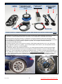
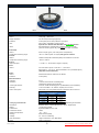
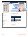
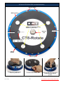
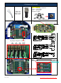
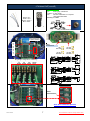
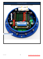
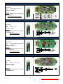
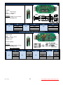
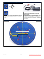
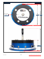
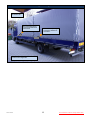
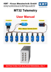
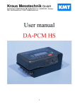
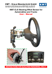
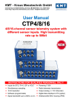
KMT - Kraus Messtechnik GmbH Gewerbering 9, D-83624 Otterfing, Germany, 08024-48737, Fax. 08024-5532 Home Page: http://www.kmt-telemetry.com, Email: [email protected] CT4/8-Wheel/Rotate User Manual STG offset via potentiometer or optional Auto Zero calibration 12 bit ADC resolution, simultaneous sampling of all channels Signal bandwidth: 4 x 0-190 Hz, 8 x 95 Hz with 40kbit Tx 4 x 0-1500 Hz, 8 x 750 Hz with 320kbit Tx 4 x 0-3000 Hz, 8 x 1500 Hz with 640kbit Tx 4 x 0-6000 Hz, 8 x 3000 Hz with 1280kbit Tx Water protected housing (IP65) Output analog (+/- 5V) and digital for PC interface at the receiver side Universal mounting adapter for fast and exactly montage on the wheel 4x different carrier frequencies (only with 40kbit Tx) enable measurements at four Wheels at one car or truck 320...1280kbit with diversity receiver! Accumulator powered (up to 10h) INSTRUCTIONS FOR QUALIFIED PERSONNEL ONLY! General functions: 8 x Sensor cables 2m CT8-Wheel/Rotate encoder with external antenna recommend for 320, 640 and 1280kbit Battery charger CT8-Wheel decoder with receiver Optional diversity! 2x Receiving antenna for diversity receiver with 4m cable DC power cable Picture shows a CT8-Wheel telemetry system with standard accessories and diversity option! CT4/8-Wheel is an telemetry system designed for easy mounting onto rotating Wheels to provide non-contact transmission of measured parameters such as pressure, force, temperature, acceleration and voltage. Sensors inputs are connected via screw on, waterproof connectors. Measured values are prepared in analog format, digitized and transmitted via radio frequencies. Four different carrier frequencies are provided, this allows up to four systems (e.g. for four wheels) to operate in parallel. The complete transmitter assembly is waterproofed to IP65 specifications. The following sensors can be connected to the system: (STG) Strain gages sensors in full-, half- and quarterbridge configuration (350 ohm or greater), Type K Thermocouples -50 to 1000°C, ICP and capacitive sensors. Voltage inputs of +/-5V and +/-10V are available. The measured values are processed and output as +/-5V analog signals at the BNC sockets (optional digital output for special PCM interface into a PC) on the stationary receiver located in a vehicle or helicopter cabin. Resolution of 12 bits is standard; this enables an amplitude dynamic of 72 dB. The analog signal bandwidth is 095 Hz (-3dB) when configured as an eight channel unit, other bandwidth on request! The measurement accuracy is +/-0.25 % (without sensor). The CT4/8-Wheel is suited for operation at ambient temperatures of -20 to +70°C. The transmission distance between transmitter and receiving antenna is of the order of 10-20m with 40kbit depend of application! Truck Wheel “ALCOA” Version 2015-12 2 Technical Data are subject to change without notice! Transmitter Device (Encoder) with internal Tx antenna recommend >40....1280kbit CT8-Wheel CT-STG V1: Sensor: strain gage, 350 Ohms Bridge completion: full, half and quarter-bridge (optional) Excitation: 4 VDC (fixed), short-circuit protection up to 20mA Gain: 200 or 1000 - selectable by solder jumpers Optional Gain: 250-500-1000-2000 with new CT-STG V2 module Offset Zero adjustment by potentiometer or optional Auto-zero function (which is not lost by power-off), offset range up to 80% of full scale. CT-TH-K-ISO: Sensor: thermo-couple, type K ( with cold junction compensation) Temperature measuring range: -50°C to +1000°C (other on request) with galvanic isolation CT-PT100: Sensor: resistance temperature detectors (RTDs) with resistance of 100 ohm Temperature measuring range: -100°C to +500°C CT-VOLT: High-level inputs: +/- 5 Volt or +/- 10 Volt (other ranges on request) CT-ICP: Sensor: For ICP® sensor inputs, Current exc. 1, 4, and 10mA Signal gain x 2, 4, 8, 16, 32 - Signal bandwidth 3 Hz up to 3000Hz (8 CH) (depended of transmitter kbit) CT-POT: Sensor: Potentiometer Sensor >350 Ohms to 10kOhm Excitation: 4 VDC (fixed) System Parameters: Channels: 4 or 8 Resolution: 12 bit A/D converter with anti aliasing filter, simultaneous sampling of all channels Line-of-sight distance: 20 m with 10mW transmitting power (433MHz Band, FSK modulation) Powering: Li Ion Accumulator 7.2V, 2200mA, capacity for 8-10 hours Power consumption: 200 mA (at 7,2V) using 8 STG sensors at 350 Ohms with CT-STG-V1 Cut off frequency from anit-aliasing filter (-3dB) Bit rate Scanning rate (red) 4 Channels 8 Channels 6000 Hz (24615 Hz) 3000 Hz (12308 Hz) 1500 Hz (6154 Hz) 190 Hz (770 Hz) 3000 Hz (12800 Hz) 1500 Hz (6400 Hz) 750 Hz (3200 Hz) 95 Hz (400 Hz) 1280 kbit/s 640 kbit/s 320 kbit/s Analog signal bandwidth: 40 kbit/s depending of transmitter! Dimensions: Diameter 160mm, bottom plate diameter 190mm, height 65mm Weight: 1.50 kg without cables Transmission: Digital PCM Miller format - FSK Transmission Power: 10mW Operating temperature: - 20 … +70°C Housing: Water resistant (IP65) Humidity: 20 ... 80% no condensing Static acceleration: 100g in all directions, max. RPM 2500 Shock: 200g in all directions Version 2015-12 3 Technical Data are subject to change without notice! CT8-Wheel DEC8 Receiver unit for 8 Channels output via BNC (radio telemetry version with diversity option) Front view Rear side view BNC socket for analog signal outputs 1 … 8 Auto Zero LED Bright on, if analog output is over 60mV (Opt. AZ) Out of function! Power Switch HF –Field strength display Transmission error LED Fuse of powering defect LED SMA antenna connector with active LED of antenna (diversity) 7-pole female TUCHEL connector for power supply input (10–30V DC) PCM out for IP-LAN-Interface (Opt.) (Option) System Parameters: Channel: 8 analog outputs via (BNC) +/-5V, Optional +/-10V Resolution: 12 bit D/A converter, with smoothing filter Dynamic: 72dB Power supply input: 10-30 VDC Current consumption: 300mA at 10V, 100mA at 30V Cut off frequency from anit-aliasing filter (-3dB) Bit rate Scanning rate (red) 4 Channels 8 Channels 6000 Hz (24615 Hz) 3000 Hz (12308 Hz) 1500 Hz (6154 Hz) 190 Hz (770 Hz) 3000 Hz (12800 Hz) 1500 Hz (6400 Hz) 750 Hz (3200 Hz) 95 Hz (400 Hz) 1280 kbit/s 640 kbit/s 320 kbit/s Analog signal bandwidth: 40 kbit/s Dimensions: 205 x 105 x 65mm Weight: 1.00 kg without cables and antenna Overall system accuracy between encoder input and decoder output: +/-0.25% without sensor influences, with CT-TH-K-ISO only +/-1% Environmental Operating: -20 … +70°C Humidity: 20 ... 80% not condensing Vibration: 5g Mil Standard 810C, Curve C Static acceleration: 10g in all directions Shock: 100g in all directions Technical specifications are subject to change without notice Version 2015-12 4 Technical Data are subject to change without notice! Functions: 8 Channel CT8-Wheel ENC (encoder/transmitter) Sensor Inputs Battery charge Untwist to open the housing, screws e.g. with coin! Antenna TNC Sensor Inputs Sensor Inputs Green = Power ON Red = Batt. empty ON/OFF Switch Sensor Inputs Untwist to open the housing, screws e.g. with coin! Version 2015-12 To lift the cover, use the slot! 5 Take care with the O-ring seal, it is lubricated with silicone grease! Technical Data are subject to change without notice! Connection, STG bridge configuration: CT8-Wheel ENC (encoder) CT-STG-V1 module Type: Strain gage >350 Ohms Excitation: 4 VDC (fixed) Gain: 200 or 1000 Accuracy +/- 0.25% Black = IN White = IN + Brown = EXC + Blue = EXC - Sensor socket Sensor cable Plug at CT8-Wheel ENC Sensor modules Offset Potentiometer Gain 200 Gain 1000 - factory setting! Offset Potentiometer or optional AutoZero Ch. 8 7 6 5 4 3 2 1 Plug bridge configuration at STG e.g.: Offset calibration and Gain setting: Offset Gain 200 or 1000 potentiometers by solder bridge (1000=Factory setting) Auto Zero calibration Optional! Version 2015-12 6 Technical Data are subject to change without notice! Connection, STG bridge configuration: CT8-Wheel ENC (encoder) CT-STG-V2 module Type: Strain gage >350 Ohms Excitation: 4 VDC (fixed) Gain: 250-500-1000-2000 or on request 1000-2000-4000-8000 Accuracy +/- 0.25% Black = IN White = IN + Brown = EXC + Blue = EXC - Sensor socket Sensor cable Plug at CT8-Wheel ENC Sensor modules Offset Potentiometer or optional AutoZero Ch. 8 7 6 5 4 3 2 1 Offset Potentiometer Plug bridge configuration at STG e.g.: Offset calibration: Offset potentiometers Auto Zero calibration Optional! Version 2015-12 7 Technical Data are subject to change without notice! Connection, STG bridge configuration: CT8-Wheel ENC (encoder) Optional solution for GAIN section at CT-STG V2 module Ch. 8 7 6 5 4 3 2 1 Plug bridge configuration at CT-STG V2 on top side! Optional only Spare for not-use jumpers Version 2015-12 8 Technical Data are subject to change without notice! Connection POT: POT module Type: Potentiometer >350 Ohms Excitation: 4 VDC (fixed) Accuracy +/- 0.25% Attention: The POT modules must be configured as a Half Bridge Unit. Don’t change offset and gain!! Connection Volt +/-5V +/-10V Volt module Type: Volt Range: +/-5 or +/-10V Accuracy +/- 0.25% Attentions: At Volt modules must plug the plug bridge on Half Bridge Unit. Don’t change offset!! Connection Volt-ISO Volt module Type: Volt input with galvanic isolation! Range: +/-5 or +/-10V Accuracy +/- 0.25% Attentions: At Volt modules must plug the plug bridge on Half Bridge Unit. Don’t change offset!! Connection ICP V2 Gain: 32 16 8 4 2 ICP module Type: ICP Gain: 2x, 4x, 8x, 16x or 32x Constant curent: 4mA Accuracy +/- 0.25% Attentions: At Volt modules must plug the plug bridge on Half Bridge Unit. Version 2015-12 9 Technical Data are subject to change without notice! Connection CT-Pt100 module (RTD) CT-Pt100 Type: RTD 100 ohm Range: -100 to 500°C Accuracy +/- 0.25% Attentions: At Thermo couple must plug the plug bridge on Half Bridge Unit. Temperature [°C] -100 -50 0 50 100 Output [V] -0,997 -0,497 0,001 0,499 1,000 Temperature [°C] 150 200 250 300 350 Output [V] 1,500 2,001 2,501 3,001 3,501 Temperature [°C] 400 450 500 Output [V] 4,004 4,498 4,999 Connection Th K-ISO (with galvanic isolation!) Thermo couple Type: K Range: -50°C – 1000°C Bandwidth: 0-20Hz Accuracy +/-1% Galvanic isolated! Attentions: At Thermo couple must plug the plug bridge on Half Bridge Unit. Don’t change offset!! Temperature [°C] -50 0 50 100 150 200 Version 2015-12 Output [V] -0.220 0.013 0.254 0.504 0.752 0.992 Temperature [°C] 250 300 350 400 450 500 Output [V] 1.236 1.482 1.734 1.990 2.242 2.498 10 Temperature [°C] 550 600 650 700 750 800 Output [V] 2.754 3.010 3.266 3.519 3.700 4.015 Temperature [°C] 850 900 950 1000 Output [V] 4.262 4.506 4.746 4.980 Technical Data are subject to change without notice! Li Ion re-chargeable battery with charger unit for CT8-Wheel Charge plug at CT8-Wheel ENC CT-CHARGER for CT8-Wheel Attention: Li Ion battery (7.2V, 2200mA) has a capacity for >6-8 hours. If the red LED indicator, on the Transmitter is ON the battery is 80% discharged and the device will switch off after 20-30 minutes! 1. Plug the 3-pole socket (charger) in to the CT8Wheel encoder. 2. Plug banana plugs on to a battery or AC/DC power supply with a voltage range of 10-30V, 3. Press and hold the switch for 1 second to begin charging. The battery will now charge. Charge time 2-3 hours! Mounting hole dimensions: Do not open these screws (silicon sealed) bolt circle diameter 175 mm Hole diameter 8.1mm Base plate side Version 2015-12 11 Technical Data are subject to change without notice! Dimensions: Hole diameter 8.1 mm 160mm 190mm 65mm 150mm Height incl. screws 70mm Total weight 1.5kg Version 2015-12 12 Technical Data are subject to change without notice! Placing of receiving antennas: Receiver in the driver's cab Recommended placing of receiving antenna for front wheel Recommended placing of receiving antenna for rear wheel Antenna cable between Rx antenna and receiver max. length 25m! Version 2015-12 13 Technical Data are subject to change without notice!