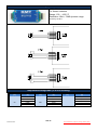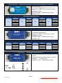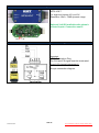
1
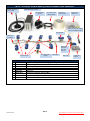
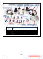
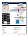
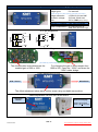
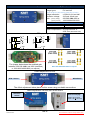
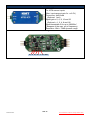
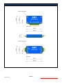
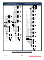
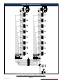
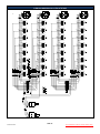
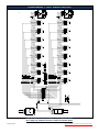
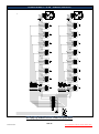
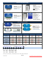
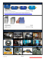
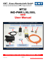
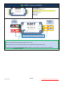
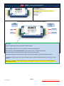
KMT - Kraus Messtechnik GmbH Gewerbering 9, D-83624 Otterfing, Germany, 08024-48737, Fax. 08024-5532 Home Page: http://www.kmt-telemetry.com, Email: [email protected] MT32 Telemetry User Manual INSTRUCTIONS FOR QUALIFIED PERSONNEL ONLY! MT32 - 8 channel set with battery power and 40kbit radio transmitter 433MHz receiving antenna 0dB MT32-DEC8 incl. receiver AC/DC adapter (option) 50 & 25mm mounting tape DC Power cable (MT32-DEC8) Cable set for cable loom MT32-Tx-TNC opt. adapter with mini 433MHz antenna MT32-ENC8 Cable loom (for testing) MT32-40k transmitter with wireantenna 8 x MT32-STG Test bridge STG (option) Terminator Batt. Pack 1 x Batt. Set 1 x extra Order example: MT32-8CH-40k, 8xSTG, BATT, BW 8x0-95Hz 8 MT32-STG Signal conditioning module for strain gages with digital data acquisition 1 MT32-ENC8 Encoder for up to 8 acquisition module 1 MT32-40k-10 ISM-Band telemetry transmitter and receiver (distance up to 0.5 to 10m) 1 BATT-PACK Battery pack 1 BATT-SET Battery set 1 MT32-DEC8 Decoder for 8 channels, Output 8 x BNC 1 AC/DC AC/DC power supply for DEC8 (Optional) 8 MT32-STG Signal conditioning module for strain gages with digital data acquisition Side 2 Version 2015-07 Technical Data are subject to change without notice! MT32 - 8 channel set with inductive power and 2560kbit inductive transmitter MT32-DEC8 incl. receiver 50 & 25mm mounting tape and ferrite tape MT32-Telmetry 50 & 25mm mounting tape and ferrite tape MT32-IND-Power MT32-INDPower supply IND-Power head and DC cable Inductive Pickup with 5m cable and DC power cable Copper wire Cable loom (for testing) MT32-ENC8 8 x MT32-STG Terminator Opt. IND-Tx with test coil IND-AC/DC with opt. test coil Cable set for cable loom Option Order example: MT32-8CH-IND-TX-RX, 8xSTG, IND-PWR, BW 8x0-6000Hz 8 MT32-STG Signal conditioning module for strain gages with digital data acquisition 1 MT32-ENC8 Encoder for up to 8 acquisition module 1 MT32-IND-RX-TX Inductive telemetry 2560kbit transmitter and receiver (distance 0.1m) 1 IND-PWR-L Inductive power supply 1 MT32-DEC8 Decoder for 8 channels, Output 8 x BNC 2 AC/DC AC/DC power supply (1x for DEC8, 1x for IND-PWR) Side 3 Version 2015-07 Technical Data are subject to change without notice! Installation of the MT32 Modules Attach all the MT32 modules on the final position on the shaft using the “tesa® PowerStrips® Mini”. Fix all MT32 modules with at least 10 layers of the special mounting tape around the shaft. According to the shafts RPM and diameter it’s particularly paid attention to safe mounting of the components. The manufacturer doesn’t accept liability for damages, which results from not sufficiently attachment of the individual components. The provided cable harness and the tape are only for test purposes, in order to test the electrical function of the units in the idle state of the shaft. During the rotation test appropriate safety tools are to be attached. The entire installation may be used only by authorized persons. By using tape for the attachment, it has to be used in the direction of rotation of the shaft and the end has to be secured against removing. Only non-elastic tapes with high tensile strength have to be used for pre-fixing. Add. use horse clamps for final fixing!! The individual components are to be distributed in such a way on the shaft that imbalances will avoid. hose clamps All cable connections soldered! The user has to pay attention to connect the wires to the correct pins - the units have no reverse-connect protection! Side 4 Version 2015-07 Technical Data are subject to change without notice! MT32 to consider at assembling According to the shafts RPM and diameter is particularly paid attention to safe mounting of the components. The manufacturer doesn’t accept liability for damages, which results from not sufficiently attachment of the individual components. The provided cable harness and the tape are only for test purposes, in order to test the electrical function of the units in the idle state of the shaft. During the rotation test appropriate safety tools are to be attached. The entire installation may be used only by authorized persons. By using tape for the attachment, it has to be used in the direction of rotation of the shaft and the end has to be secured against removing. Only nonelastic tapes with high tensile strength have to be used. The individual components are to be distributed in such a way on the shaft that imbalances will avoid. All wire connections should be soldered. The user has to pay attention to the correct polarity of the cables – the units have no reverse-connect protection! Transmitting antennas and sensors should not be installed next to each other. To ensure a reliable function, the receiving antenna should be positioned in such a way that all LEDs lights up at the field level display on the receiver. Don’t plug any modules if Power is ON!!! First power OFF!! Side 5 Version 2015-07 Technical Data are subject to change without notice! MT32-40-320-640 or 1280k Installation of the radio transmitter on a shaft Cable Red = +5V Cable Black = GND (Ground) Cable Brown = PCM In Cable White = Wire antenna All cable connections should be soldered. Mount the cable antenna exactly one winding around the shaft and fix all with 3 windings mounting tape – finish! The cable antenna can extend or shorten depending upon requires! (isolate the solder connection, if you extend the wire antenna cable!) This coaxial adapter (MT32-40k-Tx-TNC-adapter) makes it possible to connect a 433 MHz antenna with TNC connector for point to point applications. (option) 433 MHz transmitting antenna 0dB with magnetic foot (option) Side 6 Version 2015-07 Technical Data are subject to change without notice! MT32-IND-TX-RX with 45MHz carrier! With 45MHz carrier is only 1x winding necessary! Attach for electromagnetic insulation “Ferrite Tape” 2 x one layer around the shaft. Make transmitting coil with 1x winding and twisted the end of wire. Use CUL 1mm wire (CUL = Enamelled copper wire) Fixed it with 3 layers mounting tape Extend the CUL wire flexible 0.14-0.25mm wire (to decouple the inflexible 1mm wire!) Twisted also the flexible wire and solder it on the MT32IND-Tx (isolate all solder points with shrink tubing) Side 7 Version 2015-07 Technical Data are subject to change without notice! MT32-IND-TX-RX with 45MHz carrier! Pickup head max. 100mm 3 … 100mm (Typical 50mm) Inductive Pick-Up head mount in this position! Distance between head and Tx coil can be up to 100mm Typical 50mm, distance deepens of application!! To avoid transmitting problems, the transmitter module must be close the transmitting antenna! The cables (PCM/GND/+5V) between MT32-IND-TX 45MHz and ENC8/16 can be 1000mm long! CAUTION: If you want to install also an inductive power coil close to the data coil, the minimal distance must be <10mm! (distance between IND-PWR coil to IND-DATA coil) Side 8 Version 2015-07 Technical Data are subject to change without notice! MT32 Block diagram IND-TX-RX with 45MHz carrier and inductive power Side 9 Version 2015-07 Technical Data are subject to change without notice! MT32 Block diagram IND-TX-RX with 45MHz diversity with two 45MHz carrier pickup heads at large shafts (>500mm) At shaft diameter lager then >500mm diameter, you can get zero points in the 45MHz antenna. To avoid transmitting loss, we recommend using a second pickup head! The distance between two pickup heads must be 45° to 90°. On the MT-DECODER (receiver) you can see the yellow status LED of Pickup. At good magnetic level, the LED is bright and Pickup is active. Input for IND-Pickup A Yellow LED show active pickup head Input for IND-Pickup B Side 10 Version 2015-07 Technical Data are subject to change without notice! Picture of IND-PICKUP-HEAD 45MHz Side 11 Version 2015-07 Technical Data are subject to change without notice! Dimensions of IND-PICKUP-HEAD 45MHz Side 12 Version 2015-07 Technical Data are subject to change without notice! MT32-DEC8 Front view Receiver unit for 8 Channels output via BNC (radio telemetry version) Back view BNC socket for analog signal outputs 1 … 8 TNC-socket for receiving antenna Field strength indicator Power ON - LED ON/OFF - switch 7- pole TUCHEL-socket for Voltage supply cable (10–30V) Sync-Loss Indicator LED System Parameters: Channel: 8 analog outputs via (BNC) +/-5V Resolution: 12 bit D/A converter, with smoothing filter Dynamic: 72dB Power supply input: 10-30 VDC Current consumption: 300mA at 10V, 100mA at 30V Cut off frequency from anit-aliasing filter (-3dB) Bit rate Scanning rate (red) 4 Channels 8 Channels 6000 Hz (24615 Hz) 3000 Hz (12308 Hz) 1500 Hz (6154 Hz) 190 Hz (770 Hz) 3000 Hz (12800 Hz) 1500 Hz (6400 Hz) 750 Hz (3200 Hz) 95 Hz (400 Hz) 1280 kbit/s 640 kbit/s 320 kbit/s Analog signal bandwidth: 40 kbit/s Dimensions: 205 x 105 x 65mm Weight: 1.00 kg without cables and antenna Overall system accuracy between encoder input and decoder output: +/-0.25% without sensor influences, with CT-TH-K-ISO only +/-1% Environmental Operating: -20 … +70°C Humidity: 20 ... 80% not condensing Vibration: 5g Mil Standard 810C, Curve C Static acceleration: 10g in all directions Shock: 100g in all directions Technical specifications are subject to change without notice Side 13 Version 2015-07 Technical Data are subject to change without notice! MT32-DEC8 Receiver unit for 8 Channels output via BNC (radio telemetry version with diversity option) Front view Rear side view BNC socket for analog signal outputs 1 … 8 Auto Zero LED Bright on, if analog output is over 60mV (Opt. AZ) Out of function! Power Switch HF –Field strength display Transmission error LED Fuse of powering defect LED SMA antenna connector with active LED of antenna (diversity) 7-pole female TUCHEL connector for power supply input (10–30V DC) PCM out for IP-LAN-Interface (Opt.) (Option) System Parameters: Channel: 8 analog outputs via (BNC) +/-5V, Optional +/-10V Resolution: 12 bit D/A converter, with smoothing filter Dynamic: 72dB Power supply input: 10-30 VDC Current consumption: 300mA at 10V, 100mA at 30V Cut off frequency from anit-aliasing filter (-3dB) Bit rate Scanning rate (red) 4 Channels 8 Channels 6000 Hz (24615 Hz) 3000 Hz (12308 Hz) 1500 Hz (6154 Hz) 190 Hz (770 Hz) 3000 Hz (12800 Hz) 1500 Hz (6400 Hz) 750 Hz (3200 Hz) 95 Hz (400 Hz) 1280 kbit/s 640 kbit/s 320 kbit/s Analog signal bandwidth: 40 kbit/s Dimensions: 205 x 105 x 65mm Weight: 1.00 kg without cables and antenna Overall system accuracy between encoder input and decoder output: +/-0.25% without sensor influences, with CT-TH-K-ISO only +/-1% Environmental Operating: -20 … +70°C Humidity: 20 ... 80% not condensing Vibration: 5g Mil Standard 810C, Curve C Static acceleration: 10g in all directions Shock: 100g in all directions Technical specifications are subject to change without notice Side 14 Version 2015-07 Technical Data are subject to change without notice! MT32-DEC16/32 Receiver unit for max 16/32 Channels output via 37 pol. Sub D (radio telemetry version with diversity option) Front side view Female 37 pole Sub-D for analog signal output, CH 1 to 16 Rear side view Auto Zero LED Bright on, if analog output is over 60mV (Opt. AZ) Out of function! Power Switch HF –Field strength display Transmission error LED Fuse of powering defect LED SMA antenna connector with active LED of antenna (diversity) 7-pole female TUCHEL connector for power supply input (10–30V DC) PCM out for IP-LAN-Interface (Opt.) (Option) Optional BNC16 Box. Connect on 37pol Sub-D Plug-side MT32-DEC16 System Parameters: Channel: 16x +/-5V (+/-10V Option) analog outputs via Sub-D male socket Resolution: 12 bit D/A converter, with smoothing filter Dynamic: 72dB Power supply input: 10-30 VDC, power consumption 10 Watt Current consumption: 300mA at 10V, 100mA at 30V Transmission: Digital PCM Miller Format – FSK, diversity receiver Dimensions: 205 x 105 x 65mm Weight: 1.25 kg without cables and antenna Overall system accuracy between encoder input and decoder output: +/-0.25% without sensor influences Environmental Operating: -20 … +70°C Humidity: 20 ... 80% not condensing Vibration: 5g Mil Standard 810C, Curve C Static acceleration: 10g in all directions Shock: 100g in all directions Side 15 Version 2015-07 Technical Data are subject to change without notice! MT32-DEC16/32 Receiver unit for max 16/32 Channels output via 37 pol. Sub D (inductive pickup head with diversity option) Rear side view Front side view Female 37 pole Sub-D for analog signal output, CH 1 to 16 Out of function! Input for IND-Pickup A Power Switch Yellow LED show active pickup head Transmission error LED Fuse of powering defect LED Input for IND-Pickup B 7-pole female TUCHEL connector for power supply input (10–30V DC) Optional BNC16 Box. Connect on 37pol Sub-D Plug-side CT16- -DEC16 System Parameters: Channel: 16x +/-5V (+/-10V Option) analog outputs via Sub-D male socket Resolution: 12 bit D/A converter, with smoothing filter Dynamic: 72dB Power supply input: 10-30 VDC, power consumption 10 Watt Current consumption: 300mA at 10V, 100mA at 30V Transmission: Digital PCM Miller Format – FSK, diversity receiver Dimensions: 205 x 105 x 65mm Weight: 1.25 kg without cables and antenna Overall system accuracy between encoder input and decoder output: +/-0.25% without sensor influences Environmental Operating: -20 … +70°C Humidity: 20 ... 80% not condensing Vibration: 5g Mil Standard 810C, Curve C Static acceleration: 10g in all directions Shock: 100g in all directions Side 16 Version 2015-07 Technical Data are subject to change without notice! MT32-STG-V1 Acquisition module for strain gages (STG) MT32-STG-V1 Bridge types: Full and half (quarter bridge only with external completions resistor!) Bridge resistance: Excitation voltage: Gain: ≥ 350 for full and half 4V fixed, 20mA max. 200 or 1000 (factory setting) Gain and STG- ensitivity (output +/-5V at decoder) Gain 200 = +/ 6.25mV/V Gain 1000 = +/-1.25mV/V Offset compensation: By potentiometer or Auto Zero (80% of full range) 1 +4V 2 1/2 2 1/2 3 -In 4 +In 5 GND Half bridge completion 1 +4V Half bridge Full bridge STG pin assignment 3 -In 4 +In 5 GND Gain setting (Selectable by solder bridge!) The closed solder bride determines the enabled gain of 200 or 1000. For changing the gain in this example from 1000 to 200 - open the “1000x” and close the “200x” solder bridge. Offset adjustment via Poti MT32-ENC8 STG - Sensor The offset adjustment takes place via this screw using a suitable screw driver Offset adjustment via Auto Zero at the ENC8 Auto Zero Switch Auto Zero display LED Off = AZ successful LED On = AZ not successful Side 17 Version 2015-07 Technical Data are subject to change without notice! MT32-STG-V2 Acquisition module for strain gages (STG) MT32-STG-V2 Bridge types: Full and half (quarter bridge only with external completions resistor!) Bridge resistance: Excitation voltage: Gain: (factory setting) (specify at order) ≥ 350 for full and half 4V fixed, 20mA max. 250-500-1000-2000 or 1000-2000-4000-8000 Gain and STG-Sensitivity (output +/-5V at decoder) Gain 250 = +/-5mV/V Gain 500 = +/-2.5mV/V Gain 1000 = +/-1.250mV/V Gain 2000 = +/-0.625mV/V Gain 4000 = +/-0.3125mV/V Gain 8000 = +/-0.15625 mV/V Offset compensation: By potentiometer or Auto Zero (80% of full scale) 1 +4V 2 1/2 2 1/2 3 -In 4 +In 3 -In 4 +In 5 GND Half bridge completion 1 +4V Half bridge Full bridge STG pin assignment 5 GND Gain setting The jumper determines the enabled gain between 250-500-1000- and 2000 (standard) Gain 1000-2000-4000-8000 on request! or 1000-2000-4000-8000 (on request) Offset adjustment via Poti MT32-ENC8 STG - Sensor The offset adjustment takes place via this screw using a suitable screw driver Offset adjustment via Auto Zero at the ENC8 Auto Zero Switch Auto Zero display LED Off = AZ successful LED On = AZ not successful Side 18 Version 2015-07 Technical Data are subject to change without notice! MT32-ICP Acquisition module for ICP MT32-ICP For ICP® sensor inputs (Max. input range at gain 2x = ±2.5V) Current exc. 4mA fixed (Optional 1mA) Signal gain x 2, 4, 8, 16 and 32 (Optional x 1, 2, 4, 8 and 16) Signal bandwidth 3 Hz up to 24000Hz* (*deepens of the max. cut of frequency) Resolution 12bit = 72dB dynamic range Gain setting 2x, 4x, 8x, 16x, or 32x Gain Side 19 Version 2015-07 Technical Data are subject to change without notice! MT32-PT100 Acquisition module for PT100 MT32-PT100 For thermo resistors Range -100 …+500 °C Resolution 12bit = 72dB dynamic range Accuracy <0.25% Temperature/Voltage table (+/-0.25% accuracy) Temperature [°C] -100 -50 Output [V] -0,997 -0,497 Temperature [°C] 150 200 Output [V] 1,500 2,001 Temperature [°C] 400 450 Output [V] 4,004 4,498 0 50 100 0,001 0,499 1,000 250 300 350 2,501 3,001 3,501 500 4,999 Side 20 Version 2015-07 Technical Data are subject to change without notice! MT32-THK-ISO Acquisition module for TH K-ISO with galvanic isolation!) MT32-TH K-ISO For thermo couples type K (with galvanic isolation!) Range -50 to 1000 °C (other range on request) Bandwidth 0-10Hz Resolution 12bit = 72dB dynamic range Accuracy <1% Temperature/Voltage table Temperature [°C] -50 0 50 100 150 200 Output [V] -0.220 0.013 0.254 0.504 0.752 0.992 Temperature [°C] 250 300 350 400 450 500 MT32-THK Output [V] 1.236 1.482 1.734 1.990 2.242 2.498 Temperature [°C] 550 600 650 700 750 800 Output [V] 2.754 3.010 3.266 3.519 3.766 4.015 Temperature [°C] 850 900 950 1000 Output [V] 4.262 4.506 4.746 4.980 Acquisition module for TH K MT32-TH (without galvanic isolation!) For thermo couples type K Range 0 to 1000 °C (other range on request) Bandwidth 0-10Hz Resolution 12bit = 72dB dynamic range Accuracy <1% Temperature/Voltage table Temperature [°C] 0 50 100 150 200 Output [V] -5,003 -4,515 -4,009 -3,516 -3,031 Temperature [°C] 250 300 350 400 450 MT32-POT Output [V] -2,546 -2,044 -1,538 -1,029 -0,515 Temperature [°C] 500 550 600 650 700 Output [V] 0,002 0,515 1,031 1,542 2,052 Temperature [°C] 750 800 850 900 1000 Output [V] 2,558 3,061 3,550 4,035 5,000 Acquisition module for POT MT-POT For all potentiometer values 350Ohm to 10kOhm Excitation: 4 VDC (fixed) Resolution 12bit = 72dB dynamic range Side 21 Version 2015-07 Technical Data are subject to change without notice! MT32-VOLT Acquisition module for Volt MT32-VOLT For high level inputs ±5V or ±10V Resolution 12bit = 72dB dynamic range Optional Volt ISO available with galvanic isolated inputs. Connection same! +/-10V +/-5V MT32 Termination of CLK and CS signal Important: MT32-Termination-Plug The CLK and CS signal must be terminated (from 8-32 channels necessary!) See pin connection diagram: Side 22 Version 2015-07 Technical Data are subject to change without notice! MT32-Hall Acquisition module for Hall-Sensor by 10mA: 9,5mV / KG Offset compensation: FH-301-040 By potentiometer (80% of full range) Hall pin assignment Resolution 12bit = 72dB dynamic range Gain setting The closed solder bride determines the enabled gain of 15 or 25 or 35 Side 23 Version 2015-07 Technical Data are subject to change without notice! MT32 acquisition modules - dimensions Side 24 Version 2015-07 Technical Data are subject to change without notice! Pin connection e: 1x ENC8, 2x STG/VOLT 1x ENC8, 4x STG/VOLT/TH-K/ ICP-V2 Pin connection e.g.: 1x ENC8, 8x STG/VOLT/TH-K/ ICP-V2 Termination not necessary at 2-CH and 4-CH loom! Take care with your pin connection, if you solder the cable! Don’t plug any modules if Power is ON!!! First power OFF!! Side 25 Version 2015-07 Technical Data are subject to change without notice! Pin connection: 1x ENC16, 16x STG/VOLT/TH-K/ ICP-V2 Take care with your pin connection, if you solder the cable! Don’t plug any modules if Power is ON!!! First power OFF!! Side 26 Version 2015-07 Technical Data are subject to change without notice! Pin connection CH 1-32 (not split): 1x ENC32 MASTER and 1x ENC32 SLAVE Side 27 Version 2015-07 Technical Data are subject to change without notice! Pin connection split into CH 17-32: 1x ENC32 MASTER, 1…16 CH STG/VOLT/TH-K/ ICP-V2 Take care with your pin connection, if you solder the cable! Don’t plug any modules if Power is ON!!! First power OFF!! Side 28 Version 2015-07 Technical Data are subject to change without notice! Pin connection split into CH 1-16: 1x ENC32 SLAVE, 17…32 CH STG/VOLT/TH-K/ ICP-V2 Take care with your pin connection, if you solder the cable! Don’t plug any modules if Power is ON!!! First power OFF!! Side 29 Version 2015-07 Technical Data are subject to change without notice! Short description: The MT32 Mini-Telemetry is a very small and flexible telemetry system for rotating, mobile and stationary applications. Each sensor module is equipped with signal conditioning, anti-aliasing filters, analog-to-digital converters and a digital output. All these up to 32 modules will controlled by an encoder (multiplexer with PCM output) module. By this concept it’s possible to install the acquisition modul es close to the sensor to have short connections for the analog sensor lines. This avoids an undesired coupling of distur bances resulting in noisy signals. The interference insensitive digital outputs then can lead over wider distances of up to 5m to the encoder module. The encode r output is a PCM bit stream signal which can be modulated for emission by a transmitter module. To support a wide range of applications there are different HF- transmitter types available. This includes different distances (short and long), transmission rates (40, 320, 640, 1280 or 2560kbit/s). Please send us an exactly description of your application with a simple block diagram. This ensures to provide you a proposal for an optimal solution. The supply voltage for the transmitting part is 5V DC. It can be generated by batteries, inductive or mains power supplies (d epends on application). Optional it’s also possible to combine all signal acquisition modules, encoder, transmitter and batteries in a small housing as a compact ready-to-use telemetry system (CT8-16). For strain gage applications the offset can compensated by potentiometer on the acquisition module or optional by auto-zeroing via a micro switch on the encoder simultaneously for all modules. The calibration settings are not affected during power off. The receiver station output the signals in a ± 5V full scale range via BNC connectors. It will powered with 1030V DC or optional by an external mains power supply with 110-230V AC. Side 30 Version 2015-07 Technical Data are subject to change without notice! MT32 acquisition modules 52 x 27 x 11 mm Weight 20 grams 52 x 27 x 11 mm Weight 20 grams MT32-STG V1 For strain gages Full and half (≥350) (quarter bridge only with external completions resistor!) Fixed excitation 4V DC Offset calibration via potentiometer or optional auto-zeroing Gain 200 or 1000 Anti aliasing filter Resolution 12bit = 72dB dynamic range Accuracy <0.25% Consumption of current: 20mA MT32-STG V2 For strain gages Full and half (≥350) (quarter bridge only with external completions resistor!) Fixed excitation 4V DC Offset calibration via potentiometer or optional auto-zeroing Gain: 250-500-1000-2000 or 1000-2000-4000-8000 Specify at order Anti aliasing filter Resolution 12bit = 72dB dynamic range Accuracy <0.25% Consumption of current: 26mA 52 x 27 x 11 mm Weight 20 grams 52 x 27 x 11 mm Weight 20 grams MT32-PT100 For thermo resistors Range -100 …+500 °C Resolution 12bit = 72dB dynamic range Accuracy <0.25% Consumption of current:5mA MT32-VOLT For high level inputs ±5V or ±10V Resolution 12bit = 72dB dynamic Accuracy <0.25% Consumption of current: 10mA MT32-ICP For ICP® sensor inputs (Max. input range at gain 2x = ±2.5V) Current exc. 4mA (optional 1mA) Signal gain x 2, 4, 8, 16 and 32 (optional x 1, 2, 4, 8 and 16) Signal bandwidth 3 Hz up to 12000Hz* 52 x 27 x 11 mm Weight 20 grams MT32-POT For all potentiometer values 350Ohm to 10kOhm Excitation:4 VDC (fixed) Resolution 12bit = 72dB dynamic range Anti aliasing filter Accuracy <0.25% Consumption of current:20mA 52 x 27 x 11 mm Weight 20 grams (*dependent of the max. cut of frequency) Resolution 12bit = 72dB dynamic range Accuracy <0.25% Consumption of current: 50mA 52 x 27 x 11 mm Weight 20 grams Optional Volt ISO available with galvanic isolated inputs MT32-TH K-ISO For thermo couples type K (with galvanic isolation!) Range -50 to 1000 °C (other range on request) Resolution 12bit = 72dB dynamic range Bandwidth 0-10Hz Accuracy <1% Consumption of current:12mA MT32 power supply rotating part Lithium battery from SAFT: 2xLSH14, 3.6V each, 5800mAh 2x 3.6V = 7.2V with 5800mAh or 2x LSH20, 3.6V each, 13000mAh 2x 3.6V = 7.2V with 13000mAh DC/DC PWR-5V-1000 Input 7…30V DC Output 5V DC Max. current 1000mA 52 x 27 x 11 mm Weight 20 grams This is only a recommendation! The use of lithium batteries follow at one's own risk!! MT32-BATT-PACK Input 6V via Lithium battery CR-P2 6V 1500mA/h Output 5V DC Low BATT LED display Max. current 300mA 58 x 35 x 21 mm Weight about 60gram IND-Pwr-AC/DC module 52 x 27 x 11 mm Weight 20 grams This is only a recommendation! The use of lithium batteries follow at one's own risk!! MT32- inductive AC/DC PWR 5V Input AC 20-30kHz Output 5V DC Max. current 500mA For inductive IND-PWR AC/DC module is an additional power supply necessary! Side 31 Version 2015-07 Technical Data are subject to change without notice! MT32 encoder and decoder MT32-DEC8 Receiver for up to 2, 4 or 8 channels ±5V output range on female BNC Total system accuracy ±0,25% without sensors Powering 10–30V DC or optional 110-230V AC (50Hz60Hz) with AC/DC adaptor MT32-ENC8 PCM encoder module for linking the data of up to 8 SC modules to one PCM bit stream for transmission Consumption of current: 20mA 52 x 27 x 11 mm Weight 20 grams 65 x 105 x 230 mm - Weight 1000 grams MT32-DEC16 Receiver for 16 channels ±5V output range Output 37pol. Sub D Total system accuracy ±0,25% without sensors Powering 10–30V DC or optional 110-230V AC with AC/DC adaptor MT32-ENC16 PCM encoder module for linking the data of up to 16 SC modules to one PCM bit stream for transmission. Consumption of current: 20mA 52 x 27 x 11 mm Weight 20 grams MT32-DEC16 65 x 105 x 230 mm Weight 1000 grams Option :BNC16 Option: BNC16, adaptor Box 37 Sub-D to 16 x BNC Outputs MT32 transmitter module MT32-IND-Tx-2560k Inductive data transmission transmitter Total sampling rate 160 kS/s Transmission rate 2560kbit/s Distance up to 0.1m (>100mm) Consumption of current: 15mA 52 x 27 x 11 mm Weight 20 grams MT32-40k (320-640-1280k available) Range 10m on rotating applications. Total scanning rate 2,5 kS/s Transmission rate 40kbit/s Transmission power 10mW Consumption of current: 40mA MT32-IND-Tx-45MHz-2560k Inductive data transmission transmitter with 45MHz carrier (for noise environmental areas!) Total sampling rate 160 kS/s Transmission rate 2560kbit/s Distance up to 0.1m (>100mm) Consumption of current: 70mA 52 x 27 x 11 mm Weight 25 grams 52 x 27 x 11 mm Weight 23 grams Cut off frequency from anti-aliasing filter (-3dB), scanning rate (red), latency time (brown) analog IN/OUT Bit rate 2 Channels 4 Channels 8 Channels 16 Channels 32 Channels 24000Hz (91428 Hz) 0.079ms 12000 Hz (45714 Hz) 0.154ms 6000 Hz (22857Hz) 0.305ms 3000 Hz (11428 Hz) 0.597ms 375 Hz (1428 Hz) 4.9ms 12000 Hz (49231 Hz) 0.149ms 6000 Hz (24615 Hz) 0.295ms 3000 Hz (12308 Hz) 0.578ms 1500 Hz (6154 Hz) 1.14ms 190 Hz (770 Hz) 9.4ms 6000 Hz (25600 Hz) 0.29ms 3000 Hz (12800 Hz) 0.57ms 1500 Hz (6400 Hz) 1.12ms 750 Hz (3200 Hz) 2.26 ms 95 Hz (400 Hz) 17.8ms 3000 Hz (13061Hz) 0.56ms 1500 Hz (6530 Hz) 1.11ms 750 Hz (3265 Hz) 2.24ms 375 Hz (1632 Hz) 4.64ms 47 Hz (204 Hz) 35,0ms 1500 Hz (6598Hz) 1.108ms 750 Hz (3298 Hz) 2.23ms 375 Hz (1649 Hz) 4.6ms 190 Hz (824 Hz) 9.1ms 23 Hz (103 Hz) 69.3ms 2560 kbit/s 1280 kbit/s 640 kbit/s 320 kbit/s 40 kbit/s Scanning rate, signal bandwidth and frame length depending on bit rate and number of channels Frame example with 8 channels as following: 8Ch x12 bit = 96 bit + 4 bit sync. = 100 bit 1 Ch. 2 Ch. 3 Ch. 4 Ch. 1x data frame 5 Ch. 6 Ch. 7 Ch. 8 Ch. Sync. bit 12 bit 12 bit 12 bit 12 bit 12 bit 12 bit 4 bit 32 Ch. x 16 Ch. x 8 Ch. x 4 Ch. x 2 Ch. x 12 bit = 12 bit = 12 bit = 12 bit = 12 bit = 12 bit 12 bit = bit rate100 bit 384 bit + 4 bit sync. = 388 bit 192 bit + 4 bit sync. = 196 bit 96 bit + 4 bit sync. = 100 bit 48 bit + 4 bit sync. = 52 bit 24 bit + 4 bit sync. = 28 bit Scanning you can calculate e.g.: 40kbit transfer rate, 8 Ch. = 40000 : 100bit = 400Hz per Ch. Side 32 Version 2015-07 Technical Data are subject to change without notice! Environmental: Rotating Part (blue modules): Operating Temperature ......................................................................................................................................-20 – +80°C Storage Temperature..........................................................................................................................................-30 – +90°C Humidity (non-condensing) ..................................................................................................................................... 20 – 80% Vibration ................................................................................................................................ 5g Mil standard 810C, curve C Shock & static acceleration (in any direction) ............................................................................................................. 3000g Down load formula (Excel format) to calculate the static acceleration (RPM/diameter): http://www.kmt-gmbh.com/en/telemetrie/Calculation of radial acceleration of shaft.xls Receiving Part: Operating Temperature ......................................................................................................................................-10 – +70°C Storage Temperature..........................................................................................................................................-20 – +80°C Humidity (non-condensing) ..................................................................................................................................... 20 – 80% Vibration ................................................................................................................................ 5g Mil standard 810C, curve C Shock (in any direction) ................................................................................................................................................. 100g Application Streetcar wheel Railway wheel Railway wheel Railway wheel Belt disk of car Drive shaft of ship engines Shaft of wind power plant Test rigs Drive shaft of wheel loader Force measurements 24kHz data transmission TTL Special solution for force test at milling machine Side 33 Version 2015-07 Technical Data are subject to change without notice! Item Qty. Type 2 1 1 1 1 1 1 MT32-STG-V2 NEW MT32-ENC8 MT32-40k-10-DIV BATT-PACK BATT-SET MT32-DEC2 AC/DC Description Order Samples MT32-2CH-40k-DIV, 2xSTG, BATT, BW 2x0-375Hz Signal conditioning module for strain gages - gain 250-500-1000-2000 Encoder for up to 8 acquisition module RF telemetry transmitter and diversity receiver with 40kbit (2,5kS/s) Battery pack Battery set Decoder for 2 channels, Output 2 x BNC AC/DC power supply for DEC2 (Optional) 2 1 1 1 1 1 1 MT32-STG-V2 NEW MT32-ENC8 MT32-IND-TX-RX-45MHz BATT-PACK BATT-SET MT32-DEC2 AC/DC MT32-2CH-IND-TX-RX, 2xSTG, BATT, BW 2x0-24000Hz Signal conditioning module for strain gages - gain 250-500-1000-2000 Encoder for up to 8 acquisition module Inductive telemetry transmitter and receiver, 45MHz carrier, 2560kbit Battery pack Battery set Decoder for 2 channels, Output 2 x BNC AC/DC power supply for DEC2 (Optional) 2 1 1 MT32-STG-V2 NEW MT32-ENC8 MT32-IND-TX-RX-45MHz MT32-2CH-IND-TX-RX, 2xSTG, IND-PWR, BW 2x0-24000Hz Signal conditioning module for strain gages - gain 250-500-1000-2000 Encoder for up to 8 acquisition module Inductive telemetry transmitter and receiver, 45MHz carrier, 2560kbit 1 1 1 IND-PWR-L MT32-DEC2 AC/DC Inductive power supply Decoder for 2 channels, Output 2 x BNC AC/DC power supply for DEC2 (Optional) 1 AC/DC-24V-2.5A AC/DC power supply 65 WATT for IND-Power Supply L/XL 4 1 1 1 1 1 1 MT32-STG-V2 NEW MT32-ENC8 MT32-40k-10-DIV BATT-PACK BATT-SET MT32-DEC4 AC/DC MT32-4CH-40k-DIV, 4xSTG, BATT, BW 4x0-190Hz Signal conditioning module for strain gages - gain 250-500-1000-2000 Encoder for up to 8 acquisition module RF telemetry transmitter and diversity receiver with 40kbit (2,5kS/s) Battery pack Battery set Decoder for 4 channels, Output 4 x BNC AC/DC power supply for DEC4 (Optional) 4 1 1 1 1 1 1 MT32-STG-V2 NEW MT32-ENC8 MT32-IND-TX-RX-45MHz BATT-PACK BATT-SET MT32-DEC4 AC/DC MT32-4CH-IND-TX-RX, 4xSTG, BATT, BW 4x0-12000Hz Signal conditioning module for strain gages - gain 250-500-1000-2000 Encoder for up to 8 acquisition module Inductive telemetry transmitter and receiver, 45MHz carrier, 2560kbit Battery pack Battery set Decoder for 4 channels, Output 4 x BNC AC/DC power supply for DEC4 (Optional) 8 1 1 1 1 1 1 MT32-STG-V2 NEW MT32-ENC8 MT32-320k-10-DIV BATT-PACK BATT-SET MT32-DEC8 AC/DC MT32-8CH-320k-DIV, 8xSTG, BATT, BW 8x0-750Hz Signal conditioning module for strain gages - gain 250-500-1000-2000 Encoder for up to 8 acquisition module RF telemetry transmitter and diversity receiver with 320kbit (20kS/s) Battery pack Battery set Decoder for 8 channels, Output 8 x BNC AC/DC power supply for DEC8 (Optional) Side 34 Version 2015-07 Technical Data are subject to change without notice! Item Qty. Type 8b Description Order Samples 8 1 1 1 1 1 1 MT32-STG-V2 NEW MT32-ENC8 MT32-IND-TX-RX-45MHz BATT-PACK BATT-SET MT32-DEC8 AC/DC MT32-8CH-IND-TX-RX, 8xSTG, BATT, BW 8x0-6000Hz Signal conditioning module for strain gages - gain 250-500-1000-2000 Encoder for up to 8 acquisition module Inductive telemetry transmitter and receiver, 45MHz carrier, 2560kbit Battery pack Battery set Decoder for 8 channels, Output 8 x BNC AC/DC power supply for DEC8 (Optional) 8 1 1 1 1 1 1 MT32-STG-V2 NEW MT32-ENC8 MT32-IND-TX-RX-45MHz BATT-PACK BATT-SET MT32-DEC8 AC/DC MT32-8CH-IND-TX-RX-45MHz, 8xSTG, BATT, BW 8x0-6000Hz Signal conditioning module for strain gages - gain 250-500-1000-2000 Encoder for up to 8 acquisition module Inductive telemetry transmitter and receiver, 45MHz carrier, 2560kbit Battery pack Battery set Decoder for 8 channels, Output 8 x BNC AC/DC power supply for DEC8 (Optional) 1 1 MT32-STG-V2 NEW MT32-ENC8 MT32-IND-TX-RX-45MHz BATT-PACK BATT-SET MT32-DEC-DIG-IP-LAN REMUS-Lab AC/DC MT32-8CH-IND-TX-RX, 8xSTG, BATT, BW 8x0-6000Hz, DIG-OUT only Digital OUT, with LAN IP interface and MLAB software Signal conditioning module for strain gages - gain 250-500-1000-2000 Encoder for up to 8 acquisition module Inductive telemetry transmitter and receiver, 45MHz carrier, 2560kbit Battery pack Battery set Digital decoder with PCM-LAN-IP interface 32bit data acquisition and on-line processing software for WinXP/WIN7 AC/DC power supply for DEC-DIG (Optional) 8 1 1 MT32-STG-V2 NEW MT32-ENC8 MT32-IND-TX-RX-45MHz MT32-8CH-IND-TX-RX 45MHz, 8xSTG, IND-PWR, BW 8x0-6000Hz Signal conditioning module for strain gages - gain 250-500-1000-2000 Encoder for up to 8 acquisition module Inductive telemetry transmitter and receiver, 45MHz carrier, 2560kbit 1 1 1 IND-PWR-L MT32-DEC8 AC/DC Inductive power supply Decoder for 8 channels, Output 8 x BNC AC/DC power supply for DEC8 1 AC/DC-24V-2.5A AC/DC power supply 65 WATT for IND-Power Supply L/XL 6 2 1 1 1 1 1 1 MT32-STG-V2 NEW MT32-ICP MT32-ENC8 MT32-IND-TX-RX-45MHz BATT-PACK BATT-SET MT32-DEC8 AC/DC MT32-8CH-IND-TX-RX 6xSTG, 2 x ICP, BATT, BW 8x0-6000Hz Signal conditioning module for strain gages - gain 250-500-1000-2000 Signal conditioning module for ICP sensors with digital data acquisition Encoder for up to 8 acquisition module Inductive telemetry transmitter and receiver, 45MHz carrier, 2560kbit Battery pack Battery set Decoder for 8 channels, Output 8 x BNC AC/DC power supply 16 1 1 1 1 1 1 MT32-STG-V2 NEW MT32-ENC16 MT32-IND-TX-RX-45MHz DC/DC PWR-5V-1000 MT32-DEC16 BNC16 BOX AC/DC MT32-16CH-IND-TX-RX 45MHz, 16xSTG, BATT, BW 16x0-3000Hz Signal conditioning module for strain gages - gain 250-500-1000-2000 Encoder for up to 16 acquisition module Inductive telemetry transmitter and receiver, 45MHz carrier, 2560kbit Power module for blue modules, IN 7-30V OUT 1000mA 5VDC Decoder for 16 channels, Output via 37pol. Sub-D Connector Adapter BOX for DEC16 multiple 37pole Sub-D to 16 single BNC connectors AC/DC power supply 8 1 1 1 1 1 Side 35 Version 2015-07 Technical Data are subject to change without notice! Item Qty. Type Description Order Samples 1 1 MT32-STG-V2 NEW MT32-ENC16 MT32-IND-TX-RX-45MHz DC/DC PWR-5V-1000 MT32-DEC-DIG-IP-LAN REMUS-Lab AC/DC MT32-16CH-IND-TX-RX 16xSTG, BATT, BW 16x0-3000Hz only Digital OUT, with LAN IP interface and REMUS-LAB software Signal conditioning module for strain gages - gain 250-500-1000-2000 Encoder for up to 16 acquisition module Inductive telemetry transmitter and receiver, 45MHz carrier, 2560kbit Power module for blue modules, IN 7-30V OUT 1000mA 5VDC Digital decoder with PCM-LAN-IP interface 32bit data acquisition and on-line processing software for WinXP/WIN7 AC/DC power supply 16 1 1 MT32-STG-V2 NEW MT32-ENC16 MT32-IND-TX-RX-45MHz MT32-16CH-IND-TX-RX-45MHz, 16xSTG, IND-PWR, BW 16x0-3000Hz Signal conditioning module for strain gages - gain 250-500-1000-2000 Encoder for up to 16 acquisition module Inductive telemetry transmitter and receiver, 45MHz carrier, 2560kbit 1 1 1 2 IND-PWR-XL MT32-DEC16 BNC16 BOX AC/DC Inductive power supply Decoder for 16 channels, Output via 37pol. Sub-D Connector Adapter BOX for DEC16 multiple 37pole Sub-D to 16 single BNC connectors AC/DC power supply (1x for DEC16, 1x for IND-PWR) 16 1 1 1 1 1 1 MT32-STG-V2 NEW MT32-ENC16 MT32-1280k-10-DIV DC/DC PWR-5V-1000 MT32-DEC16 BNC16 BOX AC/DC MT32-16CH-1280k-DIV, 16xSTG, BATT, BW 16x0-1500Hz Signal conditioning module for strain gages - gain 250-500-1000-2000 Encoder for up to 16 acquisition module RF telemetry transmitter and diversity receiver with 1280kbit (80kS/s) Power module for blue modules, IN 7-30V OUT 1000mA 5VDC Decoder for 16 channels, Output via 37pol. Sub-D Connector Adapter BOX for DEC16 multiple 37pole Sub-D to 16 single BNC connectors AC/DC power supply for DEC16 (Optional) 32 1 1 1 1 1 1 MT32-STG-V2 NEW MT32-ENC32 MT32-1280k-10-DIV DC/DC PWR-5V-1000 MT32-DEC32 BNC32 BOX AC/DC MT32-32CH-1280k-DIV, 32xSTG, BATT, BW 32x0-750Hz Signal conditioning module for strain gages - gain 250-500-1000-2000 Encoder for up to 32 acquisition module RF telemetry transmitter and diversity receiver with 1280kbit (80kS/s) Power module for blue modules, IN 7-30V OUT 1000mA 5VDC Decoder for 32 channels, Output via 37pol. Sub-D Connector Adapter BOX for DEC32 multiple 37pole SubD to 32 single BNC connectors AC/DC power supply for DEC32 (Optional) 32 1 1 MT32-STG-V2 NEW MT32-ENC32 MT32-IND-TX-RX-45MHz MT32-32CH-IND-TX-RX 45MHz, 32xSTG, IND-PWR, BW 32x0-1500Hz Signal conditioning module for strain gages - gain 250-500-1000-2000 Encoder for up to 32 acquisition module Inductive telemetry transmitter and receiver, 45MHz carrier, 2560kbit 1 1 1 1 IND-PWR-XXL MT32-DEC32 BNC32 BOX AC/DC Inductive power supply Decoder for 32 channels, Output via 37pol. Sub-D Connector Adapter BOX for DEC32 multiple 37pole SubD to 32 single BNC connectors AC/DC power supply for DEC32 (Optional) 1 AC/DC-24V-5A AC/DC power supply 120 WATT for IND-Power Supply XXL 16 1 1 1 1 Side 36 Version 2015-07 Technical Data are subject to change without notice! KMT - Kraus Messtechnik GmbH Gewerbering 9, D-83624 Otterfing, Germany, 08024-48737, Fax. 08024-5532 Home Page: http://www.kmt-telemetry.com, Email: [email protected] Konformitätserklärung Declaration of Conformity Declaration de Conformité Wir We Nous KMT - Kraus Messtechnik GmbH Anschrift Address Adress Gewerbering 9, D-83624 Otterfing, Germany erklären in alleiniger Verantwortung, daß das Produkt declare under our sole responsibility, that the product declarons sous notre seule responsibilité, que le produit Bezeichnung Name Nom Messdatenübertragungssystem Typ,Modell,Artikel-Nr., Größe Type,Model, Article No.,Taille Type, Modèle, Mo.d'Article,Taille MT32 System mit den Anforderungen der Normen und Richtlinien fulfills the requirements of the standard and regulations of the Directive satisfait aux exigences des normes et directives 108/2004/EG Elektromagnetische Verträglichkeit EMV / EMC DIN EN 61000-6-3 Ausgabe 2002-8 Elektromagnetische Verträglichkeit EMV Teil 6-3 Fachgrundnorm Störaussendung DIN EN 61000-6-1 Ausgabe 2002-8 Elektromagnetische Verträglichkeit EMV Teil 6-1 Fachgrundnorm Störfestigkeit und den angezogenen Prüfberichten übereinstimmt und damit den Bestimmungen entspricht. and the taken test reports und therefore corresponds to the regulations of the Directive et les rapports d'essais notifiés et, ainsi, correspond aux règlement de la Directive. Otterfing, 30.05.2006 Martin Kraus Ort und Datum der Ausstellung Place and Date of Issua Lieu et date d'établissement Name und Unterschrift des Befugten Name and Signature of authorized person Nom et signature de la personne autorisée Side 37 Version 2015-07 Technical Data are subject to change without notice! KMT - Kraus Messtechnik GmbH Gewerbering 9, D-83624 Otterfing, Germany, 08024-48737, Fax. 08024-5532 Home Page: http://www.kmt-telemetry.com, Email: [email protected] MT32 IND-PWR L/XL/XXL NEW User Manual Inductive power supply set with XXL power head Power supply for power head 25 and 50mm mounting tape to fix coil on shaft Ferrite tape 30mmx3m CUL 0.63 or 1.00 mm (Enamelled copper wire) DC Power cable Optional AC/DC Adapter 120Watt (24V 5A) IND-PWR AC/DC module Input: AC from coil 5V DC max. 1000mA output XXL Power Head with 5m cable Picture shows standard Inductive Power Supply for diameter up to 400mm INSTRUCTIONS FOR QUALIFIED PERSONNEL ONLY! Side 38 Version 2015-07 Technical Data are subject to change without notice! Safety notes for inductive powering The device should only applied by instructed personnel. The power head emits strong magnetic radiation at 30-60 kHz to a distance of 300 mm. Therefore persons with cardiac pacemakers should not work with this device! Magnetic data storage media should be kept in a distance of at least 3m from the power head to avoid data loss. The same is valid for electromagnetic sensitive parts, devices and systems. Do not place the power head in the switched-on state on metallic objects, because this results in eddy currents which could overload the device and strong heat up small objects. Also the probe could be destroyed! No metallic objects, other than the disc-type coil, should be located in the air gap of the power head. The same applies to metallic parts within a radius of up to 50 mm in all directions. Do not use damaged or faulty cables! Never touch in the area between shaft and inductive head, the rotating shaft itself or rotor electronic contacts during operation! This is a “Class A” system suitable for operation in a laboratory or industrial environment. The system can cause electromagnetic interferences when used in residential areas or environments. In this case the operator is responsible for establishing protective procedures. Side 39 Version 2015-07 Technical Data are subject to change without notice! MT32-IND-PWR 5V - AC/DC Module for inductive power OLD PWR2_3 version until 06/2015 MT32-IND-PWR 5V AC/DC Module for inductive power Input: 30-60kHz, 10-50V AC Can also power with DC 24V (Input via AC IN a and AC IN b) Output: 5 VDC Current: up to 1000mA Weight: 35 gram Vibration: 5g Shock: 3000g Pin assignment 5.0V OUTPUT Max. 1000mA IND- PWR COIL AC INPUT 30-60kHz GND IND AC IND AC 5V At current up to 500mA use one pin At current up to 1000mA better use two pins parallel! Status LED LED ON = right windings and good distance between head and coil LED very low blinking = too less windings of IND-Coil or too large distance between head and coil! LED fast blinking = too much windings (OVER POWER at IND-Coil) reduce windings or module go hot and switch OFF (internal thermo switch!) Side 40 Version 2015-07 Technical Data are subject to change without notice! MT32-IND-PWR 5V - AC/DC Module for inductive power NEW PWR2_4 version from 07/2015 MT32-IND-PWR 5V AC/DC Module for inductive power Input: 30-60kHz, 10-50V AC Can also power with DC 24V (Input via AC1 and AC 1) Output: 5 VDC Current: up to 1000mA Weight: 35 gram Vibration: 5g Shock: 3000g Pin assignment, more info see connection diagram! 5.0V OUTPUT Max. 1000mA IND- PWR COIL AC INPUT 30-60kHz GND IND AC IN +5V Out IND AC IN Status LED LED ON = optimal IND-Coil windings and good head/coil distance. LED slow blinking = IND-Coil resonance not optimal* or too large head/coil distance. LED fast blinking = OVER POWER MESSAGE: reduce number of turns, or increase head distance. At excessive thermal overload the module will switch off (internal thermo switch)! LED ultra-fast blinking & no system function = IND-Coil resonance not optimal* or way too large head/coil distance. * resonance not optimal means: usually too less number of turns, but also too much turns decrease the energy conversion efficiency. Missing turns occasionally can be compensated by increasing the tuning capacity up to 470nF (see connection diagram) (internal thermo switch!) Side 41 Version 2015-07 Technical Data are subject to change without notice! MT32-IND-PWR 5V - AC/DC Module for inductive power NEW PWR2_4 version from 07/2015 - connection diagram Side 42 Version 2015-07 Technical Data are subject to change without notice! MT32-IND-PWR housing - dimensions Weight about 35 grams Side 43 Version 2015-07 Technical Data are subject to change without notice! Inductive power supply Installation of coil for inductive powering on shaft Attach for electromagnetic isolation “Ferrite Tape” 2x parallel and 1x in the middle over two layer around the shaft Strip the isolation from the end of the wire with a skinning tool or head up you soldering iron over 450°C to burn off the insulation from the wire! Make power coil with 3-18 windings for 1000-20mm diameter (see diagram) and twisted the end of wire. Use 0.63…1.00 mm (1.00mm for diameter of 200-1000mm) CUL wire (Enamelled copper wire) Side 44 Version 2015-07 Technical Data are subject to change without notice! Solder the end of the pins on the AC IN of the IND-PWR module and isolate all solder points with shrink tubing Fix all with 5 lagers mounting tape! Note: “The inductive load of the MT32- IND-PWR and the capacitor in the Power Head must be in resonance to get the optimal transmission. The inductive load of the shaft depends of diameters, material and number of windings! Control the output voltage and move the power-head in the max distance to the coil. The output voltage must be 5V See also status LED LED ON = optimal IND-Coil windings and good head/coil distance. LED slow blinking = IND-Coil resonance not optimal* or too large head/coil distance. LED fast blinking = OVER POWER MESSAGE: reduce number of turns, or increase head distance. At excessive thermal overload the module will switch off (internal thermo switch)! LED ultra-fast blinking & no system function = IND-Coil resonance not optimal* or way too large head/coil distance. * Resonance not optimal means: usually too less number of turns, but also too much turns decrease the energy conversion efficiency. The pins “Coil” are the AC power input from the coil. On the pins “+5V and “GND“ you get a stabilized output voltage of 5V DC. The max. load current on the DC output is max. 1000mA. The IND-PWR converter will use instead battery pack! Never use any battery together with the IndPwr! 5V DC OUT max. 1000mA You should mount the power head at a fixed location that it’s as free as possible from strong vibration influences. AC IN The center of the coil should be in the same horizontal position as the center of the power head. The distance is optimal in the range between 5 and 10mm. (depends of shaft and current consumption) Side 45 Version 2015-07 Technical Data are subject to change without notice! Find the correct amount of windings of inductive power coil 160 135 95 40 35 25 20 9 10 12 15 18 21 23 1200 Diameter mm 1000 800 600 400 200 0 5 0 10 Windings 15 20 25 Missing turns occasionally can be compensated by increasing the tuning capacity from 150nF up to 470nF Windings (+/-1) 4 5 6 8 9 10 12 15 18 21 23 nF 250nF 150nF 150nF 150nF 150nF 150nF 150nF 150nF 150nF 150nF 150nF Diameter (mm) 1000 600 490 205 160 135 95 40 35 25 20 Distance 5-20mm Magnetic field Distance dependent of current consumption e.g.: 1000mA at 5-10mm, 500mA at 10-15mm and 250mA at 15-20mm Side 46 Version 2015-07 Technical Data are subject to change without notice! MT32 Block diagram IND-TX-RX with 45MHz carrier and inductive power Side 47 Version 2015-07 Technical Data are subject to change without notice! Recommend power heads: Diameter: 2 -Channel 4 - Channel 8 - Channel 16 - Channel 150mm L L L XL 300mm XL XL XL XXL 500mm XL XL XXL XXL 1000mm XL XXL XXXL XXXL 32 - Channel XXL XXL XXL On request IND-PWR-HEAD-L for diameters up to 150-200mm Caution Cable must unrolled for use, otherwise it will warm up! Side 48 Version 2015-07 Technical Data are subject to change without notice! Dimensions of IND-PWR-HEAD L Side 49 Version 2015-07 Technical Data are subject to change without notice! IND-PWR-HEAD XL and XXL for diameters up to 300mm with XL and 500mm with XXL (XL and XXL have the same housing and size but inside is a larger coil at XXL version) Caution Cable must unrolled for use, otherwise it will warm up! Side 50 Version 2015-07 Technical Data are subject to change without notice! Dimensions of IND-PWR-HEAD XL and XXL Side 51 Version 2015-07 Technical Data are subject to change without notice! IND-PWR-HEAD XXXL for diameters up to 1000mm Caution Cable must unrolled for use, otherwise it will warm up! Side 52 Version 2015-07 Technical Data are subject to change without notice! Dimensions of IND-PWR-HEAD XXXL Side 53 Version 2015-07 Technical Data are subject to change without notice! MT32-IND-PWR Following must be considered at the mounting of the inductive power head Shaft with Cu wire Coil Magnetic field 25-30mm Don’t use for mounting any kind metal in this area (25-30mm)! Otherwise magnetic energy will flow in the metal and decrease the distance between power head and coil (on shaft)! Example of mounting Wrong!!! Mounting (only if metal) plate cover the active area of inductive head Side 54 Version 2015-07 Technical Data are subject to change without notice! IND-Power generator for L, XL, XXL and XXXL Powerhead Technical data Power output: AC 25-35kHz for power head L, XL, XXL and XXXL Power input: 10-30 V DC, typical 24V Power consumption <100 Watt, deepens of power head Dimensions: 205 x 105 x 65mm Weight: 1.275 kg Environmental Operating: -20 … +70°C Humidity: 20 ... 80% not condensing Vibration: 5g Mil Standard Static acceleration: 10g in all directions Shock: 50g in all directions Side 55 Version 2015-07 Technical Data are subject to change without notice! IND-PWR for L, XL, XXL and XXXL Powerhead Pin connection CONTROL - Not used! DC 10-30V typical 24V (up to 100 WATT* AC 25-35kHz output power head * deepens of power head) E= have no function Powering and AC out LED flashing = auto adjustment LED ON = finish ON= Inductive resonance freq. of power head reached! Can take up to 20sec.! Control out of function Power control LED Power Switch AC 25-35kHz output for power head Power INPUT DC 10-30V typical 24V (up to 100WATT*) Side 56 Version 2015-07 Technical Data are subject to change without notice!