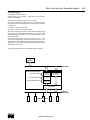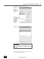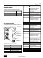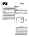
1
SERIAL BUS
DEVICENET™
ADAPTERS
RPSSCDM12A,
RPSSCDM18PA
User Manual 601
Important User Information
Important User Information
ATTENTION
Solid state equipment has operational characteristics differing from
those of electromechanical equipment. Safety Guidelines for the
Application, Installation and Maintenance of Solid State Controls
(Form #A10325) (available online at www.rosscontrols.com/rosslit.
htm), describes some important differences between solid state
equipment and hard-wired electromechanical devices. Because
of these differences, and also because of the wide variety of uses
for solid state equipment, all persons responsible for applying this
equipment must satisfy themselves that each intended application of
this equipment is acceptable.
In no event will ROSS CONTROLS® be responsible or liable for
indirect or consequential damages to persons or property resulting
from the use or application of this equipment.
The examples and diagrams in this manual are included solely
for illustrative purposes. Because of the many variables and
requirements associated with any particular installation, ROSS
CONTROLS cannot assume responsibility or liability for actual use
based on the examples and diagrams.
No patent liability is assumed by ROSS CONTROLS with respect
to use of information, circuits, equipment, or software described in
this manual.
Reproduction of the contents of this manual, in whole or in part, without
written permission of ROSS CONTROLS is prohibited.
Throughout this manual we use notes to make you aware of safety
considerations.
WARNING
!
Identifies information about practices or
circumstances that can cause an explosion in
a hazardous environment, which may lead to
personal injury or death, property damage, or
economic loss.
IMPORTANT
Identifies information that is critical for successful
application and understanding of the product.
ATTENTION
Identifies information about practices or
circumstances that can lead to personal injury
or death, property damage, or economic loss.
Attentions help you:
• Identify a Hazard
• Avoid a Hazard
• Recognize the Consequence
!
SHOCK HAZARD Labels may be located on or inside the
equipment to alert people that dangerous
voltage may be present.
BURN HAZARD
Labels may be located on or inside the
equipment to alert people that surfaces may be
dangerous temperatures.
!
Environment and Enclosure
This equipment is intended for use in overvoltage Category
II applications (as defined in IEC publication 60664-1), at
altitudes up to 2000 meters without derating. This equipment
is considered Group 1, Class A industrial equipment according
to IEC/CISPR Publication 11. Without appropriate precautions,
there may be potential difficulties ensuring electromagnetic
compatibility in other environments due to conducted as well as
radiated disturbance. This equipment is supplied as “enclosed”
equipment. It should not require additional system enclosure
when used in locations consistent with the enclosure type
ratings stated in the Specifications section of this publication.
Subsequent sections of this publication may contain additional
information regarding specific enclosure type ratings, beyond
what this product provides, that are required to comply with
certain product safety certifications.
NOTE: See NEMA Standards publication 250 and IEC
publication 60529, as applicable, for explanations of the
degrees of protection provided by different types of enclosures.
Also, see the appropriate sections in this publication, as well
as the publication A10324 (“Industrial Automation Wiring and
Grounding Guidelines”), for additional installation requirements
pertaining to this equipment.
ATTENTION
!
Preventing Electrostatic Discharge
This equipment is sensitive to electrostatic discharge, which
can cause internal damage and affect normal operation. Follow
these guidelines when you handle this equipment:
•Touch a grounded object to discharge potential static.
•Wear an approved grounding wrist strap.
•Do not touch connectors or pins on component boards.
•Do not touch circuit components inside the equipment.
•If available, use a static-safe workstation.
•When not in use, store the equipment in appropriate staticsafe packaging.
© 2007 ROSS CONTROLS®. All Rights Reserved.
Preface
1
Purpose of This Manual
This manual describes how to install, configure, and operate
your Serial Bus DeviceNet™ Adapters, catalog numbers
RPSSCDM12A and RPSSCDM18PA.
See the Following Sections:
Page:
Who Should Use This Manual
P-1
What the Manual Contains
P-2
Related Terms
P-3
Related Products and Documentation
P-4
Guidelines for Using Your Adapter
P-4
Conventions Used in This Manual
P-4
IMPORTANT
In this manual, we use Serial Bus DeviceNet adapters to refer
to all the DeviceNet™ adapter modules (RPSSCDM12A and
RPSSCDM18PA). We use the specific catalog number (e.g.,
RPSSCDM12A) to refer to a specific module.
In the rest of this manual (except Chapter 4), we refer to the
Serial Bus I/O DeviceNet™ adapters as the adapters.
In Chapter 4, we refer to the Serial Bus I/O DeviceNet adapter
as the scanner because the chapter describes how to configure
the adapter on the subnet.
Who Should Use This Manual
You must be able to use RSNetWorx for DeviceNet™ software, or
a similar configuration software, to configure your adapter.
In this manual, we assume you know how to configure an adapter.
If you do not, refer to your software user manuals, or online help,
before attempting to use these adapters.
We also assume you are familiar with the Serial Bus I/O product
line, including other serial bus interfaces, I/O modules, and power
supplies. If you are not familiar with these components, you can
read the Serial Bus I/O documents listed in the Related Products
and Documentation section.
www.rosscontrols.com
2
Preface
What the Manual Contains
This manual contains the following sections:
Chapter 1 - Install the Serial Bus DeviceNet Adapters
Description of how to install and wire the adapter
Chapter 2 - What Is the Serial Bus DeviceNet Adapter?
Overview of the adapter’s features and functionality
Male In Connector
RPSSCDM12A
DeviceNet Out
DeviceNet In
Adapter
Status
DeviceNet
Status
X1
X10
PointBus
Status
System
Power
Adapter
Power
PWR
Chapter 3 - Use Auto Start Mode
Or
Description of how to use the Auto Start Mode on your
adapter to quickly get your system up and running
Chapter 5 - Add the Serial Bus DeviceNet Adapter
to the DeviceNet Scanner’s Scanlist
Description of how to configure the DeviceNet adapter
and how to add it to the scanlist
Chapter
Chapter 4 - Configure the DeviceNet Scanner Subnet
Description of how to configure your
adapter on the subnet
Chapter 6 - Troubleshoot the
Serial Bus DeviceNet Adapter
Description of how to use the status indicators
and how to troubleshoot your adapter
5
Troubleshoot the Serial Bus
DeviceNet Adapter
This chapter describes how to custom configure your adapter
for use with DeviceNet devices.
This chapter describes how to troubleshoot your adapter.
Indication
DeviceNet Status
Off
See the Following Sections:
See the Following Sections:
Page:
Configuration Overview
5-1
5-2
5-4
Chapter Summary
5-4
Page:
Use the Status Indicators
5-1
Add the Adapter to Your Network
Set the Adapter's Parameters
Go On Line
6-1
Guidelines for Using Your Adapter
6-2
Chapter Summary
6-2
Flashing Green
Green
Flashing Red
Red
Your adapter works on two networks simultaneously and must
be configured for each separately, which means that you will
have two separate RSNetWorx for DeviceNet software files.
This chapter explains configuration of the adapter for use on the
primary DeviceNet network. For information on how to configure
the adapter for use on the Subnet, see Chapter 4, Configure the
DeviceNet Scanner Subnet.
Use the Status Indicators
You can use the status indicators to troubleshoot your adapter. The
following graphic shows the adapter’s status indicators.
Indication
PointBus Status
Off
RPSSCDM18PA
Flashing Green
Configuration Overview
Add the Adapter to Your Network
You must use the RSNetWorx for DeviceNet software to configure
your adapter. You can configure the adapter while it is:
Follow these steps:
Green
PSSCDM18PA
DNet
Out
Adapter Status
Indicator
DNet
In
1. Start the RSNetWorx for DeviceNet software.
2. Add the adapter as shown below.
On line
DeviceNet Status
Indicator
Adapter
Status
Off line
This chapter shows configuration in the offline mode. Configuration
screens appear the same in both modes. Note that some screen
options are unavailable in offline mode. The only difference is that if
you make changes off line, you must take the adapter on line
before the configuration changes take effect.
You must follow these steps during configuration:
1. Add the adapter to your network
2. Set the adapter’s parameters
DeviceNet
Status
1. Expand
the list of
communication
adapters.
X10
Flashing Red
Red
PointBus Status
Indicator
PointBus
Status
X1
System
Power
Adapter
Power
PWR
2. To add the
adapter, you
can double click
on the adapter,
or click and drag
the adapter
name onto
the network.
System Power
Indicator
Flashing Red/Green
Adapter Power
Indicator
Indication
System Power
Off
Use the table below to troubleshoot your adapter.
Indication
Adapter Status
Off
Green
Flashing Red
Red
3. Add the DeviceNet adapter’s scanlist (see the Quick Start,
Appendix B)
4. Go on line
Flashing Red/Green
Probable Cause
Green
No power applied to device
Device operating normally
Recoverable fault
Unrecoverable fault may require device replacement
Device is in self-test
Indication
Adapter Power
Off
Green
Probable Cause
Device is not on line:
- Device attempting to Autobaud
- Device has not completed
dup_MAC-id test
- Device not powered - check module
status indicator
Device is on line but has no
connections in the established state
Device is on line and has
connections in the established state
One or more I/O connections in
timed-out state
Critical link failure - failed
communication device. Device
detected error that prevents it from
communicating on the network.
(Possible duplicate MAC ID or baud
rate mismatch).
Probable Cause
Device is not on line:
- Device has not completed
dup_MAC-id test
- Device not powered - check module
status indicator
Device is on line but has no
connections in the established state
Device is on line and has
connections in the established state
One or more I/O connections in
timed-out state
Critical link failure - failed
communication device. Device
detected error that prevents it from
communicating on the network.
(Possible duplicate MAC ID or baud
rate mismatch).
Communication faulted device - the
device has detected a network access
error and is in communication faulted
state. Device has received and accepted
an Identity Communication Faulted
Request - long protocol message.
Probable Cause
Not active - Field power is off or
dc-dc converter problem.
System power on - dc-dc converter
active (5V).
Probable Cause
Not active - Field power is off.
System power on, 24V present.
Publication A10311 – April 2007
Appendix A - Specifications
Listing of the Serial Bus adapters’ specifications
Appendix
Publication A10311– April 2007
Appendix B - Default Data Maps
Listing of the default data maps for Serial Bus I/O modules
A
Specifications
6
Chapter
Add the Serial Bus DeviceNet Adapter to
the DeviceNet Scanner's Scanlist
B
Appendix
Default Data Maps
Following are specifications for the DeviceNet adapters.
DeviceNet Adapters - RPSSCDM12A, RPSSCDM18PA
Expansion I/O Capacity
DeviceNet adapter backplane current output = 1.0A maximum.
See the list below for backplane current consumption for each I/O catalog number and
the current consumption for each of the modules connected to the DeviceNet adapter.
Verify that it is below 1.0A.
Backplane current can be extended beyond 1.0A with a PSSSE24A Backplane
Extension Power Supply. The PSSSE24A can supply up to an additional 1.3A of
backplane current.
Multiple PSSSE24A modules can be used to reach the
maximum of 63 modules.
I/O messages are sent to (consumed) and received from
(produced) the IsysNet I/O modules. These messages are
mapped into the processor’s memory. This appendix lists the
default data maps for 1738 IsysNet I/O modules.
For the Default Data Map of:
See Page:
PSSN8 Sink Input Module
B-1
PSSP8 Source Input Module
B-1
PSST8 Electronically Protected Output Module
DeviceNet Communication Rate
DeviceNet Power Specifications
Power Supply
Input Voltage Rating
DeviceNet Input Voltage Range
Input Overvoltage Protection
DeviceNet Power Requirements
Power Supply Specifications
Power Supply
Input Voltage Rating
Input Overvoltage Protection
Inrush Current
PointBus Output Current
Field Side Power Requirements, Maximum
Interruption
General Specifications
LED Indicators
Cat. No.
RPSSN8xxx
RPSSP8xxx
RPSST8xxx
RPSSTR4M12A
RPSSNA
RPSSNAVM12A
RPSSTACM12A
RPSSTAVM12A
RPSSS23A
RPSSV32A
125K bit/s (500m maximum)
250K bit/s (250m maximum)
500K bit/s (100m maximum)
PSSTR4 Relay Sink/Source Output Module
PointBus Current Requirements
75 mA
75 mA
75 mA
90 mA
75 mA
75 mA
75 mA
75 mA
75 mA
75 mA
Note: In order to comply with CE Low Voltage Directives (LVD), you must use either a
NEC Class 2, a Safety Extra Low Voltage (SELV) or a Protected Extra Low Voltage (PELV)
power supply to power this adapter. A SELV supply cannot exceed 30V rms, 42.4V peak
or 60VDC under normal conditions and under single fault conditions. A PELV supply has
the same rating and is connected to protected earth.
24VDC nominal
11-25VDC DeviceNet specification
Reverse polarity protected
24VDC (+4% = 25VDC) @ 30 mA maximum
Note: In order to comply with CE Low Voltage Directives (LVD), you must use either a
NEC Class 2, a Safety Extra Low Voltage (SELV) or a Protected Extra Low Voltage (PELV)
power supply to power this adapter. A SELV supply cannot exceed 30V rms, 42.4V peak
or 60VDC under normal conditions and under single fault conditions. A PELV supply has
the same rating and is connected to protected earth.
24VDC
10-28.8VDC range
Reverse polarity protected
6A maximum for 10ms
1A maximum @ 5VDC +5% (4.75-5.25)
24VDC (+20% = 28.8VDC) @ 400 mA
Output voltage will stay within specifications when input drops out for
10ms at 10V with maximum load
B-2
B-3
PSSTAC Analog Current Output Module
B-3
PSSTAV Analog Output Module
B-4
PSSS23A ASCII Module
B-4
RPSSN8 Sink Input Module
Message size: 1 Byte
Produces (scanner Rx)
7
6
5
Ch7
Ch6
Ch5
Consumes (scanner Tx)
4
3
2
1
0
Ch4
Ch3
Ch2
Ch1
Ch0
No consumed data
Where: Ch0 = input channel 0, Ch1 = input channel 1, Ch2 = input channel 2, Ch3 = input channel 3, Ch4 = input channel 4, Ch5 = input channel 5,
Ch6 = input channel 6, Ch7 = input channel 7; 0 = OFF, 1 = ON
RPSSP8 Sour
ce Input Module
Message size: 1 Byte
Produces (scanner Rx)
1 green/red Adapter status
1 green/red DeviceNet status
1 green/red PointBus status
1 green System Power (PointBus 5V power)
1 green Adapter Power (24V from field supply)
B-2
B-2
PSSNAC Analog Current Input Module
PSSNAV Analog Input Module
Consumes (scanner Tx)
7
6
5
Ch7
Ch6
Ch5
4
3
2
1
0
Ch4
Ch3
Ch2
Ch1
Ch0
No consumed data
Where: Ch0 = input channel 0, Ch1 = input channel 1, Ch2 = input channel 2, Ch3 = input channel 3, Ch4 = input channel 4, Ch5 = input channel 5,
Ch6 = input channel 6, Ch7 = input channel 7; 0 = OFF, 1 = ON
Publication A10311 – April 2007
© 2007 ROSS CONTROLS®. All Rights Reserved.
Publication A10311 – April 2007
Preface
3
Related Terms
This manual uses the following terms:
Term
Adapter
Auto
Catalog
Replace
Auto
Device
Replacement
(ADR)
Auto
Start
Mode Autobaud
Backplane
Baudrate
Change
of State
(COS)
Commissioning
ControlFlash™
Definition
The adapter interfaces between DeviceNet
devices and Serial Bus I/O modules. Serial Bus
I/O DeviceNet adapters include the
RPSSCDM12A and RPSSCDM18PA.
The Serial Bus I/O DeviceNet adapter supports
the swapping of two identical modules connected
to the adapter. That is, if a RPSSN8M8A is in slot 3 and another RPSSN8M8A is in slot 7, the two
modules can be removed from the Serial Bus
system and the slot 3 module placed into slot 7,
and vice-versa. When Automatic Device
Replacement (ADR) is active, the swapped
modules will be reconfigured to match the
previous module in their new slot. When ADR is
not active, the configuration parameters will not
be modified, the swapped modules must have
identical configuration and values for their EDS
file parameters.
This refers to the ADR feature of a ControlLogix
System on DeviceNet. With ADR active, any
device on the DeviceNet link may be removed
and replaced with an out-of-the-box checkmark
compliant DeviceNet device. The ADR feature
will result in downloading the values of the
configuration parameters of the EDS file of the
removed device to the new device.
A feature that lets the Serial Bus I/O system get “up any of the EDS parameters for the PointBus™
or Serial Bus I/O modules. Using Auto Start Mode will result in a scan list within the adapter that stores the modules identity information.
A feature in devices (e.g., Serial Bus I/O modules) on the DeviceNet network that causes them to listen to communications on the network and set their own baudrate to match the network rate.
The PointBus that consists of Serial Bus I/O modules connected to the Serial Bus DeviceNet adapter.
Rate of communications between devices on the
DeviceNet network. Backplane baudrate is used
for the RPSSCMD12A and RPSSCDM18PA.
DeviceNet communications method in which the
adapter sends data based on detection of any
changed value within the input data. Data is
independently received based on a change of
state from the sender. Data in both directions can
be acknowledged or unacknowledged depending
on the run-time configuration of the system.
The period in time associated with post startup
activities. Commissioning implies that the
system has been validated and all configuration
parameters are correct, all modules are in
good operating condition, and the adapter
scanlist is complete.
Utility software you can use to update the
adapter’s firmware with the most current boot
and application code.
Term
Definition
Cyclic
DeviceNet communications method in which
the adapter sends data cyclically based on a
configured time value. Data is independently
received cyclically from the sender. Data in
both directions can be acknowledged or
unacknowledged depending on the run time
configuration of the system.
MACID
Media Access Control Identifier
(DeviceNet network address).
Master
A DeviceNet network device (e.g., Rockwell
Automation 1771-SDN) that initiates
communication with DeviceNet slave devices
(e.g., Serial Bus I/O modules) to retrieve data.
The master only receives unprompted data
when the slave is enabled for COS and there
is a change in the device’s operating state.
Offline
State of the adapter when it is not powered or
maintaining normal communication exchanges
with other DeviceNet devices.
Online
State of the adapter when it is powered and
maintaining normal communication exchanges
with other DeviceNet devices.
PointBus
The Serial Bus I/O backplane PointBus maintains all DeviceNet network protocol, but also offers configuration capabilities.
Polled
DeviceNet communications method in which
a module sends data in response to
received data.
Primary
Network
The primary DeviceNet network is defined as
the DeviceNet link that provides the direct
connection between the Serial Bus DeviceNet
adapter and a DeviceNet scanner.
RSNetWorx for
DeviceNet
Configuration software for the adapter and
Subnet modules.
Scanlist
The list of Subnet modules connected to the
adapter. When ADR is active, the scanlist
stores the configured values of each of the
Subnet modules’ configurable parameters.
When ADR is not active, the scanlist stores
only the module identity information.
Scanner
Operating state of the Serial Bus DeviceNet
adapter when it retrieves I/O data from
Subnet modules.
Slave
A DeviceNet network device that cannot initiate
communication (except when configured with
COS enabled) but responds to a DeviceNet
master device.
Strobe
Adapter sends data in response to the strobe
command. The single bit allocated to the
adapter in the strobe message is not used.
If the configured size of the input data (sent
from the adapter) is greater than 8 bytes, the
strobe connection establishment will fail. In this
case, the input size must be reconfigured to
8 bytes or less.
www.rosscontrols.com
4
Preface
Related Products and Documentation
The following table lists related Serial Bus I/O products and
documentation:
Description
Model Number
Publication
Serial Bus 32 Point Valve Driver Installation Instructions
RPSSV32A
A10312
Serial Bus DeviceNet Adapters Installation Instructions
RPSSCDM12A, RPSSCDM18PA
A10313
Serial Bus PROFIBUS Adapter Installation Instructions
RPSSCPBA
A10314
Serial Bus ControlNet Adapter Installation Instructions
RPSSCCNA
A10315
Serial Bus EtherNet/IP Adapter Installation Instructions
RPSSCENA
A10316
Serial Bus I/O 24VDC Expansion Power Supply Installation Instructions
RPSSSE24A
A10317
Serial Bus 24VDC Input Modules Installation Instructions
RPSSN8, RPSSP8
A10318
Serial Bus 24VDC Output Modules Installation Instructions
RPSST8
A10319
Serial Bus Relay Output Modules Installation Instructions
RPSSTR4M12A
A10320
Serial Bus 24VDC Analog Input Modules Installation Instructions
RPSSNA
A10321
Serial Bus 24VDC Analog Output Modules Installation Instructions
RPSSTA
A10322
Serial Bus RS232 ASCII Module Installation Instructions
RPSSS23A
A10323
Industrial Automation Wiring and Grounding Installation Instructions
N/A
A10324
Safety Guidelines for the Application, Installation and Maintenance of Solid State Control
N/A
A10325
If you need more information on these products, contact your local
distributor, integrator or sales office for assistance.
Guidelines for Using Your Adapter
Conventions Used In This Manual
Remember the following operational guidelines when using your
Serial Bus DeviceNet adapter.
The following conventions are used throughout this manual:
• Do not leave spaces in the I/O. Instead, install all Serial Bus
I/O modules adjacent to each other.
• Populate every position on the mounting base.
• Serial Bus does not support removal and insertion under
power (RIUP). When an I/O module is removed, the IP67 seal
is broken and the backplane bus is interrupted.
• Bullet lists (such as this one) provide information, not
procedural steps
• Numbered lists provide sequential steps
• Text written like this identifies screen, menu, toolbar names,
field names, buttons, and check boxes on screens
• A menu item in this format File>Save identifies the submenu
item after the caret (>) that is accessed from the main menu
(name before the caret)
• Pictures of symbols and/or screens represent the actual
symbols you see or the screens you use
© 2007 ROSS CONTROLS®. All Rights Reserved.
Table of Contents
i
Chapter 1
Install the Serial Bus
Mount the Adapter and I/O Base ................................................................. 1-1
DeviceNet Adapters
Set the Node Address ................................................................................. 1-1
Wire the DeviceNet Adapters ...................................................................... 1-2
RPSSCDM12A ...................................................................................... 1-2
RPSSCDM18PA .................................................................................... 1-2
DeviceNet Auxiliary Power .................................................................... 1-2
Chapter Summary and What’s Next ............................................................ 1-2
Chapter 2
What Is the Serial Bus
Use the Adapter . ......................................................................................... 2-1
DeviceNet Adapter?
Set Subnet/Backplane Baudrate ........................................................... 2-2
Set Subnet/Backplane I/O Module Addresses ...................................... 2-2
Configure the Subnet I/O ...................................................................... 2-2
Configure the Primary DeviceNet Network ........................................... 2-2
Remove and Reinsert Modules on the Backplane ................................ 2-2
Understand the DeviceNet Network and Subnet ......................................... 2-3
DeviceNet Network ............................................................................... 2-3
Backplane/Subnet Network ................................................................... 2-3
Adapter Features ......................................................................................... 2-4
Communicate Through the Adapter . ........................................................... 2-8
Map the Data . ....................................................................................... 2-8
Overview of the Communication Process ............................................. 2-8
Image Table Mapping ............................................................................ 2-9
Communicate With I/O Modules ................................................................ 2-10
Use Diagnostic Tables ............................................................................... 2-11
Chapter Summary and What’s Next .......................................................... 2-12
Chapter 3
Use Auto Start Mode
Why Use Auto Start Mode? ......................................................................... 3-2
What Does Auto Start Mode Do? .......................................................... 3-2
How Is I/O Data Mapped Using Auto Start Mode? . .............................. 3-2
Requirement To Using Auto Start Mode ................................................ 3-2
Install the I/O Module . ................................................................................. 3-3
Remove the Module From the Mounting Base ...................................... 3-3
Use RSNetWorx for DeviceNet .................................................................... 3-4
Begin Auto Start Mode ................................................................................ 3-5
Use Custom Configuration . ......................................................................... 3-6
Chapter Summary and What’s Next ............................................................ 3-6
www.rosscontrols.com
ii
Table of Contents
Chapter 4
Configure the DeviceNet
Configuration Overview ............................................................................... 4-1
Scanner Subnet
Add the Scanner To Your Network ......................................................... 4-1
Add I/O Modules To Your Network ......................................................... 4-1
Set the Scanner’s Parameters . ............................................................. 4-2
Go On Line ............................................................................................ 4-6
Chapter Summary and What’s Next ............................................................ 4-6
Chapter 5
Add the Serial Bus DeviceNet
Configuration Overview ............................................................................... 5-1
Adapter to the DeviceNet
Add the Adapter to Your Network .......................................................... 5-1
Scanner’s Scanlist
Set the Adapter’s Parameters ............................................................... 5-2
Go On Line ............................................................................................ 5-4
Chapter Summary ....................................................................................... 5-4
Chapter 6
Troubleshoot the Serial Bus
Use the Status Indicators ............................................................................ 6-1
DeviceNet Adapter
Guidelines for Using Your Adapter ............................................................... 6-2
Chapter Summary ....................................................................................... 6-2
Appendix A
Specifications
Appendix B
Default Data Maps
RPSSN8 Sink Input Module ........................................................................B-1
RPSSP8 Source Input Module ....................................................................B-1
RPSST8 Electronically Protected Output Module .......................................B-2
RPSSTR4 Relay Sink/Source Output Module .............................................B-2
RPSSNAC Analog Current Input Module ....................................................B-2
RPSSNAV Analog Input Module . ................................................................B-3
RPSSTAC Analog Current Output Module ..................................................B-3
RPSSTAV Analog Output Module . ..............................................................B-4
RPSSS23A ASCII Module ...........................................................................B-4
RPSSV32A 32 Point Valve Driver Module ...................................................B-4
© 2007 ROSS CONTROLS®. All Rights Reserved.
1
Chapter
Install the Serial Bus DeviceNet
Adapters
Mount the Adapter and I/O Base
This chapter describes how to install and wire your adapter.
See the Following Sections:
Page:
Mount the Adapter and I/O Base
1-1
Set the Node Address
1-1
Wire the DeviceNet Adapters
1-2
Chapter Summary and What’s Next
1-2
1.9
(47.2)
To mount the Serial Bus adapter on a wall or panel, use the screw
holes provided in the adapter.
2.0
(50)
0.87
(22)
A mounting illustration for the Serial Bus adapter with I/O bases is
shown below.
Install the Mounting Base as Follows:
1.Lay out the required points as shown in the drilling dimension
drawing.
2.Drill the necessary holes for #8 (M4) machine or self-tapping
screws.
3.Mount the adapter and I/O bases using #8 (M4) screws.
4.Ground the system using the ground lug connection in the I/O
base. (The ground lug connection is also a mounting hole.)
2.0
(50)
3.13
(79.4)
5.98*
(151.9)
Adapter
2.39
(60.7)
4.02
(102)
4.32
(109.8)
1.81
(46)
Inches
(mm)
Drill and Tap
for M4 Screw
3.02
(76.6)
5.39
(137.0)
Drill and Tap
for M6 Screw
*Depending on the type and number of manifolds, this dimension
may vary. Refer to Bulletin A10309 for additional information.
Set the Node Address
Valid node addresses are 00 through 63.
Set the node address using either the rotary switches, RSNetWorx for
DeviceNet™, DeviceNetManager™, or another software configuration
tool. Setting the switches at any number from 64 through 99 lets the
software have address control.
Each module is shipped with the switches set for node address
63. Remove the caps on the front of the module to access the
switches (refer to the X10 and X1 on the front of the module). The
two switches are:
• X10 (most significant digit) – left side of module
• X1 (least significant digit) – right side of module
To reset the node address, use a small blade screwdriver to rotate
the switches. Line up the small notch on the switch with the number
setting you wish to use and then cycle power.
The rotary switches are read periodically. If the switches have been
changed since the last time they were read and they no longer match
the on line address, a minor fault will occur, which is indicated by a
flashing red Adapter Status LED. Settings of 64 through 99 cause
the module to use the last valid node address stored internally.
For example, the last setting internally was 40. If a change is made
to 68, and then you power up, the address will default to 40.
The module is equipped with AutoBaud detect. AutoBaud lets the
module read the settings already in use on your DeviceNet network
and automatically adjusts to follow those settings.
This example shows the
node address set at 63.
www.rosscontrols.com
1-2
Install the Serial Bus DeviceNet Adapters
Wire the DeviceNet Adapters
Following are wiring instructions for the DeviceNet Adapters.
RPSSCDM12A
Male In Connector
Female Out Connector
(view into connector)
Pin 1-Drain
Pin 2-+V
Pin 3--V
Pin 4-CAN_High
Pin 5-CAN_Low
RPSSCDM18PA
Female Out Connector
Male In Connector
(view into connector)
Pin 1-Drain
Pin 2-+V
Pin 3--V
Pin 4-CAN_High
Pin 5-CAN_Low
DeviceNet Auxiliary Power
Male In Connector
(view into connector)
Pin 1-User Power +
Pin 2-Adapter Power +
Pin 3-Adapter Power Pin 4-User Power -
ATTENTION
Chapter Summary and What’s Next
!
Make sure all connectors and caps are securely tightened to
properly seal the connections against leaks and maintain IP67
requirements.
In this chapter, you learned how to install and wire your
DeviceNet adapter. Move to Chapter 2 to learn about
the Serial Bus DeviceNet adapters.
© 2007 ROSS CONTROLS®. All Rights Reserved.
Chapter
What Is the Serial Bus DeviceNet
Adapter?
Use the Adapter
The adapter resides on the primary DeviceNet network and the
Subnet simultaneously.
This chapter describes the Serial Bus I/O DeviceNet
adapter, including descriptions of the adapter’s features and
functionality.
See the Following Sections:
Page:
Use the Adapter
2-1
Understand the DeviceNet Network
and Subnet
2-3
Adapter Features
2-4
2
IMPORTANT
The PointBus maintains all DeviceNet network protocol, but also
offers configuration capabilities.
The adapter interfaces between DeviceNet devices and Serial Bus
I/O modules. The graphic below shows the adapter on the DeviceNet
network and PointBus.
Communicate Through the Adapter
2-8
Communicate With I/O Modules
2-10
Use Diagnostic Tables
2-11
Chapter Summary and What’s Next
2-12
Computer with PLC
Programming Software
ControlNet Network
ControlLogix
Chassis
1784-PCD
PCMCIA
Card
Computer with
RSNetWorx for
DeviceNet Software
DeviceNet Network
Serial Bus I/O Modules
PSSN8M12A
24V dc In
PSSCDM12A
0
2
1
3
PSST8M12A
24V dc Out
0
2
1
3
PSSV32A
DeviceNet Out
Adapter
Status
See page 2-8 for an
explanation of the
number sequence.
RPSSCDM12A
Adapter
DeviceNet In
0
2
8
6
x10
4
MOD
DeviceNet
Status
PointBus
Status
0
2
8
6
4
x1
System
Power
Adapter
Power
MOD
NET
4
6
7
Net
0
1
1
2
2
3
3
4
6
4
5
Mod
NET
0
5
Fault
4
5
7
5
6
6
7
7
PWR
After you have installed your adapter into a Serial Bus I/O system,
you must perform the following tasks:
1.Set Subnet/Backplane Baudrate
2.Set Subnet/Backplane I/O Module Addresses
3.Configure the Subnet I/O
4.Configure the Primary DeviceNet Network
The steps mentioned above are explained briefly here, and then
in greater detail throughout this manual. You must complete the
steps for the adapter to work with DeviceNet masters (e.g. Rockwell
Automation 1756-DNB) on the primary network and Subnet
modules.
www.rosscontrols.com
2-2
What is the Serial Bus DeviceNet Adapter?
1.Set Subnet/Backplane Baudrate
Remove and Reinsert Modules on the Backplane
The adapter and Subnet/Backplane modules must use the same
baudrate to communicate with each other. Use one or both of the
following to set a Subnet/Backplane baudrate.
• Set the adapter baudrate for the Subnet. The default for the
RPSSCDM12A and RPSSCDM18PA is 1Mbaud.
Removal and Insertion Under Power (RIUP) is not recommended in
a Serial Bus System because of the following reasons.
• Removing a module breaks the IP67 seal.
• Removing a module breaks the backplane bus. Modules to
the right of the removed module will be ‘lost’ to the adapter.
Also, the terminating resistor will be removed, causing system
uncertainty.
• Inserting a module under power may cause the adjacent
module to reset due to the addition of a large capacitive load
on the power bus.
You set the backplane baudrate for the RPSSCDM12A and
RPSSCDM18PA.
• Enable or disable the Backplane Autobaud feature for Serial
Bus I/O modules. Serial Bus I/O modules have Autobaud
enabled as the default - See page 2-5.
2. Set Subnet/Backplane I/O Module Addresses
IMPORTANT
If the module is removed while it is under power, all the modules
to the right of the removed module will disconnect from the
PointBus and field power until the module is reinstalled.
4.Configure the Primary DeviceNet Network
If you must remove and reinsert modules, we recommend the
following:
• Do not move I/O modules to different locations on the mounting
base after they have been installed and configured.
• If adjacent modules (i.e., 2 or more) are removed from the
backplane, replace all of them before attempting to operate
the Serial Bus I/O system. Input data will hold last state until
all previously removed modules are replaced.
– If adjacent modules are removed and all but one is
returned, the adapter cannot verify the location of the
returned modules. For example, if modules are removed
from nodes 3 and 4 and only the module from node 4 is
returned, the adapter cannot verify the location. In this
case, the adapter alerts you via a flashing red PointBus
status LED that it cannot verify the presence of modules in
the affected locations. I/O data will not be exchanged with
this node until both modules have been reinserted.
– If modules of different types are removed and returned
to the wrong locations, the adapter identifies the returned
modules and alerts you (via RSNetWorx for DeviceNet) that
the error has occurred and must be corrected.
– If modules of the same type are removed and returned
to the wrong locations, the adapter identifies the
returned modules, updates their MACIDs, and continues
operation.
Finally, you must configure the adapter for communication with a
master (e.g., Rockwell Automation 1756-DNB).
IMPORTANT
The removal and return scenario exists whether the system is
under power or not. If the system is under power, the scenario
arises immediately. If the system is not under power, the
scenario arises in the next power cycle.Also, the example above
shows removal of two adjacent modules. The scenario described
exists anytime 2 or more adjacent modules are removed and
all are not returned.
IMPORTANT
Care must be taken when replacing backplane I/O modules.
Each I/O module stores its configuration parameters in internal
non-volatile memory. You must either enable ADR for all modules
or manually configure each module in a non-manufacturing
environment when the module is being replaced or placed on
the network for the first time. Failure to do so could result in
inadvertent control attributed to different configuration settings.
Once the adapter and Serial Bus I/O modules are communicating
at the same rate on the backplane, you must make sure all modules
use a valid MACID.
Set the Auto Address feature for Serial Bus I/O modules - See
page 2-5.
3.Configure the Subnet I/O
In the first two steps, you set a consistent communication rate and
made sure each module uses valid addresses for communication.
Next you must configure the PointBus (e.g., set scan list).
You can configure the PointBus using one of two methods:
• Auto Start Mode (ASM) or
• Manually For more information on configuring the PointBus,
see Chapter 3 for ASM or see Chapter 4 for manual
configuration.
For more information on configuring the DeviceNet network, see
Chapter 5, Add the Serial Bus DeviceNet Adapter to the DeviceNet
Scanner’s Scanlist.
You must understand all of the adapter’s features to effectively use
it in your Serial Bus I/O system. Keep these four steps in mind as
you read this manual:
1.Set Subnet/Backplane Baudrate
2.Set Subnet/Backplane I/O Module Addresses
3.Configure the Subnet I/O
4.Configure the Primary DeviceNet Network
© 2007 ROSS CONTROLS®. All Rights Reserved.
What is the Serial Bus DeviceNet Adapter?
Understand the DeviceNet
Network and Subnet
2-3
Backplane / Subnet Network
On the Backplane/Subnet, your adapter acts as a scanner and is the
master of the Subnet modules. The adapter performs the following
functions:
DeviceNet Network
Your adapter serves as a slave to DeviceNet masters. The adapter
receives data from, and returns data to, the master through the
following I/O connections:
• Exchanges I/O data with devices on the Backplane/Subnet
• Collects I/O data from the Backplane/Subnet and sends
it to devices on the DeviceNet network (e.g., scanners or
controllers)
• Supplies power to the backplane I/O modules (See Appendix
A for power supply rules regarding I/O modules power
requirements.)
• Change of State (COS)
• Cyclic
• Polled
• Strobe
Data Collection
The adapter collects I/O data from up to 63 modules via the
Backplane/Subnet. The I/O modules appear on the primary
DeviceNet network as a single node, though, and require only one
DeviceNet node address.
IMPORTANT
If Automatic Device Replacement (ADR) is enabled on the
adapter, you can only connect up to 62 modules via the
Subnet.
For more information on ADR, see page 2-6.
Module Power
The adapter supplies 5V logic power to Serial Bus I/O modules by
converting 24VDC field power to PointBus 5V power.
You can connect up to 63 I/O modules to each adapter and you can
power the backplane I/O modules from the adapter (with a maximum
of 10A of field power). You may use the integrated, isolated 24VDC
expansion power unit (RPSSSE24A) to power additional I/O modules,
as shown below.
RPSSCDM12A
Adapter
RPSSN8M12A
24V dc In
RPSSCDM12A
0
2
1
3
RPSSSE24A
Expansion
Power Unit
Serial Bus I/O
Modules
RPSST8M12A
24V dc Out
0
2
1
3
RPSSN8M12A
24V dc In
0
2
1
3
RPSST8M12A
24V dc Out
0
2
1
3
RPSSN8M12A
24V dc In
0
2
1
3
RPSST8M12A
24V dc Out
RPSSSE24A
24V dc Power Supply
0
2
1
3
RPSSV32A
32 Point
Valve Driver
Serial Bus I/O
Modules
RPSSN8M12A
24V dc In
0
2
1
3
RPSST8M12A
24V dc Out
0
2
1
3
RPSSN8M12A
24V dc In
0
2
1
3
RPSST8M12A
24V dc Out
0
2
1
3
RPSSN8M12A
24V dc In
0
2
1
3
RPSST8M12A
24V dc Out
0
2
1
3
Valves
RPSSV32A
DeviceNet Out
Adapter
Status
DeviceNet In
MOD
DeviceNet
Status
PointBus
Status
MOD
NET
0
0
2
6
x10
4
2
8
6
4
x1
System
Power
Adapter
Power
6
3
6
5
7
5
3
6
5
7
5
3
6
5
7
5
3
6
5
7
5
FIELD
POWER
3
6
5
7
5
6
6
6
6
6
7
7
7
7
7
3
6
5
7
5
3
6
5
7
5
3
6
5
7
5
3
6
5
7
5
3
6
5
7
5
3
7
5
Fault
2
4
6
4
5
Mod
1
2
4
4
Net
0
1
2
4
4
NET
0
1
2
4
4
MOD
NET
0
1
2
4
4
MOD
NET
0
1
2
4
4
P
AO
UW
XE
R
MOD
NET
0
1
2
4
4
MOD
NET
0
1
SYSTEM
POWER
2
4
4
MOD
NET
0
1
2
4
4
MOD
NET
0
1
2
4
4
MOD
NET
0
1
2
4
4
MOD
NET
0
1
2
4
MOD
NET
0
1
0
8
MOD
NET
3
4
5
7
5
6
6
6
6
6
6
6
7
7
7
7
7
7
7
PWR
For more information on the RPSSSE24A expansion power unit,
see the Serial Bus I/O 24VDC Expansion Power Supply Installation
Instructions, publication A10317.
www.rosscontrols.com
2-4
What is the Serial Bus DeviceNet Adapter?
Adapter Features
Baudrates
Your adapter uses the following features on both the DeviceNet
network and the PointBus:
Choose baudrates for the adapter in the RSNetWorx for DeviceNet
software. The adapter supports these rates:
• Self-Test
• 125Kbaud
• Field Upgradable Firmware
• 250Kbaud
• 500Kbaud
• Fully Configurable Software
• Autobaud – The adapter detects the primary DeviceNet
network baudrate and automatically sets its own baudrate to
match the network.
• Connections
• Baudrates
• For the RPSSCDM12A and RPSSCDM18PA, the PointBus
can be configured to operate at 1Mbaud (1000Kbaud).
Self-Test
When power is applied to the adapter, the adapter performs a selftest. The adapter tests various internal and programmatic memories
and checks the status indicators (LEDs).
Field Upgradable Firmware
You can update the adapter’s firmware with the ControlFlash
Utility software. This feature lets you always use the most current
firmware.
Fully Software Configurable
The adapter is fully software configurable using RSNetWorx for
DeviceNet. You must configure the adapter to be used with a
DeviceNet master (e.g. 1756-DNB) and separately to be used with
Subnet devices.
For more information on how to configure your adapter to use with
a DeviceNet master, see Chapter 5, Add the Serial Bus DeviceNet
Adapter to the DeviceNet Scanner’s Scanlist.
For more information on how to configure your adapter to use with
Subnet modules, see Chapter 4, Configure the DeviceNet Scanner
Subnet.
Connections
Your adapter supports the following connections on both the primary
DeviceNet network and Subnet:
Auto Start Mode
Auto Start Mode lets you easily get your adapter installed and
operating. In this mode, the adapter’s configurable features operate
as they were most recently configured. For example, if Autobaud on
DeviceNet was enabled in the adapter’s last configuration, it will be
enabled when Auto Start Mode is used.
For a more detailed explanation of how to use Auto Start Mode, see
Chapter 3.
Auto Catalog Replace
Auto Catalog Replace corrects errors that might occur when
backplane modules of the same type are removed and replaced in
the wrong location. If modules of the same type are removed and
returned to the wrong locations, the adapter identifies the returned
modules, updates their MAC IDs, and continues operation.
IMPORTANT
If modules of different types are removed and returned to the
wrong locations, the adapter identifies the returned modules
and alerts you (via RSNetWorx for DeviceNet, the Node Status
Table, and the Faulted Node Table) that the error has occurred
and must be corrected.
Backplane (RPSSCDM12A and RPSSCDM18PA) Baudrate
EDS parameter Backplane Baudrate is accessible from the primary
DeviceNet and sets a specific baudrate for all backplane I/O
modules.
• I/O connections:
– Polled
Set this parameter in RSNetWorx for DeviceNet to one of the
following baudrates:
– Strobe
– Cyclic
– COS
• 125 Kbaud
• Explicit connections
• 250 Kbaud
You can use I/O mapping to determine the data contained in each
connection.
The adapter supports Master/Slave connection types on the
DeviceNet network. On the Subnet, the adapter functions as a
scanner device, exchanging data with I/O modules.
• 500 Kbaud
• 1 Mbaud (available for both Serial Bus DeviceNet adapters)
When you download this parameter, the adapter sends a command
to reset all present I/O modules on the backplane to the new
baudrate. If additional modules are connected to the adapter, you
must download the Backplane/Subnet Baudrate to make sure the
new modules use the same rate as the others.
© 2007 ROSS CONTROLS®. All Rights Reserved.
What is the Serial Bus DeviceNet Adapter?
The baudrate may not take effect until power is recycled or the I/O
modules are reset.
IMPORTANT
Changes to the Backplane Baudrate parameter only take effect if
they are downloaded on an individual basis. (For example, if you
change the Backplane Baudrate and download the changes with
additional changes to other features, the Backplane Baudrate
remains at the previous setting.)
Also, this parameter should be set to ‘Do Nothing’ when
you download all parameters, or when Automatic Device
Replacement is enabled for the adapter.
If you want to set an I/O module to use a specific baudrate (i.e.,
125, 250, 500), you must first disable Backplane Autobaud for
that module.
Backplane Baudrate performs the following functions:
• Sets the adapter’s Subnet baudrate
• Sends a message to all connected backplane I/O modules.
If an I/O module is set to autobaud, it receives the message,
but ignores the new baudrate.
Backplane Autobaud
The adapter itself never autobauds on the Subnet. Backplane
Autobaud automatically enables or disables Autobaud for all I/O
modules currently attached to the backplane. The adapter does not
set a specific rate though (as with Backplane Baudrate).
If you enable Backplane Autobaud in the adapter or the EDS
parameter access that you set from the primary DeviceNet, the
adapter only enables the Autobaud in all backplane I/O modules.
When the modules listen to communications on the DeviceNet
network, they detect the rate of communication and automatically
set their own baudrates to match the network rate.
The module does not automatically detect the backplane baudrate
until power is cycled or the module is reset.
Auto Address
The EDS parameter Auto Address is available from the primary
DeviceNet and lets the user sequentially order the node addresses
of backplane I/O modules. This parameter is not a mode, but occurs
on a single occurrence only. The node address selected is assigned
to the module closest to the adapter. The next closest module is
assigned the next numerically higher value. The numbering pattern
continues for all connected backplane I/O modules.
Enable this parameter in the RSNetWorx for DeviceNet software.
IMPORTANT
Changes to the Auto Address parameter only take effect if
they are downloaded on an individual basis. (For example, if
you enable the Auto Address and download the changes with
additional changes to other features, the node addresses of the
I/O modules remains disabled.)
This parameter should be set to ‘Do Nothing’ when you download
all parameters, or when Automatic Device Replacement is
enabled for the adapter.
Physical List Acquire Status
The adapter maintains a physical list that indicates the order of
the node addresses of all Serial Bus I/O modules present on the
backplane. Physical List Acquire Status shows the status of this
physical list acquire process.
The adapter requires that each backplane I/O module has a MACID
greater than that of its neighbor to its immediate left. The list is
created when power is applied to the adapter and each time a module
is inserted on the backplane.
The valid values are:
• Idle
• Busy
• Auto Start Mode
TIP
Autobaud, when enabled, is useful if you swap Serial Bus
I/O modules between networks that are operating at different
baudrates.
Enable Backplane Baudrate in RSNetWorx for DeviceNet.
2-5
IMPORTANT
Changes to the Backplane Autobaud parameter only take effect
if they are downloaded on an individual basis. (For example, if
you enable the Backplane Autobaud setting and download the
change with additional changes to other features, the Backplane
Baudrate remains disabled.)
This parameter should be set to ‘Do Nothing’ when you download
all parameters, or when Automatic Device Replacement is
enabled for the adapter.
If you want to set an I/O module to use a specific baudrate
(i.e., 125, 250, 500), you must first disable Autobaud for that
module.
www.rosscontrols.com
2-6
What is the Serial Bus DeviceNet Adapter?
Cycling Node Status
Cycling I/O Mapping
Using the Cycling Node Status parameter, you can easily determine
the status of any Serial Bus I/O modules with which the adapter
is experiencing problems. A corresponding text string appears,
including the MAC ID, and a description of the status code reported
in the Node Status Table. For more information on the Node Status
Table, see page 2-11.
Cycling I/O Mapping is an EDS parameter, accessible from the
primary DeviceNet, that shows you how data is mapped in the
adapter’s scanlist. The data, as shown below, is listed in order of
active modules in the scanlist.
PSSCDM12A Serial Bus DeviceNet Adapter-1
For the connection sizes mentioned below, the I/O connection sizes
on DeviceNet are dependent on the scanlist configuration on the
backplane.
Poll/COS Connection Consume Size
Poll/COS Connection Consume Size shows the size (number of data
bytes) consumed by the poll/COS (Instance 2) I/O connection on the
primary DeviceNet.
Poll Connection Produce Size
Poll Connection Produce Size shows the size (number of data bytes)
produced by the polled (Instance 2) I/O connection on the primary
DeviceNet.
COS/Cyclic Connection Produce Size
The data format is NN OBBB:b-BBB:b,IDBBB:b-BBB:b, where:
COS Produce Size shows the size (number of data bytes) produced
by the Change of State I/O connection on the primary DeviceNet.
• NN = node number
• O or I = data type (output or input)
Strobe Connection Produce Size
• BBB = byte number
The Strobe Produce Size shows the size (number of data bytes)
produced by the Strobe I/O connection on the primary DeviceNet.
• b = bit number
• D = DeviceNet connection (C [COS/cyclic], S [strobe], or
P [poll])
IMPORTANT
If an I/O module’s data has multiple mappings, you must use
RSNetWorx for DeviceNet to browse to the backplane to view
the mappings.
Automatic Device Replacement
With Automatic Device Replacement (ADR), the adapter automatically
configures a new replacement module.
IMPORTANT
The replacement module must match the original module (i.e.,
same vendor I.D., device type, product code, major and minor
revision) for ADR to work. The parameters that must match are
those selected in the electronic keying portion of the scanlist.
You determine the level of electronic keying.
The backplane configuration parameters (e.g., Auto Address)
should be set to ‘Do Nothing’.
© 2007 ROSS CONTROLS®. All Rights Reserved.
What is the Serial Bus DeviceNet Adapter?
The adapter is capable of holding approximately 64K of configuration
data for Serial Bus I/O modules connected to it. The adapter sends
configuration data to an I/O module each time connections are
created with that module (i.e., power cycle or module insertion to
backplane).
You can exchange an old module for a new one if the following
conditions are met:
• ADR is enabled in the adapter.
• The new module matches the old one (i.e., electronic
keying).
• The new module is inserted in the proper location (only for
modules using the backplane).
If the conditions listed above are met, the new module’s MACID is
changed to the appropriate value, if necessary, and the configuration
information is subsequently downloaded to the module.
2-7
Foreground to Background Poll Ratio
Foreground to Background Poll Ratio is the ratio of foreground to
background polls. You can set this parameter in the Module window
of the scanner in RSNetWorx for DeviceNet software.
Devices can be polled on every I/O scan (foreground), or they can
be polled less frequently (background). Whether a particular device
will be polled in the foreground or in the background is determined
by its Poll Rate parameter on the Edit I/O Parameters dialog box,
which is accessed from the Scanlist property page.
The poll ratio sets the frequency of poll I/O messages to a device in
relation to the number of I/O scans. For example, if the poll ratio is
set to 5, the scanner will poll the selected devices once every six I/O
scans. We recommend that you use a poll ratio of 1.
Expected Packet Rate
Expected Packet Rate is the rate at which the packets will be
expected to be received by the scanner. You set this parameter in
the Module window (from the Advanced button) of the scanner in
RSNetWorx for DeviceNet software.
Physical Ordering
When power is applied, or when an I/O module is inserted, the
adapter detects the backplane I/O modules’ order, based on MACID.
With Physical Ordering, the adapter detects if any Serial Bus I/O
modules connected to it are out of order. If this condition is detected,
the adapter changes the MACIDs of any new modules.
IMPORTANT
Transmit Retries
If any backplane I/O modules are missing when power is
applied, none of the backplane modules enter run mode.
Transmit Retries are the maximum number of times that the scanner
will attempt to send an I/O message to a device before it times out
and generates an error message. You set this parameter in the
Module window (from the Advanced button) of the scanner in
RSNetWorx for DeviceNet software.
The adapter’s MACID is always 0 on Subnet. The MACIDs of each
attached backplane I/O module must be sequentially ordered (i.e.,
each module’s MACID is greater than the left adjacent module).
Interscan Delay (ISD)
Interscan Delay is the time delay between consecutive I/O scans of
polled devices. The default setting is 10ms. The ISD=4ms for Auto
Start Mode. You can change this parameter in the Module window
of the scanner in the RSNetWorx for DeviceNet software.
IMPORTANT
We recommend that you do not change the Expected
Packet Rate unless you are instructed to do so by a Rockwell
Automation technical support representative.
IMPORTANT
We recommend that you do not change the Transmit Retries
unless you are instructed to do so by a Rockwell Automation
technical support representative.
The scanner uses this period of time to perform non-time-critical
communications on the DeviceNet network, such as communicating
with RSNetWorx for DeviceNet software. Setting this parameter to
a very low value increases the latency for non-time-critical scanner
operations, including the time required to respond to RSLinx software
and configuration functions. Setting this parameter to a very large
value reduces the freshness of the I/O data being collected by the
scanner and is not advisable.
www.rosscontrols.com
2-8
What is the Serial Bus DeviceNet Adapter?
Computer with PLC
Programming Software
Communicate Through the Adapter
As described previously in this manual, the adapter resides on the
DeviceNet network and the PointBus simultaneously. The adapter’s
functions are as follows:
ControlNet Network
Logix5555 Controller
• DeviceNet – adapter serves as a slave device that exchanges
I/O data with another DeviceNet scanner device (e.g., 1771SDN) via DeviceNet messages
The Logix5555 controller sits in the backplane.
The 1756-DNB contained in the controller
communicates with the Isysnet adapter.
• PointBus – adapter serves as master for up to 63 I/O modules,
using DeviceNet messages to consume from or produce data
to each module.
DeviceNet Network
IMPORTANT
If Automatic Device Replacement (ADR) is enabled on the
adapter, you can only connect up to 62 modules via the
PointBus.
For more information on ADR, see page 2-6.
Adapter
Status
0
2
6
x10
Your adapter must store data temporarily before transferring it
between devices. You must map data to your adapter’s memory
before transferring it.
For a detailed description of the mapping process, see page 2-9.
Overview of the Communication Process
In a typical configuration, the adapter acts as an interface between a
DeviceNet scanner (e.g., Rockwell Automation 1756-DNB) and Serial
Bus I/O modules. The following example graphic shows information
transferred from a 1756-DNB to Serial Bus I/O modules.
IMPORTANT
Although information is exchanged between the Logix5555 and
1756-DNB, this diagram (nor this chapter) is not designed to
explain such an exchange.
Four data transfers are shown in the diagram, including:
1. Scanner to adapter
2. Adapter to I/O modules
3. I/O modules to adapter
4. Adapter to scanner
Because the adapter simultaneously resides on the DeviceNet
network and on PointBus, it serves as a slave to the processor
(i.e., steps 1 and 4) and a master to the I/O modules (i.e., steps 2
and 3).
The four data transfers are not necessarily sequential. Transfers 2
and 3 typically occur more frequently than transfers 1 and 4.
0
2
1
3
RPSST8M12A
24V dc Out
4
MOD
DeviceNet
Status
PointBus
Status
0
8
Map the Data
RPSSN8M12A
24V dc In
RPSSCDM12A
0
2
1
3
RPSSV32A
DeviceNet Out
DeviceNet In
Computer with
RSNetWorx for
DeviceNet
Software
1784-PCD
PCMCIA Card
2
8
6
4
x1
NET
System
Power
Adapter
Power
MOD
4
6
5
7
Mod
Net
NET
0
0
1
1
2
2
3
4
6
5
7
4
5
Fault
3
4
5
6
6
7
7
PWR
Serial Bus I/O Modules
RPSSCDM12A
Adapter
The computers and PCMCIA card shown in the diagram are required
to configure the processor, adapter, and I/O modules.
Although the PCMCIA card is used in this example, you can use other
communications cards, such as PCID and KFD cards.
Key Points About Scanner to Adapter Transfer (Step 1)
1.Scanner initiates transfer
2.Scanner uses DeviceNet I/O messaging to write data to adapter.
Data may contain:
• device output data
• configuration data
Key Points About Adapter to Output Module Transfer (Step 2)
1.Adapter initiates transfer
2.Adapter produces data for I/O module to consume.
Data may contain:
• device output data
• configuration data
Key Points About Input Module to Adapter Transfer (Step 3)
Adapter consumes data I/O module has produced.
Data may contain:
• device input data
• status data
Key Points About Adapter to Scanner Transfer (Step 4)
SDN consumes I/O data produced by adapter.
Data may contain:
• device input data
• status data
© 2007 ROSS CONTROLS®. All Rights Reserved.
What is the Serial Bus DeviceNet Adapter?
Image Table Mapping
Your adapter receives data from:
•master devices (e.g., scanners) - output data is then passed to
Serial Bus I/O modules
•input modules - input data is passed to the scanner
The adapter must map the data it receives to its internal memory
before passing it to the appropriate device. The I/O map for a module
is divided into:
•read bytes - input and status bytes
•write bytes - output and configuration bytes
The data is mapped by 3 buffers for input data (each representing
an I/O connection on the primary DeviceNet) and 1 buffer for output
data (representing data sent for Poll or COS connections on the
primary DeviceNet).
The number of read bytes or write bytes can be 2 or more. The
length of each I/O module’s read bytes and write bytes vary in size
depending on module complexity. Each I/O module supports at least
1 input byte or 1 output byte. Status and configuration are optional,
depending on the module.
The following graphic shows how the adapter maps information.
DeviceNet
Scanner
DeviceNet
Serial Bus DeviceNet Adapter
INPUT DATA
OUTPUT DATA
DeviceNet Poll Buffer
248 bytes
+ 2 bytes status
Poll OR COS (inst 2)
248 + 2 bytes
DeviceNet Strobe Buffer
DeviceNet COS/CYC Buffer
6 + 2 bytes
248 bytes
+ 2 bytes status
I/O MAPPING
Subnet
DeviceNet
Subnet Modules
www.rosscontrols.com
2-9
2-10
What is the Serial Bus DeviceNet Adapter?
See the I/O Status Word Bit Definitions table for definitions of the first 2
bytes of each I/O message produced by the adapter on DeviceNet.
I/O Status Word Bit Definitions
Byte Bit
Operating Mode
0
0 0 = Run mode
1 = Idle mode
0
1 1 = Device failure
(at least one
Operating Mode Description
Run - The adapter maps output
data to each module on PointBus.
Idle - Output data with zero length
is sent to I/O modules.
device failed)
Device Failure - One or more of the
0
2 1 = Communication devices in the scanlist has failed to
communicate with the adapter.
failure
0
3 1 = Duplicate node
address failure
0
4 Reserved
0
5 Reserved
0
6 Reserved
0
7 Reserved
1
0 Reserved
1
1 Reserved
1
2 Reserved
1
3
Reserved
1
4
Reserved
1
5
Reserved
1
6
Reserved
1
7
Reserved
Communications Failure - The
adapter has entered the BUSOFF
state on the Subnet. Another
Subnet device is configured with
the wrong baud rate.
Duplicate Node Address Failure There is another node with the
same address (0) as the scanner
on the Subnet and the adapter has
failed its Dup_MAC_ID test.
The first 2 bytes of output data on the DeviceNet network that are
sent to the adapter are reserved as a command word. No bits have
been defined.
Communicate With I/O Modules
The adapter module supports multiple communication choices. These
choices all use the default I/O structure previously described. The
adapter’s master (e.g., 1756-DNB) makes the actual communication
choice. The choices are:
• Polled – Adapter sends data in response to received data.
• Strobe – Adapter sends data in response to the strobe
command. The single bit allocated to the adapter in the strobe
message is not used. If the configured size of the input data
(sent from the adapter) is greater than 8 bytes, the strobe
connection establishment will fail. In this case, the input size
must be reconfigured to 8 bytes or less (only 6 bytes are I/O
data because the first 2 bytes are the status word).
• Change of State – Adapter sends data based on detection
of any changed value within the input data. Data is
independently received based on change of state from the
sender. Data in both directions can be acknowledged or
unacknowledged depending on the run time configuration of
the system.
• Cyclic – Adapter sends data cyclically based on a configured
time value. Data is independently received cyclically from
the sender. Data in both directions can be acknowledged or
unacknowledged depending on the run time configuration of
the system.
The adapter uses these messages to solicit data from or deliver
data to each device. Data received from the devices (i.e., input
data) is organized by the adapter and retransmitted to the master.
Data received from the master (i.e., output data) is organized in the
adapter and sent on to the I/O modules.
© 2007 ROSS CONTROLS®. All Rights Reserved.
What is the Serial Bus DeviceNet Adapter?
2-11
Use Diagnostic Tables
The adapter maintains three diagnostic tables to manage the flow of
data between a processor and a network’s devices. You can access
the table over DeviceNet through the Scan Config Object (Class
Code 0x90), Instance 1, via the following read-only attributes:
• Faulted Node Table (Attribute 0xA) - In this 8-byte table, each
bit represents a node on the backplane. For example, bit 0 in
byte 0 represents MACID 0 (the adapter), while bit 0 in byte 1
represents MACID 8 and so on. If a bit is set, a corresponding
non-zero status value can be read from the Node State Table
described below.
• Idle Node Table (Attribute 0xB) - In this 8-byte table, each bit also
represents a node on the backplane, as with the Faulted Node
Table. If a bit is set in the Idle Node Table, the corresponding
node is in the scanlist and currently in idle mode.
• Node Status Table (Attribute 0xC) - This 64 byte table contains
a status code for each possible MACID on the backplane.
Non-zero values are accompanied with the respective bit in
the Faulted Node Table being set.
See the table Node Status Table Numeric Code Definitions for an
explanation of the text messages associated with the Node Status
Table.
Node Status Table Numeric Code Definitions
Numeric Code:
Text Message:
70
DupMAC Failure
Definition:
Take this action:
Adapter failed Duplicate Node
Address check.
An I/O module has a MACID of zero.
Change the module’s address.
71
Scanner Cfg Error
Illegal data in the scan list table.
Reconfigure the scan list table and
remove any illegal data.
72
Comm Failure
Slave device stopped communicating.
Inspect the I/O modules and
verify connections.
73
Wrong Device Type
Device’s identity information does not match electronic key in scan list table entry.
Verify that the correct device is at
this node number.
74
Port Overrun Error
Data overrun on port detected.
Modify your configuration and check for
invalid data.
Check network communication traffic.
75
Network Failure
Communication has ceased on the backplane.
Inspect the I/O modules and
verify connections.
76
No Msg for Scanner
No direct network traffic for scanner detected.
No action. The scanner hears other
network communication.
77
Wrong Data Size
Data size expected by the device does not match scan list entry.
Reconfigure your module for correct
transmit and receive data sizes.
78
No Such Device
Slave device in scan list table does not exist.
Add the device to the network, or
delete scan list entry for that device.
79
Transmit Failure
Adapter has failed to transmit a message.
Make sure that other modules exist on
the backplane.
Adapter is in IDLE mode.
No action necessary.
80
In Idle Mode
Make sure that the device matches the
desired electronic key (vendor, product
code, product type).
If you want the adapter to run, put it in
RUN mode.
www.rosscontrols.com
2-12
What is the Serial Bus DeviceNet Adapter?
Node Status Table Numeric Code Definitions
Numeric Code:
Text Message:
82
Fragmentation Error
Definition:
Take this action:
Error detected in sequence of fragmented I/O messages from device.
Check scan list table entry for slave
device to make sure that input and
output data lengths are correct.
Check slave device configuration.
83
Slave Init Error
Slave device is returning error responses when scanner attempts to communicate with it.
Check accuracy of scan list table entry.
Check slave device configuration. Slave
device might be in another master’s
scan list.
Reboot slave device.
84
Not Yet Initialized
No action.
Adapter is initializing the DeviceNet channel.
85
Rcv Buffer Overflow
Data size is larger than 255 bytes.
Configure the device for a smaller
data size.
86
Device Went Idle
Device is producing zero length data (idle state) while channel is in Run Mode.
Check device configuration and slave
node status.
89
ADR Failed
Failure occurred when downloading ADR data to the I/O module.
Reconfigure the ADR download data for
the I/O module.
91
Port Bus Off
Bus-off condition detected on communications port.
Check DeviceNet connections and
physical media integrity.
Scanner is detecting communications errors.
Check system for failed slave devices or
other possible sources of network
interference.
92
Port Power Off
No network power detected on communications port.
Provide network power.
Make sure that scanner drop cable is
providing network power to adapter
communications port.
A user program can monitor the Device Failure Bit in the I/O
message(s) received from the adapter. When it has determined
the bit set, you can read the Faulted Node Table and Node Status
Table, using the Explicit Message Program Control Feature of the
scanner device, to determine the module experiencing problems
and the nature of those problems.
Chapter Summary and What’s Next
In this chapter you learned about the Serial Bus
DeviceNet adapters. Move to Chapter 3 to learn about
using Auto Start Mode.
© 2007 ROSS CONTROLS®. All Rights Reserved.
3
Chapter
Use Auto Start Mode
This chapter describes how to use the Auto Start Mode with your
Serial Bus I/O DeviceNet adapters.
See the Following Sections:
Page:
Why Use Auto Start Mode?
3-2
Install the I/O Module
3-3
Use RSNetWorx for DeviceNet
3-4
Begin Auto Start Mode
3-5
Use Custom Configuration
3-6
Chapter Summary and What’s Next
3-6
This chapter assumes you already have a Serial Bus system
mounted. There are five simple steps to the Auto Start Mode:
1. Install the I/O Module
2. Wire the DeviceNet Adapters
3. Install the I/O Module
Male In Connector
RPSST8M12A
24V dc Out
RPSSCDM12A
DeviceNet Out
DeviceNet In
0
2
1
3
MOD
NET
Adapter
Status
0
DeviceNet
Status
X10
X1
1
2
PointBus
Status
3
System
Power
PWR
4
6
5
7
4
5
Adapter
Power
6
7
4. Use RSNetWorx for DeviceNet
www.rosscontrols.com
5. Begin Auto Start Mode
3-2
Use Auto Start Mode
Why Use Auto Start Mode?
Auto Start Mode offers you a quick and easy method of getting
your Serial Bus I/O system ‘up and running’. If your Serial Bus I/O
application can use default configuration, you should use Auto Start
Mode to easily begin operations.
In Auto Start Mode, you can map I/O data in the adapter’s memory
in one of the following ways:
• Byte Boundaries
Once your adapter is:
• Word Boundaries
• Installed
• Connected to the system’s I/O modules
• Online (in RSNetWorx for DeviceNet)
you only need to choose the Auto Start Mode option in the adapter’s
Parameters window in the RSNetWorx for DeviceNet software and
the adapter begins working with a default configuration.
How Is I/O Data Mapped Using Auto Start
Mode?
IMPORTANT
Although Auto Start Mode allows your adapter to operate with a
default configuration, you can write a custom configuration after
operation has begun.
For more information on how to write custom configuration for
your adapter on DeviceNet, see Chapter 5, Add the Serial Bus
DeviceNet Adapter to the DeviceNet Scanner’s Scanlist.
• Double Word Boundaries
• Fixed Boundaries
Byte Boundaries
Each node’s I/O data is mapped in the adapter’s memory at the next
available byte. This option works best in applications that use AllenBradley PLCs and SLCs.
Word Boundaries
Each node’s I/O data is mapped in the adapter’s memory at the next
available word. This option works best in applications that use AllenBradley PLCs and SLCs.
Double Word Boundaries
Each node’s I/O data is mapped in the adapter’s memory at the next
available double word. This option works best in applications that
use Allen-Bradley Logix products.
What Does Auto Start Mode Do?
When using Auto Start Mode, the adapter:
1. Sets all modules on the backplane to Auto Baud
2. Reads the Subnet module’s identity information
3. Sets backplane modules’ addresses sequentially
4. Generates a scanlist for the Subnet
5. Maps I/O data, based on byte, word, double-word, or
fixed boundaries
When this sequence of events is completed, the Serial Bus I/O
modules connected to the adapter are ready to accept connections
from a scanner.
Fixed Boundaries
The map to the fixed location is based on the node address. Mapping
size ranges from 1 to 32 and is set using an EDS parameter. The
mapping for a node with address 1 begins on byte 2. The formula for
mapping is: 2+((N-1)(mapsize)), where N = node address.
Keep the following in mind when using fixed boundaries:
• You specify fixed map size using EDS parameters
• Data is mapped after status/channel words in I/O image,
beginning with byte 2
• No data area is reserved for MACID 0 (the adapter)
Requirement To Using Auto Start Mode
Your Serial Bus DeviceNet adapter must be free of I/O connections
on DeviceNet when you use Auto Start Mode. If you attempt to
use Auto Start Mode after another scanner device has established
I/O connections with the adapter, your attempt to use Auto Start
Mode will be rejected. When the adapter is configuring itself in Auto
Start Mode, no other device can establish I/O connections to the
adapter.
© 2007 ROSS CONTROLS®. All Rights Reserved.
Use Auto Start Mode
Install the I/O Module
To install the module:
1.Using a bladed screwdriver, rotate the keyswitch on the mounting
base clockwise until the correct number for the I/O module aligns
with the notch in the base. (See the individual Serial Bus I/O
module installation instructions for this number.)
2.Position the module vertically above the mounting base. The
module will bridge two bases.
Module Will Bridge Two Bases
RPSST8M12A
24V dc Out
0
2
1
3
MOD
NET
0
1
2
3
4
6
5
7
4
5
6
7
3.Push the module down until it engages the latching mechanism.
You will hear a clicking sound when the module is properly
engaged.
The locking mechanism will lock the module to the base.
Remove the Module From the Mounting
Base
To remove the module from the mounting base:
1.Put a flat blade screwdriver into the slot of the orange latching
mechanism.
2.Push the screwdriver toward the I/O module to disengage the
latch. The module will lift up off the base.
3.Pull the module off of the base.
For more information on installing and wiring the multiple Serial
Bus I/O modules, see the installation instructions for each catalog
number.
www.rosscontrols.com
3-3
3-4
Use Auto Start Mode
Use RSNetWorx for DeviceNet
You must use the RSNetWorx for DeviceNet software to configure
your adapter.
Follow the steps below to use Auto Start Mode.
1.Go online in the software.
3.Click OK to synchronize your offline and online configuration.
IMPORTANT
Auto Start Mode is only available when RSNetWorx for
DeviceNet is online.
A. Click on the Network
pull-down menu.
The adapter appears on the screen.
B. Choose Online.
4.Double click on the adapter icon.
Serial Bus
2.Once you are online, browse for the primary network (e.g., You
can use Single Pass Browse).
A. Click on the Network
pull-down menu.
B. Choose a Browse type.
You can either:
• Upload configuration from the device to update the software
• Download configuration from the software to the device
5.Click Yes to upload configuration from the device.
© 2007 ROSS CONTROLS®. All Rights Reserved.
Use Auto Start Mode
Begin Auto Start Mode
3-5
• Check scanlist
After you upload the configuration from the device to the software,
begin Auto Start Mode (ASM).
1.Double click on the adapter icon to open the adapter properties
window.
2.Click on the Parameters tab.
3.Click on the right side of the Auto Start Mode line so that a menu
appears.
A. Click on the
Parameters window.
– browse to Subnet and view scanlist, or look at mapping
text
– Make sure the scanlist was saved (if not, investigate
why?)
After ASM has completed (that is, Physical List Acquire Status field
is Idle), verify that the operation was successful and that each I/O
module was added to the adapter’s scanlist. The PointBus Status
LED should be solid green. This indicates only that the adapter is
able to establish I/O connections with each module in its scanlist,
not that each module on the Subnet was successfully added to its
scanlist.
To verify the presence of each module in the adapter’s scanlist,
perform one of the following checks:
• Each I/O module’s NET LED should be solid green. If the
device has neither LED, use one of the following methods.
– By browsing to the Subnet and uploading the adapter’s
scanlist using RSNetWorx for DeviceNet and verifying
that the device is found in the scanlist.
B. Use the Auto Start
Mode pull-down menu
to use a mapping
option. The options are
described on page 3-2.
– By repeatedly uploading the EDS parameter Cycling I/O
Mapping to verify that a mapping for the concerned module
exists. See page 2-6 for more information about this
parameter.
4.Download the Auto Start Mode value. Make sure you only
download this single value, as shown below.
If one of the following is observed, it is likely that one of
the Subnet modules has been addressed incorrectly or is
configured to communicate at the wrong baud rate.
• The adapter’s PointBus Status LED is solid or blinking red
• An I/O module’s NET LED is solid red
• It appears that the adapter has not saved a scanlist
Use the following procedures to attempt to remedy a problem:
A. Choose Single Value.
• Verify that each backplane module is configured to autobaud.
The adapter’s EDS parameter Set Backplane Autobaud
can be used to set each module’s autobaud parameter. It
is necessary to cycle a module’s power before the autobaud
parameter change takes effect. In rare situations, it may
be necessary to download the parameter and cycle power
several times before each backplane module’s autobaud
parameter has been changed.
B. Download the value.
After 30-40 seconds, the adapter begins operations and uses
the configuration most recently applied. During the Auto Start
Mode process, the Physical List Acquire Status field displays
the words: Auto Start Mode, but after the download is complete
the field displays the word Idle.
• Check for solid red indicators on all modules
• Verify that all non-backplane modules have the proper
baudrate (or have autobaud enabled)
• Check that MACIDs are set to proper values
Note that if the adapter is configured to autobaud on the primary
DeviceNet network, network traffic on the primary network is required
before the backplane modules will attempt to communicate. For
this reason, it is sometimes helpful to have RSLinx continuously
browsing the primary network while attempting the ASM process
and verification.
When it is believed that each non-backplane module is correctly
configured and that each backplane module is able to communicate
on the Subnet, the ASM process can be attempted again.
After successfully configuring your adapter with the Auto Start Mode
feature, the adapter must still be added to the primary DeviceNet
network scanner’s scanlist. See Chapter 5 for more information.
www.rosscontrols.com
3-6
Use Auto Start Mode
Use Custom Configuration
The Auto Start Mode is recommended to quickly and easily get your
Serial Bus I/O system ‘up and running’. But this mode does not
prevent you from changing the adapter’s default configuration after
system operation has begun.
For more information on how to write custom configuration for your
adapter on DeviceNet, see Chapter 4, Configure the DeviceNet
Scanner Subnet and Chapter 5, Add the Serial Bus DeviceNet
Adapter to the DeviceNet Scanner’s Scanlist.
IMPORTANT
The adapter’s ADR configuration for the Subnet modules is reset
when you run Auto Start Mode.
Chapter Summary and What’s Next
Auto Start Mode was discussed in this chapter. Move
on to Chapter 4, Configure the DeviceNet Scanner
Subnet or to Chapter 5, Add the Serial Bus DeviceNet
Adapter to the DeviceNet Scanner’s Scanlist.
© 2007 ROSS CONTROLS®. All Rights Reserved.
Chapter
Configure the DeviceNet Scanner
Subnet
This chapter describes how to custom configure your scanner for
use with Serial Bus I/O modules.
See the Following Sections:
Page:
Configuration Overview
4-1
Add the Scanner to Your Network
4-1
Add I/O Modules to Your Network
4-1
Set the Scanner's Parameters
4-2
Go On Line
4-6
Chapter Summary and What’s Next
4-6
4
Add the Scanner To Your Network
Follow these steps:
1.Start RSNetWorx for DeviceNet.
2.Add the scanner as shown below.
1. Expand the list of
Communication
Adapters.
2. Select the
PSSCDM12A
IsysNet Scanner.
Your adapter works on two networks simultaneously and
must be configured for each separately. This chapter explains
configuration of the scanner for use with Serial Bus I/O
modules.
3. The scanner
appears on
the network.
IMPORTANT
The scanner must always exist
on the Subnet at Node 00.
For information on how to configure the adapter for use on
the DeviceNet Network, see Chapter 5, Adding the DeviceNet
Adapters to the DeviceNet Scanner's Scanlist.
Configuration Overview
You must use the RSNetWorx for DeviceNet software to configure
your scanner. You can configure the scanner while it is:
Add I/O Modules To Your Network
• On Line
After you add the scanner, you must add the modules connected to
the scanner on the Subnet. In the offline mode, I/O modules must
be added individually. Follow these steps:
• Off Line
This chapter shows configuration in the offline mode. Configuration
screens appear the same in both modes. Note that some screen
options are unavailable in offline mode. The only difference is that if
you make changes off line, you must take the scanner on line before
the configuration changes take effect.
1.Add modules as shown below.
1. Expand Vendor �
2. Double Click the
Parker Hannifin Corp.
I/O module you
to display the list
want to add to
of I/O modules.
the network.
TIP: You can also
click and drag the
module name onto
the network.
IMPORTANT
Throughout most of this manual, we refer to the Serial Bus
I/O DeviceNet adapter as the adapter. The adapter also
communicates with Subnet modules as a scanner. In this
chapter only, the adapter is referred to as a scanner.
You must follow these steps during configuration:
1.Add the scanner to your network
2.Add I/O modules to your network
3.Set the scanner’s parameters
4.Go on line
www.rosscontrols.com
We used the RPSSN8M12A,
RPSST8M12A, and RPSSNACM12A
I/O modules in this example. Your
network screen should reflect the I/O
modules on your network.
4-2
Configure the DeviceNet Scanner Subnet
Set the Scanner’s Parameters
General window
After adding the scanner to the network, you must configure it for
use with I/O modules.
IMPORTANT
Type the scanner's
name here.
This chapter shows configuration in the off line mode. Changes
set in this mode do not take effect until the scanner goes on line.
For more information on how to go on line, see page 4-6.
Type a description
here (optional).
The scanner's
address must = 0.
1.Configure the scanner as shown below.
1. Right click on
the scanner.
2. Click on Properties...
to configure
your scanner.
This window also
shows the scanner's
device identity.
These fields are
read only.
Click OK to accept
the Parameters.
IMPORTANT
Configuration changes made in offline mode do not take effect
until the scanner goes on line. For more information on how the
scanner goes on line, see page 4-6.
TIP: You can also
double click on the
scanner to view the
Properties window.
A window will open with a series of tabs along the top. Each tab
opens to a window that provides options to write configuration for
your scanner. These windows are shown on the following pages.
Device Bridging
window
Use Associate
File to associate
this configuration
file with the
configuration file
that configures the
same Isysnet
DeviceNet scanner
(called adapter on
the primary
network) for
communication
with a master
device on the
primary DeviceNet
network.
For more information on
the need to maintain two
configuration files in the
same adapter and the
simultaneous presence of
the adapter on two
networks (i.e., DeviceNet
as a slave and PointBus as
a master), see page 4-1.
© 2007 ROSS CONTROLS®. All Rights Reserved.
Use Clear Association to
remove previously established
configuration file associations
that no longer apply to
your scanner.
Configure the DeviceNet Scanner Subnet
Scanlist window
Module window
Add and remove
I/O modules to and
from the scanlist
on this screen.
Set the Interscan
Delay here.
Set the
Foreground
to Background
Poll Ratio here.
To set any of the
parameters on
this screen,
(e.g., Node Active)
for a specific
module, first add
the module to the
scanlist and then
highlight the
module to make
specific changes.
Click here to reset
the Interscan
Delay and
Foreground
to Background
Poll Ratio back
to the module
default values.
Click Advanced to change the
advanced module settings, as
shown in the following window.
Click Automap
on Add so a
checkmark appears
to automap I/O data
when adding
modules.
Click Edit I/O
Parameters to edit
the module's I/O
parameters, as
shown below.
Advanced window accessed from
Module window
Add modules to,
or remove modules
from, the scanlist.
Choose
Electronic Key
parameters for
each module.
We recommend you DO NOT
change module settings unless
advised to do so by a Rockwell
Automation support representative.
Set the Expected
Packet Rate here.
Set the number of
Transmit Retries here.
4-3
Click OK to accept
new settings.
Edit I/O
Parameters
window accessed
from Scanlist
window
Click on the
appropriate I/O
data transmission
method (e.g.,
Polled) and make
other appropriate
I/O parameter
changes on
this screen.
www.rosscontrols.com
Click OK when finished.
4-4
Configure the DeviceNet Scanner Subnet
Input window
Highlight a module
and click Unmap
to unmap it.
Use this pull-down
menu to choose a
Memory type.
The memory type
corresponds to an
I/O connections
on DeviceNet.
Click Advanced to
edit the advanced
mapping parameters,
as shown below.
Click Options to
edit the automap
options, as
shown below.
Set the starting byte
for I/O mapping.
Automap Options window
accessed from Input window
Advanced
Mapping window
accessed from
Input window
Choose a Data Alignment
and click OK.
Set Map To
parameters here.
Set Map From
parameters here.
Click Apply
Mapping to apply
changes and leave
screen open.
Click Close
when finished.
Output window
Use this pull-down
menu to choose a
memory type. This
corresponds to I/O
on the primary
DeviceNet.
Set the starting
byte for I/O
mapping here.
The bytes mapped
last will determine
sizes on the
primary DeviceNet.
Highlight a module
and click Unmap
to unmap it.
Click Advanced to
edit the advanced
mapping parameters.
Click Options to
edit the automap
options.
Note that the Advanced Mapping
and Options windows are the same
for output modules as those shown
for input modules. See above for
an explanation of these windows.
© 2007 ROSS CONTROLS®. All Rights Reserved.
Configure the DeviceNet Scanner Subnet
Following are the remaining configuration windows.
ADR window
Use this screen
to choose
Automatic Device
Replacement
options.
You must have
loaded each device
into RSNetWorx
for DeviceNet
before you can
Load Device
Config using
this button.
Summary window
IMPORTANT
You cannot change any configuration parameters on this screen.
It is for information purposes only. These buttons do not apply
for this window, but are here to maintain consistency among
the windows.
This completes the configuration options. Your scanner must go on
line for configuration changes to take effect.
www.rosscontrols.com
4-5
4-6
Configure the DeviceNet Scanner Subnet
Go On Line
After you set configuration parameters, your scanner must go on line
to accept the configuration changes. Follow these steps:
1.Use the Network pulldown to go on line.
1. Click on Network.
2. Click on Online.
The software prompts you to save your configuration changes.
Click Yes.
2.Choose your scanner’s network and apply the changes, as shown
below.
Select the DeviceNet
network subnetwork.
This selection accesses
the PointBus to configure
the adapter on the
DeviceNet network.
Click OK to apply the
data to your scanner.
Chapter Summary and What’s Next
In this chapter, you learned how to configure the scanner.
Move to Chapter 5 to learn how to add the Serial Bus
DeviceNet adapter to the DeviceNet scanner’s scanlist.
© 2007 ROSS CONTROLS®. All Rights Reserved.
Chapter
5
Add the Serial Bus DeviceNet Adapter
to the DeviceNet Scanners Scanlist
This chapter describes how to custom configure your adapter for
use with DeviceNet devices.
See the Following Sections:
Page:
Configuration Overview
5-1
Add the Adapter to Your Network
5-1
Set the Adapter's Parameters
5-2
Go On Line
5-4
Chapter Summary
5-4
Your adapter works on two networks simultaneously and must be
configured for each separately, which means that you will have
two separate RSNetWorx for DeviceNet software files.
This chapter explains configuration of the adapter for use on the
primary DeviceNet network. For information on how to configure
the adapter for use on the Subnet, see Chapter 4, Configure the
DeviceNet Scanner Subnet.
Configuration Overview
You must use the RSNetWorx for DeviceNet software to configure
your adapter. You can configure the adapter while it is:
Add the Adapter to Your Network
Follow these steps:
1.Start the RSNetWorx for DeviceNet software.
2.Add the adapter as shown below.
• On line
• Off line
This chapter shows configuration in the offline mode. Configuration
screens appear the same in both modes. Note that some screen
options are unavailable in offline mode. The only difference is that if
you make changes off line, you must take the adapter on line before
the configuration changes take effect.
1. Expand the list of
Communication
Adapters.
You must follow these steps during configuration:
1.Add the adapter to your network
2.Set the adapter’s parameters
3.Add the DeviceNet adapter’s scanlist (see the Quick Start,
Appendix B)
4.Go on line
www.rosscontrols.com
2. To add the adapter, you can double
click on the adapter, or click and drag
the adapter name onto the network.
5-2
Add the Serial Bus DeviceNet Adapter to the DeviceNet Scanner's Scanlist
Set the Adapter’s Parameters
General window
After adding the adapter to the network, you must configure it for use
with master DeviceNet devices.
Type the scanner's
name here.
IMPORTANT
This chapter shows configuration in the offline mode. Changes
set in this mode do not take effect immediately. For configuration
changes to take place, you must:
• go on line with your adapter
• download the new configuration to your adapter
For more information on how to go on line, see page 5-4.
1.Configure the adapter as shown below.
Type a description
here (optional).
Set the
desired address.
This address
corresponds to the
address switch on
the adapter.
This screen shows
the adapter's
device identity.
These fields are
read only.
1. Right-click on
the adapter.
2. Click on
Properties
to configure
your adapter.
TIP
You can also double-click
on the adapter to view
the Properties menus.
Device Bridging
window
You see a window with a series of tabs. Each tab opens to a window
that provides options to write configuration for your adapter. The tabs
are shown on the following pages.
Use Associate
File to associate
this configuration
file with the
configuration file
that configures the
same Isysnet
DeviceNet scanner
for communication
with IsysNet I/O
modules.
For more
information on
the need to
maintain two
configuration files in the
same adapter and the
simultaneous presence of
the adapter on two
networks (i.e., DeviceNet
as a slave and Subnet as a
master), see page 5-1.
© 2007 ROSS CONTROLS®. All Rights Reserved.
Use Clear Association to
remove previously established
configuration file associations
that no longer apply to
your adapter.
Add the Serial Bus DeviceNet Adapter to the DeviceNet Scanner's Scanlist
5-3
Parameters window
Restore all parameter
default values.
IMPORTANT
For a description of a
specific parameter,
highlight the parameter
below and click here.
The following configuration parameters:
Any parameter with a
lock shown before it
cannot be changed.
• Set Backplane Autobaud
The values correspond
to the I/O connection
sizes from the I/O Data
window. They can be
uploaded from an
adapter with a
downloaded scanlist.
• Auto Start Mode
• Set Backplane Baudrate
• AutoAddress Backplane Modules
should only be used when on line and should be set to Do
Nothing when Download All Parameters is selected or when
saving to a scanner’s ADR data.
The following screens show how to change
the other parameters.
Auto Start Mode
AutoAddress
Backplane Baudrate
Enable or disable autoaddress.
Set the backplane baudrate.
AutoAddress Backplane Modules
Backplane Autobaud
Configure backplane modules to autobaud.
Choose the autoaddress.
www.rosscontrols.com
5-4
Add the Serial Bus DeviceNet Adapter to the DeviceNet Scanner's Scanlist
The following screens show the remaining configuration windows.
Go On Line
I/O Data window
Follow these steps for the adapter to go on line:
Connection sizes
appear only when the
Subnet network file
has been associated
in the Device
Bridging window.
1.Use the Network pulldown.
1. Click on Network.
These values
correspond to the
4 parameters (Poll/
COS Connection
Consume Size,
Poll Connection
Produce Size, COS
Connection Produce
Size, Strobe
Connection Produce
Size) found in the
device’s Parameters
window.
2. Click on Online.
The software prompts you to save your configuration changes.
EDS File window
Click Yes.
2.Choose your adapter’s network as shown below.
Click here to view the
EDS file. An example
of the EDS file is
shown below.
The window below shows an example EDS file.
Select the DeviceNet
network.
This selection accesses
the PointBus to configure
the adapter on the
DeviceNet network.
“http://www.rosscontrols.com”;
Click OK to apply the
data to your adapter.
To learn how to add the Serial Bus DeviceNet adapter to the
scanner’s scanlist, refer to the Quick Start section, Appendix B.
“Ross Controls”;
Chapter Summary and What’s Next
This completes the configuration options. Your adapter must go on
line for the configuration to take effect.
In this chapter, you learned how to configure the
adapter.
© 2007 ROSS CONTROLS®. All Rights Reserved.
Chapter
Troubleshoot the Serial Bus
DeviceNet Adapter
This chapter describes how to troubleshoot your adapter.
See the Following Sections:
Page:
Use the Status Indicators
6-1
Guidelines for Using Your Adapter
6-2
Chapter Summary
6-2
Use the Status Indicators
You can use the status indicators to troubleshoot your adapter. The
following graphic shows the adapter’s status indicators.
RPSSCDM18PA
RPSSCDM18PA
DNet
Out
Adapter Status
Indicator
DNet
In
Adapter
Status
DeviceNet
Status
X10
X1
PWR
PointBus
Status
System
Power
Adapter
Power
DeviceNet Status
Indicator
PointBus Status
Indicator
System Power
Indicator
Adapter Power
Indicator
Use the table below to troubleshoot your adapter.
Indication
Adapter Status
Off
Green
Flashing Red
Red
Flashing Red/Green
Probable Cause
No power applied to device
Device operating normally
Recoverable fault
Unrecoverable fault may require device replacement
Device is in self-test
6
Indication
Probable Cause
DeviceNet Status
Off
Device is not on line:
- Device attempting to Autobaud
- Device has not completed
dup_MAC-id test
- Device not powered - check module
status indicator
Flashing Green
Device is on line but has no
connections in the established state
Green
Device is on line and has
connections in the established state
Flashing Red
One or more I/O connections in
timed-out state
Red
Critical link failure - failed
communication device. Device
detected error that prevents it from
communicating on the network.
(Possible duplicate MAC ID or baud
rate mismatch).
Indication
Probable Cause
PointBus Status
Off
Device is not on line:
- Device has not completed
dup_MAC-id test
- Device not powered - check module
status indicator
Flashing Green
Device is on line but has no
connections in the established state
Green
Device is on line and has
connections in the established state
Flashing Red
One or more I/O connections in
timed-out state
Red
Critical link failure - failed
communication device. Device
detected error that prevents it from
communicating on the network.
(Possible duplicate MAC ID or baud
rate mismatch).
Flashing Red/Green Communication faulted device - the
device has detected a network access
error and is in communication faulted
state. Device has received and accepted
an Identity Communication Faulted
Request - long protocol message.
Indication
System Power
Off
Green
Indication
Adapter Power
Off
Green
www.rosscontrols.com
Probable Cause
Not active - Field power is off or
dc-dc converter problem.
System power on - dc-dc converter
active (5V).
Probable Cause
Not active - Field power is off.
System power on, 24V present.
6-2
Troubleshoot the Serial Bus DeviceNet Adapter
Guidelines for Using Your Adapter
Remember the following operational guidelines when using your
Serial Bus DeviceNet adapter.
• Do not leave spaces in the I/O. Instead, install all Serial Bus
I/O modules adjacent to each other.
• Populate every position on the mounting base.
• Do not add new I/O modules to the end of the Serial Bus I/O
system while the system is under power.
• Use labels with the I/O modules.
• Do not move I/O modules to different locations on the mounting
base after they have been installed and configured.
• If adjacent modules (i.e., 2 or more) are removed, replace all of
them to operate the Serial Bus I/O system. Input data will hold
last state until all previously removed modules are replaced.
Chapter Summary
In this chapter you learned how to troubleshoot your
adapter.
© 2007 ROSS CONTROLS®. All Rights Reserved.
Appendix
A
Specifications
Following are specifications for the DeviceNet adapters.
DeviceNet Adapters - RPSSCDM12A, RPSSCDM18PA
Expansion I/O Capacity
• DeviceNet adapter backplane current output = 1.0A maximum.
See the list below for backplane current consumption for each I/O catalog number and
the current consumption for each of the modules connected to the DeviceNet adapter.
Verify that it is below 1.0A.
• Backplane current can be extended beyond 1.0A with a RPSSSE24A Backplane
Extension Power Supply. The RPSSSE24A can supply up to an additional 1.3A of
backplane current.
• Multiple RPSSSE24A modules can be used to reach the
maximum of 63 modules.
DeviceNet Communication Rate
DeviceNet Power Specifications
Power Supply
Input Voltage Rating
DeviceNet Input Voltage Range
Input Overvoltage Protection
DeviceNet Power Requirements
Power Supply Specifications
Power Supply
Input Voltage Rating
Input Overvoltage Protection
Inrush Current
PointBus Output Current
Field Side Power Requirements, Maximum
Interruption
General Specifications
LED Indicators
Cat. No.
RPSSN8xxx
RPSSP8xxx
RPSST8xxx
RPSSTR4M12A
RPSSNACM12A
RPSSNAVM12A
RPSSTACM12A
RPSSTAVM12A
RPSSS23A
RPSSV32A
125K bit/s (500m maximum)
250K bit/s (250m maximum)
500K bit/s (100m maximum)
PointBus Current Requirements
75 mA
75 mA
75 mA
90 mA
75 mA
75 mA
75 mA
75 mA
75 mA
75 mA
Note: In order to comply with CE Low Voltage Directives (LVD), you must use either a
NEC Class 2, a Safety Extra Low Voltage (SELV) or a Protected Extra Low Voltage (PELV)
power supply to power this adapter. A SELV supply cannot exceed 30V rms, 42.4V peak
or 60VDC under normal conditions and under single fault conditions. A PELV supply has
the same rating and is connected to protected earth.
24VDC nominal
11-25VDC DeviceNet specification
Reverse polarity protected
24VDC (+4% = 25VDC) @ 30 mA maximum
Note: In order to comply with CE Low Voltage Directives (LVD), you must use either a
NEC Class 2, a Safety Extra Low Voltage (SELV) or a Protected Extra Low Voltage (PELV)
power supply to power this adapter. A SELV supply cannot exceed 30V rms, 42.4V peak
or 60VDC under normal conditions and under single fault conditions. A PELV supply has
the same rating and is connected to protected earth.
24VDC
10-28.8VDC range
Reverse polarity protected
6A maximum for 10ms
1A maximum @ 5VDC +5% (4.75-5.25)
24VDC (+20% = 28.8VDC) @ 400 mA
Output voltage will stay within specifications when input drops out for
10ms at 10V with maximum load
1 green/red Adapter status
1 green/red DeviceNet status
1 green/red PointBus status
1 green System Power (PointBus 5V power)
1 green Adapter Power (24V from field supply)
www.rosscontrols.com
A-2
Specifications
General Specifications (continued)
Power Consumption, Maximum
8.1W @ 28.8VDC
Power Dissipation, Maximum
2.8W @ 28.8VDC
Thermal Dissipation, Maximum
9.5 BTU/hr. @ 28.8VDC
Isolation Voltage
50V rms
(continuous-voltage withstand rating)
Tested at 1250VAC rms for 60s
Field Power Bus
Nominal Voltage
24VDC
Supply Voltage
10-28.8VDC range
Supply Current
10A maximum
Dimensions
Inches (Millimeters) 4.41H x 2.83W x 2.56D (112H x 72W x 65D)
Operating Temperature
IEC 60068-2-1 (Test Ad, Operating Cold),
IEC 60068-2-2 (Test Bd, Operating Dry Heat),
IEC 60068-2-14 (Test Nb, Operating Thermal Shock):
20 to 60°C (68 to 140°F)
Storage Temperature
IEC 60068-2-1 (Test Ab, Un-packaged Non-operating Cold),
IEC 60068-2-2 (Test Bb, Un-packaged Non-operating Dry Heat),
-40 to 85°C (-40 to 185°F)
Relative Humidity
IEC 60068-2-30 (Test Db, Un-packaged Non-operating Damp Heat):
5-95% non-condensing
Shock
IEC60068-2-27 (Test Ea, Unpackaged Shock):
Operating 30g
Non-operating 50g
Vibration
IEC60068-2-6 (Test Fc, Operating):
5g @ 10-500Hz
ESD Immunity
IEC 61000-4-2:
6kV contact discharges
8kV air discharges
Radiated RF Immunity
IEC 61000-4-3:
10V/m with 1kHz sine-wave 80%AM from 30MHz to 2000MHz
10V/m with 200Hz 50% Pulse 100%AM at 900Mhz
10V/m with 200Hz 50% Pulse 100%AM at 1890Mhz
EFT/B Immunity
IEC 61000-4-4:
±4kV at 5kHz on power ports
±3kV at 5kHz on signal ports
Surge Transient Immunity
IEC 61000-4-5:
±1kV line-line(DM) and ±2kV line-earth(CM) on power ports
±2kV line-earth(CM) on shielded ports
Conducted RF Immunity
IEC 61000-4-6:
10Vrms with 1kHz sine-wave 80%AM from 150kHz to 80MHz
Emissions
CSPR 11:
Group 1, Class A
Enclosure Type Rating
Meets IP65/66/67 (when marked)
Mounting Base Screw Torque
#8 screw, 7.5 in. lbs. in Aluminum, 16 in. lbs. in Steel
Wiring Category1
1 - on power ports
1 - on communications ports
Weight
Imperial (Metric) 0.80 lb. (0.36 kg)
Certifications: (when product is marked)
c-UL-us UL Listed Industrial Control Equipment, certified for US and Canada
CE
European Union 89/336/EEC EMC Directive, compliant with:
EN 61000-6-4; Industrial Emissions
EN 50082-2; Industrial Immunity
EN 61326; Meas./Control/Lab., Industrial Requirements
EN 61000-6-2; Industrial Immunity
C-Tick Australian Radiocommunications Act, compliant with:
AS/NZS CISPR 11; Industrial Emissions
ODVA ODVA conformance tested to DeviceNet specifications
1.Use this Conductor Category information for planning conductor routing. Refer to Publication A10324, “Industrial Automation Wiring
and Grounding Guidelines”.
© 2007 ROSS CONTROLS®. All Rights Reserved.
B
Appendix
Default Data Maps
I/O messages are sent to (consumed) and received from
(produced) the Serial Bus I/O modules. These messages are
mapped into the processor’s memory. This appendix lists the
default data maps for 1738 Serial Bus I/O modules.
For the Default Data Map of:
See Page:
RPSSN8 Sink Input Module
B-1
RPSSP8 Source Input Module
B-1
RPSST8 Electronically Protected Output Module
B-2
RPSSTR4 Relay Sink / Source Output Module
B-2
RPSSNAC Analog Current Input Module
B-2
RPSSNAV Analog Voltage Input Module
B-3
RPSSTAC Analog Current Output Module
B-3
RPSSTAV Analog Voltage Output Module
B-4
RPSSS23A ASCII Module
B-4
RPSSV32A 32 Point Valve Driver Module
B-4
RPSSN8 Sink Input Module
Message size: 1 Byte
Produces (scanner Rx)
7
6
5
4
3
2
1
0
Ch7
Ch6
Ch5
Ch4
Ch3
Ch2
Ch1
Ch0
Consumes (scanner Tx)
No consumed data
Where:Ch0 = input channel 0, Ch1 = input channel 1, Ch2 = input channel 2, Ch3 = input channel 3, Ch4 = input channel 4, Ch5 = input channel 5,
Ch6 = input channel 6, Ch7 = input channel 7; 0 = OFF, 1 = ON
RPSSP8 Source Input Module
Message size: 1 Byte
Produces (scanner Rx)
Consumes (scanner Tx)
7
6
5
4
3
2
1
0
Ch7
Ch6
Ch5
Ch4
Ch3
Ch2
Ch1
Ch0
No consumed data
Where:Ch0 = input channel 0, Ch1 = input channel 1, Ch2 = input channel 2, Ch3 = input channel 3, Ch4 = input channel 4, Ch5 = input channel 5,
Ch6 = input channel 6, Ch7 = input channel 7; 0 = OFF, 1 = ON
www.rosscontrols.com
B-2
Default Data Maps
RPSST8 Electronically Protected Output Module
Message size: 1 Byte
Produces (scanner Rx)
7
6
5
4
3
2
1
0
Ch7
Ch6
Ch5
Ch4
Ch3
Ch2
Ch1
Ch0
Channel Status
Where:Ch0 = output channel 0, Ch1 = output channel 1, Ch2 = output channel 2, Ch3 = output channel 3, Ch4 = output channel 4, Ch5 = output channel 5,
Ch6 = output channel 6, Ch7 = output channel 7; 0 = no error, 1 = error
Message size: 1 Byte
Consumes (scanner Tx)
7
6
5
4
3
2
1
0
Ch7
Ch6
Ch5
Ch4
Ch3
Ch2
Ch1
Ch0
Channel State
Where:Ch0 = output channel 0, Ch1 = output channel 1, Ch2 = output channel 2, Ch3 = output channel 3, Ch4 = output channel 4, Ch5 = output channel 5,
Ch6 = output channel 6, Ch7 = output channel 7; 0 = OFF, 1 = ON
RPSSTR4 Relay Sink / Source Output Module
Message size: 1 Byte
7
6
Consumes (scanner Tx)
5
4
Not Used
3
2
1
0
Ch3
Ch2
Ch1
Ch0
Channel State
03
02
Where:Ch0 = output channel 0, Ch1 = output channel 1, Ch2 = output channel 2, Ch3 = output channel 3; 0 = OFF, 1 = ON
RPSSNAC Analog Current Input Module
Message size: 6 Bytes
15
14
13
12
11
10
09
08
07
06
05
04
Produces (scanner Rx)
Input Channel 0 High Byte
Input Channel 0 Low Byte
Input Channel 1 High Byte
Input Channel 1 Low Byte
Status Byte for Channel 1
Status Byte for Channel 0
OR
UR HHA LLA
Consumes (scanner Tx)
HA
LA
CM
CF
OR
UR HHA LLA
No consumed data
Where:CF = Channel Fault status; 0 = no error, 1 = fault
CM = Calibration Mode; 0 = normal, 1 = calibration mode
LA = Low Alarm, 0 = no error, 1 = fault
HA = High Alarm; 0 = no error, 1 = fault
LLA = Low/Low Alarm; 0 = no error, 1 = fault
HHA = High/High Alarm; 0 = no error, 1 = fault
UR = Underrange; 0 = no error, 1 = fault
OR = Overrange; 0 = no error, 1 = fault
© 2007 ROSS CONTROLS®. All Rights Reserved.
HA
LA
01
00
CM
CF
Default Data Maps
B-3
RPSSNAV Analog Voltage Input Module
Message size: 6 Bytes
15
14
13
12
11
10
09
08
07
06
05
04
03
02
Produces (scanner Rx)
Input Channel 0 - High Byte
Input Channel 0 - Low Byte
Input Channel 1 - High Byte
Input Channel 1 - Low Byte
Status Byte for Channel 1
Status Byte for Channel 0
OR
UR HHA LLA
HA
LA
CM
Consumes (scanner Tx)
CF
OR
UR HHA LLA
01
00
HA
LA
CM
CF
03
02
01
00
01
00
HCA LCA CM
CF
No consumed data
Where:CF = Channel Fault status; 0 = no error, 1 = fault
CM = Calibration Mode; 0 = normal, 1 = calibration mode
LA = Low Alarm, 0 = no error, 1 = fault
HA = High Alarm; 0 = no error, 1 = fault
LLA = Low/Low Alarm; 0 = no error, 1 = fault
HHA = High/High Alarm; 0 = no error, 1 = fault
UR = Underrange; 0 = no error, 1 = fault
OR = Overrange; 0 = no error, 1 = fault
RPSSTAC Analog Current Output Module
Message size: 4 Bytes
15
14
13
12
11
10
09
08
07
06
05
04
Consumes (Tx)
Output Channel 0 High Byte
Output Channel 0 Low Byte
Output Channel 1 High Byte
Output Channel 1 Low Byte
Message size: 2 Bytes
15
Produces (Rx)
14
13
12
11
10
09
08
High Byte - Channel 1 Status
Not Used
HCA LCA CM
CM = Calibration Mode; 0 = normal, 1 = calibration mode
LCA = Low Clamp Alarm, 0 = no error, 1 = fault
HCA = High Clamp Alarm; 0 = no error, 1 = fault
06
05
04
03
02
Low Byte - Channel 0 Status
CF
Where:CF = Channel Fault status; 0 = no error, 1 = fault
07
www.rosscontrols.com
Not Used
B-4
Default Data Maps
RPSSTAV Analog Voltage Output Module
Message size: 2 Bytes
15
Produces (Rx)
14
13
12
11
10
09
08
07
06
Channel 1 Status - High Byte
Not Used
HCA LCA CM
05
04
03
02
01
00
HCA LCA CM
ST
Channel 0 Status - Low Byte
ST
Not Used
Where:ST = Channel Fault status; 0 = no error, 1 = fault
CM = Calibration Mode; 0 = normal, 1 = calibration mode
LCA = Low Clamp Alarm, 0 = no error, 1 = fault
HCA = High Clamp Alarm; 0 = no error, 1 = fault
RPSSS23A ASCII Module
Default Receive Data Assembly Format (Default Mode)
Byte 1
Byte 2
Byte 3
Byte 4
Byte 5-23
Byte 24
Status Byte
Reserved
Length
ASCII Data
<CR> (Terminator)
Byte 2
Byte 3
Byte 4
Byte 5-23
Byte 24
TX Transaction ID Byte
Reserved
Length
ASCII Data
<CR> (Terminator)
Rx Transaction ID Byte
Default Transmit Data Assembly Format (Default Mode)
Byte 1
Reserved
RPSSV32A 32 Point Valve Driver Module
Message Size: 1 Byte
Byte
Bit 7
Bit 6
Bit 5
Bit 4
Bit 3
Bit 2
Bit 1
Bit 0
Produce 0
Output
7
Output
6
Output
5
Output
4
Output
3
Output
2
Output
1
Output
0
Produce 1
Output
15
Output
14
Output
13
Output
12
Output
11
Output
10
Output
9
Output
8
Produce 2
Output
23
Output
22
Output
21
Output
20
Output
19
Output
18
Output
17
Output
16
Produce 3
Output
31
Output
30
Output
29
Output
28
Output
27
Output
26
Output
25
Output
24
Produce 4
Fault
28-31
Fault
24-27
Fault
20-23
Fault
16-19
Fault
12-15
Fault
8-11
Fault
4-7
Fault
0-3
Consume 0
Output
7
Output
6
Output
5
Output
4
Output
3
Output
2
Output
1
Output
0
Consume 1
Output
15
Output
14
Output
13
Output
12
Output
11
Output
10
Output
9
Output
8
Consume 2
Output
23
Output
22
Output
21
Output
20
Output
19
Output
18
Output
17
Output
16
Consume 3
Output
31
Output
30
Output
29
Output
28
Output
27
Output
26
Output
25
Output
24
© 2007 ROSS CONTROLS®. All Rights Reserved.
Index
A
adapter
adding to network . ................................................ 5-1
auto start ............................................................... 5-3
autoaddress .......................................................... 5-3
autoaddress backplane modules .......................... 5-3
backplane autobaud . ............................................ 5-3
backplane baudrate .............................................. 5-3
configuration overview .......................................... 5-1
device bridging ...................................................... 5-2
going on line . ........................................................ 5-4
guidelines for using ............................................... 6-2
I/O data parameter ................................................ 5-4
parameters ............................................................ 5-3
residence on two networks simultaneously . ......... 2-1
setting backplane baudrate ................................... 5-3
setting parameters ................................................ 5-2
using ..................................................................... 2-1
what it is? .............................................................. 2-1
adapter features
auto address ......................................................... 2-5
auto catalog replace . ............................................ 2-4
auto start mode ..................................................... 2-4
automatic device replacement .............................. 2-6
backplane autobaud . ............................................ 2-5
backplane baudrate .............................................. 2-4
COS connection produce size .............................. 2-6
cycling I/O mapping .............................................. 2-6
cycling node status ............................................... 2-6
expected packet rate ............................................. 2-7
field upgradable firmware . .................................... 2-4
foreground to background poll ratio ...................... 2-7
fully software configurable .................................... 2-4
interscan delay ...................................................... 2-7
multiple baudrates . ............................................... 2-4
multiple connection types . .................................... 2-4
physical list acquire status .................................... 2-5
physical ordering ................................................... 2-7
poll/COS connection consume size ...................... 2-6
self-test ................................................................. 2-4
strobe connection produce size ............................ 2-6
transmit retries ...................................................... 2-7
adapters
guidelines for use ..................................................P-4
wiring .................................................................... 1-2
audience for manual . ................................................P-1
auto catalog replace
of adapter when power applied ............................. 2-4
auto start
adapter . ................................................................ 5-3
auto start mode
beginning .............................................................. 3-5
byte boundaries .................................................... 3-2
double word boundaries . ...................................... 3-2
fixed boundaries . .................................................. 3-2
mapping I/O data .................................................. 3-2
of adapter when power applied ............................. 2-4
requirements to using ........................................... 3-2
using ..................................................................... 3-1
what it does . ......................................................... 3-2
why use? ............................................................... 3-2
word boundaries ................................................... 3-2
autoaddress ............................................................... 2-5
adapter . ................................................................ 5-3
enabling in RSNetWorx for DeviceNet .................. 5-3
autoaddress backplane modules
adapter . ................................................................ 5-3
autobaud ............................................................ P-3, 2-4
automatic device replacement ................................. 2-6
automatic device replacement via PointBus .......... 2-8
B
backplane
set I/O module address . ....................................... 2-2
backplane autobaud . ................................................ 2-5
adapter . ................................................................ 5-3
enabling in RSNetWorx for DeviceNet .................. 5-3
backplane baudrate . ................................................. 2-4
adapter . ................................................................ 5-3
setting ................................................................... 2-2
setting in RSNetWorx for DeviceNet ..................... 5-3
backplane network .................................................... 2-3
baudrate ............................................................. P-3, 2-4
byte boundaries . ....................................................... 3-2
C
change of state (COS) .............................. P-3, 2-2, 2-10
collecting data on PointBus ..................................... 2-3
communicate through the adapter .......................... 2-8
communications
communicating with I/O modules ........................ 2-10
www.rosscontrols.com
2
Index
image table mapping . ........................................... 2-9
mapping data ........................................................ 2-8
overview of the process ........................................ 2-8
configuration
adapter overview . ................................................. 5-1
adding adapter to network .................................... 5-1
adding I/O modules to network ............................. 4-1
adding scanner to network . .................................. 4-1
configuring scanner subnet . ................................. 4-1
configuring the adapter for DeviceNet .................. 5-1
going on line . .................................................4-6, 5-4
RSNetWorx for DeviceNet ............................ P-1, P-3
setting the adapter’s parameters . ......................... 5-2
setting the scanner’s parameters .......................... 4-2
using EDS files . .................................................... 5-4
configure the primary DeviceNet network .............. 2-2
configure the subnet I/O ........................................... 2-2
connections
to and from the adapter . ....................................... 2-4
contents of manual ...................................................P-2
ControlFlash ...................................................... P-3, 2-4
conventions used in manual ....................................P-4
COS connection produce size ................................. 2-6
custom configuration
using ..................................................................... 3-6
cyclic . ........................................................ P-3, 2-3, 2-10
cycling I/O mapping .................................................. 2-6
idle node table . ................................................... 2-11
node status table . ............................................... 2-11
default data maps ......................................................B-1
device bridging .......................................................... 5-2
DeviceNet communications
backplane autobaud . ............................................ 2-5
backplane baudrate .............................................. 2-4
change of state .................................... P-3, 2-3, 2-10
cyclic .................................................... P-3, 2-3, 2-10
polled ................................................... P-3, 2-3, 2-10
strobe ................................................... P-3, 2-3, 2-10
DeviceNet network .................................................... 2-3
remove and reinsert modules ............................... 2-2
RSNetwork for DeviceNet ..................................... 2-1
understanding ....................................................... 2-3
DeviceNet network, primary
configure ............................................................... 2-2
diagnostic tables ..................................................... 2-11
documentation
other Serial Bus I/O products . ...................... 2-3, P-4
double word boundaries ........................................... 3-2
E
EDS Files .................................................................... 5-4
expansion power unit (PSSSE24A) . ........................ 2-3
expected packet rate ................................................. 2-7
scanner setting in RSNetWorx for DeviceNet ....... 4-3
D
data alignment
scanner setting in RSNetWorx for DeviceNet ....... 4-4
data collection
on PointBus . ......................................................... 2-3
data maps
default ...................................................................B-1
RPSSN8 . ..............................................................B-1
RPSSNAC . ...........................................................B-2
RPSSNAV .............................................................B-3
RPSSP8 . ..............................................................B-1
RPSSS23A ...........................................................B-4
RPSST8 ................................................................B-2
RPSSTAC .............................................................B-3
RPSSTAV ..............................................................B-4
RPSSTR4 .............................................................B-2
data tables
faulted node table ............................................... 2-11
F
faulted node table . .................................................. 2-11
firmware
upgrading in the field . ........................................... 2-4
fixed boundaries . ...................................................... 3-2
foreground to background poll ratio ....................... 2-7
scanner setting in RSNetWorx for DeviceNet ....... 4-3
G
going on line .......................................................4-6, 5-4
guidelines
using the adapter .................................................. 6-2
guidelines for using the adapter ..............................P-4
I
I/O data parameter
adapter . ................................................................ 5-4
© 2007 ROSS CONTROLS®. All Rights Reserved.
Index
I/O modules
installing ................................................................ 3-3
removing from mounting base .............................. 3-3
I/O status word bit ................................................... 2-10
idle node table ......................................................... 2-11
image table mapping . ............................................... 2-9
installing
I/O modules . ......................................................... 3-3
installing the adapter ................................................ 1-1
interscan delay .......................................................... 2-7
scanner setting in RSNetWorx for DeviceNet ....... 4-3
M
map from parameters
scanner setting in RSNetWorx for DeviceNet ....... 4-4
mapping data ............................................................. 2-8
mapping I/O data
in auto start mode ................................................. 3-2
module power ............................................................ 2-3
mount the adapter ..................................................... 1-1
mount the I/O base .................................................... 1-1
mounting base
removing I/O modules ........................................... 3-3
N
networks . ................................................................... 2-1
DeviceNet ......................................................2-3, 2-8
PointBus . .............................................................. 2-8
node address
setting ................................................................... 1-1
node status
cycling ................................................................... 2-6
node status table ..................................................... 2-11
O
on line
going ..............................................................4-6, 5-4
P
parameters
adapter . ................................................................ 5-3
foreground to background poll ratio ...................... 4-3
I/O data, adapter ................................................... 5-4
map from scanner ................................................. 4-4
scanner ................................................................. 4-2
3
scanner data alignment . ....................................... 4-4
scanner expected packet rate setting ................... 4-3
scanner interscan delay ........................................ 4-3
scanner transmit retries ........................................ 4-3
setting adapter ...................................................... 5-2
physical list acquire status ...................................... 2-5
physical ordering . ..................................................... 2-7
PointBus . ................................................................... 2-1
data collection ....................................................... 2-3
poll/COS connection consume size ........................ 2-6
polled ......................................................... P-3, 2-3, 2-10
power
expansion power unit ............................................ 2-3
supplying power to Serial Bus I/O modules .......... 2-3
primary DeviceNet network
configure ............................................................... 2-2
products related to adapters ....................................P-4
products related to Serial Bus I/O products ...........P-4
purpose of manual ....................................................P-1
R
related documentation ...................................... P-4, 2-3
related products ........................................................P-4
related terms ..............................................................P-3
remove and reinsert modules on
DeviceNet network .............................................. 2-2
removing I/O base from mounting base .................. 3-3
RSNetWorx for DeviceNet ................... P-3, 3-4, 4-1, 5-1
using ..................................................................... 3-4
RSNetWorx for DeviceNet software .........................P-1
S
scanner
adding I/O modules to network ............................. 4-1
adding to network . ................................................ 4-1
configuration overview .......................................... 4-1
data alignment ...................................................... 4-4
expected packet ratesetting .................................. 4-3
foreground to background poll ratio ...................... 4-3
going on line . ........................................................ 4-6
interscan delay ...................................................... 4-3
setting parameters ................................................ 4-2
settings in RSNetWorx for DeviceNet ................... 4-4
transmit retries ...................................................... 4-3
self-test
of adapter when power applied ............................. 2-4
www.rosscontrols.com
4
Index
set backplane baudrate ............................................ 2-2
set backplane I/O module address .......................... 2-2
set node address ....................................................... 1-1
set subnet baudrate .................................................. 2-2
set subnet I/O module address ................................ 2-2
software
Configuring scanner subnet .................................. 4-1
configuring the adapter for DeviceNet .................. 5-1
RSNetWorx for DeviceNet ..............P-1, P-3, 2-4, 3-4
specifications ............................................................A-1
status indicators . ...................................................... 6-1
strobe ........................................................ P-3, 2-3, 2-10
strobe connection produce size .............................. 2-6
subnet
configure I/O ......................................................... 2-2
set I/O module address . ....................................... 2-2
understanding ....................................................... 2-3
subnet baudrate
setting ................................................................... 2-2
subnet network .......................................................... 2-3
T
terminal marking kits ................................................P-4
terms defined .............................................................P-3
terms used in manual ...............................................P-3
transmit retries .......................................................... 2-7
scanner setting in RSNetWorx for DeviceNet ....... 4-3
troubleshooting
using status indicators .......................................... 6-1
U
updating adapter firmware
using the ControlFlash utility . ...............................P-3
using diagnostic tables .......................................... 2-11
using the adatpers
guidelines . ............................................................P-4
W
wire the adapters ....................................................... 1-3
word boundaries . ...................................................... 3-2
© 2007 ROSS CONTROLS®. All Rights Reserved.
Notes
www.rosscontrols.com
GLOBAL Reach with a LOCAL Touchsm
ROSS CONTROLS®
Troy, MI, U.S.A.
Telephone: + 1-248-764-1800
Fax: + 1-248-764-1850
In the United States:
Customer Service: 1-800-GET ROSS
(438-7677)
Technical Service: 1-888-TEK-ROSS
(835-7677)
www.rosscontrols.com
ROSS UK Ltd.
Birmingham, United Kingdom
Telephone: + 44-121-559-4900
Fax: + 44-121-559-5309
Email: [email protected]
ROSS EUROPA® GmbH
Langen, Germany
Telephone: + 49-6103-7597-0
Fax: + 49-6103-74694
Email: [email protected]
www.rosseuropa.com
ROSS ASIA® K.K.
Kanagawa, Japan
Telephone: + 81-427-78-7251
Fax: + 81-427-78-7256
www.rossasia.co.jp
ROSS CONTROLS (CHINA) Ltd
ROSS SOUTH AMERICA Ltda.
São Paulo, Brazil CEP 09725-020
Telephone: + 55-11-4335-2200
Fax: + 55-11-4335-3888
Email: [email protected]
Your local ROSS distributor is:
Shanghai, China
Telephone: + 86-21-6915-7951
Fax: + 86-21-6915-7960
Email: [email protected]
ROSS CONTROLS® INDIA Pvt. Ltd.
Chennai, India
Telephone: + 91-44-2624-9040
Fax: + 91-44-2625-8730
Email: [email protected]
DIMAFLUID s.a.s.
Saint Ouen, France
Telephone: + 33-01-49-45-65-65
Fax: + 33-01-49-45-65-30
Email: [email protected]
www.dimafluid.com
Warranty
Products manufactured by ROSS are warranted to be free of defects in material and workmanship for a period of one year
from the date of purchase. ROSS’ obligation under this warranty is limited to repair or replacement of the product or refund of
the purchase price paid solely at the discretion of ROSS and provided such product is returned to ROSS freight prepaid and
upon examination by ROSS such product is found to be defective. This warranty shall be void in the event that product has
been subject to misuse, misapplication, improper maintenance, modification or tampering. THE WARRANTY EXPRESSED
ABOVE IS IN LIEU OF AND EXCLUSIVE OF ALL OTHER WARRANTIES AND ROSS EXPRESSLY DISCLAIMS ALL
OTHER WARRANTIES EITHER EXPRESSED OR IMPLIED WITH RESPECT TO MERCHANTABILITY OR FITNESS FOR A
PARTICULAR PURPOSE. ROSS MAKES NO WARRANTY WITH RESPECT TO ITS PRODUCTS MEETING THE PROVISIONS
OF ANY GOVERNMENTAL OCCUPATIONAL SAFETY AND/OR HEALTH LAWS OR REGULATIONS. IN NO EVENT SHALL
ROSS BE LIABLE TO PURCHASER, USER, THEIR EMPLOYEES OR OTHERS FOR INCIDENTAL OR CONSEQUENTIAL
DAMAGES WHICH MAY RESULT FROM A BREACH OF THE WARRANTY DESCRIBED ABOVE OR THE USE OR MISUSE
OF THE PRODUCTS. NO STATEMENT OF ANY REPRESENTATIVE OR EMPLOYEE OF ROSS SHALL EXTEND THE
LIABILITY OF ROSS AS SET FORTH HEREIN.
Printed in U.S.A.
© 2007 ROSS CONTROLS®. All Rights Reserved.
Form A10311