1
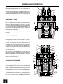
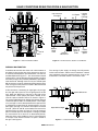
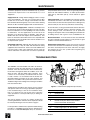
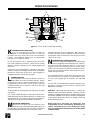
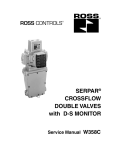
ROSS CONTROLS®
®
SERPAR
CROSSFLOW
DOUBLE VALVES
with L-G MONITOR
Size 4
Service Manual 368A
TABLE OF CONTENTS
Page
INTRODUCTION...........................................................................................
2
NORMAL VALVE OPERATION . ................................................................... 3
VALVE CONDITIONS RESULTING FROM A MALFUNCTION.................... 4-5
INSTALLATION NOTES................................................................................. 6
TEST PROCEDURE........................................................................................ 6
MAINTENANCE............................................................................................... 7
TROUBLESHOOTING.................................................................................. 7-8
REPAIR PROCEDURES............................................................................. 8-11
WARRANTY................................................................................................... 12
INTRODUCTION
The two main valve elements in the SERPAR® Crossflow
double valve with L-G monitor move simultaneously during
normal operation. If the valve elements do not move
simultaneously, the L-G monitor is designed to detect this
condition. The monitor reacts by exhausting pilot air and
blocking supply air to the pilot valves so that further valve
operation is inhibited. The valve is then said to be “locked
out” and cannot return to normal operation until the monitor
is reset.
A lockout is not necessarily an indication that the valve has
become faulty. Rather, it is an indication that the monitor
has detected non-simultaneous movement of the main valve
elements and that there is a condition in the system that
needs correction.
The SERPAR® Crossflow size 4 double valve with L-G monitor
consists of two main assemblies as shown in the illustration
below.
Pilot and Monitor Assembly – Two 3/2 normally closed
solenoid controlled pilot valves are mounted at the top of the
monitor housing. The pilots are connected to the electrical
power supply via dropcords and plug-in electrical connectors.
Each pilot valve controls one of the valve elements in the
valve body assembly (see below). The monitor contains a
pressure controlled spool, the movement of which can trigger
the monitor’s mechanical lockout mechanism.
Valve Body Assembly – The valve body has parallel flow
paths which incorporate two in-to-out crossflow paths, two 3/2
normally closed poppet valve elements, plus spool elements
to control the flow of air in the crossflow passages. Models
are available with the inlet port on either the left or the right
side* of the valve body. Inlet and outlet ports have threaded
flanges which bolt to the valve body, and a silencer is bolted
directly to the exhaust port.
*Illustrations in this manual show valve bodies with inlet ports
on the right.
ROSS CONTROLS®
NORMAL VALVE OPERATION
F
Becoming thoroughly familiar with the functions of the
SERPAR® Crossflow double valve and its L-G monitor
will help in analyzing lockouts and finding their causes.
The next few pages should be studied carefully to get an
understanding of both the normal valve functioning and
what happens when a malfunction occurs.
F
C
M
M
CONDITIONS AT START
Inlet air is blocked from the outlet port by two normally
closed valve elements A and B (see Figure 1). The outlet
port 2 is connected to the exhaust port 3. Pilot supply
air is carried via passage 4 around monitor spool C, and
up to the two normally closed pilot valves F. Spool C is
the sensing element of the L-G monitor and is kept in its
center position by springs M.
Refer also to the schematic diagram of pilot air flow given
in Figure 5.
4
A
B
1
SOLENOIDS ENERGIZED
Figure 1 — Solenoids Not Energized
Simultaneously energizing the two solenoids “a” and “b”
(see Figure 2) causes the two pilot poppets E to shift
upward. This closes the pilot exhaust passages 7 and
opens the pilot supply passages. Pilot air can then go from
the supply passage 4 to the main valve piston poppets J
via passages 9. Pressure on the piston poppets shifts
the main valve elements. This closes off the exhaust port
3 and connects inlet port 1 to outlet port 2 via crossflow
passages 10 and 11.
With the main valve inlet poppets U and V open, the
monitoring passages 6 are open to inlet pressure which
is directed to both ends of the monitor spool C. Because
these monitoring pressure signals are equal, spool C
remains in its center position.
SOLENOIDS DE-ENERGIZED
7
b
E
C
7
a
E
9
9
J
J
4
6
Simultaneously de-energizing solenoids “a” and “b” allows
the two pilot poppets E to return to their normally closed
positions (Figure 1). Pilot pressure on the main valve
pistons J is exhausted through the pilot exhaust passages
7. The main valve elements A and B return to their normal
deactuated positions. Inlet air is again blocked by poppets
U and V. Pressure at outlet port 2, at the ends of spool C,
and in the monitoring passages 6 is exhausted through
port 3. This completes the normal operating cycle, and
the valve has returned to the CONDITIONS AT START
described above.
6
1
11
V
10
U
Figure 2 — Solenoids Energized
www.rosscontrols.com
VALVE CONDITIONS RESULTING FROM A MALFUNCTION
Inlet Pressure
Passages
C
YB
YA
M
M
Lockout
Signal
Passage
L-G Spool
J
4
B
6
A
1
SB
10
Manual
Reset
Valve
Lockout
Mechanism
U
Figure 3 — Valve in Faulted Condition
Passage 4
From L-G
Reset
Spool to Interlock
Pilots
Spool
Figure 4 — Horizontal Cross Section of L-G Monitor
DURING A MALFUNCTION
If conditions do not allow one of the main valve elements to
be shifted, or do not allow one of the elements to return to
its normally closed position upon deactuation, we have the
condition depicted in Figure 3 — one valve element closed
and one open. Inlet air flowing past open poppet U and into
crossflow passage 10 is practically blocked by spool SB on
valve element B. Although some air can pass around spool
SB, the amount is so small, and the exhausting capacity of the
valve so large, that the pressure at outlet 2 does not exceed
two percent of inlet pressure.
At the same time, a monitoring air signal goes via passage
6 to the right end of spool C, but no signal goes to the left
end. When the difference in pressure at the ends of the
spool exceeds 1.5 bar (20 psi) the spool is shifted. In this
case the spool is shifted to the left as shown in Figure 5.
The spring-loaded lockout pin K drops into lockout groove 8
so that the spool is held in its shifted position. Pilot supply
air in passage 4 is then diverted around the spool and out
to atmosphere via bleed vent YA. Simultaneously, air in the
pilot supply passage 9 is vented to atmosphere via bleed
vent YB. (Vents YA and YB are located on the back of the
monitor housing as shown in Figure 9.) This exhausting of
pilot air removes pressure from piston J making it possible
for valve element A to return to its deactuated position.
Note that these same conditions occur if valve element B
is the open valve element and the L-G spool is shifted to
the right. See Figure 5.
The venting of pilot supply air through vent YA prevents
further valve actuation, and the valve is “locked out.” Normal
valve operation cannot be restored until the cause of the
malfunction is corrected and the L-G monitor is reset.
YA
8
9
YB
Spool Shifted Left
4
K
8
YA
9
YB
Spool Shifted Right
ROSS CONTROLS®
4
K
Figure 5 — Lockout Positions of L-G Spool
VALVE CONDITIONS RESULTING FROM A MALFUNCTION
Pilot
b
Pilot
a
Pilot
b
Reset
Interlock
Reset
L-G Spool
Centered
L-G Spool
Lockout Pin
Retracted
Manual
Reset
Valve
Pilot
a
Interlock
YB
YA
Lockout Pin
Engaged
Lockout
Mechanism
Pilot Supply
From Inlet Port
Manual
Reset
Valve
Lockout
Mechanism
Pilot Supply
From Inlet Port
Figure 6 — Normal Pilot Air Flow
Figure 7 — Pilot Air Flow During Lockout
Normal Operation. Pilot air supply from the inlet port of
the double valve flows around the L-G spool, past the reset
interlock spool, and on to the pilots. When the pilot solenoids
are energized, pilot air goes to the pistons of the main valve
elements.
During Lockout. The L-G spool is shifted off center. The springloaded lockout pin engages a slot in the spool to keep it in the
shifted position. Pilot supply air is then diverted to atmosphere
via vent YA. Air remaining in the pilot lines is exhausted to
atmosphere via vent YB.
RESETTING THE L-G MONITOR
After the cause of a lockout has been corrected, the spool in the
L-G monitor must be reset to its normal center position in order
for the valve to function properly. To ensure that the equipment
controlled by the valve does not begin operating immediately
after resetting the monitor, electrical power to the valve solenoids
must be off before resetting. Otherwise, the energized solenoids
will actuate the valve as soon as the reset pressure signal is
removed.
The resetting action is accomplished by applying air pressure of
at least 2 bar (30 psig) to the lockout mechanism. This is done
in one of two ways, depending on the particular valve model.
Manual reset models have a reset valve which directs inlet air
to the reset mechanism. Remote reset models use an external
pressure source and an external reset valve to apply the pressure
via a threaded reset port in the monitor body.
Regardless of the type of reset, applying the reset pressure
produces two results: (1) lockout pin K (see Figure 5) is lifted
out of the lockout groove so that the centering springs M can
return the spool to its center position; and (2) the reset interlock
spool (see Figures 4 and 8) is shifted so that the pilot air supply
passage is blocked and remains blocked during the resetting
process. In this way the valve is kept inoperative while resetting
air pressure is applied and any attempt to circumvent the function
of the L-G monitor is hindered. However, to ensure that the
equipment controlled by the valve does not begin operating
immediately after resetting the monitor, electrical power to the
valve solenoids must be off. Otherwise, the energized solenoids
would actuate the valve as soon as the reset pressure signal
is removed.
Pilot
b
Pilot
a
Reset
Interlock
L-G Spool
Centered
Lockout Pin
Retracted
Manual
Reset
Valve
Lockout
Mechanism
Pilot Supply
From Inlet Port
Figure 8 — Pilot Air Flow During Reset
During Reset. When the manual reset valve is actuated pilot
supply air goes to the lockout mechanism so the lockout pin is
retracted. The L-G spool then recenters itself. At the same time,
air flow to the reset interlock moves the interlock spool so that
air to the pilots is cut off and remains so as long as the reset
valve is actuated.
On remote reset models the manual reset valve is replaced by
a threaded reset port, and air flow to the reset interlock moves
the spool so that air to the pilots is cut off and remains so as
long as remote reset air is applied.
www.rosscontrols.com
INSTALLATION
Pneumatic equipment should be installed only by persons
trained and experienced in the installation of such equipment.
Air Lines. Before installing a double valve in an existing
system, the air lines must be blown clean of all contaminants.
One of the leading causes of lockouts is foreign material from
the air lines which becomes lodged in the valve. It is strongly
recommended that an air filter be installed ahead of and close
to the valve and that the filter be properly maintained.
Valve Inlet 1. (See Figure 9.) DO NOT RESTRICT THE AIR
SUPPLY. Any restriction of the supply lines (sharp bends,
undersize lines, etc.) reduces the speed at which the outlet
volume is pressurized. See Inadequate Air Supply on page 8.
Valve Outlet 2. For faster pressurizing and exhausting of
the outlet volume, locate the valve as close as possible to the
mechanism being operated. Also, any restriction in the outlet
lines will reduce both pressurizing and exhausting speeds.
Valve Exhaust 3. DO NOT RESTRICT EXHAUST. Limiting
the exhausting speed decreases an important safety feature
of the double valve. During a malfunction in which only one
of the valve elements is shifted, air escaping past the spool in
the valve stem of the closed valve element (see Figure 3) must
be quickly exhausted to keep outlet pressure at or below the
design pressure of two percent of inlet pressure. See Undersize
or Plugged Silencer, page 11.
Remote Reset Port N. Remote reset models require a minimum
supply pressure of 2 bar (30 psig). Use a 3/2 reset valve.
Lockout Signal Port S. Can be connected to a normally closed
pressure switch to operate a lockout indicator light. Loss of
pressure signifies a lockout.
Electrical Connections. The solenoid lugs can be faced
forward, to the sides, or to the rear by loosening the knurled
nuts on the tops of the solenoids and rotating the lugs to the
desired position. The electrical supply must be of the correct
voltage and frequency. The solenoids are rated for continuous
duty at 85% to 110% of the voltage marked on the solenoid.
A supply voltage that does not fall within this range can
cause nuisance lockouts or premature solenoid burnouts. If
electrical power is supplied through a transformer, it should
be capable of handling the inrush current of the solenoids
without significant voltage drop.
Mounting Position. It is recommended that valves be mounted
with the solenoids on top wherever possible.
Pressure Range. Inlet pressure should fall in the range of 2 to 7
bar (30 to 100 psig). Pressure below this range may render the
L-G monitor inoperative or lead to intermittent lockouts. Pressure
above this range can nullify the monitor lockout function, and
also causes excessive poppet impact which shortens the life
of the valve.
Temperature Range. Ambient temperature should be in the
range of 4°C to 50°C (40°F to 120°F). Temperature of the
operating media should be in the range of 4°C to 80°C (40°F
to 175°F). Improper valve action and/or shortening of valve life
can result if these temperature limits are not observed.
TEST PROCEDURE
Valves are tested after assembly to assure proper operation,
but it is recommended that the following tests be made when
the valve is initially installed, or whenever the valve has been
disassembled . These tests should be made both at the repair
bench and at the installation. At the installation, take normal
press operation safety precautions during these tests to avoid
the potential for human injury or damage to equipment.
are two bleed vents, YA and YB (see Figure 9). Bleed vent YA
should emit a continuous flow of air. De-energize the other
solenoid (“b”).
All tests should be performed only by persons trained and
experienced in the testing of pneumatic equipment.
6. Reset the monitor by pressing the reset button, or if the valve
is a remote reset model apply pressure of at least 2 bar (30 psig)
to reset port N. Air flow from bleed vent YA should stop. Remove
reset pressure.
If the valve fails any of the following tests, refer to Troubleshooting
beginning on page 7.
1. Remove silencer.
2. Apply compressed air in the 2 to 7 bar (30 to 100 psig) range
to inlet port 1. There should be no pressure at outlet port 2 or
exhaust port 3.
3. Connect outlet port 2 to a small volume fitted with a damped
pressure gauge. Simultaneously energize both solenoids. Inlet
and outlet pressures should be equal and there should be no
leakage at the exhaust port.
4. De-energize solenoid “a” (one nearest the inlet port). Outlet
pressure should drop to approximately two percent of inlet
pressure and there should be only a brief flow of exhaust air
which stops as the monitor locks out. On the back of the monitor
5. Step 4 should have caused the monitor to lock out. Energize
both solenoids simultaneously. There should be no pressure at
either the outlet or exhaust port. Bleed vent YA should continue
to emit air. De-energize both solenoids.
7. Simultaneously energize both solenoids. Inlet and outlet
pressure should be equal and there should be no leakage at
the exhaust port.
8. De-energize solenoid “b.” Conditions should correspond to
those described in step 4 above. De-energize solenoid “a.”
9. Step 8 should have caused the monitor to lock out. Energize
both solenoids simultaneously. Conditions should correspond to
those described in step 5 above. De-energize both solenoids.
10. Reset the monitor as described in step 6. Bleed air should
stop.
11. Install silencer. Repeat steps 2 through 10 with silencer
installed. The valve is now ready for normal operation.
ROSS CONTROLS®
MAINTENANCE
compounded for air line service. These are generally petroleum
based oils with oxidation inhibitors, an aniline point between
180°F (82°C) and 220°F (104°C), and an ISO 32 or lighter
viscosity.
Pneumatic equipment should be maintained only by persons
trained and experienced in the maintenance of such
equipment.
Supply Clean Air. Foreign material lodging in valves is a major
cause of breakdowns. The use of a 5-micron-rated air filter
located close to the valve is strongly recommended. The filter
bowl should be drained regularly. If its location makes draining
difficult, the filter should be equipped with an automatic drain.
Cleaning the Valve. If the air supplied to the valve has not been
well filtered, the interior of the valve may accumulate dirt and
varnish which can affect the valve’s performance. Although very
tolerant of dirty air, the valve may sometimes need cleaning.
Check Lubricator Supply Rate. A lubricator should put a fine
oil mist into the air line in direct proportion to the rate of air flow.
Excessive lubrication can cause puddling in the valve and lead
to malfunctions. For most applications an oil flow rate in the
lubricator of one drop per minute is adequate. (Note that the
double valve does not itself require air line lubrication.) See
below for information about lubricants that are compatible with
the materials used in the double valve and are suitable for use
in compressed air systems.
To clean the valve, use any good commercial solvent or kerosene.
Do not use a chlorinated solvent or abrasive materials. The
former damages seals, and abrasives can do permanent
damage to metal parts. Before reassembling the valve lubricate
all sliding surfaces with a grease such as MobilGrease 28.
Compatible Lubricants. Although this valve does not require
air line lubrication, it may be used with lubricated air being
supplied to other mechanisms. Some oils contain additives that
can harm seals or other valve components and so cause the
valve to malfunction. The best oils to use are those specifically
Replace Worn Components. In most cases it is not necessary
to remove the valve from its installation for servicing. However,
turn off the electrical power to the valve, shut off the air supply,
and exhaust the air in the system before beginning any
disassembly operation.
Electrical Contacts. In the electrical circuits associated with
the valve solenoids, keep all switches or relay contacts in good
condition to avoid solenoid malfunctions.
TROUBLESHOOTING
The SERPAR® Crossflow double valve with L-G monitor is
designed to monitor the outlet pressures of the main valve
elements. If the valve elements fail to move simultaneously
the monitor is designed to detect this condition, act to shut
down the valve, and thus inhibit further operation. Such
a lockout is not necessarily an indication that the valve
is faulty. Rather, it is an indication that the monitor has
detected improper movement of the valve elements, and
that there is a condition in the system that needs correction.
Troubleshooting involves finding and correcting the condition
that caused the lockout.
Troubleshooting should be done only by persons trained
and experienced in the servicing of pneumatic equipment.
If the troubleshooting is done at the installation rather
than at a repair bench, take normal press operation
safety precautions to avoid possible injury or damage to
equipment.
The chart on page 8 can serve as a guide to locating and
correcting malfunctions. After the valve is repaired, it should
be tested by following the Test Procedure on page 6.
If valve operation is still abnormal, repeat the troubleshooting
procedure or call ROSS Technical Services department in
the U.S.A. at 1-888-GET-ROSS(835-7677) for assistance.
N
S1
S
YB
YA
1
Figure 9 — External Ports (Right-inlet-port models)
1
Inlet port (1)*
2
Outlet port (2)*
3
Exhaust silencer
YA, YB
L-G monitor bleed vents
N
Remote reset port. Manual reset models have a reset button located here.
S1
Lockout signal port; 10-32 (M5) threads
S2
Lockout signal port; 1/8" NPT threads
*Ports 1 and 2 reversed on left-inlet-port models.
www.rosscontrols.com
TROUBLESHOOTING CHART
If the valve fails to operate properly, apply the Tests given below. Check for Symptoms. Possible Causes and Repair Procedures
are given for each symptom. The repair procedures are detailed on the following pages. After the valve is repaired, follow the Test
Procedure given on page 6 before returning the valve to service.
Tests
Symptoms
Possible Causes
TEST 1 — Electrical power to No lockout bleed and no
solenoids must be off. Remove exhaust air
silencer. Check for lockout
bleed air at vent YA. Check for exhaust air.
Have both lockout bleed
air and exhaust air
Have lockout bleed air
but no exhaust air
TEST 2 — With electrical power
Will not reset
remaining off and silencer removed, attempt to reset the monitor. (See page 5.)
Resets properly
TEST 3 — Take normal press
Locks out intermittently
operation safety precautions
during this test. With silencer
removed and monitor reset,
cycle valve several times by energizing solenoids in the
Valve performs normally
normal manner.
Locks out on first cycle
TEST 4 — With silencer removed
Locks out as solenoids
and monitor reset, proceed as are energized
follows: Taking normal press
operation safety precautions, energize solenoids, hold energized, then de-energize solenoids. Be
sure both solenoids are energized
Locks out as solenoids
and de-energized simultaneously.
are de-energized
Repair
Procedures
Inadequate air supply
Inadequate voltage at solenoids
Both solenoids inoperative
Faulty seals on monitor spool
Contaminants in monitor
Faulty seals on monitor spool
Main inlet poppets not sealing
Jammed solenoid plunger
Proceed to TEST 2
A
B
C
E
G
E
J
C
—
Faulty seals on monitor spool
Bent lockout pin
Contaminants in monitor
Proceed to TEST 3.
Inadequate air supply
Incorrect voltage at solenoids
Worn bore in monitor
Varnish deposits in valve
Excessive lubrication
Transient foreign material
Dirty or undersize silencer
Proceed to TEST 4.
Inadequate air supply
Jammed solenoid plunger
Pilot inlet poppet not sealing
Varnish deposits in valve
Excessive lubrication
Leaking piston poppet seal
Varnish deposits in valve
Excessive lubrication
E
H
G
—
A
B
F
L
M
I, J
N
—
A
C
D
L
M
K
L
M
REPAIR PROCEDURES
A
INADEQUATE AIR SUPPLY
Even though the air supply pressure may be in the
correct range, the volume of air supplied can be too
small. An inadequate air supply volume causes an excessive
pressure drop during valve actuation. Thus, even though the
pilot air supply is sufficient to unseat the main valve elements
the pressure drop which results from filling the outlet volume
depletes the pilot air supply. The main valve elements may
then be only partially actuated so the inlet air flows out both
the outlet and exhaust ports.
The lowered pilot pressure can also exaggerate the effects of
small differences in the operating characteristics of the pilots
and valve elements so that the valve elements may not move
simultaneously. This can produce intermittent lockouts.
Check for very long, undersize, or pinched supply lines, sharp
bends, and restrictive fittings. All can reduce the air volume
supplied to the valve.
ROSS CONTROLS®
REPAIR PROCEDURES
Jammed solenoid plunger. This problem is usually the result
of physical abuse (hitting the solenoid, for example). With this
kind of damage the entire solenoid and pilot assembly should
be replaced (part no. 806A79). Do not attempt to repair the
plunger or its sleeve.
D
FAULTY PILOT SEALS
To inspect pilots remove the electrical receptacle
connectors. Shut off, exhaust, and lock out the air supply
to the valve.
Remove the knurled nuts and washers at the tops of the
solenoids. Lift off solenoids. Remove screws in pilot retaining
plates and lift out the pilot assemblies. Take care that the
moveable plungers do not fall out and become damaged.
Figure 10 —
Cross Section of Solenoid Pilot Assembly (806A79)
B
INCORRECT VOLTAGE AT SOLENOIDS
Solenoids are rated for continuous duty at 85% to 110%
of the voltage shown on the side of the solenoid. A supply
voltage that does not fall within this range can cause nuisance
lockouts, premature solenoid burnout, or impact damage.
The supply voltage should be checked with a voltmeter at a point
in the supply line as close as possible to the valve, preferably
at the solenoid coil terminals. Read the voltmeter while the
solenoids are energized. If the voltage falls below the allowable
operating range, the electrical supply is inadequate even though
the supply voltage may be correct without the electrical load of
the solenoids (when the solenoid coil is disconnected from the
circuit).
A voltage that exceeds the allowable maximum can cause
premature solenoid burnout or excessive wear on the exhaust
poppet face at the upper end of the solenoid plunger. If an
incorrect voltage is being supplied, this condition must be
corrected before any attempt is made to put the valve back in
service.
C
FAULTY SOLENOID
Solenoids for size 4 double valves are of rugged
construction and give relatively trouble-free performance.
However, long use or abuse can lead to malfunctions.
Defective solenoid coil. The coil can be checked with an
ohmmeter. Remove the electrical receptacle connector and
attach the ohmmeter to the two curved prongs; the flat prong
is the ground prong. If the reading is zero or infinite, the coil is
defective and must be replaced (part no. 290B33). The most
common cause of solenoid burnout is incorrect supply voltage.
See Repair Procedure B. If the voltage is wrong, it must be
corrected before the valve is put back into service.
Inspect poppets on both ends of the plungers, and the poppet
seats in plunger housing and monitor body. Significant wear
or damage to a poppet or exhaust poppet seat requires
replacement of the entire pilot assembly (part no. 806A79).
Damage to the poppet seat in the monitor body requires
replacement of the entire monitor. No attempt should be made
to reface a poppet seat because this will change the stroke
of the plunger and can affect the operating characteristics of
the pilot. If the pilot seals are swollen or have deteriorated,
improper lubricants (see page 7) may be the cause.
Check the motion of the plunger within its housing. It should
move freely throughout its stroke. Any tendency to bind suggests
damage to the housing, and the pilot assembly should be
replaced (part no. 806A79). Reassemble the pilots in the reverse
order of their disassembly.
E
DAMAGED SEALS ON MONITOR SPOOL
Damaged seals on spool C (Figure 11) can result in air
leaks or cause the spool to jam so that the L-G monitor
does not function properly.
Before disassembly to inspect the monitor, remove the electrical
receptacle connectors from the solenoids. Shut off, exhaust, and
lock out the air supply to the valve. Proceed as follows:
1.
Remove the four socket-head screws which join the monitor
to the valve body. Remove the monitor.
2.
Remove pin X (Figure 11), retaining ring Y, and lockout
pin assembly Z.
3.
Remove pins T, retaining rings R, end plugs G, and
springs M.
4.
Push out spool C. If the spool seems to be stuck, make sure
that the lockout pin assembly has been removed before
proceeding. Handle with care while inspecting the Teflon
surfaces of the four slipper seals for scratches or other
defects that could affect their sealing qualities.
If any of the seals are damaged, replace the entire spool-andseal assembly (part no. 545K77). However, be sure to inspect
the monitor bore for burrs or grit that might be the cause of the
damage to the seals. See Repair Procedure F for remarks
about bore wear. Assembly is the reverse of disassembly.
Before assembling, inspect for a bent lockout pin. See Repair
Procedure H.
www.rosscontrols.com
REPAIR PROCEDURES
C
M
M
G
G
T
T
R
R
Repair Kit for Manual
Reset Valve is 544K77.
K
Y
Z
X
Figure 11 — Cross Section of L-G Monitor
F
WORN SPOOL BORE
A worn spool bore can cause lockouts because of poor
sealing and consequent air leakage. To check bore,
disassemble as described in Repair Procedure E. If the bore
is worn or badly scratched, the entire monitor must be replaced
(part no. 804C79A for manual reset monitor; 805C79 for remote
reset monitor).
G
J
MAIN INLET POPPET NOT SEALING
If an inlet poppet is not sealing, air can be detected
escaping at the exhaust port. Foreign particles are
sometimes responsible for holding a poppet off its seat. If the
monitor cannot be reset so that an attempt can be made to flush
out foreign particles by cycling the valve, it will be necessary to
disassemble the valve and clean it.
CONTAMINANTS IN SPOOL BORE
A buildup of grease, oil, water, or other contaminants
in the spool bore can restrict or prevent movement of
the spool. This can create an unsafe condition by preventing
the L-G monitor from locking out when it should, or can prevent
resetting after a lockout has occurred. To inspect and clean the
bore, follow disassembly steps in Repair Procedure E.
Before disassembly, remove the electrical receptacle connectors
at the solenoids. Shut off, exhaust, and lock out the air supply
to the valve. Remove the four socket-head screws that join
the monitor and the valve body. Lift off the monitor and pilot
assembly. Proceed with valve body disassembly as follows
(see Figure 12):
H
1.
Remove cotter or knurled pins P through the front of the
valve body. Some valve models have plain pins which must
be removed through the back of the valve body.
2.
Remove retaining rings H, end plugs W, and springs BA.
3.
Pull inlet poppets U and V off the valve stems.
4.
Lift the remaining parts of the valve elements out the top of
the valve body.
BENT LOCKOUT PIN
If lockout pin K (Figure 11) is bent, it will not retract
when resetting pressure is applied and the valve
remains locked out. See the disassembly instructions in Repair
Procedure E to remove the lockout pin. Assembly with a new
pin (lockout pin kit is 542K77) is the reverse of disassembly.
I
TRANSIENT FOREIGN MATERIAL
If the valve resumes normal operation after being reset,
the cause of the lockout may have been a transient foreign
particle. A bit of scale or other foreign material could lodge at
various points in the valve to cause a nuisance lockout. After
resetting, the air flow of the next operating cycle can “wash”
the foreign material out, thus permitting the valve to return to
normal operation. This situation is most common after a period
of press inactivity. An efficient, properly maintained filter located
close to the valve will help to eliminate this problem.
10 If the inlet poppets U and V are damaged or have deteriorated,
replace them. (Valve body kit is 541K77.) Deteriorated
poppet material suggests the use of improper lubricants. For
information about compatible lubricants see page 7.
While the valve is disassembled, also inspect the piston poppets
J for damage, and the bores for varnish deposits. See Repair
Procedures L and M.
ROSS CONTROLS®
REPAIR PROCEDURES
J
BB
BB
V
BA
U
BA
W
H
P
P
W
H
Figure 12 — Cross Section of Valve Body Assembly
K
LEAKING PISTON POPPET SEAL
A worn or damaged piston poppet seal BB (see
Figure 12) can allow pilot pressure to leak past
the piston and cause erratic valve action and intermittent
lockouts. Disassemble to inspect seals. For disassembly
instructions, see Repair Procedure J.
For the U-cup piston seals to perform properly they must
have some compression in the bore. Also inspect for varnish
deposits, and wear or damage to piston and inlet poppets and
their seats.
Replace any worn or damaged parts. (Valve body service kit is
541K77.) If any parts show signs of deterioration, incompatible
lubricants or solvents may be the cause. See paragraphs on
compatible lubricants and cleaning on page 7.
L
VARNISH DEPOSITS
Varnish deposits in the valve may affect the motion of a
piston poppet and cause intermittent lockouts. Varnish
results from the action of oxygen on lubricating oils, and can
be aggravated by excess heat. Varnish can also come from
overheated compressor oil carried over into the air lines and
deposited in the valve.
To disassemble for cleaning follow the steps given in Repair
Procedure J.
Use a water soluble detergent for cleaning varnished areas.
Avoid chlorinated solvents (trichloroethylene, for example) and
abrasive materials. The former can damage seals and poppets,
and abrasives can do permanent damage to metal parts.
M
EXCESSIVE LUBRICATION
Excess oil on the piston wall can sometimes cause
erratic valve action and result in intermittent lockouts. Air
line lubrication is not required for this valve, but if a lubricator is
used it should deposit only a film of oil on the piston walls.
Check the lubricator in the air supply line. Only enough oil
should be injected to produce a slight discoloration on a piece
of white paper when it is held close to the exhaust port of the
valve for a few cycles.
N
UNDERSIZE OR PLUGGED SILENCER
The silencer supplied with SERPAR® Crossflow double
valves is designed for minimal back pressure. However,
after long usage with contaminant laden air it may become
clogged. The increased back pressure can cause erratic
motion of the valve elements and lead to intermittent lockouts.
A dirty silencer should be removed and cleaned with a water
soluble detergent solution.
If a non-standard silencer is used, excess back pressure may
result if the silencer is too restrictive. Be sure the silencer used
is of the correct capacity (part no. 318C86). See CAUTION
below.
If a valve locks out intermittently but performs normally when
the silencer is removed, clean the silencer or replace it with
ROSS silencer 318C86.
CAUTION: Restricting the exhaust ports of valves can
adversely affect their proper operation. Silencers must be
resistant to clogging and have flow capacities which match
the exhaust capacities of the valves. Possible contamination
of the silencer matrix may result in a change in flow and
increased back pressure.
ROSS expressly disclaims all warranties and
responsibility for any unsatisfactory performance or
injuries caused by the use of the wrong type, wrong
size, or inadequately maintained silencer installed with
a ROSS product.
www.rosscontrols.com
11
GLOBAL Reach with a LOCAL Touchsm
ROSS EUROPA® GmbH
ROSS CONTROLS®
Langen, Germany
Telephone: + 49-6103-7597-0
Fax: + 49-6103-74694
Email: [email protected]
www.rosseuropa.com
Troy, MI., U.S.A.
Telephone: + 1-248-764-1800
Fax: + 1-248-764-1850
In the United States:
Safety Department: 1-248-764-1816
Customer Service: 1-800-GET ROSS
(438-7677)
Technical Service: 1-888-TEK-ROSS
(835-7677)
www.rosscontrols.com
ROSS ASIA® K.K.
Kanagawa, Japan
Telephone: + 81-427-78-7251
Fax: + 81-427-78-7256
www.rossasia.co.jp
ROSS UK Ltd.
Birmingham, United Kingdom
Telephone: + 44-121-559-4900
Fax: + 44-121-559-5309
Email: [email protected]
ROSS CONTROLS (CHINA) Ltd
ROSS SOUTH AMERICA Ltda.
São Paulo, Brazil CEP 09725-020
Telephone: + 55-11-4335-2200
Fax: + 55-11-4335-3888
Email: [email protected]
Your local ROSS distributor is:
Shanghai, China
Telephone: + 86-21-6915-7951
Fax: + 86-21-6915-7960
Email: [email protected]
ROSS CONTROLS® INDIA Pvt. Ltd.
Chennai, India
Telephone: + 91-44-2624-9040
Fax: + 91-44-2625-8730
Email: [email protected]
DIMAFLUID s.a.s.
Saint Ouen, France
Telephone: + 33-01-49-45-65-65
Fax: + 33-01-49-45-65-30
Email: [email protected]
www.dimafluid.com
Warranty
Products manufactured by ROSS are warranted to be free of defects in material and workmanship for a period of one year
from the date of purchase. ROSS’ obligation under this warranty is limited to repair or replacement of the product or refund of
the purchase price paid solely at the discretion of ROSS and provided such product is returned to ROSS freight prepaid and
upon examination by ROSS such product is found to be defective. This warranty shall be void in the event that product has
been subject to misuse, misapplication, improper maintenance, modification or tampering. THE WARRANTY EXPRESSED
ABOVE IS IN LIEU OF AND EXCLUSIVE OF ALL OTHER WARRANTIES AND ROSS EXPRESSLY DISCLAIMS ALL
OTHER WARRANTIES EITHER EXPRESSED OR IMPLIED WITH RESPECT TO MERCHANTABILITY OR FITNESS
FOR A PARTICULAR PURPOSE. ROSS MAKES NO WARRANTY WITH RESPECT TO ITS PRODUCTS MEETING THE
PROVISIONS OF ANY GOVERNMENTAL OCCUPATIONAL SAFETY AND/OR HEALTH LAWS OR REGULATIONS. IN NO
EVENT SHALL ROSS BE LIABLE TO PURCHASER, USER, THEIR EMPLOYEES OR OTHERS FOR INCIDENTAL OR
CONSEQUENTIAL DAMAGES WHICH MAY RESULT FROM A BREACH OF THE WARRANTY DESCRIBED ABOVE OR
THE USE OR MISUSE OF THE PRODUCTS. NO STATEMENT OF ANY REPRESENTATIVE OR EMPLOYEE OF ROSS
SHALL EXTEND THE LIABILITY OF ROSS AS SET FORTH HEREIN.
Printed in the U.S.A. - Rev. 05/07
© 2007 ROSS CONTROLS®. All Rights Reserved.
Form A10068