1
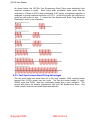
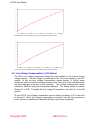
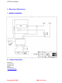
Rev.0 03/18/10
HPC-B SERIES USER MANUAL
HIGH POWER CONTROL MODULE
BURST FIRING VERSION
COPYRIGHT 2009
HBCONTROLS
HPC-B User Manual
TABLE OF CONTENTS
1. Ordering Codes................................................................................................................... 2 2. Description .......................................................................................................................... 2 3. Installation ........................................................................................................................... 3 3.1 Mounting Instructions................................................................................................... 3 3.2 Electrical Connections ................................................................................................. 3 4. Operation ............................................................................................................................ 3 4.1 Power Supply............................................................................................................... 3 4.2 24V Power Fusing........................................................................................................ 3 4.3 Command Input ........................................................................................................... 3 4.3.1 Input Fail-safe Protection ...................................................................................... 4 4.4 Cycle Times ................................................................................................................. 4 4.5 Cycle Times – 266mS Selection (Fast Synchronous Burst Firing)............................... 4 4.5.1 Fast Synchronous Burst Firing Mode.................................................................... 4 4.5.2 Fast Synchronous Burst Firing Advantages.......................................................... 5 4.6 Line Voltage Compensation (-LVC Option) .................................................................. 6 4.6.1 Line Voltage Compensation Nominal Adjustment................................................. 7 4.7 Power Limit .................................................................................................................. 7 4.7.1 Power Limit Adjustment Procedure....................................................................... 7 4.8 Configuration Dipswitch ............................................................................................... 7 4.9 Output LED .................................................................................................................. 8 4.10 Three Phase Operation................................................................................................ 8 4.11 Wiring Multiple Units in Single Phase or Three Phase Applications............................. 8 4.11.1 Connecting Power & Commands In Parallel ......................................................... 8 5. Electrical Specifications ...................................................................................................... 8 6. Mechanical Dimensions .................................................................................................... 10 7. WIRING DIAGRAM - SINGLE PHASE.............................................................................. 10 8. WIRING DIAGRAM 3 PHASE 4 WIRE Y CONNECTION ... Error! Bookmark not defined. 9. WIRING DIAGRAM 3 PHASE INSIDE DELTA CONNECTIONError! Bookmark not defined. 10. Contact Information ....................................................................................................... 10 1. Ordering Codes
Part#
HPC-P
HPC-B
HPC-B-LVC
Description
Phase Angle Control Module SCR GATE DRIVE (see HPC-1P User Manual)
Burst Firing Control Module SCR GATE DRIVE
Burst Firing Control Module SCR GATE DRIVE w/Line Voltage Compensation
2. Description
The HPC is a phase angle / burst fire control module designed for use with high power
back to back SCR modules. The power delivered to the load is proportional to the
command input signal.
Features:
• Zero Cross Firing for low EMI
• Fast Synchronous Burst Algorithm provides true linear power at fast cycle times
• Command input accepts 4-20mA, 0-10V, 0-5V, Pot, PWM
• Automatic frequency operation (45 to 65Hz)
• Adjustable Power % Limit
• Drives SCR gates directly
• Single phase and three phase control
Copyright 2009
HBCONTROLS
HPC-B User Manual
3. Installation
WARNING: FIRE HAZARD!! Even quality electronic components
CAN FAIL KEEPING FULL POWER ON! Provide a SEPARATE (redundant) OVER
TEMPERATURE SHUTDOWN DEVICE to switch the power off if safe temperatures are
exceeded.
WARNING: HIGH VOLTAGE!! This control module has high voltage on it.
This control must be installed in a GROUNDED enclosure by a qualified electrician in
accordance with applicable local and national codes including NEC and other applicable
codes. Provide a safety interlock on the door to remove power before gaining access to
the device.
3.1 Mounting Instructions
The HPC mounts in a 3.0” snap track and can be installed on a dinrail.
3.2 Electrical Connections
See the WIRING DIAGRAMS at the end of this document. Make sure the module ordered
is the correct module for the application before wiring. Before wiring the module all Dip
Switch settings for the command input and special features should be setup properly per
the Dipswitch Configuration Section.
4. Operation
4.1 Power Supply
The HPC power supply requirement is 24V AC +/-10% 47-63Hz OR 24VDC+15/-5%. The
line synchronization for phase angle and certain modes of burst firing has an input voltage
range of 100 to 600VAC, 30 to 90Hz.
4.2 24V Power Fusing
Fusing may be accomplished by fusing each module separately or fusing groups of the
modules with either primary or secondary fusing. The current draw of each HPC is
100mA max.
4.3 Command Input
The HPC can accept 4-20mA, 0-10V, 0-5V, and Potentiometer and PWM inputs. All
analog command inputs are not isolated from the 24V power Input. The type of command
input can be configured via the dipswitch. The default setting is 0-5V/potentiometer.
The PWM digital command input (PLC Interface) is optically isolated from the power
supply.
When wiring multiple HPC’s together, follow the guidelines in the Wiring Multiple HPCs
section.
Copyright 2009
HBCONTROLS
HPC-B User Manual
Any leg of the command input can tolerate shorts to the (0V) input. Connecting the 24V
power to the command input may cause damage to the unit.
4.3.1 Input Fail-safe Protection
If the signal sent to the HPC’s command input should become electrically open the control
output will be forced to an off state.
4.4 Cycle Times
The cycle time refers to the total time between an on and off cycle.
The HPC -B has 4 available cycle times settable via the dipswitches.
The cycle times are specified below in # of cycles and can be correlated to their
respective times using the table below for both 50 and 60 Hz Line frequencies:
Dip
Switch 1
Dip
Switch 2
#of
cycles
*OFF
ON
OFF
ON
*OFF
OFF
ON
ON
~16
60
600
6000
Cycle
Time
(60Hz)
266mS
1S
10S
100S
Cycle
Time
(50Hz)
320mS
1.2S
12S
120S
Resolution
( % of FS)
~1%
1.66%
0.166%
0.0166%
*Synchronous Firing Method
When burst firing AC with conventional PWM, there is a tradeoff between resolution and
cycle time. Generally the cycle time should be chosen based on the mass of the load to
be controlled; the larger the load mass, the longer the cycle time can be. For the best
possible resolution, its standard practice to choose the longest cycle time that can be
used without causing process ripple. Longer cycle times generally provide greater control
resolution, but the Fast Synchronous Burst setting provides excellent resolution at a fast
cycle time.
4.5 Cycle Times – 266mS Selection (Fast Synchronous Burst Firing)
When the HPC-B cycle time is set to 266mS (320mS @ 50Hz) the Fast Synchronous
Burst Firing mode is turned on. The cycle time becomes longer near zero and full power
levels to provide improved control resolution. For Example, since the HPC -1B generally
modulates 16 AC cycles, the lower limit in power that will maintain the cycle time is 1/16
or 6.25%. The HPC-B will use increased off periods below 6.25% power and above
94.75% power.
4.5.1 Fast Synchronous Burst Firing Mode
Copyright 2009
HBCONTROLS
HPC-B User Manual
As shown below, the HPC-B’s Fast Synchronous Burst Firing mode selectively fires
fractional numbers of cycles. Since pulse width modulation alone would limit the
resolution to 16 steps or 6.25% when modulating 16 AC cycles, a proprietary algorithm is
employed to provide improved resolution of 0.5-1%. In this firing mode, the cycle time is
varied as well as the on time. To select the Fast Synchronous Burst Firing Mode set
Diswitches 1 and 2 to the off position.
4.5.2 Fast Synchronous Burst Firing Advantages
The two plots below are actual data for a 425 degF capable 10KW resistive heater
ramped from 0-100% power over two hours. The first plot shows straight 16 cycle,
266mS cycle time PWM. Note the nonlinearity humps due to poor resolution. The
second plot shows the linearity improvement with the Fast Synchronous Burst. Any
visible overall curvature is a normal heater characteristic.
Copyright 2009
HBCONTROLS
HPC-B User Manual
450
400
350
300
250
200
150
100
50
17:30:00
17:55:00
18:20:00
18:45:00
19:10:00
h:min:s
Fast PWM of zero cross fired loads can result in poor linearity / resolution (above)
450
400
350
300
250
200
150
100
50
15:00:00
15:25:00
15:50:00
16:15:00
16:40:00
h:min:s
Fast Synchronous Burst algorithm results in excellent linearity / resolution (above)
4.6 Line Voltage Compensation (-LVC Option)
The HPC‘s line voltage compensation keeps the power constant on the load as the line
voltage changes. The line voltage is measured via the 24V power applied to the HPC
module. To use the Line Voltage Compensation feature properly, a 24VAC power
transformer should be fed from the same mains as the load circuit to be controlled as per
the wiring diagrams at the end of this document. Line Voltage Compensation can be
enabled or disabled using the configuration dipswitch. The default setting is enabled
(Switch # 1 is OFF). To disable the Line Voltage Compensation, set switch # 1 to the ON
position.
On the HPC-B, Line Voltage compensation can be ordered by adding –LVC to the suffix
of the part #. When line voltage compensation is specified, only the fast synchronous
burst cycle time is available (the dipswitch setting of cycle times is disabled).
Copyright 2009
HBCONTROLS
HPC-B User Manual
With a 10% drop in lin e voltage, load power drops less th an 2%
(120V, 1KW, 14.4 O h m Load )
With ou t Lin e Voltage Compen sation
With HPC Lin e Voltage Compen sation
120VAC
120VAC
108VAC
(-10%)
108VAC
(-10%)
MAINS VOLTAGE
MAINS VOLTAGE
1KW
1KW
P= E
R
LOAD POWER
LOAD POWER
0.81KW
(~-20%)
4.6.1 Line Voltage Compensation Nominal Adjustment
The nominal adjustment pot sets the nominal level of output for the current line voltage
being measured via the 24VAC input.
4.7 Power Limit
The Power Limit feature is used in conjunction with the Line Voltage Compensation
feature to limit the actual voltage delivered to the load. The Power Limit is adjustable via
a potentiometer located just below the input terminal block. For this feature to work
properly Line Voltage Compensation must be turned on and the power transformer for the
HPC must be connected to the same mains as the load power is connected to. This
feature can be used without Line Voltage Compensation and will simply clip the command
signal to a set level.
4.7.1 Power Limit Adjustment Procedure
The Power Limit is adjustable from 5% to 100% of the max power. Setting the Power
Limit potentiometer half way corresponds to a Power limit of approximately 55%. With the
command input set to approximately 100% (on startup) turn the pot fully CCW. Then just
turn the pot CW until the desired maximum output Power is achieved. For this feature to
work as a true max limit, it is important that the Line Voltage Compensation be enabled
(this is the OFF position of Switch # 1).
If the line voltage compensation is set to OFF or not present in the ordering code, the max
limit will act as a percentage of output limit and the absolute max limit will change with line
voltage.
4.8 Configuration Dipswitch
The configuration dipswitch is used for setting up the command input and Cycle Times.
Using a pen point gently push the switch up for on and down for off according to the setup
outlined in the table below.
Command Input
0-5V (Default)
Potentiometer
Copyright 2009
4
OFF
OFF
5
OFF
OFF
6
OFF
OFF
HBCONTROLS
HPC-B User Manual
0-10V
4-20mA
1-5V
2-10V
OFF
ON
OFF
OFF
OFF
ON
ON
ON
ON
OFF
OFF
ON
4.9 Output LED
The HPC’s RED output LED will turn on when the output is on the LED should can used
as a rough indication of SCR Drive and actual power output.
4.10 Three Phase Operation
Three HPCs can be used to control three poles of a three phase load for inside delta, or
grounded WYE configurations. The Module should be wired as shown in the wiring
diagrams.
4.11 Wiring Multiple Units in Single Phase or Three Phase Applications
If more than one HPC is to be used from a non-isolated or common command signals:
1. A common power supply or transformer can be shared. If the input selected is 010V or 0-5V, the inputs should be wired in parallel.
2. If multiple units must be powered from one power transformer and 4-20mA input is
selected, one module should be set for 4-20mA and the remaining modules should
be set for 1-5V and wired in parallel.
3. If the command is 4-20mA, and the command inputs are to be wired in series, a
separate power transformer or supply for each module is required to isolate the
inputs.
4.11.1 Connecting Power & Commands In Parallel
When multiple HPC power inputs and commands are wired in parallel, all of the 0V
terminals must be connected together follows:
Power:
Command:
0V-----0V-----0V----->
0V-----0V-----0V----->
24V---24V---24V---->
IN------IN-----IN------>
No crossing of the power input feed or command signal is permitted. If for some reason
the power should become crossed, it will cause a direct short in the system. If properly
fused, the fuse will blow and the HPC will not be damaged. If the command inputs are
wired improperly, damage to the HPC can result.
5. Electrical Specifications
Command Inputs
Input Impedance
Response Time
Output Linearity
External Potentiometer Res.
Line Voltage Comp. Range
Power Limit Range
Ambient Temperature Range
Power Supply
Line Frequency Range
Line Voltage Range
SCR Firing
Copyright 2009
4-20mA, 0-10V, 0-5V, Pot, PWM
10K Ω (0-10V), 250Ω (4-20mA), 100KΩ (0-5V)
<50mS
<+/-2%
10KΩ-25KΩ
+15%/-15% up to 100% output
5-100% of max load voltage.
0 to 50 °C
24VAC/DC +10/-10%, <100mA Current Draw.
45 to 65Hz
100-600VAC
AC Zero Cross Fired.
HBCONTROLS
HPC-B User Manual
SCR Gate Drive Characteristics
Copyright 2009
16KHz Burst for 2mS every half cycle. Initial pulse
peak current of 600mA, maintain pulses, 300mA, 10uS
pulse width per pulse, rise time of 100nS.
HBCONTROLS
HPC-B User Manual
6. Mechanical Dimensions
7. WIRING DIAGRAM -
8. Contact Information
HBControls
221 Weaver St.
Fall River, MA
02720
508-676-7345
www.hbcontrols.com
Copyright 2009
HBCONTROLS