1
Marmitek X-10 Home Automation
RS232 interface type CTX35
Marmitek X-10 CTX35
Table of contents
1 Overview
1.1
1.2
1.3
RS485/RS232 signals
Marmitek X-10 signals
Test software
2 Protocol
2.1
2.1.1
2.1.2
2.1.3
2.1.4
2.1.5
Quick reference
Packet description
RS485/RS232 signal sent to CTX35
RS485/RS232 signal received from CTX35
Table 1 – CTX35 commands
Table 2 - Marmitek X-10 commands
3 Required packet information
3.1
CTX35 command
4 Optional packet information
4.1
4.1.1
4.1.2
4.2
4.3
4.3.1
4.3.2
4.4
4.4.1
4.4.2
4.4.3
4.4.4
4.4.5
4.4.6
Letter Code / Number Code example ”A” “0” ”1”
Letter Code
Number Code
Zero Crossings example ”(space)”
Letter Code/ Standard Marmitek X-10 Command example “A” “O” “N”
Letter Code
Standard Marmitek X-10 Code
Extended Code Message example “A” “[” “1” “]” “1” “6” “F” “F” “A” “E”
Letter Code
N
Unit Data
Data
Type
Command
5 Miscellaneous
5.1
5.2
5.3
5.4
5.5
2
Indaction LEDs
Cable pinout configuration
Longest RS232 packet expected from CTX35
Calculating the largest string to expect from CTX35
depending on polling interval (PCC side)
Query or poll interval
3
3
3
3
4
4
4
4
5
5
5
6
6
7
7
7
7
7
7
7
8
8
8
8
8
9
9
9
9
9
9
10
10
10
6 Technical data
11
7 Undisturbed functioning of Marmitek X-10 home automation
12
1
Overview
The Marmitek X-10 communication transceiver
CTX35 is a power line carrier transceiver with
9600bps/19.2Kbps serial data communications.
A building automation system or other IBM
compatible PCs can use the CTX35 to monitor
and control Marmitek X-10 compatible control
modules. It can receive and transmit standard
Marmitek X-10 and Marmitek X-10 extended
control protocols. Transmit commands and
received data is reformatted in ASCII such as
A1 ON, B3 DIM, etc. to make it more user
friendly than other similar devices. The CTX35
has a received data buffer feature, which
insures that the host computer will never miss
a monitored transmission. Communicates to a
host via RS485 or RS232 at baud rates of
9600bps or 19.2Kbps (default). Baud rate is
hard-wired selectable by Marmitek. Other
settings: No parity, 8 databits,
1 stopbit. Maximum 30 byte packet via
interface buffer (RS485 or RS232).
1.1
RS485/RS232 signals
Has locations to store ten distinct frames. If
the frames that are sent to the CTX35 are
identical to the frames sent to the CTX35
immediately before and there were no zero
crossings between the frames, only one
location will be taken. Once this buffer is full,
the CTX35 will respond to the next attempt to
send data to the CTX35 with the “STATUS,
BUFFER FULL” response. This means that the
previous send of data filled the buffer.
*Note: if the previous send to the CTX35 contained
If Marmitek X-10 transmissions are desired
with no zero crossings between frames, and
the Marmitek X-10 information desired to be
sent will not fit in the 30 byte limitation of the
receive packet, the “Send Marmitek X-10 Data
to CTX35” command can be used. This allows
the desired Marmitek X-10 information to be
sent as many times as desired without the
CTX35 actually transmitting. Once the desired
Marmitek X-10 information is transmitted to
the CTX35 via RS232 or RS485, the “Transmit
Marmitek X-10 Data on Power Line” command
can be sent to send the information out on to
the power line without any zero crossings
between frames. The frames must be identical.
1.2
Marmitek X-10 signals
The CTX35 has locations to store up to 64
different PCC frames or packets (64 buffer
locations). If the same frame is received more
than once without a zero crossing between the
frames, only one location will be used to store
this information. This leaves 63 locations for
different frames. If a frame is received more
than 32 times without a zero crossing between
frames, the CTX35 will only store the first 32
frames. All subsequent identical frames that
follow without a zero crossing between them
will not be logged. This allows it to receive up
to 64 identical 32- frame PCC transmissions. If
the CTX35 is in polite mode, it will look for
collisions as it is transmitting, and if it sees a
collision it will stop transmitting. It will wait for
six zero crossings before trying to transmit
again. There is no limitation on the number of
retries.
more than one frame and they were distinct, it is
possible that one or more of those frames were
1.3
not put into the buffer. The STATUS, BUFFER FULL
On the website www.marmitek.com you will
be able to download test software for your
computer to send or receive Marmitek X-10
commands via the CTX15 or CTX35.
is sent when the buffer is full upon sending data to
the CTX35, it is not sent when the buffer becomes
full AFTER sending data to the CTX35.
Test software
3
Marmitek X-10 CTX35
2
Protocol
A = Address:
C = Checksum
TYPE = Type
! = ACK
?= NAK
(un) = upper nibble
(ln) = lower nibble
2.1
(CTX35-RS485) This is defined mechanically or via software through the
user’s control module (default address = 0).
This is defined as the sum of all previous bytes.
This is defined by Marmitek X-10 extended code protocol.
Quick reference
Format key
“”
+
{}
[]
()
constant strings
indicates a concatenation of strings
contains required information
contains optional information
comments
2.1.1 Packet description
• Parity: None
• Data Bits: 8
• Stop Bits: 1
• Baud Rate: 9600 or 19200
2.1.2 RS485/RS232 signal sent to CTX35
“$>”
“28”
{AA}
{CTX35 COMMAND, SUB-COMMAND}
[Letter Code + Number Code]
“ “ (space character)
[Letter Code + X -10 Command]
[Letter Code + ‚[N]” + Unit Data + Data + Command +Type]
{CC}
“#”
4
(protocol format)
(device type)
(address type)
(see Table 2)
(A01-P16)
(indicates zero crossing gap)
(see table 2)
(extended message format)
(checksum)
(protocol format)
2.1.3 RS485/RS232 signal received from CTX35
“$<”
“28”
{AA}
{! or ?}
[Letter Code + Number code]
“ “(space character)
[Letter Code + X -10 Command]
[Letter Code + ‚[N]” + Unit Data + Data +Type + Command]
or
[CTX35 Data]
{CC}
“#”
2.1.4 Table 1
CTX35 commands
0
1
2
3– Z
(protocol format)
(device type)
(address type)
(! ACK ? NAK)
(A01-P16)
(indicates zero crossing gap)
(see Table 2)
(extended message format)
(this can only be sent by itself)
(checksum)
(protocol format)
Send Sub Command to CTX35
0- Query CTX35
Transmit Marmitek X-10 Data on Power Line
Send Marmitek X-10 Data to CTX35
Reserved for Future Use
2.1.5 Table 2
Marmitek X-10 commands
ON
On
OFF
Off
DIM
Dim
BGT
Bright
ALN
All Lights On
AUF
All Units Off
ALF
All Lights Off
HRQ
Hail Request
HAK
Hail Acknowledge
SON
Status ON
SOF
Status OFF
SRQ
Status Request
If the CTX35 can not accept any more Marmitek X-10 commands to be sent out on the
powerline, it will respond with a packet indicating its buffer is full...$<2800!S0CE#.
5
Marmitek X-10 CTX35
3
Required packet information
“$”
“>“ or “<“
“2”
“8”
“A” (un)
“A” (ln)
! or ?
3.1
This byte will always be the 1 st byte of any packet involving the CTX35.
This byte will always be the 2 nd byte of any packet involving the CTX35.
This byte will always be the 3 rd byte of any packet involving the CTX35.
This byte will always be the 4 th byte of any packet involving the CTX35.
ASCII representation of the upper nibble of the hex value of the address. This byte will always be
the 5 th byte of any packet involving the CTX35. This byte will always be an ASCII 0
ASCII representation of the lower nibble of the hex value of the type. This byte will always be the
6 th byte of any packet involving the CTX35. Valid addresses are 016 - F16.
This byte is only contained in a response from the CTX35. It will always be the 7 th byte.
CTX35 command
This byte is only used in a transmit to the CTX35. It will always be the 7 th byte.
CTX35 COMMAND is a byte that will contain a value with a range of 0-9 and A-Z. This byte will
contain the ASCII representation of the digit or the letter desired, e.g. ‚0” - ‚9” and ‚A” - ‚Z”.
*If the 0 command is sent, an additional byte (8 th byte) must be sent to select specific command.
CTX35 command
0
Send Sub Command to TI (*see Table 1 for specific sub commands)
1
Send Marmitek X-10 Data on Power Line (transmit)
2
Send Marmitek X-10 Data to CTX35 (store received data)
3-Z
Reserved for Future Use.
{“PLACE OPTIONAL INFORMATION (see below) IN PACKET HERE”}
“C” (un)
ASCII representation of the upper nibble of the hex value of the checksum.
This byte will always be the third from the last byte of any packet involving the CTX35.
“C” (ln)
ASCII representation of the lower nibble of the hex value of the checksum.
This byte will always be the second from the last byte of any packet involving the CTX35.
“#”
This byte is always the last byte of any packet..CTX35 Installation Instructions
6
4
Optional packet information
The following information can be in any order. It is important to note that the maximum packet
length is 30 bytes. 10 bytes are reserved for required packet information (listed above).
There are 4 types of data that are included in the Optional Packet information.
1. Letter Code/ Number Code
2. Zero Crossing denotation.
3. Letter Code/ Command Code
4. Extended Code Message
The above information can be represented in the packet in any order and combination. Each type
of information and how it is represented is described below.
4.1
Letter Code / Number Code example ”A” “0” ”1”
4.1.1 Letter Code
This byte will contain the ASCII representation of the letters A - P.
4.1.2 Number Code
This information requires two bytes and is the ASCII representation of the Number Code.
“2 Digit Number Code” (tens place)
“2 Digit Number Code” (ones place)
As stated above, the 2 Digit Number Code is comprised of two bytes, a tens place byte and a
ones place byte. The valid range is 1-16 where 1 is represented by “0” “1” and 16 is represented
by ”1” “6” and so on.
4.2
Zero Crossings example ”(space)”
This byte will contain the ASCII representation of the space character. It represents six zero
crossings between valid transmissions. It does not denote number of zero crossings.
4.3
Letter Code/ Standard Marmitek X-10 Command example “A” “O” “N”
4.3.1 Letter Code
This byte will contain ASCII representation of the letters A-P.
7
Marmitek X-10 CTX35
4.3.2 Standard Marmitek X-10 Code
This information will require two to three bytes. The following defines the Marmitek X-10
Standard Commands. The packet data will be the ASCII representation of the following letters.
ON
On
OFF
Off
DIM
Dim
BGT
Bright
ALN
All Lights On
AUF
All Units Off
ALF
All Lights Off
HRQ
Hail Request
HAK
Hail Acknowledge
SON
Status On
SOF
Status Off
SRQ
Status Request
4.4
Extended Code Message example “A” “[” “1” “]” “1” “6” “F” “F” “A” “E”
This is the most complex information handled by the CTX35. One extended code message will
require 8 bytes in any packet of the CTX35.
Letter Code + [N] + Unit Data + Data + Type + Command.
4.4.1 Letter Code
(defined above).
4.4.2 N
This byte is the ASCII representation of the extended code number. Valid range is ASCII 1 -3.
This number is preceded by the ASCII character [ and followed by the ASCII character ].
4.4.3 Unit Data
This information requires two bytes and is the ASCII representation of the Unit Data Code.
“2 Digit Unit Data Code” (tens place)
“2 Digit Unit Data Code” (ones place)
The 2 Digit Unit Data Code is comprised of two bytes, a tens place byte and a ones place byte.
The valid range is 1-16 where 1 is represented by ‚0” ‚1” and 16 is represented by ‚1” “6” and
so on.
8
4.4.4 Data
This information requires two bytes. It is the ASCII representation of the hex value of the data
desired to be sent.
Data (un)
ASCII representation of the upper nibble of the hex value of the address.
Data (ln)
ASCII representation of the lower nibble of the hex value of the address.
4.4.5 Type
This byte is the ASCII representation of the hex value of the type.
4.4.6 Command
This byte will contain the ASCII representation of the hex value of the bit pattern of the
command.
5
Miscellaneous
The CTX35 can store up to 64 Marmitek X-10 frames (CTX35 has 64 buffer locations). The CTX35
will also store up to 32 of the same frames in one buffer location if received one right after
another with no zero crossings between them. This means that "theoretically" the CTX35 can
store 32 identical frames x 64 of the buffer locations (Note: Extended code frames are the
longest).
If the CTX35 receives invalid data it will respond with a packet containing a “?” NAK.
If the CTX35 receives valid data and can accept, it will respond with a packet containing a ‚”!” ACK.
If the CTX35 receives a request for all received Marmitek X-10 commands and has none, the
CTX35 will respond with a packet containing no optional information along with an ACK.
5.1
Indication LEDs
The Rx and Tx LEDs on the front of the CTX35 indicate communications between the external
automation system and the CTX35.
When Rx flashes, the CTX35 receives from the external system.
When Tx flashes, the CTX35 sends to the external system.
5.2
Cable pinout configuration
RS232
Pin 2 = Tx
Pin 3 = Rx
Pin 5 = Ground
All other pins unused
RS485
Pin 3 = RS485 (+)
Pin 8 = RS485 (-)
9
Marmitek X-10 CTX35
5.3
Longest RS232 packet expected from CTX35
Extended code frames take 10 bytes to report so 10 x 32 possible identical frames x 64 buffer
locations =20,480 bytes (+ header and footer information). Having said that, the chances of
getting 32 possible identical frames x 64 buffer locations are very slim. That would mean that
64 x 32 extended code frames were transmitted one right after another with no zero crossings
between them.
5.4
Calculating the largest string to expect from CTX35 depending on polling interval (PCC side)
Extended code frames are 62 bits in length and are usually sent twice, so one actual transmission
of two extended code pairs takes 1.24 seconds (50Hz). Desired poll interval will influence how
large a string of information to expect from the CTX35 when queried. For example if the CTX35 is
polled every 10 seconds, that would."theoretically" allow for 10 extended code frame pairs.
Ten (# of extended code frame pairs) x 10 (bytes to report) = 200 bytes.
Example: 7 bytes (for the header) + 200 bytes (the data) + 10 bytes (space between each frame
pair) + 3 bytes (the footer) = 220 bytes for a 10 second poll interval using extended code.
A few points about how often to poll...the example used extended code to show how large a
buffer will possibly be need. How often to poll? If you are using standard code, more often,
because it takes less time to fill the CTX35's buffer.
5.5
Query or poll interval
A standard code frame is 22 bits and is usually sent twice (44 bit frame pairs). There is always at
least 6 zero crossings between each frame pair. That adds up to 50 bits per frame pair (including
the 6 zero crossings). Fifty (50) bits takes .5 seconds to transmit on the powerline so it would
take the 64 buffer locations 32 seconds to fill up. This is if there is a constant PCC signal being
transmitted for a period of 32 seconds and each frame pair was distinct (this rarely happens, but
is theoretically possible).
**This information influences how large a string to expect from the CTX35 when queried.
The CTX35 can receive approximately 26 extended code frame pairs in 32 seconds. How often to
poll also is influenced by how fast information is needed from the powerline. Poll intervals are
dependent on the type of application.
10
6
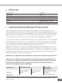
Technical data
Supply voltage
Input current
Signal strength sending
Signal sensitivity
Serial connection
Approval
Marks
7
230 V, 50 Hz
< 1,5 W
> 5 Vpp in 5 Ohm
15 mVpp min, > 50 mVpp bij 120 kHz
9-pin Sub D-connector
EN 60950, EN 55022, EN 55024
CE
Undisturbed functioning of Marmitek X-10 home automation
Electrical equipment and systems can be sensitive to signals from other equipment, which
causes electro magnetic disturbance. In the European Union, countries agreed upon laws for the
immunity (sensitivity) of signals of other equipment as well as equipment emission (disturbance).
When equipment or applications in a certain surrounding comply with the valid standards, they
will not disturb each other's operations (they are called "Electro Magnetic Compatible").
For residential surroundings, where the home automation system Marmitek X-10 is being applied,
the European standard for immunity is standardised in EN 61000-6-1. Equipment that complies
with this standard is resistant to electro magnetic emission of other equipment, which complies
with the European standard EN 61000-6-3 for residential surroundings.
Experience has shown that in domestic surroundings, equipment is being used which has an
EMC-emission level that is above the levels stated in EN 61000-6-3. This equipment can disturb
the correct functioning of the Marmitek X-10-modules. The immunity of the Marmitek X-10 built-in
modules is therefore revaluated and equivalent to EN 61000-6-2 (the more severe European
standard for immunity in industrial surroundings).
Nevertheless, the application area for Marmitek X-10 will remain restricted to residential areas.
Marmitek X-10 is therefore not responsible for the disfunctioning of the Marmitek X-10
system as a consequence of equipment in the building with emission levels that exceed
the maximum allowed levels set as standard for residential, commercial and semiindustrial surroundings stated in EN 61000-6-3.
Application area
Valid European Standard
Marmitek X-10
home automation*
Immunity of equipment
Emission of equipment
Immunity and emission standards
Residential
Commercial
Semi-industrial
61000-6-1
61000-6-3
Compatible/
meets the requirements
* Condition is that the total Marmitek X-10-system is installed in accordance with valid instructions supplied by a certified and trained
Marmitek X-10 dealer.
11
Copyrights
Marmitek is a trademark of Pattitude B.V., CTX35™ is a trademark of Marmitek B.V. All rights reserved. Copyright and all other
proprietary rights in the content (including but not limited to model numbers, software, audio, video, text and photographs) rests
with Marmitek B.V. Any use of the Content, but without limitation, distribution, reproduction, modification, display or transmission
without the prior written consent of Marmitek is strictly prohibited. All copyright and other proprietary notices shall be retained on
all reproductions.
20352 - 20100623