1
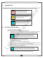
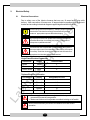
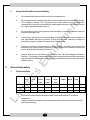
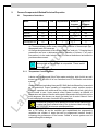
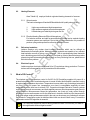
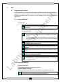
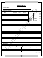
Modular Furnaces
Instruction Manual
Model : LSMF-100 Series
Please read this manual carefully before using the instrument
Labnics Equipment
Table of Content
SR. NO.
CONTENT
PAGE NO.
A.
INTRODUCTION
1
B.
INFORMATION RELATED TO SAFETY
1
1.
Unpacking & Handling of the Furnace
1
2.
Electrical Safety
2
3.
Environmental Safety
3
GENERAL INFORMATION
3
1.
Technical Details
3
2.
Furnace Components & Related Technical Properties
4
2.1
Temperature Controllers
4
2.2
Heating Elements
5
2.3
Refractory Insulation
5
2.4.
Electrical Layout
5
3.
What is PID Control?
5
4.
Points to Take Care While Operating the Furnace
6
5.
Hints
7
5.1.
Programming Techniques
7
5.2.
Maintenance
8
5.3.
Repairs & Replacements
9
5.4
Calibration
10
5.5
After Sales Services
10
Frequently asked questions
10
OPERATING PROPERTIES
11
1.
Electrical & Other Requirements
11
2.
Control Panel
11
C.
6.
D.
E.
SERVICE REPORT
A.
INTRODUCTION
This booklet includes our recommendations, hints and points of notice for you to have a safe and better service
from this equipment. We kindly ask you to carefully read this manual and only then to operate the furnace.
This insignia is used for the purpose of
warning you against risks involved.
Read carefully the notes when this sing is noted.
The insignia is to warn you for any risk of
damage to this equipment.
i
B.
This insignia warns you of the hints to use
this equipment in better terms.
Information Related To Safety
1.
Unpacking and Handling of the Furnace
Before operating the furnace please take note of following points.
• This furnace has been packed to minimize any risk due to transportation. Remove the
packing with care; avoid using any kind of force and removing packing inserts slowly.
i
It is extremely important to remove the packing inserts from
inside the furnace . Operating the furnace without removal
of safety inserts will cause heavy damage on the heating elements.
•
•
•
•
Use furnace base while lifting and carrying the furnace.
Always use two persons to carry.
Always take note of the weight of furnace during placement.
Do not operate the furnace if there is inflammable material around. Ensure that the risk of
fire is non-existent .Do not place the furnace on an inflammable surface.
• Placement should be in a well ventilated room, with no interaction with other sources of
heat. Do not place on an inflammable surface.
i
Air circulation, should be capable enough to remove any gas emission
due to come through the lid or furnace chimney. Almost all gas
emissions during operation can be hazardous for Human health
• Always give space of 30cm around the furnace to enable quick service. Do not close the
vents on the furnace body. These are required to cool down the system.
-1-
2.
Electrical Safety
2.1
Electrical Connections
Due to safety none of the Labnics furnaces that use over 16 amps have a plug while
delivery. Main connection of furnace over 16 amps should be managed through a circuit
breaker and according to electrical diagram supplied together with this manual.
Electrical plugs even at low amperes (< 16amps) are prone to create
electrical arcs. We therefore strongly recommend using a circuit
breaker of appropriate amperes rather than the plug.
Any electrical connection to operate this furnace must be done by
a Qualified Electrician .Accordingly any repairs or maintenance
job requires a qualified technician.
The technician who is responsible of commissioning the furnace is
also responsible to act in accordance the rules of safety of European
Community. Technician is solely responsible of selection and use of
appropriate circuit breaker and earth connections.
Single Phase Electrical Connection
Cable Color
Supply
Terminal Label
Brown
Phase
L
Blue
Neutral
N
Earth
E
Green-Yellow
Triphase Electrical Connection
Line number
Supply
Designation of Lines
1
Phase 1
L1
2
Phase 2
L2
3
Phase 3
L3
4
Neutral
N
Earth
E
Green-Yellow
•
Power supply must be close enough to enable the operator to cut off
power easily in case of emergencies.
•
Mains connection must incorporate an earthed isolating cut off switch.
Never use an electrically conductive tool within the furnace while in
operation
-2-
3.
C.
Human Health and Environmental Safety
1.
Do not operate this furnace while there is any live substance in it.
2.
Do not operate this furnace with flammable, explosive, poisonous etc. materials (Hydrogen,
LPG, Acetylene, Arsenic, TNT, Gunpowder etc.) inside. Labnics does not accept any
responsibility in case of any accident which might happen during any kind of process due to
the usage of materials mentioned above.
3.
Do not contact or get in close proximity with flammable or explosive materials while this
furnace is operating or hot.
4.
If at any times, this furnace is to be used under conditions of hazard to Human health, the
sole responsibility belongs to Operator. During such operation Operator is obliged to
provide the necessary conditions to minimize any risks involved.
5.
If the lid of furnace is to be opened for a short cool down, any risks involved due to hot
discharge of air, belongs solely to Operator. We strongly advice of notification of personnel
around, against risks, to avoid any burns etc.
6.
Labnics furnaces are manufactured in conformity with CE Electromagnetic Emissions
Directive. Even though so electromagnetic emissions can effect some sensitive equipment
such as Hearth Pace Batteries. Any one carrying such batteries should avoid close contact
with this furnace.
General Information
1.
Technical Details
Model
Max.
Cont.
Bore
Heated
Uniform
Ex. Dims.
Apx.
Max.
Temp.
Temp.
Diameter
Length
Length
HxWxD
Weight
Power
(mms)
(mms)
(mms)
Phase
LSMF-100A
1100 C
1050 C
100
500
400
51x34x700
32
1.3
1
LSMF-100B
1100 C
1050 C
150
500
400
51x34x950
41
1.9
1
LSMF-100C
1100 C
1050 C
200
500
400
60x41x700
44
2.5
1
*
The heat up times mentioned are approximate values established at 25°C medium
**
temperature
Labnics is entitled to change the technical properties of the furnaces manufactured at will
and without informing.
-3-
2.
Furnace Components & Related Technical Properties
2.1
Temperature Controllers
Model
Sensitivity
PID
Step definition
Number of
Number of
Programs
Segments
DC1010
1°C
ü
-
-
-
DC1020
1°C
ü
ü
-
1
DC1040
1°C
ü
-
2
2X8
UDC2500
1°C
ü
ü
1
12
DCP100
1°C
ü
ü
8
8X16
Commander 100
1°C
ü
ü
1
4
• Data concerning the Configuration Parameters are placed to controller during set
up. These parameters define many details such definition of thermocouple type,
temperature scale, PID values etc.
• All configuration parameters of the control system are "read only ". Changing these
parameters can have a detrimental effect to operation of furnace. If, any such
intervention is to be made Labnics must be informed beforehand and asked to
provide a written consent.
i
2.1.1
Almost all Controllers employed have a short period of self test
during which any interference is not possible . Please wait till
this test is over .
Temperature Control Systems
Labnics use only Honeywell /Kent Taylor made controllers, both of which are well
known brands in this field. All of our controllers bear CE Certification and reliable
systems.
Almost all the time (excluding Honeywell DC1040) the Auto/Manual key is canceled
on our controllers. Proper operating of temperature control systems requires
automatic operation and auto/manual key simply disables this mode, giving the
whole control to user. Under manual control system is simply an indicator of
temperature and does not function with regard to temperature control which can be
quite dangerous, the furnace can simply get totally out of control. Manual / Auto
mode is displayed on screen of controller during operation.
Auto/Manual (A/M) key, when pressed to function under manual mode
is under total User's manual control. Due to obvious risks involved DO
NOT OPERATE this furnace under Manual Mode.
Labnics employs 6 different control systems for furnaces produced. All controllers
has a PID facility but as the controller gets sophisticated the programming
capacities and number of steps that can be programmed increase, thereby
increasing the performance of the furnace. Details of control systems can be
reached through the catalogue.
-4-
2.2
Heating Elements
Alser Teknik A.Ş employs Kanthal originated heating elements in furnaces .
2.2.1. Wire elements
The basic advantages of Kanthal APM and Kanthal A1 quality elements are:
1.
2.
3.
High creep resistance at high temperatures.
High resistance against corrosive atmospheres.
Limited change of resistivity during service life.
2.2.2. Fibrothal Heating Elements/ Effect of Atmosphere
For Labnics modular and split furnaces Kanthal Fibrothal series modular heating
elements systems are employed. Due to their all round distribution it is possible to
produce quite good temperature uniformity within the furnace.
3.
2.3.
Refractory Insulation
Labnics employs only modern heat insulating materials which can be defined as
fiberboards and insulating bricks. Modern insulation materials are capable of very efficient
heat insulation as well as giving a very low mass . Still at commissioning these materials
emit a disturbing gas which may be felt at only first heat up. Most of these discharge takes
place during tests at manufacturing stage, even so if any felt during first use, please do not
think this to be a problem.
2.4.
Electrical Layout
Labnics employs electrical components fit for CE regulations during production .Furnaces
do have all necessary safety cut off precautions if there need be.
What is PID Control?
The simplest way of temperature control is On/Off. On/Off Controlling supplies full power till a
predetermined Set point is reached and power is turned off after this threshold is reached, turning
on again when temperature drops down. Temperature is never stable, only fluctuating at around the
set point. Due to full power use, temperature over shoot is unavoidable especially at lower
temperatures where heat loss is minimal. PID, Proportional-Integral-Derivative Control systems
supply power as much as necessary and limits applied power as actual temperature gets closer to
set temperature. Microprocessor keeps the temperature rise (heat up) under control through
continuous input measurements and as the difference in between Actual and Set temperatures
gets closer power employed decreases which in the end over shoots are very limited even at lower
temperatures. Temperature control is stabilized after initial over shoot if there is any. For sensitive
temperature control PID algorithm is essential.
PID values are supplied by Labnics during production tests. Do not modify PID data as
this might lead to serious negative results.
-5-
4.
Points to Take Care While Operating the Furnace
1.
Every furnace has a specified maximum temperature and it should never be used over this
temperature.
The heating elements and the concerned insulation are related with furnace
50°C below the maximum temperature to have a longer element life. Never use
a furnace over its designated maximum temperature.
2.
Do not forget to place the (insulating plugs) heat shields to each end of the furnace tube.
''These plugs are not supplied for vertical designs''
3.
Gas feed-in End-Caps are supplied optionally. If supplied, please take note of following
points for placing them onto the ceramic tubes,
• Use the Teflon band supplied to wind 2 times around the tube
• Place the o-ring to its corresponding groove at the end cap
• Place the caps at tube ends
• Tighten the nut& bolts on the End-Caps without applying any torque to the ceramic
tube
4.
Mullite based ceramic tubes are used with standard modular furnaces. These tubes
besides having a satisfactory application temperatures, also exhibit high thermal shock
resistance. As a rule of thumb, larger the dimension of the tube the worse is the thermal
shock resistance. User therefore should always take great care not to heat or to cool down
the tube at high rates.
•
Programming should be applied to manage controlled heating to set temperature and also
controlled cooling is strongly recommended. Heat up rates of less than 8°C/min is strongly
advised.
•
Always avoid removal of any substance within the tube while hot as this will create a sudden
cool down at point of contact. If absolutely necessary, use a insulating sample carrier plate
where the sample is placed upon during heating stage.
•
Intervention into the tube ,placing a sample while hot can also be a reason for cracking, always
use a carrier base plate
•
If relatively large samples are placed within the tube always take care for a slower heat up to
enable a stable heating.
5.
Keep organic solvents and water away from insulation material.
6.
Keep metal slag away from heating elements to avoid a short cut.
7.
Labnics furnaces are not designed for heating food and operator should not use the furnace for
cooking purposes.
8.
Heating elements (Fibrothal Units) usually give a very long service life but are basically for
consumption. They will have to be replaced after a reasonable period of use. Heating elements are
not a part of Warranty which is provided for a period of 2 years.
-6-
5.
Hints
5.1.
Programming Techniques
Labnics supplies the Controller Manuals together with the other documentation Operator is
requested to consult to original manual concerning the controller applied. Nevertheless
following information has the purpose to give operator some info to ease his/her
applications.
5.1.1. Honeywell DC1040
Programming
1.
Press “SET” key once to open Programming page
i
2.
DC1040 has 2 separate programs of 8 steps each. Both programs can be
operated separately.
i
5.1.2
We strongly recommend you to draw the program profile on paper, before
data feed in.
•
Almost all heat up rates can be defined during programming but this
does not necessarily mean that the furnace is capable to achieve that
program.
•
During data feed in, one must consider that the furnace heat up rate will
decrease eventually. Heat up rates of 5-10C0 can be considered
reasonable.
i
If a program is shorter than 8 steps, to end the program output power on
last step should be designated as %0.
i
Once a program is running, the parameters involved can not be
changed.
i
Once the program ends, to start it all over again press ▼ and “SET” keys to
reset.
i
If you are willing to operate your furnace under unprogrammed (open)
mode, you can choose 2 procedures
i
1. Delete all program data
2. Start program by “▲” key and consequently hold it by “▼” key. Now you
can change set point.
Honeywell UDC2500
Programming Hints
UDC 2500 controller has 3 programming modes:
SPRate, SPRamp, SPProg
All can be used as required but SPProg is capable of managing the other two.
i
To run any programming mode, it has to be enabled by pressing either “up”
or “Down” keys. Only one of the modes can be enabled
-7-
Due to cancellation of manual key on display any programming profile has to have
the cooling stage defined as well.
i
Use a paper to draw your program profile before data feed in.
i
•
We advice the PVSTART option to be enabled to ease the running of
program.
While running the program, you will observe the display flashing “RUN”
•
from time to time.
If display key is pressed during a RUN ,various info regarding the
•
program will be displayed.
5.1.3. Honeywell DCP100
DCP100 is capable of 8 programs of 16 steps each. Due to this capacity it is a
complicated system and operator must read the concerned manual.
5.1.4. Kent Taylor Commander100
Commander 100 is capable only of a 4 steps programming. At end of program,
control will return to its normal display and take note of the Set temperature
mentioned. Therefore before running a program always decrease the Set
temperature to room temperature.
i
While a program is running “set temperature” can not be changed
•
Secret Code: A number to hinder any unauthorized entry to configuration levels
(2,3 and 4.levels)
i
Code is “10” .Only after code is fed you car each to 2, 3 and 4th levels
Although possible, do not change any of the parameters Labnics
has configured during set up. Interference with configuration data
might create serious problems. Operator should only change
program data (LEVEL.4)
i
5.2.
Once program data is fed in at LEU4, it will not be lost due to power
cut offs.
Maintenance
1.
2.
Although periodic maintenance is not required if the furnace is operating frequently
it will be wise to clean up the air vent from time to time
For cleaning purposes a wet & soft piece of cloth can be used but do not use any
organic solvents as it may effect the epoxy paint.
-8-
5.3.
Repairs & Replacements
A)
Change of Tube
i
Ceramic tube can be freely changed for MTF series tube furnaces where
Fibrothal heating elements are used.
Please use following procedure when changing tubes for furnaces
Always disengage power before starting the replacement.
1.
Remove the tube when cold (Temp. <45°C), slowly without any contact with
the heating elements.
2.
Replace the new tube without damaging the insulating collars.
3.
Heat the furnace till 900°C.
Change of Fibrothal Series
Since these units arrive ready to use it is somewhat easier to replace than 1200C
standard tube furnaces where heating elements are wound over the ceramic tube.
Always disengage power before starting the replacement and put a mask on that
can filter the insulation powders. It is necessary to open the hind lid the furnace to
change the fibrothal elements.
Note the terminal and cable positions before and remove terminal connections.
Then remove the thermocouple. Remove the earth cable
To removing the
cylindrical case, remove the screws at right and left, beneath case. Open the lids at
sides of furnace case. Remove the steel case from left when looking panel in front of
you. The insulation inside is in fact two half shells and then the fibrothal unit can
easily be reached and changed. Reverse the process after changing the units. In
the mean time you must be careful removing the ceramic tubes, which isolates
resistance wire from outer shell and provide electrical insulation, as these will
exactly required to be replaced while closing the cylindrical case.
During reassembly process one must be careful to connect the correct terminals.
Reheat the Furnace to 900°C.
Do not use insulation that appears loose .Most of the time the very same insulation
can be obtained from local market. We can of course deliver the concerned
insulation whenever requested.
B)
Replacement of Solid State Relay
Always disengage power before opening the back panel. Use proper screw driver
and remove the back panel or control box. Disconnect the relays, taking note of
connection diagram and coloring of wires. Remove the disfunctioning relay using a
screw driver and place the new one to the related rail. Close the back panel and heat
up the furnace till 900°C.
-9-
C)
Replacement of Thermocouple
Always disengage power before opening the back panel. Use proper screw driver.
When there is thermocouple break down, the controller always gives a related
warning (please check the original controller booklet) on the display.
If the thermocouple is placed inside the cylinder shell; remove the back panel of the
furnace. Remove the cables noting the coloring of connecting cable. Remove the
thermocouple slowly taking note not to break the ceramic sheath if there is any.
Reverse the process and heat up the furnace 900°C.
5.4.
Calibration
Depending on using frequency and application temperature, you may require a calibration
of the thermocouple from time to time or even a change of the thermocouple. For K-N type
thermocouples we advice a change for every year. For S or R type thermocouples the useful
life can be much longer for temperatures less than 1500°C. At applications close to 1600°C,
a change of thermocouple every year is also advised.
5.5.
After Sales Services
Labnics Co. manufactures robust furnaces so that after sales are kept at minimum. Even so
we have engineers that will provide you any service you require. Most of the time problems
encountered can quite sufficiently be solved by technical assistance through internet or by
phone. Please always inform of the serial number for better analysis of the problem. For an
easier problem solving please note following ''fault analysis'' questions.
6.
Frequently asked questions /Fault Analysis
1.
Furnace controller does not display when the I/0 switch turned on?
1.1.
Check the Mains supply. Check the voltage present. May be less than 220V
1.2.
Check the fuses on your mains supply.
1.3.
Check the glass fuse at side of furnace; it may be broken during transport.
1.4.
Check the power supply of temperature controller.
1.5.
Check the main fuses, after opening the back panel.
2.
Furnace does not heat up when the "heat" I/0 switches turned on?
The Heat lamp is not operating?
PV value is higher than SP value. Increase the Set temperature.
Heating element may have failed.
Thermocouple may have failed (Controller display must be showing a warning) or the
connection cables may be disconnected. See warnings below.
SSR may have failed and needs replacement.
- 10 -
Model
T/C failure sign
Honeywell DC1010-1020-1040
inIE
Honeywell UDC2500
IN1FL
Honeywell DCP100
IN1FL
Kent Taylor Commander 100
D.
CALL/Err
3.
Display shows a higher temperature than the limits of furnace?
There may be an SSR failure, ON.
Configuration of the controller may have been changed by someone.
4.
Thermocouple shows a low temperature
4.1
The thermocouple may have been shorted or may have been moved from its
original place
4.2
Thermocouple may be reverse connected
4.3
Controller may be have a faulty configuration
Operational Properties
1.
Electrical & Other Requirements
Phase
Volts
Frequency
Medium Temp.
Humidity
Single
220V
50Hz
5°C-40°C
Max.%85
380/220V
50Hz
Triphase
2.
Control panel
Heat lamb
Temp. Controller
O/T alarm relay switch
Heat switch
Power Switch
i
Single phase furnaces have single “heat lamp”
To operate the furnace:
1.
Turn on the Green I/0 switch. This will open the controller panel but the furnace will
not start heating. The purpose of this is to give time to operator to feed in
programming data / set the required temperature etc. without actually the heat up.
2.
To start heating turn on the red “heat” I/0 switch and if all normal, you will observe the
“heat lamps” lighting on and off.
- 11 -
SERVICE REPORT
Tel.No.:
Customer’s Address :
Fax No.:
Weekly Off.:
Dept.:
Contact Person / Designation :
Time
Date
From
To
System
Configuration
Date :
Model
SR. No.
Serial No.
Status : OK
Installation
Not OK
Warranty
Demonstration
Maintenance
Contract
Repairs
Application
Billable
Calibration
Validation
Courtesy
Nature of Problem :
Observation & Action Taken :
Customer’s Remarks :
Parts Replaced :
Parts Recommended / Action Required : Yes
No
Service Engineer’s Name & Signature
Requisition Number :
Customer’s Name, Signature, Date & Stamp
Page ____ Of ____
- 20 -
Labnics Equipment
43040 Christy St., Fremont, CA 94538 USA.
Toll Free : (877) 620 9992
Tel. : (925) 271 4322
Fax : (925) 886 0400
Email : [email protected]
Website : www.labnics.com