1
User Manual
ArmorStart® LT Distributed Motor Controller
Catalog Numbers 290E, 291E, 294E
Important User Information
Because of the variety of uses for the products described in this publication, those responsible for the application and use of
this control equipment must satisfy themselves that all necessary steps have been taken to assure that each application and
use meets all performance and safety requirements, including any applicable laws, regulations, codes and standards.
The illustrations, charts, sample programs and layout examples shown in this guide are intended solely for purposes of
example. Since there are many variables and requirements associated with any particular installation, Rockwell Automation
does not assume responsibility or liability (to include intellectual property liability) for actual use based upon the examples
shown in this publication.
Solid-state equipment has operational characteristics differing from those of electromechanical equipment. Safety
Guidelines for the Application, Installation and Maintenance of Solid State Controls (Publication SGI-1.1 available from your
local Rockwell Automation sales office or online at http://www.rockwellautomation.com/literature/) describes some
important differences between solid-state equipment and hard-wired electromechanical devices. Because of this difference,
and also because of the wide variety of uses for solid-state equipment, all persons responsible for applying this equipment
must satisfy themselves that each intended application of this equipment is acceptable.
In no event will Rockwell Automation, Inc. be responsible or liable for indirect or consequential damages resulting from the
use or application of this equipment.
The examples and diagrams in this manual are included solely for illustrative purposes. Because of the many variables and
requirements associated with any particular installation, Rockwell Automation, Inc. cannot assume responsibility or
liability for actual use based on the examples and diagrams.
No patent liability is assumed by Rockwell Automation, Inc. with respect to use of information, circuits, equipment, or
software described in this manual.
Reproduction of the contents of this manual, in whole or in part, without written permission of Rockwell Automation,
Inc., is prohibited.
Throughout this manual, when necessary, we use notes to make you aware of safety considerations.
WARNING: Identifies information about practices or circumstances that can cause an explosion in a hazardous environment,
which may lead to personal injury or death, property damage, or economic loss.
ATTENTION: Identifies information about practices or circumstances that can lead to personal injury or death, property
damage, or economic loss. Attentions help you identify a hazard, avoid a hazard, and recognize the consequence.
SHOCK HAZARD: Labels may be on or inside the equipment, for example, a drive or motor, to alert people that dangerous
voltage may be present.
BURN HAZARD: Labels may be on or inside the equipment, for example, a drive or motor, to alert people that surfaces may
reach dangerous temperatures.
IMPORTANT
Identifies information that is critical for successful application and understanding of the product.
General Precautions
In addition to the precautions listed throughout this manual, the following statements, which are general to the system,
must be read and understood.
ATTENTION: This manual is intended for qualified service personnel responsible for setting up and servicing these devices. The
user must have previous experience with and a basic understanding of electrical terminology, configuration procedures,
required equipment, and safety precautions.
WARNING: The National Electrical Code (NEC), NFPA79, and any other governing regional or local code will overrule the
information in this manual. Rockwell Automation cannot assume responsibility for the compliance or proper installation of the
ArmorStart LT or associated equipment. A hazard of personal injury and/or equipment damage exists if codes are ignored
during installation.
ATTENTION: The controller contains ESD (electrostatic discharge) sensitive parts and assemblies. Static control precautions are
required when installing, testing, servicing, or repairing the assembly. Component damage may result if ESD control
procedures are not followed. If you are not familiar with static control procedures, refer to Publication 8000-4.5.2, Guarding
against Electrostatic Discharge, or any other applicable ESD protection handbooks.
ATTENTION: Only personnel familiar with the controller and associated machinery should plan or implement the installation,
startup, and subsequent maintenance of the system. Failure to do this may result in personal injury and/or equipment
damage.
Precautions for Bulletin 294E Applications
ATTENTION: Only qualified personnel familiar with adjustable frequency AC drives and associated machinery should plan or
implement the installation, startup, and subsequent maintenance of the system. Failure to do this may result in personal injury
and/or equipment damage.
Rockwell Automation Publication 290E-UM001B-EN-P - June 2012
3
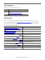
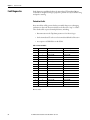
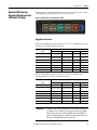
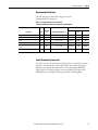
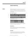
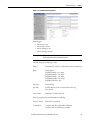
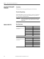
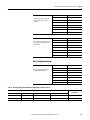
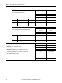
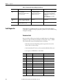
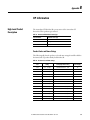
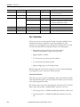
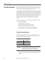
Software Requirements
The table lists the versions of software that are required.
Software
Version
RSLinx Classic
2.56 or later
RSLogix 5000
17.01 or later
Download the most current version of the Add-On Profile from
http://www.rockwellautomation.com/support/downloads.html.
BOOTP/DHCP
Version 2.3 or later
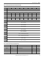
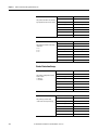
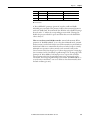
Additional Resources
These documents and websites contain additional information concerning related Rockwell Automation products.
You can view or download publications at http:/www.rockwellautomation.com/literature/. To order paper copies of
technical documentation, contact your local Allen-Bradley distributor or Rockwell Automation sales representative.
Table 1 - Rockwell Automation Industrial Network Resources
Resource
Description
http://ab.rockwellautomation.com/Networks-and-Communications
Rockwell Automation networks and communication website
http://ab.rockwellautomation.com/Networks-and-Communications/Ethernet-IPNetwork
Rockwell Automation EtherNet/IP website
http://www.rockwellautomation.com/services/networks/
http://www.rockwellautomation.com/services/security/
Rockwell Automation network and security services websites
http://www.ab.com/networks/architectures.html
Education series webcasts for IT and controls professionals
EtherNet/IP Embedded Switch Technology Application Guide, Publication ENET-AP005
Describes how to install, configure, and maintain linear and device-level Ring (DLR)
networks using Rockwell Automation EtherNet/IP devices with embedded switch
technology.
EtherNet/IP Network Configuration User Manual, Publication ENET-UM001
Describes how to configure and use EtherNet/IP communication modules with a
Logix5000 controller and communicate with various devices on the Ethernet network.
EtherNet Design Consideration, Publication ENET-RM002A-EN-P
Provides details on ethernet design and infrastructure.
EtherNet/IP Modules in Logix5000 Control Systems User Manual, Publication ENET-UM001 Provides details about how to configure your module.
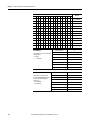
4
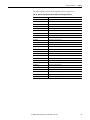
EtherNet/IP Embedded Switch Technology Application Guide, Publication ENET-AP005
Provides information about using products with embedded switch technology to
construct networks with linear and ring topologies.
EtherNet/IP Industrial Protocol White Paper, Publication ENET-WP001
Describes how to implement services and data objects on a TCP/UDP/IP based Ethernet
network.
Industrial Automation Wiring and Grounding Guidelines, Publication 1770-4.1
Provides general guidelines for installing a Rockwell Automation industrial system.
Wiring and Grounding Guidelines, (PWM) AC Drives, Publication DRIVES-IN001
Describes wiring and grounding guidelines for Pulse Width Modulated (PWM) AC Drives
Product Certifications website,
http://www.rockwellautomation.com/products/certification/
Provides declarations of conformity, certificates, and other certification details.
Rockwell Automation Publication 290E-UM001B-EN-P - June 2012
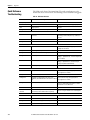
Table 2 - ODVA Resources
Resource
Description
http://www.odva.org/
Open DeviceNet Vendors Association (ODVA) website
http://www.odva.org/default.aspx?tabid=54
The CIP Advantage website
• CIP features and benefits
• How to get started
Ethernet Media Planning and Installation Manual, ODVA publication
http://www.odva.org/Portals/0/Library/Publications_Numbered/
PUB00148R0_EtherNetIP_Media_Planning_and_Installation_Manual.pdf
Describes the required media components and how to plan for, install, verify,
troubleshoot, and certify an Ethernet network.
Network Infrastructure for EtherNet/IP: Introduction and Considerations, ODVA publication Provides an overview of the technologies used in EtherNet/IP networks and provides
guidelines for deploying infrastructure devices in EtherNet/IP networks.
http://www.odva.org/Portals/0/Library/Publications_Numbered/
PUB00035R0_Infrastructure_Guide.pdf
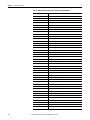
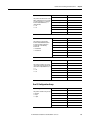
Table 3 - Product Selection Resources
Resource
Description
Industrial Controls catalog website,
http://www.ab.com/catalogs/
Industrial Controls catalog website
ArmorStart LT Distributed Motor Controller Selection Guide, Publication 290-SG001
Product selection guide
Table 4 - Cisco and Rockwell Automation Alliance Resources
Resource
Description
http://www.ab.com/networks/architectures.html
Rockwell Automation and Cisco Systems reference architecture website
Converged Plantwide Ethernet (CPwE) Design and Implementation Guide, Publication
ENET-TD001
Represents a collaborative development effort from Rockwell Automation and Cisco
Systems. The design guide is built on, and adds to, design guidelines from the Cisco
Ethernet-to-the-Factory (EttF) solution and the Rockwell Automation Integrated
Architecture. The design guide focuses on the manufacturing industry.
Rockwell Automation Support
Rockwell Automation provides technical information on the Web to assist you in using its products. At
http://www.rockwellautomation.com/support/, you can find technical manuals, a knowledge base of FAQs, technical
and application notes, sample code and links to software service packs, and a MySupport feature that you can customize
to make the best use of these tools.
Installation Assistance
If you experience a problem within the first 24 hours of installation, contact Customer Support.
United States or Canada
1.440.646.3434
Outside United States or
Canada
Use the Worldwide Locator at http://www.rockwellautomation.com/support/
americas/phone_en.html, or contact your local Rockwell Automation representative.
Rockwell Automation Publication 290E-UM001B-EN-P - June 2012
5
New Product Satisfaction Return
Rockwell Automation tests all of its products to ensure that they are fully operational when shipped from the
manufacturing facility. However, if your product is not functioning and needs to be returned, follow these procedures.
6
United States
Contact your distributor. You must provide a Customer Support case number (call the
phone number above to obtain one) to your distributor to complete the return process.
Outside United States
Please contact your local Rockwell Automation representative for the return
procedure.
Rockwell Automation Publication 290E-UM001B-EN-P - June 2012
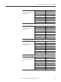
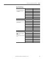
Summary of Changes
New and Updated
Information
This table contains the changes made to this revision.
Topic
Page
Added source brake and IPS specifications
Various
Rockwell Automation Publication 290E-UM001B-EN-P - June 2012
7
Summary of Changes
Notes:
8
Rockwell Automation Publication 290E-UM001B-EN-P - June 2012
Preface
European Communities (EC)
Directive Compliance
If this product has the CE mark it is approved for installation within the
European Union and European Economic Area (EEA). It has been designed and
tested to meet the following directives.
Low Voltage and EMC
Directives
This product is tested to meet the European Union (EU) Council 2006/95/EC
Low Voltage Directive and the EU Council 2004/108/EC Electromagnetic
Compatibility (EMC) Directive by applying the following standard(s):
• Bulletin 290E_/291E_: EN 60947-4-1 — Low-voltage switchgear and
controlgear — Part 4-1: Contactors and motor-starters — Electromechanical
contactors and motor-starters.
• Bulletin 294E_: EN 61800-3 — Adjustable speed electronic power drive
systems — Part 3: EMC product standard including specific test methods
EN 61800-5-1:2003 — Adjustable speed electrical power drive systems —
Part 5-1: Safety requirements — Electrical, thermal and energy.
This product is intended for use in an industrial environment.
Rockwell Automation Publication 290E-UM001B-EN-P - June 2012
9
Preface
Introduction
10
The ArmorStart LT is an integrated, pre-engineered, motor starting solution
designed for use in material handling applications. ArmorStart LT is the latest
addition to the ArmorStart portfolio. ArmorStart LT is a leader in the market
place given its compact size and high performance features in network, I/O, and
motor control. This manual will guide you through the features and functionality
when installing the product. Thank you for choosing ArmorStart LT for your
distributed motor control needs. If you have any questions please refer to the
“Support Section” for contact information.
Rockwell Automation Publication 290E-UM001B-EN-P - June 2012
Table of Contents
Important User Information . . . . . . . . . . . . . . . . . . . . . . . . . . . . . . . . . . . . . . . 2
General Precautions . . . . . . . . . . . . . . . . . . . . . . . . . . . . . . . . . . . . . . . . . . . . . . . . 3
Software Requirements . . . . . . . . . . . . . . . . . . . . . . . . . . . . . . . . . . . . . . . . . . . . . 4
Additional Resources . . . . . . . . . . . . . . . . . . . . . . . . . . . . . . . . . . . . . . . . . . . . . . . 4
Rockwell Automation Support . . . . . . . . . . . . . . . . . . . . . . . . . . . . . . . . . . . . . . 5
Installation Assistance . . . . . . . . . . . . . . . . . . . . . . . . . . . . . . . . . . . . . . . . . . . . . . 5
New Product Satisfaction Return . . . . . . . . . . . . . . . . . . . . . . . . . . . . . . . . . . . . 6
Summary of Changes
New and Updated Information. . . . . . . . . . . . . . . . . . . . . . . . . . . . . . . . . . . . . . 7
Preface
European Communities (EC) Directive Compliance . . . . . . . . . . . . . . . . . 9
Low Voltage and EMC Directives . . . . . . . . . . . . . . . . . . . . . . . . . . . . . . . . . . 9
Introduction . . . . . . . . . . . . . . . . . . . . . . . . . . . . . . . . . . . . . . . . . . . . . . . . . . . . . . 10
Chapter 1
Product Overview
Description . . . . . . . . . . . . . . . . . . . . . . . . . . . . . . . . . . . . . . . . . . . . . . . . . . . . . . 17
Features . . . . . . . . . . . . . . . . . . . . . . . . . . . . . . . . . . . . . . . . . . . . . . . . . . . . . . . . . 18
Feature Description . . . . . . . . . . . . . . . . . . . . . . . . . . . . . . . . . . . . . . . . . . . . . . 19
Standard Features Across Product Familly . . . . . . . . . . . . . . . . . . . . . . 19
Network Options . . . . . . . . . . . . . . . . . . . . . . . . . . . . . . . . . . . . . . . . . . . . . . . . 20
Factory Installed Options . . . . . . . . . . . . . . . . . . . . . . . . . . . . . . . . . . . . . . . . . 22
ArmorStart LT Characteristics Bulletin 290E/291E . . . . . . . . . . . . . . . . 23
Catalog Number Explanation Bulletin 290E/291E. . . . . . . . . . . . . . . . . . 24
ArmorStart LT Characteristics Bulletin 294E . . . . . . . . . . . . . . . . . . . . . . 25
Catalog Number Explanation Bulletin 294E. . . . . . . . . . . . . . . . . . . . . . . . . 26
Basic Operation . . . . . . . . . . . . . . . . . . . . . . . . . . . . . . . . . . . . . . . . . . . . . . . . . . . 27
Group Motor Installations for USA and Canada Markets . . . . . . . . .27
Control Circuit . . . . . . . . . . . . . . . . . . . . . . . . . . . . . . . . . . . . . . . . . . . . . . . 27
Motor Circuit . . . . . . . . . . . . . . . . . . . . . . . . . . . . . . . . . . . . . . . . . . . . . . . . . 29
Local I/O . . . . . . . . . . . . . . . . . . . . . . . . . . . . . . . . . . . . . . . . . . . . . . . . . . . . . 29
Overload Protection . . . . . . . . . . . . . . . . . . . . . . . . . . . . . . . . . . . . . . . . . . . 30
Mode of Operation Bulletin 290E/291E . . . . . . . . . . . . . . . . . . . . . . . . . . . .30
Full-Voltage Start. . . . . . . . . . . . . . . . . . . . . . . . . . . . . . . . . . . . . . . . . . . . . . 30
Mode of Operation Bulletin 294E . . . . . . . . . . . . . . . . . . . . . . . . . . . . . . . . . . 31
Sensorless Vector Performance. . . . . . . . . . . . . . . . . . . . . . . . . . . . . . . . . . 31
Status LEDs and Reset . . . . . . . . . . . . . . . . . . . . . . . . . . . . . . . . . . . . . . . . . . . . . 32
Electronic Data Sheet (EDS) . . . . . . . . . . . . . . . . . . . . . . . . . . . . . . . . . . . 33
Fault Diagnostics. . . . . . . . . . . . . . . . . . . . . . . . . . . . . . . . . . . . . . . . . . . . . . . . . . 34
Protection Faults . . . . . . . . . . . . . . . . . . . . . . . . . . . . . . . . . . . . . . . . . . . . . . 34
Optional HOA Selector Keypad. . . . . . . . . . . . . . . . . . . . . . . . . . . . . . . . . . . . 35
Keypad Local Control . . . . . . . . . . . . . . . . . . . . . . . . . . . . . . . . . . . . . . . . . 35
Optional HOA Keypad Configuration (Bulletin 290E/291E only). . . .35
Rockwell Automation Publication 290E-UM001B-EN-P - June 2012
11
Table of Contents
Optional HOA Selector Keypad
with Jog Function(Bulletin 294E only). . . . . . . . . . . . . . . . . . . . . . . . . . . . . . 37
Keypad Local Control . . . . . . . . . . . . . . . . . . . . . . . . . . . . . . . . . . . . . . . . . 37
Keypad and HOA Disable Parameter. . . . . . . . . . . . . . . . . . . . . . . . . . . . 38
Source Brake Contactor and Connector (Bulletin 294E only) . . . . . . . . .38
Chapter 2
Installation and Wiring
12
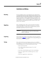
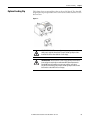
Receiving . . . . . . . . . . . . . . . . . . . . . . . . . . . . . . . . . . . . . . . . . . . . . . . . . . . . . . . . .39
Unpacking. . . . . . . . . . . . . . . . . . . . . . . . . . . . . . . . . . . . . . . . . . . . . . . . . . . . . . . .39
Inspecting . . . . . . . . . . . . . . . . . . . . . . . . . . . . . . . . . . . . . . . . . . . . . . . . . . . . . . . .39
Storing . . . . . . . . . . . . . . . . . . . . . . . . . . . . . . . . . . . . . . . . . . . . . . . . . . . . . . . . . . . 39
Installation Precautions. . . . . . . . . . . . . . . . . . . . . . . . . . . . . . . . . . . . . . . . . . . .40
Precautions for Bulletin 290E/291E Applications. . . . . . . . . . . . . . . . . . . .40
Precautions for Bulletin 294E Applications. . . . . . . . . . . . . . . . . . . . . . . . . . 40
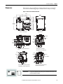
Dimensions. . . . . . . . . . . . . . . . . . . . . . . . . . . . . . . . . . . . . . . . . . . . . . . . . . . . . . .40
Bulletin 290E/291E . . . . . . . . . . . . . . . . . . . . . . . . . . . . . . . . . . . . . . . . . . .41
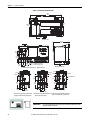
Bulletin 294E . . . . . . . . . . . . . . . . . . . . . . . . . . . . . . . . . . . . . . . . . . . . . . . . . 42
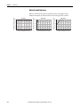
ArmorStart LT Gland Plate Matrix . . . . . . . . . . . . . . . . . . . . . . . . . . . . . 43
Connection Locations . . . . . . . . . . . . . . . . . . . . . . . . . . . . . . . . . . . . . . . . . . . . . 43
Internal Power, Control, and Ground Locations . . . . . . . . . . . . . . . . .43
Gland Connection. . . . . . . . . . . . . . . . . . . . . . . . . . . . . . . . . . . . . . . . . . . . .44
Wiring Terminal Detail. . . . . . . . . . . . . . . . . . . . . . . . . . . . . . . . . . . . . . . . . . . .45
Branch Circuit Protection . . . . . . . . . . . . . . . . . . . . . . . . . . . . . . . . . . . . . . . . .46
Simple System Design . . . . . . . . . . . . . . . . . . . . . . . . . . . . . . . . . . . . . . . . . . . . . 47
ArmorConnect Power . . . . . . . . . . . . . . . . . . . . . . . . . . . . . . . . . . . . . . . . . . . . .48
ArmorConnect Cable Ratings . . . . . . . . . . . . . . . . . . . . . . . . . . . . . . . . . . . . . .49
Branch Circuit Protection Requirements for ArmorConnect
Three-Phase Power Media. . . . . . . . . . . . . . . . . . . . . . . . . . . . . . . . . . . . . .49
Electrical Wiring . . . . . . . . . . . . . . . . . . . . . . . . . . . . . . . . . . . . . . . . . . . . . . . . . .50
Group Motor Installations for USA and Canada Markets . . . . . . . . . . . .55
Wiring . . . . . . . . . . . . . . . . . . . . . . . . . . . . . . . . . . . . . . . . . . . . . . . . . . . . . . . . . . . 55
Cable Workmanship Guidelines . . . . . . . . . . . . . . . . . . . . . . . . . . . . . . . .55
Service Space . . . . . . . . . . . . . . . . . . . . . . . . . . . . . . . . . . . . . . . . . . . . . . . . . . 56
Hand Operation (HOA) Considerations . . . . . . . . . . . . . . . . . . . . . . . . 56
General Wiring Considerations . . . . . . . . . . . . . . . . . . . . . . . . . . . . . . . . . . . . 56
Grounding. . . . . . . . . . . . . . . . . . . . . . . . . . . . . . . . . . . . . . . . . . . . . . . . . . . . . . . . 57
Grounding Safety Grounds . . . . . . . . . . . . . . . . . . . . . . . . . . . . . . . . . . . . . 57
Grounding PE or Ground . . . . . . . . . . . . . . . . . . . . . . . . . . . . . . . . . . . . . . 57
Grounding Motors . . . . . . . . . . . . . . . . . . . . . . . . . . . . . . . . . . . . . . . . . . . . 57
Power Distribution. . . . . . . . . . . . . . . . . . . . . . . . . . . . . . . . . . . . . . . . . . . . . . . . 58
Delta/Wye with Grounded Wye Neutral . . . . . . . . . . . . . . . . . . . . . . . . 58
AC Line Voltage . . . . . . . . . . . . . . . . . . . . . . . . . . . . . . . . . . . . . . . . . . . . . . . . . .58
Line Reactor . . . . . . . . . . . . . . . . . . . . . . . . . . . . . . . . . . . . . . . . . . . . . . . . . . . . . . 58
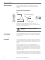
Bulletin 294E Motor Cable Considerations . . . . . . . . . . . . . . . . . . . . . . . . .59
Unshielded Cable . . . . . . . . . . . . . . . . . . . . . . . . . . . . . . . . . . . . . . . . . . . . . 59
Shielded Cable . . . . . . . . . . . . . . . . . . . . . . . . . . . . . . . . . . . . . . . . . . . . . . . . 60
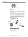
Recommended Cable Connectors/Glands . . . . . . . . . . . . . . . . . . . . . . .60
Rockwell Automation Publication 290E-UM001B-EN-P - June 2012
Table of Contents
Recommended Cord Grips . . . . . . . . . . . . . . . . . . . . . . . . . . . . . . . . . . . . .61
Shield Terminating Connectors . . . . . . . . . . . . . . . . . . . . . . . . . . . . . . . . 61
Electromagnetic Compatibility (EMC) . . . . . . . . . . . . . . . . . . . . . . . . . . . . . 62
General Notes (Bulletin 294E only) . . . . . . . . . . . . . . . . . . . . . . . . . . . . .62
Ethernet, DeviceNet, and I/O Connections . . . . . . . . . . . . . . . . . . . . . . . . . 63
ArmorConnect Power Media Receptacles . . . . . . . . . . . . . . . . . . . . . . . . . . . 64
Optional Locking Clip. . . . . . . . . . . . . . . . . . . . . . . . . . . . . . . . . . . . . . . . . . . . . 65
Chapter 3
Product Commissioning
IP Address . . . . . . . . . . . . . . . . . . . . . . . . . . . . . . . . . . . . . . . . . . . . . . . . . . . . . . . .67
Gateway Address . . . . . . . . . . . . . . . . . . . . . . . . . . . . . . . . . . . . . . . . . . . . . . 67
Subnet Mask . . . . . . . . . . . . . . . . . . . . . . . . . . . . . . . . . . . . . . . . . . . . . . . . . . 67
Configuring EtherNet/IP Address. . . . . . . . . . . . . . . . . . . . . . . . . . . . . . . . . . 68
Manually Configure the Network Address Switches . . . . . . . . . . . . . .68
Static Address Alternative . . . . . . . . . . . . . . . . . . . . . . . . . . . . . . . . . . . . . .69
Using the Rockwell Automation BootP/DHCP Utility . . . . . . . . . . . . . .69
Save the Relation List . . . . . . . . . . . . . . . . . . . . . . . . . . . . . . . . . . . . . . . . . .72
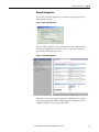
Embedded Web Server . . . . . . . . . . . . . . . . . . . . . . . . . . . . . . . . . . . . . . . . . . . . 74
Network Configuration. . . . . . . . . . . . . . . . . . . . . . . . . . . . . . . . . . . . . . . . 75
Parameter Configuration. . . . . . . . . . . . . . . . . . . . . . . . . . . . . . . . . . . . . . . 76
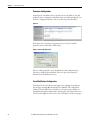
E-mail Notification Configuration . . . . . . . . . . . . . . . . . . . . . . . . . . . . . . 76
How to Add a New Module Using the Add-On Profile. . . . . . . . . . . . . . . 78
Electronic Keying. . . . . . . . . . . . . . . . . . . . . . . . . . . . . . . . . . . . . . . . . . . . . . 80
Connections . . . . . . . . . . . . . . . . . . . . . . . . . . . . . . . . . . . . . . . . . . . . . . . . . . 81
Configured By . . . . . . . . . . . . . . . . . . . . . . . . . . . . . . . . . . . . . . . . . . . . . . . . 81
HOA Keypad Option. . . . . . . . . . . . . . . . . . . . . . . . . . . . . . . . . . . . . . . . . . 82
Source Brake Electro-Mehanical Brake Option. . . . . . . . . . . . . . . . . . . 82
User Configurable I/O. . . . . . . . . . . . . . . . . . . . . . . . . . . . . . . . . . . . . . . . . 82
RSLogix 5000 Add-On Profile . . . . . . . . . . . . . . . . . . . . . . . . . . . . . . . . . . . . . 83
Auto-Generated Tags . . . . . . . . . . . . . . . . . . . . . . . . . . . . . . . . . . . . . . . . . . 85
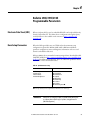
Chapter 4
Bulletin 290E/291E/294E
Programmable Parameters
Electronic Data Sheet (EDS) . . . . . . . . . . . . . . . . . . . . . . . . . . . . . . . . . . . . . . . 99
Basic Setup Parameters . . . . . . . . . . . . . . . . . . . . . . . . . . . . . . . . . . . . . . . . . . . .99
Parameter Groups . . . . . . . . . . . . . . . . . . . . . . . . . . . . . . . . . . . . . . . . . . . . . . . .100
ArmorStart LT EtherNet/IP Parameters . . . . . . . . . . . . . . . . . . . . . . . . . . .102
Introduction . . . . . . . . . . . . . . . . . . . . . . . . . . . . . . . . . . . . . . . . . . . . . . . . . . . . .102
Parameter Programming . . . . . . . . . . . . . . . . . . . . . . . . . . . . . . . . . . . . . . . . . .102
Bulletin 290E/291E . . . . . . . . . . . . . . . . . . . . . . . . . . . . . . . . . . . . . . . . . . . . . .102
Basic Status Group . . . . . . . . . . . . . . . . . . . . . . . . . . . . . . . . . . . . . . . . . . . . . . .102
Trip Status Group . . . . . . . . . . . . . . . . . . . . . . . . . . . . . . . . . . . . . . . . . . . .107
Basic Configuration Group. . . . . . . . . . . . . . . . . . . . . . . . . . . . . . . . . . . .111
Starter Protection Group. . . . . . . . . . . . . . . . . . . . . . . . . . . . . . . . . . . . . .112
User I/O Configuration Group. . . . . . . . . . . . . . . . . . . . . . . . . . . . . . . .115
Miscellaneous Configuration Group . . . . . . . . . . . . . . . . . . . . . . . . . . .119
Advanced Configuration . . . . . . . . . . . . . . . . . . . . . . . . . . . . . . . . . . . . . .121
Rockwell Automation Publication 290E-UM001B-EN-P - June 2012
13
Table of Contents
Bulletin 294E . . . . . . . . . . . . . . . . . . . . . . . . . . . . . . . . . . . . . . . . . . . . . . . . . . . .124
Basic Status Group . . . . . . . . . . . . . . . . . . . . . . . . . . . . . . . . . . . . . . . . . . .124
Trip Status Group . . . . . . . . . . . . . . . . . . . . . . . . . . . . . . . . . . . . . . . . . . . .129
Motor and Control Group . . . . . . . . . . . . . . . . . . . . . . . . . . . . . . . . . . . .133
Speed Control Group . . . . . . . . . . . . . . . . . . . . . . . . . . . . . . . . . . . . . . . . .135
Starter Protection Group. . . . . . . . . . . . . . . . . . . . . . . . . . . . . . . . . . . . . .138
User I/O Configuration Group. . . . . . . . . . . . . . . . . . . . . . . . . . . . . . . .140
Miscellaneous Configuration Group . . . . . . . . . . . . . . . . . . . . . . . . . . .145
Advanced Configuration . . . . . . . . . . . . . . . . . . . . . . . . . . . . . . . . . . . . . .146
Chapter 5
Diagnostics
Overview . . . . . . . . . . . . . . . . . . . . . . . . . . . . . . . . . . . . . . . . . . . . . . . . . . . . . . . .157
Status LEDs and Reset . . . . . . . . . . . . . . . . . . . . . . . . . . . . . . . . . . . . . . . . . . . .157
Fault Diagnostics. . . . . . . . . . . . . . . . . . . . . . . . . . . . . . . . . . . . . . . . . . . . . . . . .158
Protection Faults . . . . . . . . . . . . . . . . . . . . . . . . . . . . . . . . . . . . . . . . . . . . .158
Quick Reference Troubleshooting . . . . . . . . . . . . . . . . . . . . . . . . . . . . . . . . .160
Fault LED Indications . . . . . . . . . . . . . . . . . . . . . . . . . . . . . . . . . . . . . . . . . . . .161
Bulletin 290E/291E Faults . . . . . . . . . . . . . . . . . . . . . . . . . . . . . . . . . . . .161
Bulletin 294E Faults . . . . . . . . . . . . . . . . . . . . . . . . . . . . . . . . . . . . . . . . . .163
Chapter 6
Specifications
Bulletin 290E/291E . . . . . . . . . . . . . . . . . . . . . . . . . . . . . . . . . . . . . . . . . . . . . .165
Motor Overload Trip Curves. . . . . . . . . . . . . . . . . . . . . . . . . . . . . . . . . . . . . .170
Bulletin 100-K/104-K Life-Load Curves . . . . . . . . . . . . . . . . . . . . . . . . . . .171
Bulletin 294E . . . . . . . . . . . . . . . . . . . . . . . . . . . . . . . . . . . . . . . . . . . . . . . . . . . .172
Motor Overload Trip Curves. . . . . . . . . . . . . . . . . . . . . . . . . . . . . . . . . . . . . .178
Appendix A
Appplying More Than One
ArmorStart LT Motor Controller
in a Single Branch Circuit
on Industrial Machinery
Introduction . . . . . . . . . . . . . . . . . . . . . . . . . . . . . . . . . . . . . . . . . . . . . . . . . . . . .179
ArmorStart LT Product Family . . . . . . . . . . . . . . . . . . . . . . . . . . . . . . . . . . .180
Multiple-Motor Branch Circuits and Motor Controllers Listed
for Grooup Installation – General . . . . . . . . . . . . . . . . . . . . . . . . . . . . . . . . .181
Maximum Fuse Ampere Rating According to 7.2.10.4(1)
and 7.2.10.4(2). . . . . . . . . . . . . . . . . . . . . . . . . . . . . . . . . . . . . . . . . . . . . . . . . . .183
Complete Text . . . . . . . . . . . . . . . . . . . . . . . . . . . . . . . . . . . . . . . . . . . . . . .183
Explanatory Example . . . . . . . . . . . . . . . . . . . . . . . . . . . . . . . . . . . . . . . . . . . . .185
Input and Output Conductors of Bulletin 290E and 291E
Controllers (a) . . . . . . . . . . . . . . . . . . . . . . . . . . . . . . . . . . . . . . . . . . . . . . . . . . .191
Input and Output Conductors of Bulletin 294E Controllers (b) . . . . .191
Combined Load Conductors (c). . . . . . . . . . . . . . . . . . . . . . . . . . . . . . . . . . .191
Appendix B
CIP Information
14
High Level Description . . . . . . . . . . . . . . . . . . . . . . . . . . . . . . . . . . . . . . . . . . .193
Product Code and Name Strings . . . . . . . . . . . . . . . . . . . . . . . . . . . . . . .193
CIP Explicit Connection Behavior. . . . . . . . . . . . . . . . . . . . . . . . . . . . . . . . .194
Rockwell Automation Publication 290E-UM001B-EN-P - June 2012
Table of Contents
EDS Files . . . . . . . . . . . . . . . . . . . . . . . . . . . . . . . . . . . . . . . . . . . . . . . . . . . .194
CIP Object Requirements. . . . . . . . . . . . . . . . . . . . . . . . . . . . . . . . . . . . . . . . .194
Identity Object. . . . . . . . . . . . . . . . . . . . . . . . . . . . . . . . . . . . . . . . . . . . . . . . . . .195
CLASS CODE 0x0001 . . . . . . . . . . . . . . . . . . . . . . . . . . . . . . . . . . . . . . .195
Message Router . . . . . . . . . . . . . . . . . . . . . . . . . . . . . . . . . . . . . . . . . . . . . . . . . .196
CLASS CODE 0x0002 . . . . . . . . . . . . . . . . . . . . . . . . . . . . . . . . . . . . . . .196
Assembly Object . . . . . . . . . . . . . . . . . . . . . . . . . . . . . . . . . . . . . . . . . . . . . . . . .196
CLASS CODE 0x0004 . . . . . . . . . . . . . . . . . . . . . . . . . . . . . . . . . . . . . . .196
I/O Assemblies . . . . . . . . . . . . . . . . . . . . . . . . . . . . . . . . . . . . . . . . . . . . . . .197
Connection Manager Object . . . . . . . . . . . . . . . . . . . . . . . . . . . . . . . . . . . . . .203
CLASS CODE 0x0006 . . . . . . . . . . . . . . . . . . . . . . . . . . . . . . . . . . . . . . .203
Class 1 Connections . . . . . . . . . . . . . . . . . . . . . . . . . . . . . . . . . . . . . . . . . .204
Class 3 Connections . . . . . . . . . . . . . . . . . . . . . . . . . . . . . . . . . . . . . . . . . .205
Discrete Input Point Object. . . . . . . . . . . . . . . . . . . . . . . . . . . . . . . . . . . . . . .206
CLASS CODE 0x0008 . . . . . . . . . . . . . . . . . . . . . . . . . . . . . . . . . . . . . . .206
Discrete Output Point Object . . . . . . . . . . . . . . . . . . . . . . . . . . . . . . . . . . . . .206
CLASS CODE 0x0009 . . . . . . . . . . . . . . . . . . . . . . . . . . . . . . . . . . . . . . .206
Discrete Output Point Object Special Requirements . . . . . . . . . . . .207
Analog Input Point Object. . . . . . . . . . . . . . . . . . . . . . . . . . . . . . . . . . . . . . . .211
CLASS CODE 0x000A. . . . . . . . . . . . . . . . . . . . . . . . . . . . . . . . . . . . . . .211
Analog Output Point Object . . . . . . . . . . . . . . . . . . . . . . . . . . . . . . . . . . . . . .211
CLASS CODE 0x000B . . . . . . . . . . . . . . . . . . . . . . . . . . . . . . . . . . . . . . .211
Parameter Object . . . . . . . . . . . . . . . . . . . . . . . . . . . . . . . . . . . . . . . . . . . . . . . .212
CLASS CODE 0x000F . . . . . . . . . . . . . . . . . . . . . . . . . . . . . . . . . . . . . . .212
Parameter Group Object. . . . . . . . . . . . . . . . . . . . . . . . . . . . . . . . . . . . . . . . . .213
CLASS CODE 0x0010 . . . . . . . . . . . . . . . . . . . . . . . . . . . . . . . . . . . . . . .213
Discrete Input Group Object. . . . . . . . . . . . . . . . . . . . . . . . . . . . . . . . . . . . . .214
CLASS CODE 0x001D . . . . . . . . . . . . . . . . . . . . . . . . . . . . . . . . . . . . . .214
Discrete Output Group Object . . . . . . . . . . . . . . . . . . . . . . . . . . . . . . . . . . . .214
CLASS CODE 0x001E . . . . . . . . . . . . . . . . . . . . . . . . . . . . . . . . . . . . . . .214
Control Supervisor Object . . . . . . . . . . . . . . . . . . . . . . . . . . . . . . . . . . . . . . . .215
CLASS CODE 0x0029 . . . . . . . . . . . . . . . . . . . . . . . . . . . . . . . . . . . . . . .215
Overload Object . . . . . . . . . . . . . . . . . . . . . . . . . . . . . . . . . . . . . . . . . . . . . . . . .216
CLASS CODE 0x002C. . . . . . . . . . . . . . . . . . . . . . . . . . . . . . . . . . . . . . .216
Device Level Ring (DLR) Object . . . . . . . . . . . . . . . . . . . . . . . . . . . . . . . . . .217
CLASS CODE 0x0047 . . . . . . . . . . . . . . . . . . . . . . . . . . . . . . . . . . . . . . .217
Extended Device Object . . . . . . . . . . . . . . . . . . . . . . . . . . . . . . . . . . . . . . . . . .217
CLASS CODE 0x0064 . . . . . . . . . . . . . . . . . . . . . . . . . . . . . . . . . . . . . . .217
DPI Fault Object. . . . . . . . . . . . . . . . . . . . . . . . . . . . . . . . . . . . . . . . . . . . . . . . .218
CLASS CODE 0x0097 . . . . . . . . . . . . . . . . . . . . . . . . . . . . . . . . . . . . . . .218
DPI Alarm Object. . . . . . . . . . . . . . . . . . . . . . . . . . . . . . . . . . . . . . . . . . . . . . . .222
CLASS CODE 0x0098 . . . . . . . . . . . . . . . . . . . . . . . . . . . . . . . . . . . . . . .222
TCP/IP Interface Object . . . . . . . . . . . . . . . . . . . . . . . . . . . . . . . . . . . . . . . . .223
CLASS CODE 0x00F5 . . . . . . . . . . . . . . . . . . . . . . . . . . . . . . . . . . . . . . .223
Ethernet Link Object . . . . . . . . . . . . . . . . . . . . . . . . . . . . . . . . . . . . . . . . . . . . .224
CLASS CODE 0x00F6 . . . . . . . . . . . . . . . . . . . . . . . . . . . . . . . . . . . . . . .224
Rockwell Automation Publication 290E-UM001B-EN-P - June 2012
15
Table of Contents
Trip and Warning Email Object . . . . . . . . . . . . . . . . . . . . . . . . . . . . . . . . . . .226
CLASS CODE 0x0376 . . . . . . . . . . . . . . . . . . . . . . . . . . . . . . . . . . . . . . .226
Appendix C
Using DeviceLogix
Support and Feedback
16
Introduction . . . . . . . . . . . . . . . . . . . . . . . . . . . . . . . . . . . . . . . . . . . . . . . . . . . . .229
DeviceLogix Programming . . . . . . . . . . . . . . . . . . . . . . . . . . . . . . . . . . . . . . . .230
DeviceLogix Programming Example. . . . . . . . . . . . . . . . . . . . . . . . . . . .230
ArmorStart LT 294E Example Configuration. . . . . . . . . . . . . . . . . . .236
Download the AOP . . . . . . . . . . . . . . . . . . . . . . . . . . . . . . . . . . . . . . . . . . . . . .237
Use of the AOP Profile in RSLogix . . . . . . . . . . . . . . . . . . . . . . . . . . . . . . . .242
Rockwell Automation Support . . . . . . . . . . . . . . . . . . . . . . . . . . . . Back Cover
Installation Assistance . . . . . . . . . . . . . . . . . . . . . . . . . . . . . . . . . . . . Back Cover
New Product Satisfaction Return . . . . . . . . . . . . . . . . . . . . . . . . . . Back Cover
Documentation Feedback. . . . . . . . . . . . . . . . . . . . . . . . . . . . . . . . . Back Cover
Trademark List . . . . . . . . . . . . . . . . . . . . . . . . . . . . . . . . . . . . . . . . . . Back Cover
Rockwell Automation Publication 290E-UM001B-EN-P - June 2012
Chapter
1
Product Overview
Description
ArmorStart LT is available with Full Voltage, Full Voltage Reversing, or Variable
Speed motor control performance. It comes equipped with a UL Listed At-motor
disconnect that supports a lock-out tag-out (LOTO) provision. ArmorStart LT
is listed as suitable for group installations per UL and can be applied with either
branch circuit breaker protection or fuse protection. It provides a robust IP66/
UL Type 4/12➊ enclosure suitable for water washdown environments in a single
box construction that will minimize inventory needs. All external connections
are made from the bottom of the unit minimizing accidental contact by moving
equipment. ArmorStart LT as a standard will come with quick disconnect
receptacles for the I/O and network connections. And finally, ArmorStart LT
will include DeviceLogix, a high-performing local logic engine when a fast I/O
response is critical to the application.
ArmorStart LT leverages the capabilities of the Rockwell Automation® Integrated
Architecture so you can achieve an unmatched level of integration and ease
of use. The architecture of ArmorStart LT allows Premiere Integration with
Allen-Bradley® ControlLogix® or CompactLogix™ line of Automation Controllers
and PLCs. RSLogix™ 5000 is the only programming tool needed which
consolidates controller programming, device configuration, and maintenance
into a single, integrated environment. ArmorStart LT includes tools such as an
Add-on Profile that will automatically generate PLC tag names for quick and
efficient configuration and programming.
The ArmorStart LT is available with options that can further reduce installation
and commissioning time and cost, such as:
• Quick disconnect receptacles for power, control, and motor connections
• Local Hand-Off-Auto keypad for manual control
• Internal power supply (IPS) eliminating the need to run additional control
power to each unit
• Bulletin 294 can be ordered with an electromechanical brake connection
(source brake)
• EDS Tag Generator tool with RS Logix 5000
➊ The G2 gland option is rated IP66/ UL Type 4
Rockwell Automation Publication 290E-UM001B-EN-P - June 2012
17
Chapter 1
Product Overview
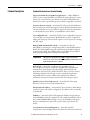
Features
The ArmorStart LT provides many features and benefits that are unsurpassed in
the market place:
• Robust IP66, UL Type 4/12 enclosure
• UL Listed, Suitable for Group Motor Applications
• UL Listed, At-motor disconnect switch
• Native support for EtherNet/IP
• Embedded dual port ethernet switch
• Device Level Ring (DLR) with Beacon frame performance
• IEEE 1588 Transparent Clock
• RSLogix 5000 Add-On Profile
• 6 user configurable I/O points
• DeviceLogix
• Embedded web server support
• Configurable e-mail response for fault or alarm events
• Optional internal power supply
• Optional electromechanical brake contactor
• Optional local control via Hand-Off-Auto keypad
• Optional quick disconnect for power and motor connections
IMPORTANT
18
Not all options are available for Bulletin 290E/291E/294E. Refer to the catalog
configurator for details.
Rockwell Automation Publication 290E-UM001B-EN-P - June 2012
Product Overview
Feature Description
Chapter 1
Standard Features Across Product Family
UL Listed “Suitable for Group Motor Applications” — Where NFPA 70
(NEC) or 79 are required installation standards, this Listing allows two or more
motors to be connected to the same branch circuit without individual motor
branch short circuit or ground fault protection. Refer to Appendix A for details.
At-motor disconnect switch — ArmorStart LT offers a local ON/OFF motor
disconnecting means with lockout-tagout provision. Industrial standards require
a local at-motor disconnect to be within eye sight of the motor for maintenance
or other shutdown reasons. Refer to your installation code for details.
User configurable I/O — ArmorStart LT offers 6 user configurable I/O points
to be used with sensors and actuators. By default all 6 points are configured as
sinking 24V DC inputs. The user has the option to select any point as a sourcing
24V DC output.
RSLogix 5000 Add-On Profile (AOP) — ArmorStart LT offers for
Allen-Bradley ControlLogix or CompactLogix PLCs a downloadable Add-On
Profile. The AOP simplifies setup and commissioning via predefined tags and
commissioning wizards. The AOP also allows copy and paste functionality for
quick setup and configuration of multiple ArmorStart LTs.
IMPORTANT
AOP support for EtherNet/IP network only and requires RSLogix 5000
revision 17.01 or later. There is a known compatibility issue with revision 20.0.
Update RSLogix 5000 to 20.1 or greater.
DeviceLogix — ArmorStart LT offers local programmable logic via
DeviceLogix. DeviceLogix is a stand-alone program that resides within the
ArmorStart LT. It is programmed locally using the Add-On-Profile and
implements operations such as, AND, OR, NOT, Timers, Counters, Latches,
and Analog operations. DeviceLogix can run as a stand-alone application,
independent of the network or collaboratively with the PLC. However,
unswitched control power must be maintained for DeviceLogix to operate.
Quick disconnect for I/O and network — ArmorStart LT offers quick
disconnect connectors for I/O and communications.
EtherNet/IP node address — ArmorStart LT offers external accessible address
switches for device node address configuration. The address can be set statically
or dynamically.
EMI filter — ArmorStart LT for VFD application (Bulletin 294) provides an
internal EMI filter and is CE compliant. For CE compliant installations refer to
the recommended EMI/RFI cord grip accessory. For availability of the quick
disconnect shielded motor cable contact your local sales representative for
details.
Local and remote status and diagnostics — ArmorStart LT offers
comprehensive status and diagnostics for I/O, Network, and device health via 12
Rockwell Automation Publication 290E-UM001B-EN-P - June 2012
19
Chapter 1
Product Overview
LEDs found on the electronic control module (ECM). If a fault occurs a local
fault reset button allows the user to quickly get the process started after corrective
action is taken. The user can also configure the embedded webserver to send an email when a fault or warning occurs.
Gland plate entrance — ArmorStart LT offers different methods of connecting
three-phase, control power, and motor. ArmorStart LT has conduit entrance
openings, as standard.
Network Options
Native EtherNet/IP — ArmorStart LT supports native EtherNet/IP without
additional modules or adapters. EtherNet/IP allows complete integration of
control with information across multiple Common Industrial Protocol (CIP™)
networks. EtherNet/IP allows users to integrate I/O control, device
configuration, and data collection across multiple networks enabling internet
connectivity and information.
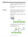
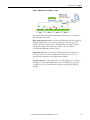
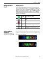
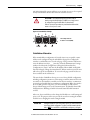
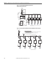
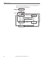
Embedded dual port switch — ArmorStart LT EtherNet/IP version includes a
dual port 10/100 mb/s ethernet switch that supports linear or Device Level Ring
(DLR) topology.
Figure 1 - Linear Topology
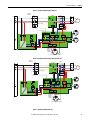
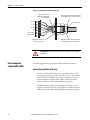
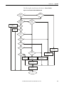
Device Level Ring (DLR) - ArmorStart LT EtherNet/IP version offers DLR
support with beacon frame performance. DLR provides a single fault tolerant
network solution for EtherNet/IP.
Figure 2 - DLR with Beacon Performance — No Fault
20
Rockwell Automation Publication 290E-UM001B-EN-P - June 2012
Product Overview
Chapter 1
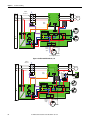
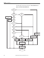
Figure 3 - DLR with Beacon Performance — Fault
In this example the fault is precisely identified by the link status message and the supervisor opens the blocked port to
allow network traffic to continue normally.
IEEE 1588 transparent clock —ArmorStart LT EtherNet/IP version supports
the IEEE 1588 transparent clock when used with precision time protocols
(PTP). A transparent clock measures and adjusts for packet delays, therefore
removing the negative effects that these variations can cause within a
synchronized distributed network of devices.
Embedded web server — ArmorStart LT EtherNet/IP version offers a web
server that can be accessed via a standard internet browser. The web server
provides status, diagnostics, and configuration capabilities.
E-mail notification — ArmorStart LT via the embedded web server, supports
configuration of the Simple Mail Transfer Protocol (SMTP). Once properly
configured, the motor controller will e-mail the user with specific fault/trip
messages.
Rockwell Automation Publication 290E-UM001B-EN-P - June 2012
21
Chapter 1
Product Overview
Factory-Installed Options
Internal power supply (IPS) — ArmorStart LT offers the user an optional
24V DC internal power supply. The internal power supply provides all control
and I/O power needs and is sourced from the incoming 3-phase power. This
eliminates the need to run separate control power to each unit, reducing
installation time and cost. The local at-motor disconnect will remove power
from the motor terminals and outputs when in the OFF condition.
Hand/Off/Auto (HOA) keypad — ArmorStart LT offers an optional local
Hand-Off-Auto keypad. This key pad allows local start/stop motor control
regardless of PLC status. This option can be used for troubleshooting or
maintenance operations. The HOA can also be disabled when local control
is not allowed, using parameter 67.
Source brake — ArmorStart LT provides an optional, internally-controlled
electromechanical motor brake contactor. The motor brake power is sourced
from 3-phase power, L1 and L2.
Quick disconnect gland — ArmorStart LT offers a plug -n- play solution that
simplifies wiring and installation. These factory installed quick disconnect
receptacles provide connectivity to ArmorConnect® media for three-phase,
control, and motor connections. The cables are ordered separately.
22
Rockwell Automation Publication 290E-UM001B-EN-P - June 2012
Product Overview
Chapter 1
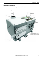
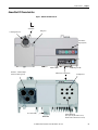
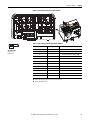
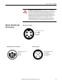
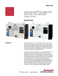
ArmorStart LT Characteristics
Figure 4 - Bulletin 290E/291E ArmorStart LT
0
Off
1
On
HOA Keypad (optional)
IP Address Switches
On/Off Switch
Status and Diagnostic LEDs
LockOut/TagOut Provision
Reset
ECM (Electronic
Control Module)
6 Configurable I/Os
Wiring Access
Dual Port EtherNet/IP
(This is replaced by a DeviceNet connector,
when DeviceNet communication is selected)
Protective Earth (PE)
Gland Plate – Conduit/Cord Grip or
ArmorConnect® Media (optional)
Rockwell Automation Publication 290E-UM001B-EN-P - June 2012
23
Chapter 1
Product Overview
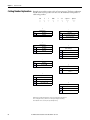
Catalog Number Explanation
Examples given in this section are for reference purposes. This basic explanation
should not be used for product selection; not all combinations will produce a
valid catalog number.
290
—
E - F
—
—
a
b
c
A
—
d
Z - G1 - Option 1 - Option 2
—
—
——
——
e
f
g
h
a
e
Bulletin Number
Control Voltage
Code
Description
Code
Description
290
Full-Voltage Starter
Z
External 24V DC control power
291
Reversing Starter
P
Internal power supply
b
f
Communications
Gland Plate Options
(Power and Motor)
Code
Description
E
EtherNet/IP
Code
Description
DeviceNet
G1
Conduit entry
G2
ArmorConnect
G3
Gland Kits ➋
D
c
Enclosure Type
Code
F
Description
g
UL Type 4/12 ➊
Option 1
Code
Description
3
Hand/Off/Auto selector keypad
3FR
Hand/Off/Auto selector keypad with
Forward/Reverse
d
Overload Selection
Code
Description
A
0.25…3.5 A
B
1.1…7.6 A
h
Option 2
Code
Description
blank
➌
No option
➊ IP66/UL Type 4 is available with all gland options. UL Type 4/12 is available with G1 and G3 gland option.
➋ See selection guide 290-SG001_-EN-P Accessories section for gland configurations and ordering.
➌ Leave blank unless there is a customer-specific option defined by the factory.
24
Rockwell Automation Publication 290E-UM001B-EN-P - June 2012
Product Overview
Chapter 1
ArmorStart LT Characteristics
Figure 5 - Bulletin 294E ArmorStart LT
0
Off
1
On
On/Off Switch
Wiring Access
LockOut/TagOut Provision
Hand-Off-Auto
Keypad (optional)
Reset
IP Address Switches
Gland Plate – Conduit/Cord Grip or
ArmorConnect Media (optional)
Status and Diagnostic LEDs
ECM (Electronic Control Module)
Protective Earth (PE)
Bottom View
Rockwell Automation Publication 290E-UM001B-EN-P - June 2012
6 Configurable I/Os
Dual Port EtherNet/IP
(This is replaced by a DeviceNet connector,
when DeviceNet communication is selected)
25
Chapter 1
Product Overview
Catalog Number Explanation
Examples given in this section are for reference purposes. This basic explanation
should not be used for product selection; not all combinations will produce a
valid catalog number.
294
—
E - F
—
—
a
b
c
D1P5
—
d
Z - G1 - Option 1 - Option 2
—
—
——
——
e
f
g
h
a
e
Bulletin Number
Control Voltage
Code
Description
Code
Description
294
VFD Starter
Z
External 24V DC control power
P
Internal power supply
b
Communications
Code
Description
E
EtherNet/IP
D
DeviceNet
f
Gland Plate Options
(Power and Motor)
Code
Description
G1
Conduit entry
G2
ArmorConnect
G3
Gland kits ➋
c
Enclosure Type
Code
Description
F
UL Type 4/12 ➊
g
Option 1
Code
Description
3
Hand/Off/Auto selector keypad with Jog
function
d
Output Current
Code
Description
D1P5
1.5 A (0.4 kW), 0.5 Hp
D2P5
2.5 A (0.75 kW), 1.0Hp
D4P2
3.6 A (1.5 kW), 2.0Hp
h
Option 2
Code
Description
SB
Source Brake
blank
➌
No option
➊ IP66/UL Type 4 is available with all gland options. UL Type 4/12 is available with G1 and G3 gland option.
➋ See selection guide 290-SG001_-EN-P Accessories section for gland configurations and ordering.
➌ Leave blank unless there is a customer-specific option defined by the factory.
26
Rockwell Automation Publication 290E-UM001B-EN-P - June 2012
Product Overview
Group Motor Installations for USA and Canada Markets
The ArmorStart LT Distributed Motor controllers are listed for use with each
other in group installations per NFPA 79, Electrical Standard for Industrial
Machinery and NFPA 70, the National Electrical Code. When applied according
to the group motor installation requirements, two or more motors are permitted
on a single branch circuit. Group Motor Installation has been successfully used
for many years in the USA and Canada.
Note: For additional information regarding group motor installations with the
ArmorStart LT Distributed Motor Controller, see Appendix A.
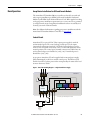
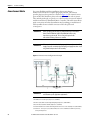
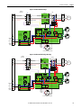
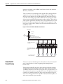
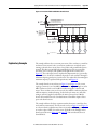
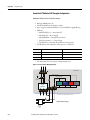
Control Circuit
ArmorStart LT accepts a 24V DC Class 2 input power supply for switched
and unswitched power. The control voltage provides power to the inputs
(unswitched) and outputs (switched). Unswitched control voltage is used to
ensure no loss of network connectivity, sensor, or other field input status under
normal operation. The control power terminal connections are labeled A1, A2,
and A3. Switched power is identified as (+A1) (-A2). Unswitched power is
identified as (+A3) (-A2).
As an option, ArmorStart LT can be supplied with an internal power supply
(IPS) eliminating the need for an external control power. The IPS is sourced
from the line side of 3-phase power and is not impacted by the status of the local
at-motor disconnect switch.
Figure 6 - Control Circuit Wiring Diagram — Single External Power Supply
ArmorStart LT
L1
L2
L3
Switched Control Power
Off
Unswitched Control Power
*
Basic Operation
Chapter 1
Disconnect
EtherNet
Comms
Inputs
Outputs
Motor
Control
Motor
Controller
A1
T1
T2
A2
A3
T3
* Control power output is determined by disconnect status
L
+
24VDC
-
N
Class 2
External
24VDC Power
Supply
Rockwell Automation Publication 290E-UM001B-EN-P - June 2012
27
Chapter 1
Product Overview
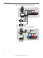
Figure 7 - Control Circuit Wiring Diagram — Multiple External Power Supplies
ArmorStart LT
L1
L2
L3
Switched Control Power
Off
*
Unswitched Control Power
Disconnect
EtherNet
Comms
Inputs
Motor
Control
Outputs
Motor
Controller
A1
T1
T2
A2
A3
T3
* Control power output is determined by disconnect status
Class 2
External Switched
24VDC Power Supply
Class 2
External Unswitched
24VDC Power Supply
L
+
24VDC
-
N
L
+
24VDC
-
N
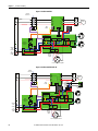
Figure 8 - Control Circuit Wiring Diagram — Internal Power Supply (optional)
ArmorStart LT
L1
L2
Internal Power
Supply
L3
Off
Disconnect
T2
Inputs
*
T1
EtherNet
Comms
*
Motor
Controller
Outputs
Motor
Control
T3
* Control power output is determined by disconnect status
28
Rockwell Automation Publication 290E-UM001B-EN-P - June 2012
Product Overview
Chapter 1
Motor Circuit
The ArmorStart LT Distributed Motor Controllers are rated to operate the
following types of three-phase squirrel-cage induction motors:
Bulletin 290E/291E:
0.5 Hp (0.37 kW) to 5 Hp (3 kW) @ 480/277V AC
Bulletin 294E:
0.5 Hp (0.37 kW) to 2 Hp (1.5 kW) @ 480/277V AC
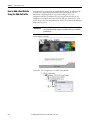
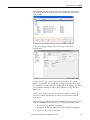
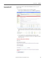
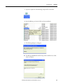
Local I/O
The ArmorStart LT provides as standard, 6 user configurable I/O points. By
default, all points are configured as an Input. When not using the AOP, the
user will need to refer to parameter 49 [IOPointConfiguration], to define an
output point.
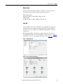
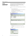
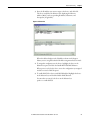
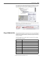
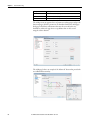
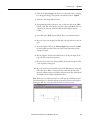
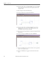
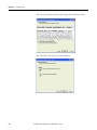
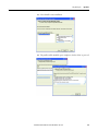
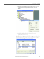
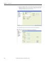
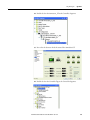
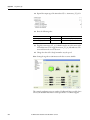
When using the AOP, the I/O point is configured from the General screen
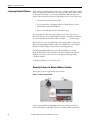
in the Module Definition section by clicking the “Change” button, see Figure 9.
This allows user to view and configure the I/O mix, refer to Figure 10.
Figure 9 - Defining I/O Point
Figure 10 - Current I/O Point Configuration
Rockwell Automation Publication 290E-UM001B-EN-P - June 2012
29
Chapter 1
Product Overview
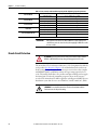
Overload Protection
The ArmorStart LT Distributed Motor Controller incorporates, as standard,
electronic motor overload protection. This overload protection is accomplished
electronically with an I2t algorithm. The ArmorStart LT’s overload protection is
programmable via the communication network, providing the user with greater
flexibility.
The Bulletin 290E/291E includes programmable overload Class 10, 15, and 20
protection. The Bulletin 294E provides overload protection: 150% for 60s and
200% for 3s.
Refer to Chapter 6, Specifications, for additional information.
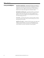
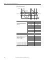
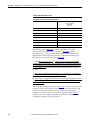
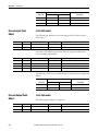
Mode of Operation
Bulletin 290E/291E
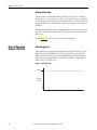
Full-Voltage Start
This method is used in applications requiring across-the-line starting, in which
full inrush current and locked-rotor torque are realized. The ArmorStart LT
Bulletin 290E offers full-voltage starting and Bulletin 291E offers full-voltage
starting for reversing applications, from 0.5 Hp (0.37 kW) to 5 Hp (3 kW) at
480Y/277V AC, 3-phase power.
Figure 11 - Full-Voltage Start
100%
Percent
Voltage
Time (seconds)
30
Rockwell Automation Publication 290E-UM001B-EN-P - June 2012
Product Overview
Mode of Operation
Bulletin 294E
Chapter 1
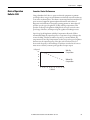
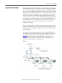
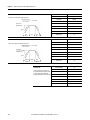
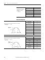
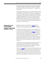
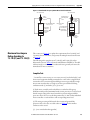
Sensorless Vector Performance
Using a distributed AC drive to operate mechanical equipment at optimum
speed helps reduce energy costs and eliminates mechanical wear and tear that can
occur in the mechanical parts. The advance monitoring found in ArmorStart LT
protects critical equipment against unplanned downtime with advanced
diagnostics and notification of irregular operating parameters. ArmorStart LT
provides open-loop speed regulation (V/Hz) with slip compensation. This
provides excellent speed regulation and high levels of torque across the entire
speed range of the drive, and improved speed regulation as loading increases.
Open Loop Speed Regulation with Slip Compensation allows the VFD to
automatically adjust the output frequency to compensate for speed changes due
to motor loading. This feature utilizes an open loop, current feedback, slip
compensation circuit. Slip Compensation works as an open loop speed regulator
that increases the output frequency of the drive as the load is increased, or
decreases the frequency as the load drops. This feature is used where the motor
must run at a relatively constant speed regardless of torque output.
% of speed
With Slip
Compensation
100
99
98
Without Slip
Compensation
97
96
95
0
10 20 30 40 50 60 70 80 90 100
% of load
Rockwell Automation Publication 290E-UM001B-EN-P - June 2012
31
Chapter 1
Product Overview
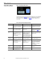
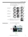
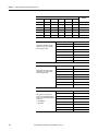
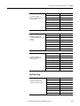
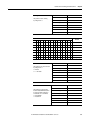
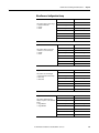
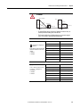
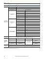
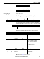
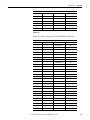
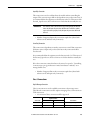
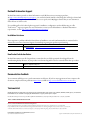
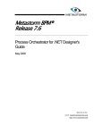
Status LEDs and Reset
Figure 12 - Status, Diagnostic LEDs, and Reset
ArmorStart LT provides comprehensive status and diagnostics via 12 individually
marked LEDs shown in Figure 12, located on the ECM module. In addition, a
local reset is provide for clearing of faults. Table 5 details the diagnostic and
status LEDs.
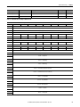
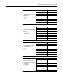
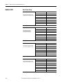
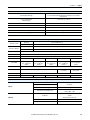
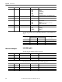
Table 5 - ArmorStart LT Status and Diagnostics Indicators
32
Indicator
Description
Color_1
Color_2
PWR LED
The bicolor (green/yellow) LED shows the
state of the control voltage. When LED is
off, switched and/or unswitched power is
not present.
Solid green is illuminated when switched Solid yellow is illuminated when switched
and unswitched control power is within its or unswitched control power is outside its
specified limits and has the proper polarity. specified limits or has incorrect polarity.
RUN/FLT LED
The bicolor (green/red) LED combines the
functions of the Run and Fault LEDs.
Solid green is illuminated when a Run
command is present.
The LED will blink red in a prescribed fault
pattern when a protection fault (trip)
condition is present. See Table 6 for fault
blink patterns.
NS – Network Status
LED
The bicolor (green/red) LED indicates the
status of the CIP network connection. See
Network Status Indicator for further
information.
Flashing bicolor (red/green) indicates a
self-test on power up.
Flashing green indicates an IP address is
configured, no CIP connections are
established, and an Exclusive Owner
connection has not timed out.
Steady green indicates at least one CIP
connection is established and an Exclusive
Owner connection has not timed out.
Flashing red indicates the connection has
timed out. Steady Red indicates a duplicate
IP Address detected.
LS1 and LS2 – Link
Status LEDs
The bicolor (green/yellow) LED shows the
activity/link status of each EtherNet/IP
port.
Solid green is illuminated when a link has
been established at 100 Mbps.
Solid yellow is illuminated when a link has
been established at 10 Mbps.
MS – Module Status
LED
The bicolor (green/red) LED indicates the
status of the module.
Flashing bicolor (red/green) indicates a
self-test on power up.
Flashing green indicates the device has not
been configured.
Steady green indicates the device is
configured and operational.
Flashing red indicates a resettable
protection fault exists or the node address
switches have been changed without a
power cycle and do not match the in-use
configuration.
Steady red indicates a non-resettable
protection fault exists.
I/O Status
Enunciators 0…5
LEDs
Six yellow LEDs are numbered 0…5 and
indicate the status of the input/output
connectors. One LED for each I/O point.
Yellow is illuminated when input is valid or
output is on.
Off when input is not valid or the output is
not turned on.
Reset Button
The blue reset button will cause a
protection fault reset to occur.
—
—
Rockwell Automation Publication 290E-UM001B-EN-P - June 2012
Product Overview
Chapter 1
Electronic Data Sheet (EDS)
ArmorStart LT EtherNet/IP has an embedded electronic data sheet. An EDS
consists of specially formatted text files, as defined by the CIP™. EDS files contain
details about the readable and configurable parameters of the EtherNet/IP
device. They also provide information about the I/O connections that the device
supports and the content of the associated data structures. EDS are used by
EtherNet/IP device configuration tools, such as RSNetWorx™ for EtherNet/IP,
and data servers such as RSLinx® Classic.
EDS files for all ArmorStart LT EtherNet/IP devices can be uploaded directly
from the device via the web server interface. Rockwell Automation product EDS
files are also available on the internet at: http://www.ab.com/networks/eds.
Rockwell Automation Publication 290E-UM001B-EN-P - June 2012
33
Chapter 1
Product Overview
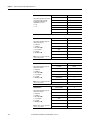
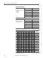
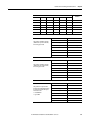
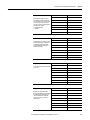
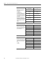
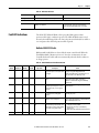
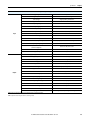
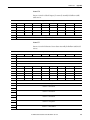
Fault Diagnostics
Fault diagnostics capabilities built in the ArmorStart LT Distributed Motor
Controller are designed to help you pinpoint a problem for easy troubleshooting
and quick re-starting.
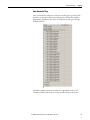
Protection Faults
Protection faults will be generated when potentially dangerous or damaging
conditions are detected. Protection faults are also known as “trips” or “faults”.
These faults will be reported in multiple formats, including:
• Bit enumeration in the TripStatus parameter 16 in DeviceLogix
• In the ArmorStart LT web server for ArmorStart EtherNet/IP version
• As a sequence of LED flashes on the ECM
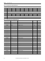
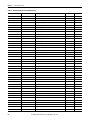
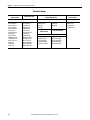
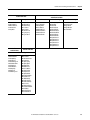
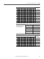
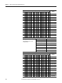
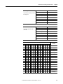
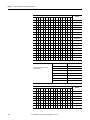
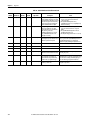
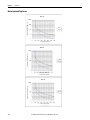
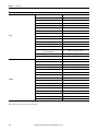
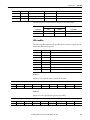
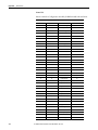
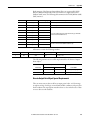
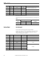
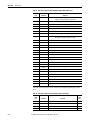
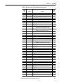
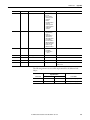
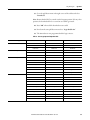
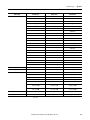
Table 6 - Protection Faults
LED Flash
Bit Enumeration
Bulletin 290E/291E Trip Status Bits
Bulletin 294E Trip Status Bits
1
0
OverloadTrip ➊
OverloadTrip ➊
2
1
PhaseLossTrip
PhaseLShortTrip
3
2
UnderPowerTrip ➊
UnderPowerTrip ➊
4
3
SensorShortTrip ➊
SensorShortTrip ➊
5
4
PhaseImbalTrip
OverCurrentTrip
6
5
NonVolMemoryTrip ➊
NonVolMemoryTrip ➊
7
6
reserved
ParamSyncTrip ➊
8
7
JamTrip
DCBusOrDiscnnct ➊
9
8
StallTrip
StallTrip ➊
10
9
UnderloadTrip
OverTemperature ➊
11
10
reserved
GroundFault ➊
12
11
reserved
RestartRetries
13
12
reserved
DriveHdwFault ➊
14
13
OutputShortTrip ➊
OutputShortTrip ➊
15
14
UserDefinedTrip
UserDefinedTrip
16
15
HardwareFltTrip ➊
HardwareFltTrip ➊
➊ Cannot be disabled.
34
Rockwell Automation Publication 290E-UM001B-EN-P - June 2012
Product Overview
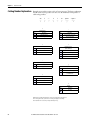
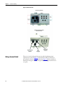
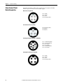
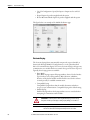
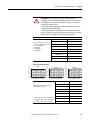
Optional HOA Selector
Keypad
Optional HOA Keypad
Configuration
(Bulletin 290E/291E only)
Chapter 1
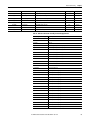
Keypad Local Control
The HOA Selector Keypad allows for local start/stop/jog control in forward/
reverse motor direction. If two buttons are pressed simultaneously, this action is
ignored by the device unless one of the buttons is the OFF button. If the OFF
button is pressed at any time, the unit will go to the off state. When local Hand
mode is entered, speed reference is switched to Internal Frequency. When in
“Auto” mode the unit the speed reference is switched to the mode specified in
parameter 33 “SpeedReference”.
HAND
The Hand key will initiate starter operation
AUTO
The Auto key allows for Start/Stop control via the communications
network
OFF
If the starter is running, pressing the OFF key will cause the starter to stop.
DIR Arrow
The Dir arrow selects the direction of the motor, either forward or reverse.
JOG
When pressed, JOG will be initiated if no other control devices are sending
a stop command. Releasing the key will cause the drive to stop, using
selected stop mode.
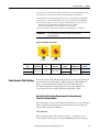
The ArmorStart LT offers optional factory-installed Hand/OFF/Auto (HOA)
configurations: Standard (Bulletin 290E) and Forward/Reverse (Bulletin 291E).
Figure 13 - Bulletin 290E Standard HOA
Figure 14 - Bulletin 291 Forward/Reverse HOA
E
Rockwell Automation Publication 290E-UM001B-EN-P - June 2012
35
Chapter 1
Product Overview
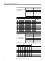
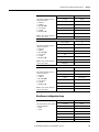
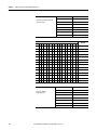
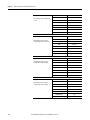
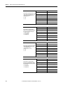
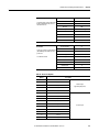
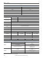
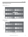
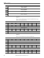
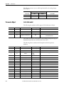
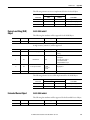
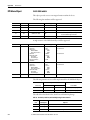
Bulletin 290E
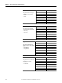
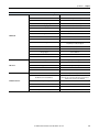
With the KeypadMode parameter (parameter 66) set to 1 = Maintained, pressing
the buttons reacts like a maintained switch.
Current Mode
Key Press
OFF
HAND
AUTO
AUTO
Auto Mode — Motor Off
—
—
HAND
If no fault, Motor On
—
—
OFF
—
Motor turns Off
Motor turns Off
FAULT PRESENT
—
Motor turns Off
Motor turns Off
With the KeypadMode parameter (parameter 66) set to 0 = Momentary,
pressing the buttons reacts like a momentary switch.
Current Mode
Key Press
OFF Key
HAND
AUTO Key
—
Motor Off
—
AUTO
Auto Mode — Motor Off
—
—
HAND
If no fault, Motor On
—
—
OFF
—
Motor Off
Motor Off
PROTECTION FAULT PRESENT
—
Motor Off
—
NO KEY PRESSED
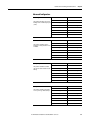
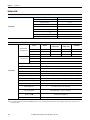
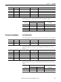
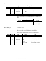
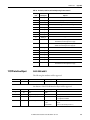
Bulletin 291E
With the KeypadMode parameter (parameter 66) set to 1 = Maintained, pressing
the buttons reacts like a maintained switch.
Current Mode
Key Press
FWD/REV
OFF
HAND
AUTO
FWD LED Set REV LED
REV LED Set FWD LED
—
—
AUTO
Auto Mode — Motor Off
—
—
HAND
If no fault, Motor On
—
—
OFF
Ignore
Motor Off
Motor Off
PROTECTION FAULT PRESENT
Ignore
Motor Off
—
With the KeypadMode parameter (parameter 66) set to 0 = Momentary,
pressing the buttons reacts like a momentary switch.
Current Mode
Key Press
OFF
HAND
AUTO
—
Motor Off
—
FWD LED Set REV LED
REV LED Set FWD LED
—
—
AUTO
Auto Mode — Motor Off
—
—
HAND
NO KEY PRESSED
FWD/REV
36
If no fault, Motor On
—
—
OFF
—
Motor Off
Motor Off
PROTECTION FAULT PRESENT
—
Motor Off
—
Rockwell Automation Publication 290E-UM001B-EN-P - June 2012
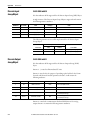
Product Overview
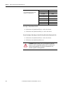
Optional HOA Selector
Keypad with Jog Function
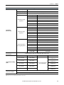
(Bulletin 294E only)
Chapter 1
The HOA Selector Keypad with Jog function allows for local start/stop control
with capabilities to jog in forward/reverse motor directions.
Figure 15 - Bulletin 294E Jog/Forward/Reverse HOA
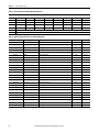
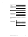
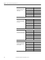
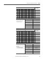
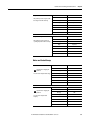
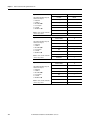
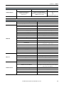
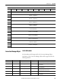
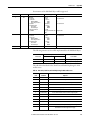
Keypad Local Control
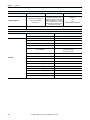
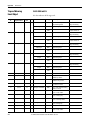
With the KeypadMode parameter (parameter 66) set to 1 = Maintained, pressing
the buttons reacts like a maintained switch.
Current Mode
Key Press
OFF
HAND
JOG
AUTO
—
—
Motor Off
—
FWD/REV
FWD LED Set REV LED
REV LED Set FWD LED
FWD LED Set REV LED
REV LED Set FWD LED
—
—
JOG
If no fault, Jog Motor
—
—
—
AUTO
Auto Mode — Motor Off
—
—
—
HAND
If no fault, Motor On
—
—
—
OFF
—
Motor Off
Motor Off
Motor Off
PROTECTION FAULT PRESENT
—
Motor Off
Motor Off
—
NO KEY PRESSED
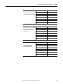
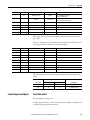
With the KeypadMode parameter (parameter 66) set to 0 = Momentary,
pressing the buttons reacts like a momentary switch.
Current Mode
Key Press
OFF
HAND
JOG
AUTO
—
Motor Off
Motor Off
—
FWD/REV
FWD LED Set REV LED
REV LED Set FWD LED
FWD LED Set REV LED
REV LED Set FWD LED
—
—
JOG
If no fault, Jog Motor
—
—
—
AUTO
Auto Mode — Motor Off
—
—
—
HAND
If no fault, Motor On
—
—
—
OFF
—
Motor Off
Motor Off
Motor Off
PROTECTION FAULT PRESENT
—
Motor Off
Motor Off
—
NO KEY PRESSED
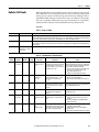
IMPORTANT
If multiple buttons are pressed at the same time, the software interprets this as
a “no button pressed” condition. The only exception to this rule is if multiple
buttons are pressed and one of them is the OFF button. If the OFF button is
pressed in combination with any combination of other buttons, the processor
will behave as if the OFF button were pressed by itself.
Rockwell Automation Publication 290E-UM001B-EN-P - June 2012
37
Chapter 1
Product Overview
Keypad Disable Parameter
“Keypad Disable”, parameter 67, only inhibits the “HAND”, “FWD”, “REV” and
“JOG” buttons on the HOA keypad. The “OFF” and “AUTO” buttons are
always enabled, even if parameter 67 is set to “1=Disable”. The keypad OFF
button can not be disabled.
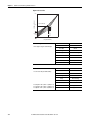
Source Brake Contactor
and Connector
(Bulletin 294E only)
An internal contactor is used to switch the electromechanical motor brake
On/Off. The motor brake contactor is actuated via the internal power which
supplies L1 and L2 voltage to the mechanical brake in the motor. The source
brake can be configured for independent control via parameter configuration.
The internal contactor, electromechanical motor brake, and associated motor
branch cable are protected by the branch circuit protective device. There is no
resettable or replaceable protective device in ArmorStart LT.
WARNING: If the branch circuit protective device trips, the user must ensure
that the Source Brake function is still operational prior to putting the
equipment back in service. If the source brake function is not working properly,
loss of brake function or motor damage can occur.
38
Rockwell Automation Publication 290E-UM001B-EN-P - June 2012
Chapter
2
Installation and Wiring
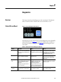
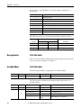
Receiving
It is the responsibility of the user to thoroughly inspect the equipment before
accepting the shipment from the freight company. Check the item(s) received
against the purchase order. If any items are damaged, it is the responsibility of the
user not to accept delivery until the freight agent has noted the damage on the
freight bill. Should any concealed damage be found during unpacking, it is also
the responsibility of the user to notify the freight agent. The shipping container
must be left intact and the freight agent should be requested to make a visual
inspection of the equipment.
Unpacking
Remove all packing material, wedges, or braces from within and around the
ArmorStart LT distributed motor controller and other device(s). Check the
contents of the package to see if all contents are included. Contact your local
Allen-Bradley representative if any items are missing.
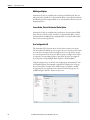
IMPORTANT
Before the installation and start-up of the drive, a general inspection
of mechanical integrity (i.e. loose parts, wires, connections, packing
materials, etc.) must be made.
Inspecting
After unpacking, check nameplate catalog number(s) of the item(s) against the
purchase order. See Chapter 1 for an explanation of the catalog numbering system
which will aid in nameplate interpretation.
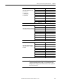
Storing
The controller should remain in the shipping container prior to installation.
If the equipment is not to be used for a period of time, it must be stored according
to the following instructions in order to maintain warranty coverage.
• Store in a clean, dry location.
• Store within an ambient temperature range of –25…+85°C
(–13…+185°F).
• Store within a relative humidity range of 0…95%, noncondensing.
• Do not store equipment where it could be exposed to a corrosive
atmosphere.
• Do not store equipment in a construction area.
Rockwell Automation Publication 290E-UM001B-EN-P - June 2012
39
Chapter 2
Installation and Wiring
Installation Precautions
The following statements must be read and understood.
ATTENTION: The earth ground terminal shall be connected to a solid earth
ground via a low-impedance connection.
ATTENTION: Copper ground conductors are recommended. The ArmorStart LT
external protective earth (PE) pad is aluminum. Refer to your local electrical
installation standard for proper bonding and protection when dissimilar metals
are used.
ATTENTION: An incorrectly applied or installed controller can damage
components or reduce product life. Wiring or application errors, such as
undersizing the motor, incorrect or inadequate AC supply, or out of range
ambient temperatures, may result in malfunction of the system.
Precautions for
Bulletin 290E/291E
Applications
Precautions for
Bulletin 294E Applications
Dimensions
40
SHOCK HAZARD: To prevent electrical shock, open appropriate machine
disconnect switch prior to connecting and disconnecting cables. Risk of shock —
environment rating may not be maintained with open receptacles.
SHOCK HAZARD: The drive contains high voltage capacitors which take time
to discharge after removal of mains supply. Before working on drive, ensure
isolation of mains supply from line inputs (L1, L2, L3). Wait three minutes
for capacitors to discharge to safe voltage levels. Failure to do so may result
in personal injury or death.
ArmorStart LT consists of three components that are non-replaceable. The
Electronic Control Module (ECM); a gland plate for wire entry; and the
aluminum alloy enclosure which makes up the back cover, top housing, and
wiring access door. The ECM includes communications, discrete I/O, status and
diagnostic LEDs, and the node address switches. All mating surfaces are sealed
using foam in place gasket or o-ring.
Rockwell Automation Publication 290E-UM001B-EN-P - June 2012
Installation and Wiring
Chapter 2
Dimensions are shown in millimeters (inches). Dimensions are not intended
to be used for manufacturing purposes. All dimensions are subject to change.
Dimensions
Figure 16 - Dimensions for Bulletin 290E/291E
130
(5.1)
260
(10.2)
166,5
(6.6)
217,83
(8.6)
202,05
(8.0)
170
(6.7)
152,65
(6.0)
65
(2.6) Front View
Right Side View
Line
Control
Motor
37
(1.5)
37
(1.5)
57,13
(2.3)
57,13
(2.3)
38.49
(1.5)
38,49
(1.5)
1 in. conduit opening
24,25 48,5
(1.0) (1.9)
ArmorConnect Media
Gland Entrance (optional)
24,25
(1.0) 48,5
Conduit Gland Entrance
(1.9)
0.75 in. conduit opening
Line
Motor
Line
Motor
Control
37
(1.5)
37
(1.5)
Source Brake
57,13
(2.3)
57,13
(2.3)
38,61
(1.5)
24,25
(1.0)
ArmorConnect Internal Power
Supply Gland Plate (optional)
IMPORTANT
38,49
(1.5)
48,5
(1.9)
ArmorConnect Source Brake
Gland Plate (optional)
For proper heat dissipation and product operation, mount the ArmorStart LT in the
vertical orientation as shown.
Rockwell Automation Publication 290E-UM001B-EN-P - June 2012
41
Chapter 2
Installation and Wiring
Figure 17 - Dimensions for Bulletin 294E
381
(15.0)
240
(9.4)
219,32
(8.6)
206,43
(8.1)
170
(6.7)
120
(4.7)
Front View
202,27
(8.0)
37
(1.5)
92,9
(3.7)
38.49
(1.5)
24,25
(1.0)
1 in. conduit opening
48,5 0.75 in. conduit opening
(1.9)
Right Side View
Conduit Gland Entrance - Bottom View
Line
Motor
Motor
37
(1.5)
92,9
(3.7)
24,25
(1.0)
Line
Motor
Control
37
(1.5)
37
(1.5)
92.9
(3.7)
38,61
(1.5)
Control
Line
Source Brake
92,9
(3.7)
38,55
(1.5)
24,25
(1.0)
48,5
(1.9)
38,55
(1.5)
48,5
(1.9)
ArmorConnect Internal Power ArmorConnect Media Gland ArmorConnect Gland Entrance
with Source Brake (optional)
Supply Gland Plate (optional)
Entrance (optional)
IMPORTANT
42
For proper heat dissipation and product operation, mount the ArmorStart LT in the
vertical orientation as shown.
Rockwell Automation Publication 290E-UM001B-EN-P - June 2012
Installation and Wiring
Chapter 2
Dimensions are shown in millimeters (inches). Dimensions are not intended
to be used for manufacturing purposes. All dimensions are subject to change.
Figure 18 - ArmorStart LT Gland Plate Matrix
G1 Conduit
Standard
U.S. Trade Knock-outs
G3 Conduit
Daisy Chaining
IP66 Metric Fittings
G2 Media
Dia. 25.5 mm
Dia. 20.5 mm
No Internal Power Supply
No Source Brake
Source Brake
No Internal Power Supply
Cat. No.
290-G3-A2
1.00 in.
(25.4 mm)
0.75 in.
(19.05 mm)
0.75 in.
(19.05 mm)
Dia. 25.5 mm
Dia. 20.5 mm
290-G3-A3
Dia. 25.5 mm
Internal Power Supply
No Source Brake
1.00 in.
(25.4 mm)
0.75 in.
(19.05 mm)
Internal Power Supply
and Source Brake
1.00 in.
(25.4 mm)
0.75 in.
(19.05 mm)
Dia. 20.5 mm
290-G3-A4
Dia. 25.5 mm
Dia. 20.5 mm
290-G3-A5
45°
290-G3-A1
Gland Plate Clearances
User Modified
10.1 mm
Connection Locations
80.7 mm
Modifications are not permitted in the keepout region. Fitting(s) should be oriented 66.1 mm
so that they do not interfere with the enclosure when the gland plate is installed.
Torque the gland mounting screws to 12…14 in•lb (1.3…1.6 N•m).
91.3 mm
11.8 mm
Figure 19 - Internal Power, Control, and Ground Locations
Rockwell Automation Publication 290E-UM001B-EN-P - June 2012
43
Chapter 2
Installation and Wiring
Figure 20 - Gland Connection
Wiring Terminal Detail
44
The power, control, and ground wire capacity and the tightening torque
requirements are shown in Table 8. The maximum number of connections
per terminal are shown in Table 7. As shown in Figure 21 all the terminals are
found in the wiring area. Access can be gained by removing the terminal access
cover plate.
Rockwell Automation Publication 290E-UM001B-EN-P - June 2012
Installation and Wiring
Chapter 2
Figure 21 - ArmorStart LT Power and Control Terminals
A1
L1
L2
L3
T1
T2
T3
A2
A3
PE
B1
B2
Table 7 - Power, Control, and Ground Terminal Designations
Wire Strip Length
0.35 ± 0.01 in.
(9 ± 0.2 mm)
Terminal Designations
Wires/Connections
Description
A1
2
Switched 24V DC Control Power (+) ➊
A2
2
Control Power Common (–) ➊
A3
2
Unswitched 24V DC Control Power (+) ➊
PE
2
Ground
L1
2
Line Power – Phase A
L2
2
Line Power – Phase B
L3
2
Line Power – Phase C
T1
1
Motor Connection – Phase A
T2
1
Motor Connection – Phase B
T3
1
Motor Connection – Phase C
B1
1
Source Brake Connection – B1 ➋
B2
1
Source Brake Connection – B2 ➋
➊ When internal power supply option is selected, no connection is made here.
➋ Available only with Bulletin 294E.
Rockwell Automation Publication 290E-UM001B-EN-P - June 2012
45
Chapter 2
Installation and Wiring
Table 8 - Power, Control, and Ground Wire Capacity and the Tightening Torque Requirements
Wire Size
Power Terminals
Motor Terminals
Control Terminals
PE/Ground
Source Brake (Bulletin 294)
(2) #18…#10 AWG (0.8…5.2 mm2) per terminal
Tightening Torque
10.6 +/– 2 lb•in (1.2 +/– 0.2 N•m)
Wire Size
#18…#10 AWG (0.8…5.2 mm2) per terminal
Tightening Torque
10.6 +/– 2 lb•in (1.2 +/– 0.2 N•m)
Wire Size
(2) #18…#10 AWG (0.8…5.2 mm2) per terminal
Tightening Torque
10.6 +/– 2 lb•in (1.2 +/– 0.2 N•m)
Wire Size
(2) #16…#10 AWG (1.3…5.2 mm2) per terminal
Tightening Torque
18 +/– 2 lb•in (2 +/– 0.2 N•m)
Wire Size
#16 …#10 AWG (1.0…4.0 mm2) per terminal
Tightening Torque
4.8 ± 2 lb•in (0.5 ± 0.2 N•m )
IMPORTANT
ArmorStart LT is UL Listed for use with 14 AWG wire or preassemble power
cable. Refer to your local electrical code(s) when applying 16 AWG wire or cable
in a motor circuit.
Branch Circuit Protection
ATTENTION: Select the motor branch circuit protection that complies with the
NFPA79/ or NFPA70 (NEC) and any other governing regional or local codes.
The ArmorStart LT is Underwriters Laboratory (UL) Group Motor listed. Refer
to the product Specifications, Chapter 6 for maximum branch fuse and circuit
breaker ratings. Select the motor branch circuit protection device that complies
with NFPA70 (NEC) or NFPA79, and any other governing regional or local
codes. The installer shall observe the product nameplate markings and not apply
the ArmorStart LT where the maximum perspective short circuit current is
exceeded. The ArmorStart LT shall be applied to a solidly grounded WYE power
distribution system that does not exceed 480V AC, 60 Hz or 400V AC, 50 Hz.
WARNING: Do not install the ArmorStart LT where the maximum available
fault current exceeds the product rating.
46
Rockwell Automation Publication 290E-UM001B-EN-P - June 2012
Installation and Wiring
Typical System Example
Chapter 2
The primary function of ArmorStart LT is to control and protect a three-phase
squirrel cage induction motor. Three-phase power enters through terminals that
are connected to a manually operated disconnect switch. The three-phase power
may also connect internally to an optional three-phase to 24V DC power supply
(IPS). Wired in series with the disconnect is an electrically operated contactor or
a variable frequency drive. For Bulletin 294E an optional source brake contactor
may also be connected to the disconnect output terminals. The source brake
contactor is used to control an electromechanical brake physically attached to the
motor. The microcontroller and interface circuits are contained in the ECM.
The ECM also houses 6 user configurable I/O points. These six I/O points are
used for system level control and are accessible via by the communication
network or DeviceLogix.
The user has the flexibility to coordinate the appropriate safety function for their
application. ArmorStart LT does not provide a safe torque-off input. Therefore,
the safety function is configured externally from the controller and based upon
the risk assessment.
For example, the risk assessment may require a safety circuit with a high level
of performance. In this example, a safety relay with redundant safety contactors
and emergency stop function can be integrated into the machine controls.
Figure 22 below is an example of this configuration. Contact your local
Rockwell Automation supplier for additional support regarding the safety
circuit or for a risk assessment of your machinery.
Figure 22 -
Rockwell Automation Publication 290E-UM001B-EN-P - June 2012
47
Chapter 2
Installation and Wiring
ArmorConnect Media
For greater flexibility and faster installations the user may also use
ArmorConnect media for a complete plug-n-play solution. This solution
provides plug-in style stop stations, as shown in Figure 23. The ArmorConnect
power media offers both three-phase and control power cable cord set systems.
These include patchcords, receptacles, tees, reducers and accessories to be utilized
with the ArmorStart LT Distributed Motor Controller. This cable system allows
quick connections and reduced installation time by utilizing pre-manufactured
cable assemblies for more reliable connection of the three phase and
control power.
IMPORTANT
When specifying power media for use with the ArmorStart LT Distributed
Motor Controllers (Bulletin 290E/291E and Bulletin 294E) use only
ArmorConnect power media. The use of any other power media
will void the UL Listing of the motor controller.
IMPORTANT
Refer to your local electrical code for proper application and protection of long
length power cable to minimize physical damage and appropriate short-circuit
and ground-fault protection for the assembly.
Figure 23 - ArmorConnect Configuration Example
IMPORTANT
A single channel Stop is pictured. It is necessary to perform a risk assessment
and determine specific application requirements.
1. CAT5e Bulkhead Connector and Receptacle (Example Cat. No.:1585A-DD4JD)
2. CAT5e Patch Cord, IP67, M12 D-Code, Male Straight, Male Right Angle (Example Cat. No.: 1585D-M4TBDE-*)
3. CAT5e, Patch Cable, IP20, RJ45 Male to RJ45 Male (Example Cat. No. 1585J-M4TB-*)
4. Control Power Media Patchcords – PatchCord cable with integral female or male connector on each end (Example Cat. No.: 889N-F65GFNM-*)
5. Control Power Tees – The E-stop In Tee (Cat. No.: 898N-653ST-NKF) is used to connect to the Bulletin 800F On-Machine Stop station using
a control power media patchcord.
48
Rockwell Automation Publication 290E-UM001B-EN-P - June 2012
Installation and Wiring
Chapter 2
6. The E-stop Out tee (Cat. No.: 898N-653ES-NKF) is used with cordset or patchcord to connect to the ArmorStart Distributed Motor Controller.
7. Control Power Receptacles – Female receptacles are a panel mount connector with flying leads (Cat. No.: 888N-D65AF1-*)
8. Three-Phase Power Trunk – Patchcord cable with integral female or male connector on each end (Example Cat. No.:280-PWRM35A-M*)
9. Three-Phase Drop Cable – PatchCord cable with integral female or male connector on each end (Example Cat. No.:280-PWRM22A-M*)
10. Three-Phase Power Tees and Reducer – Tee connects to a single drop line to trunk with quick change connectors (Cat. No.: 280-T35)
Reducing Tee connects to a single drop line (Mini) to trunk (Quick change) connector (Cat. No.: 280-RT35)
Reducer connects from quick change male connector to mini female connector (Cat. No.: 280-RA35)
11. Three-Phase Power Receptacles – Female receptacles are a panel mount connector with flying leads (Cat. No.: 280-M35F-M1)
IMPORTANT
See the On-Machine Connectivity catalog for specific Ethernet
media components
Figure 24 - On-Machine Stop Stations
Enclosure
Type
Plastic
Metal
Quick Connect
Knockout
Type
Operator
Mini Receptacle
Metric
Twist to Release
ArmorConnect Cable Ratings
Illumination
Voltage
24V AC/DC
24V AC/DC
Contact
Configuration
1 N.C./1 N.O.
Cat. No.
800F-1YMQ4
800F-1MYMQ4
The ArmorConnect Power Media cables are rated per UL Type TC 600V 90°C
Dry 75°C Wet, Exposed Run (ER) or MTW 600V 90°C or STOOW 105°C
600V - Canadian Standards Association (CSA) STOOW 600V FT2.
For additional information regarding ArmorConnect Power Media refer
to ArmorStart LT selection guide, publication 290-SG001_-EN-P.
Branch Circuit Protection Requirements for ArmorConnect
Three-Phase Power Media
When using ArmorConnect Three-Phase Power Media, fuses or circuit breakers
may be used for the motor branch circuit ground fault protection if properly
sized and allowed by product labeling.
Circuit Breaker:
Where ArmorStart LT is used with ArmorConnect — suitable for use on a
circuit capable of delivering not more than 10000 RMS Symmetrical Amperes
Rockwell Automation Publication 290E-UM001B-EN-P - June 2012
49
Chapter 2
Installation and Wiring
at 480Y/277 VAC maximum when protected by Cat. No.140U-D6D3-C30
circuit breaker, refer to the Specifications, Chapter 6.
WARNING: The total circuit impedance including each cable assembly's own
impedance, must be low enough to ensure any short-circuit or ground fault
current that can flow through any assembly, will be large enough to operate the
magnetic trip of the Cat. No. 140U-D63-C* circuit breaker. Refer to NFPA 70 and
NFPA 79 or your local electrical code for guidance in coordinating over current
protective devices and the circuit being protected.
Fusing:
Where ArmorStart LT is used with ArmorConnect — suitable for use on a
circuit capable of delivering not more than 10000 RMS Symmetrical Amperes
(SCCR) at 480/277 V AC maximum when protected by 40 A CC, J, and T
class fuses, refer to the Specifications, Chapter 6.
Electrical Wiring
ArmorStart LT EtherNet/IP utilizes 24V DC control power for communications
and I/O. The control power terminal connections are labeled A1, A2, and A3.
Switched power (A1) will supply outputs and motor control. Unswitched
power (A3) will supply logic power, communications, and sensor inputs.
IMPORTANT
50
EtherNet/IP is an unpowered network, therefore if device status is important,
the A3 terminal must have an unswitched power source.
Rockwell Automation Publication 290E-UM001B-EN-P - June 2012
Installation and Wiring
Chapter 2
Figure 25 - Bulletin 290E Full Voltage
At Motor
Disconnect
DOL
Overload
L1
T1
L2
T2
L3
T3
Disconnect Status
Motor
Fwd Status
Fwd Control
Disconnect
State,
Voltage
Monitoring
and Power Loss
PE
Switched
(SW)
Common
UnSwitched
(USW)
Power
Conditioning
Board
A1
Internal
Outputs
Micro
Internal
Inputs
EtherNet/IP
Logic
Power
Loss
A2
External External
Outputs Inputs
A3
Sensor Voltage
Sinking
Input or
Sourcing
output
1
4
5
2
3
Common
6-User Configurable I/O Points
Figure 26 - Bulletin 291E Full Voltage Reversing
At Motor
Disconnect
Reverser
Overload
L1
T1
L2
T2
L3
T3
Disconnect Status
Motor
Fwd & Rev
Status
Fwd & Rev
Control
Disconnect
State,
Voltage
Monitoring
and Power Loss
PE
Switched A1
(SW)
A2
Common)
A3
UnSwitched
(USW)
Power
Conditioning
Board
Internal
Outputs
Micro
Internal
Inputs
EtherNet/IP
Logic
Power
Loss
External External
Outputs Inputs
Sinking
Input or
Sourcing
output
Sensor Voltage
1
4
5
2
3
Common
6-User Configurable I/O Points
Rockwell Automation Publication 290E-UM001B-EN-P - June 2012
51
Chapter 2
Installation and Wiring
Figure 27 - Bulletin 294E VFD
At Motor
Disconnect
L1
L1
T1
L2
T2
L3
TB2
1
T3
L2
L3
Disconnect Status
Drive
Enable
Power
Conditioning
Board
PE
Switched A1
(SW)
A2
Common)
A3
UnSwitched
(USW)
T2
Motor
T3
J3
11
Disconnect
State,
Voltage
Monitoring
and Power Loss
T1
Internal
Outputs
Micro
Fan
Internal
Inputs
EtherNet/IP
Logic
Power
Loss
External External
Outputs Inputs
Sinking
Input or
Sourcing
output
Sensor Voltage
1
5
4
2
3
Common
6-User Configurable I/O pOINTS
Figure 28 - Bulletin 294E VFD with -SB
At Motor
Disconnect
L1
L2
L3
Disconnect Status
Drive
Enable
L1
T1
L2
T2
L3
TB2
1
11
T3
T1
T2
T3
Brake
J3
B1
B2
Brake Status
Brake
Control
Disconnect
State,
Voltage
Monitoring
and Power Loss
PE
Switched A1
(SW)
A2
Common
A3
UnSwitched
(USW)
Power
Conditioning
Board
Internal Internal
Outputs Inputs
Fan
Micro
EtherNet/IP
Logic
Power
Loss
External External
Outputs Inputs
Sinking
Input or
Sourcing
output
Sensor Voltage
1
4
5
2
3
Common
6-User Configurable I/O Points
52
Motor
Rockwell Automation Publication 290E-UM001B-EN-P - June 2012
#16 AWG Minimum
40A BCPD max
Installation and Wiring
Chapter 2
Figure 29 - Bulletin 290E Full Voltage with -IPS
At Motor
Disconnect
DOL
Overload
L1
T1
L2
T2
L3
T3
Disconnect Status
Motor
Fwd Status
Fwd Control
Disconnect
State,
Voltage
Monitoring
and Power Loss
1
Internal
Outputs
Micro
Internal
Inputs
EtherNet/IP
Logic
PE
Power
Loss
4
1
2
3
External External
Outputs Inputs
Sensor Voltage
Sinking
Input or
Sourcing
output
1
2
5
4
3
Common
6-User Configurable I/O Points
Figure 30 - Bulletin 291E Full Voltage Reversing with -IPS
At Motor
Disconnect
Reverser
Overload
L1
T1
L2
T2
L3
T3
Disconnect Status
Motor
Fwd & Rev
Status
Fwd & Rev
Control
Disconnect
State,
Voltage
Monitoring
and Power Loss
Internal
Outputs
Micro
Internal
Inputs
EtherNet/IP
Logic
PE
Power
Loss
4
1
2
3
External External
Outputs Inputs
Sinking
Input or
Sourcing
output
Sensor Voltage
1
4
5
2
3
Common
6-User Configurable I/O Points
Figure 31 - Bulletin 294E VFD with -IPS
Rockwell Automation Publication 290E-UM001B-EN-P - June 2012
53
Chapter 2
Installation and Wiring
L1
At Motor
Disconnect
L1
T1
L2
T2
L3
TB2
1
T3
L2
L3
Disconnect Status
Drive
Enable
T2
T3
Motor
J3
11
Disconnect
State,
Voltage
Monitoring
and Power Loss
T1
Internal
Outputs
Micro
Fan
Internal
Inputs
EtherNet/IP
Logic
PE
Power
Loss
4
1
2
3
External External
Outputs Inputs
Sinking
Input or
Sourcing
output
Sensor Voltage
1
4
2
5
3
Common
6-User Configurable I/O Points
Figure 32 - Bulletin 294E VFD with -IPS, -SB
At Motor
Disconnect
L1
L2
L3
Disconnect Status
Drive
Enable
L1
T1
L2
T2
L3
TB2
1
11
T3
T1
T2
T3
Brake
J3
B1
B2
Brake Status
Brake
Control
Disconnect
State,
Voltage
Monitoring
and Power Loss
Internal Internal
Outputs Inputs
Fan
Micro
EtherNet/IP
Logic
PE
Power
Loss
4
1
2
3
External External
Outputs Inputs
Sinking
Input or
Sourcing
output
Sensor Voltage
1
4
54
Motor
5
2
3
Common
Rockwell Automation Publication 290E-UM001B-EN-P - June 2012
#16 AWG Minimum
40A BCPD max
Installation and Wiring
Group Motor Installations for
USA and Canada Markets
When ArmorStart LT is applied according to group motor installation
requirements, two or more motors of any rating or controller type, are permitted
on a single branch circuit. Group Motor Installation has been successfully used
for many years in the USA and Canada.
IMPORTANT
Wiring
Chapter 2
For additional information regarding group motor installations with the
ArmorStart LT Distributed Motor Controller, see Appendix A
Cable Workmanship Guidelines
In addition to conduit and seal-tite raceway, it is acceptable to utilize cable that is
dual rated Tray Cable Exposed Runs (TC-ER) and Cord, STOOW, for power
and control wiring on ArmorStart LT installations. In the USA and Canada
installations, the following guidance is outlined by the National Electrical Code
(NEC) and National Fire Protection Association (NFPA) 79.
In industrial establishments where the conditions of maintenance and
supervision ensure that only qualified persons service the installation, and where
the exposed cable is continuously supported and protected against physical
damage using mechanical protection, such as struts, angles, or channels, Type TC
tray cable that complies with the crush and impact requirements of Type MC
(Metal Clad) cable and is identified for such use with the marking Type TC-ER
(Exposed Run)➊ shall be permitted between a cable tray and the utilization
equipment or device as open wiring. The cable shall be secured at intervals
not exceeding 6 ft (1.8 m) and installed in a “good workman-like” manner.
Equipment grounding for the utilization equipment shall be provided
by an equipment grounding conductor within the cable.
While the ArmorStart LT is intended for installation in factory floor
environments of industrial establishments, the following must be taken into
consideration when locating the ArmorStart LT in the application:
• Cables, including those for control voltage including 24V DC and
communications, are not to be exposed to an operator or building traffic
on a continuous basis.
• Location of the ArmorStart LT to minimize exposure to continual traffic
is recommended. If location to minimize traffic flow is unavoidable, other
barriers to minimize inadvertent exposure to the cabling should be
considered.
• Routing cables should be done in such a manner to minimize inadvertent
exposure and/or damage.
• If conduit or other raceways are not used, it is recommended that strain
relief fittings be utilized when installing the cables for the control and
power wiring through the conduit openings.
➊ Historically cable meeting these crush and impact requirements was designated and marked “Open Wiring.” Cable so marked is
equivalent to the present Type TC-ER and can be used.
Rockwell Automation Publication 290E-UM001B-EN-P - June 2012
55
Chapter 2
Installation and Wiring
Service Space
The working space around the ArmorStart LT can be minimized as the
ArmorStart LT does not require examination, adjustment, servicing or
maintenance while energized. In lieu of this service, the ArmorStart LT
is meant to be unplugged and replaced after proper lock-out/tag-out
procedures have been employed.
Hand Operation (HOA) Considerations
The Hand/Off/Auto (HOA) is a factory-installed option that the user may
select. The HOA keypad may require the ArmorStart LT to be installed as
follows, if the application requires frequent use of the hand operated interface
by the equipment operator:
1. Install not less than 2 ft (0.6 m) above the servicing level and within easy
reach of the operator, who is in a normal working position.
2. Install where the operator is not placed in a hazardous situation when
operating the equipment.
3. Install where the possibility of inadvertent operation is minimized.
Where inadvertent operation may cause adverse effects the HOA can be disabled
via parameter 67.
General Wiring
Considerations
Wire in an industrial control application can be divided into three groups: power,
control, and signal. The following recommendations for physical separation
between these groups is provided to reduce the coupling effect:
• Minimum spacing between different wire groups in the same tray should
be 6 in. (16 cm).
• Wire runs outside an enclosure should be run in conduit or have shielding/
armor with equivalent attenuation.
• Different wire groups should be run in separate conduits.
• Minimum spacing between conduits containing different wire groups
should be 3 in. (8 cm).
• Minimum spacing between 3-phase power cabling and Ethernet
or I/O cabling should be at least 6 in. (16 cm) to avoid noise issues,
unless properly shielded.
56
Rockwell Automation Publication 290E-UM001B-EN-P - June 2012
Installation and Wiring
Grounding
Chapter 2
An effectively grounded product is one that is “intentionally connected to earth
through a ground connection or connections of sufficiently low impedance and
having sufficient current-carrying capacity to prevent the buildup of voltages
which may result in undue hazard to connected equipment or to persons” (as
defined by the US National Electric Code NFPA70, Article 100B). Grounding
is done for two basic reasons: safety (defined above) and noise containment or
reduction. While the safety ground scheme and the noise current return circuit
may sometimes share the same path and components, they should be considered
different circuits with different requirements.
Grounding Safety Grounds
The object of safety grounding is to ensure that all metalwork is at the same
ground (or Earth) potential at power frequencies. Impedance between the drive
and the building scheme ground must conform to the requirements of national
and local industrial safety regulations or electrical codes. These will vary based
on country, type of distribution system and other factors. Periodically check the
integrity of all ground connections.
General safety dictates that all metal parts are connected to earth with separate
copper wire or wires of the appropriate gauge. Most equipment has specific
provisions to connect a safety ground or PE (protective earth) directly to it.
Grounding PE or Ground
The safety ground - PE must be connected to earth ground. This point must
be connected to an adjacent building steel (girder, joist), a floor ground rod, a bus
bar or a building ground grid. Grounding points must comply with national and
local industrial safety regulations or electrical codes. Some codes may require
redundant ground paths and periodic examination of connection integrity.
IMPORTANT
To avoid electrolytic corrosion on the external earth terminal, avoid spraying
moisture directly on the terminal. When used in washdown environments
apply a sealant or other corrosion inhibitor on the external ground terminal
to minimize any negative effects of galvanic or electro-chemical corrosion.x
Ground connections should be inspected on a regular basis.
Grounding Motors
The motor frame or stator core must be connected directly to the PE connection
with a separate ground conductor. It is recommended that each motor frame be
grounded to building steel at the motor.
Rockwell Automation Publication 290E-UM001B-EN-P - June 2012
57
Chapter 2
Installation and Wiring
Power Distribution
The type of transformer and the connection configuration feeding an
ArmorStart LT Bulletin 294E plays an important role in its performance
and safety.
Delta/Wye with Grounded Wye Neutral
Figure 33 -
Delta/Wye with Grounded Wye Neutral is the most common type of
distribution system. The grounded neutral provides a direct path for common
mode current caused by the drive output.
SHOCK HAZARD: ArmorStart LT requires the use of grounded Wye
power systems.
AC Line Voltage
Incoming voltage imbalances greater than 2% can cause large unequal currents
in a drive. An input line reactor may be necessary when line voltage imbalances
are greater than 2%.
Line Reactor
In general, ArmorStart LT does not require line reactors. In most applications,
the ArmorStart LT is further away from the power distribution panel, therefore
the length of cable provides additional impedance as compared to an in-panel
solution.
Therefore, ArmorStart LT does not define a minimum line impedance
specification, and does not require a line reactor. Its design trades the external
reactor supplied by the customer for an internal fan integral to the controller.
This improves the overall life of the product. To achieve maximum electrical life
of Bulletin 294, a minimum 800 uH line reactor for the group can be applied to
extend total service life.
In addition, if line disturbance mitigation is also necessary, the ArmorStart LT is
equipped with an EMI filter and when used with a shielded motor cable reduces
the impact of the power switching components. For CE compliant installations
58
Rockwell Automation Publication 290E-UM001B-EN-P - June 2012
Installation and Wiring
Chapter 2
refer to the recommended EMI/RFI cord grip accessory or quick disconnect
shielded motor cable. Contact your local sales representative for details.
If however, the customer specifications require input line reactors or transformers,
the recommendation is to group the ArmorStarts at the distribution panel under
one line reactor (not individual reactors or transformers). Keep in mind where
full voltage ArmorStarts are included with VFD ArmorStarts, the starting
currents of the full voltage ArmorStarts can be significant. The current must be
accounted for in the selection of the line reactor or you run the risk of nuisance
undervoltage faults of the VFD ArmorStarts while the full voltage ArmorStarts
are starting their motors.
ATTENTION: For 50°C ambients ArmorStart LT must be derated and applied
with a minimum of 800 uH to1200 uH line reactor. Failure to follow this
application requirement will result in premature product failure. Contact your
local Rockwell Automation representative for assistance.
Bulletin 294 Motor Cable
Considerations
The majority of recommendations regarding drive cable address issues are caused
by the nature of the drive output. A PWM drive creates AC motor current by
sending DC voltage pulses to the motor in a specific pattern. These pulses
affect the wire insulation and can be a source of electrical noise. The rise time,
amplitude, and frequency of these pulses must be considered when choosing a
wire/cable type. The choice of cable must consider:
1. The effects of the drive output once the cable is installed
2. The need for the cable to contain noise caused by the drive output
3. The amount of cable charging current available from the drive
4. Possible voltage drop (and subsequent loss of torque)
for long wire runs
Keep the motor cable lengths less than 45 ft from the ArmorStart LT.
Unshielded Cable
Properly designed multi-conductor cable can provide superior performance
in wet applications, significantly reduce voltage stress on wire insulation and
reduce cross coupling between drives.
The use of cables without shielding is generally acceptable for installations
where electrical noise created by the drive does not interfere with the operation
of other devices such as: communications cards, photoelectric switches, weigh
scales, and others. Be certain the installation does not require shielded cable
to meet specific EMC standards for CE, C-Tick or FCC. Cable specifications
depend on the installation type.
Rockwell Automation Publication 290E-UM001B-EN-P - June 2012
59
Chapter 2
Installation and Wiring
Figure 34 - Unshielded Multi-Conductor Cable
Filler
PVC Outer
Sheath
W
B
R
G
Single Ground
Conductor
Shielded Cable
Shielded cable contains all of the general benefits of multi-conductor cable
with the added benefit of a copper braided shield that can contain much
of the noise generated by a typical AC Drive. Strong consideration for shielded
cable should be given for installations with sensitive equipment such as weigh
scales, capacitive proximity switches, and other devices that may be affected
by electrical noise in the distribution system. Applications with large numbers
of drives in a similar location, imposed EMC regulations, or a high degree
of communications/networking are also good candidates for shielded cable.
An acceptable shielded cable will have 4 XLPE insulated conductors with a
100% coverage foil and an 85% coverage copper braided shield (with drain wire)
surrounded by a PVC jacket.
Figure 35 - Shielded Cable with Four Conductors
Drain Wire
Shield
W
G
R
B
Recommended Cable Connectors/Glands
Choose cable connectors or glands that offer the best cable protection, shield
termination, and ground contact.
60
Rockwell Automation Publication 290E-UM001B-EN-P - June 2012
Installation and Wiring
Chapter 2
Recommended Cord Grips
The following are recommended cord grips to be used
for ArmorStart LT installations.
Table 9 - Cord grip for Motor, Power, and Control
Recommended Thomas and Betts Cord Grips for G1 and G3 Glands.
Thomas and Betts Part Nos.
Gland
Knockout
Size
Cable Diameter Range (in.2)
Cord Grip
Sealing
Ring
Lock Nut
Motor/Source Brake
G1
0.75 in.
0.500…0.750
2932NM
5263
142TB
Motor/Source Brake
G1
0.75 in.
0.660…0.780
2675
5263
142TB
Power
G1
1.0 in.
0.660…0.780
2676
5264
143
Power
G1
1.0 in.
0.770…0.895
2677
5264
143
Control Power, Motor/Source
Brake
G3
M20
0.236…0.473
CC-ISO20-G
➊
GMN-M20
3-Phase Power
G3
M25
0.512…0.709
CC-ISO25-G
➊
GMN-M25
Description
➊ Contact Thomas and Betts for product selection details
Shield Terminating Connectors
The cable connector selected must provide good 360o contact and low transfer
impedance from the shield or armor of the cable to the conduit entry plate at
both the motor and the ArmorStart LT for electrical bonding. SKINTOP ®
MS-SC/MS-SCL cable grounding connectors and NPT/PG adapters from
LAPPUSA are good examples of this type of shield terminating gland.
Rockwell Automation Publication 290E-UM001B-EN-P - June 2012
61
Chapter 2
Installation and Wiring
Figure 36 - Terminating the Shield with a Connector
Metal connector body
makes direct contact with
the braid wires
U (T1)
Braid wires pulled back in a 360° pattern
around the ground cone of the connector
Ground Bushing
V (T2)
W (T3)
PE
One or More
Ground Leads
Metal locknut bonds the
connector to the panel
Drain wires pulled back in a 360° pattern
around the ground cone of the connector
ATTENTION: Shielded connector or motor cable is mandatory for CE compliant
installations.
Electromagnetic
Compatibility (EMC)
The following guidelines are provided for EMC installation compliance.
General Notes (Bulletin 294E only)
• The motor cable should be kept as short as possible in order to avoid
electromagnetic emissions as well as capacitive currents. CE conformity
of ArmorStart LT with EMC directive does not guarantee the entire
machine installation complies with CE EMC requirements. Many
factors can influence total machine/installation compliance.
• The EMI filter may result in relatively high ground leakage currents.
Therefore, ArmorStart LT must only be applied in installations that are
solidly grounded (bonded) to the building power distribution ground.
62
Rockwell Automation Publication 290E-UM001B-EN-P - June 2012
Installation and Wiring
Chapter 2
ATTENTION: RFI Filter Grounding. Due to the presence of an integral EMI
filter, this product may draw more that 3.5 mA of leakage current. The controller
must only be used in installations with grounded AC supply systems and be
permanently installed and solidly grounded (bonded) to the building power
distribution ground. Grounding should not include any form of plug or socket
that would permit inadvertent disconnection. Consult your local codes
regarding redundant ground connections and/or size of protective earthing
conductor. The integrity of all connections should be periodically checked.
Ethernet, DeviceNet, and
I/O Connections
DeviceNet Connector (M18)
Pin 1 – Drain (no connection)
Pin 2 – +VDNET
Pin 3 – -VDNET
Pin 4 – CAN_H
Pin 5– CAN_L
Ethernet/IP Connector D-coded (M12)
4
3
I/O Connector (M12)
M12 Female Ethernet Connector
Pin 1 – Tx+
Pin 2 – Rx+
Pin 3 – Tx–
Pin 4 – Rx–
Rockwell Automation Publication 290E-UM001B-EN-P - June 2012
Pin 1 – Sensor Source Voltage
Pin 2 – Not Used
Pin 3 – Common
Pin 4 – Input or Output
Pin 5 – Not Used
63
Chapter 2
Installation and Wiring
ArmorConnect Power
Media Receptacles
ArmorStart LT utilizes a M22 male receptacle for power inputs and a M22
female receptacle for motor or motor brake output.
Motor Connector (optional)
Pin 1 - T1 (black)
Pin 2 - T2 (white)
Pin 3 - T3 (red)
Pin 4 - Ground (green/yellow)
Source Brake Connector (optional)
Pin 1 - Ground (green/yellow)
Pin 2 - B1(black)
Pin 3 -B2 (white)
Incoming Control Power (optional) – 24V DC Only
Pin 1 – (+V) Unswitched (A3/red)
Pin 2 – (–V) Common (A2/black)
Pin 3 – Not used (green)
Pin 4 – Not used (blank)
Pin 5 – (+V) Switched (A1/blue)
Pin 6 – Not used (white)
Incoming Three-Phase Power (optional)
Pin 1 - L1 (black)
Pin 2 - L2 (white)
Pin 3 - L3 (red)
Pin 4 - Ground (green/yellow)
64
Rockwell Automation Publication 290E-UM001B-EN-P - June 2012
Installation and Wiring
Optional Locking Clip
Chapter 2
The locking clip is an optional device that can be used, if desired. The clam shell
design clips over power quick disconnect connections to limit customer access to
disconnection.
Figure 37 -
SHOCK HAZARD: DO NOT connect or disconnect power or motor connections
while power is applied to ArmorStart LT. Proper Lock-Out Tag-Out procedures
should be followed to reduced the risk of severe injury.
SHOCK HAZARD: The ArmorStart LT local disconnect will only isolate the motor
power and remove switched power when turned OFF. Power inputs must be
switched OFF properly from their respective sources before connection or
disconnection of incoming power. Proper Lock-Out Tag-Out procedures should
be followed to reduced the risk of severe injury.
Rockwell Automation Publication 290E-UM001B-EN-P - June 2012
65
Chapter 2
Installation and Wiring
Notes:
66
Rockwell Automation Publication 290E-UM001B-EN-P - June 2012
Chapter
3
Product Commissioning
The IP address identifies each node on the IP network (or system of connected
networks). Each TCP/IP node on a network must have a unique IP address.
IP Address
The IP address is 32 bits long and has a net ID part and Host ID part. Networks
are classified A, B, C, (or other). The class of the network determines how an IP
address is formatted.
Figure 38 - IP Address on the IP Network
78
Class A
0
0
Class B
0
10
Class C
0
110
31
Host ID
Net ID
15 16
31
Host ID
Net ID
23 24
31
Net ID
Host ID
You can distinguish the class of the IP address from the first integer in its
dotted-decimal IP address as follows:
Range of first integer
Class
Range of first integer
Class
0…127
A
192…223
C
128…191
B
224…255
other
Each node on the same physical network must have an IP address of the same
class and must have the same net ID. Each node on the same network must have
a different Host ID thus giving it a unique IP address.
Gateway Address
The Gateway Address is the default address of a network. It provides a single
domain name and point of entry to the site. Gateways connect individual physical
networks into a system of networks.
Subnet Mask
The subnet mask is used for splitting IP networks into a series of subgroups,
or subnets. The mask is a binary pattern that is matched up with the IP address
to turn part of the Host ID address field into a field for subnets.
Rockwell Automation Publication 290E-UM001B-EN-P - June 2012
67
Chapter 3
Product Commissioning
Configuring EtherNet/IP Address
Before using the ArmorStart LT, you may need to configure an IP address, subnet
mask, and optional Gateway address. The rotary network address switches found
on the front of the ECM, are set to 999 and DHCP is enabled as the factory
default. The network Internet Protocol (IP) address can be set one of three ways:
• Use the switches located on the module
• Use a Dynamic Host Configuration Protocol (DHCP) server, such as
Rockwell Automation BootP/DHCP
• Retrieve a static IP address from nonvolatile memory
The ArmorStart LT reads these switches first at power up or after a reset to
determine if they are set to a valid IP address between 1…254. When switches are
set to a valid number the IP address will be 192.168.1._ _ _ [switch setting].
If the switches are set to an invalid number (for example, 000 or a value greater
than 254 excluding 888), DHCP is enabled. The DHCP server will assign the
IP address and the Transport Control Protocol (TCP) parameters.
The RS Logix 5000 installation provides a BootP/DHCP server found
in the Rockwell Software Program folder. Use Rockwell Automation BootP/
DHCP server utility, version 2.3 or later, that ships with RSLogix™ 5000
or RSLinx software.
A third party DHCP server can also be used.
Manually Configure the Network Address Switches
Remove the protective caps from the rotary switches.
Figure 39 - Switches on the I/O module
Set the network address by adjusting the three rotary switches on the front
of the ECM. When the IP address switches are valid, the subnet mask will be
68
Rockwell Automation Publication 290E-UM001B-EN-P - June 2012
Product Commissioning
Chapter 3
255.255.255.0 and the gateway address is set to 0.0.0.0. A power cycle is required
for any new IP address to take effect when the switches are used.
ATTENTION: To avoid unintended operation, the ArmorStart LT
must be assigned a fixed IP address. If a DHCP server is used, it must
be configured to assign a fixed IP address for ArmorStart LT.
Failure to observe this precaution may result in unintended machine
motion or loss of process control.
Figure 40 - Network Address Example
0
0
8
6
X100
0
28
28
46
46
X10
2
This example shows the
IP address set to 000 (DHCP).
4
X1
Static Address Alternative
If the manual address configuration of 192.168.1.xxx is not acceptable, a static
address can be configured using the embedded web page. First configure the
switches to a valid address to access the web page. Using a common web browser
enter the address 192.168.1._ _ _ (switches). From the Administrative Settings
window select Network Configuration. Change the Ethernet Interface
Configuration to “Static” and enter the IP Address, Subnet Mask, and Default
Gateway and apply. Change the ArmorStart LT address switches to 999. The unit
will now accept the new IP address. To access the web page you will need to use
the new address in the web browser.
The switch value of 888 allows the user to reset to factory default configuration
including configuration parameters. This setting is useful in situations where the
user wishes to decommission a module or when the user wishes to commission a
previously-used module that has an unknown configuration. When the switches
are set to 888, upon the next power cycle the ArmorStart LT will return to
factory default settings and cease all communications. The Module Status LED
shall transition to blinking red and the Network Status LED shall transition
to OFF.
After reset, the user will then need to change the IP address to a valid setting and
power cycle. The purpose of this is to prevent the user from resetting the module
and then never changing the switch setting from 888.
IMPORTANT
Setting the IP address to “888” followed by a power cycle will reset the device
to its factory default configuration. To resume network communication the
address MUST be set to DHCP or a valid IP address and power cycled again.
Rockwell Automation Publication 290E-UM001B-EN-P - June 2012
69
Chapter 3
Product Commissioning
Using the
Rockwell Automation
BootP/DHCP Utility
The Rockwell Automation BootP/DHCP utility is a stand alone program that
incorporates the functionality of standard BootP/DHCP software with a user
friendly graphical interface. It is located in the Utils directory on the
RSLogix 5000 installation CD. The ArmorStart LT must have DHCP
enabled (factory default) to use the utility.
To configure your adapter using the BootP/DHCP utility, perform the following
steps:
1. Run the BootP/DHCP software.
In the BOOTP/DHCP Request History panel you will see the Ethernet
(Mac) addresses of the devices issuing requests.
Note: the Ethernet (Mac) address for a device can be found
on the product label.
Figure 41 - BOOTP/DHCP Request History Panel
2. Double-click the Ethernet (Mac) address of the device you want
to configure.
You will see the New Entry dialog with the device’s Ethernet Address
(MAC).
Figure 42 - New Entry Dialog Box
70
Rockwell Automation Publication 290E-UM001B-EN-P - June 2012
Product Commissioning
Chapter 3
3. Enter the IP Address you want to assign to the device, and click OK.
The device is added to the Relation List, displaying the Ethernet
Address (MAC) and corresponding IP Address, Hostname, and
Description (if applicable).
Figure 43 - Relation List
When the address displays in the IP Address column in the Request
History section, it signifies that the IP address assignment has been made.
4. To assign this configuration to the device, highlight the device in the
Relation List panel, and click the Disable BOOTP/DHCP button.
When power is cycled to the device, it uses the configuration you assigned
and does not issue a DHCP request.
5. To enable DHCP for a device with DHCP disabled, highlight the device
in the Relation List, and click the Enable DHCP button.
You must have an entry for the device in the Relation List
panel to re-enable DHCP.
Rockwell Automation Publication 290E-UM001B-EN-P - June 2012
71
Chapter 3
Product Commissioning
Figure 44 - Enable DHCP Button
Save the Relation List
You can save the Relation List to use later. To save the Relation List perform the
following steps:
1. Select Save As... from the File menu.
Figure 45 - Save Relation List
You will see the Save As Dialog.
72
Rockwell Automation Publication 290E-UM001B-EN-P - June 2012
Product Commissioning
Chapter 3
Figure 46 - Save As Dialog Box
2. Select the folder you want to Save in.
3. Enter a File name for the Relation List (for example, Control System
Configuration), and click Save.
You can leave the Save as type at the default setting: Bootp
You can then open the file containing the Relation List at a later session.
When DHCP is enabled (factory default Enabled), the unit will request its
network configuration from a DHCP/BOOTP server. Any configuration
received from a DHCP server will be stored in non-volatile memory.
The unit will try to obtain the same IP address from the DHCP server. If the
server is not present (e.g., server fails to power up), the unit will use the IP address
it previously received from the server. The DHCP timeout = 30 s.
Be cautious about using an unmanaged switch to assign the IP address. A DHCP
server typically assigns a finite lease time to the offered IP address. The possibility
exists that the ArmorStart LT would be assigned a different IP address which
would cause a stop in communication with the controller.
Rockwell Automation Publication 290E-UM001B-EN-P - June 2012
73
Chapter 3
Product Commissioning
Embedded Web Server
The embedded web server is used to access configuration and status data.
IMPORTANT
The user should set the password to a unique value for authorized
personnel.
If the login and password are lost you will need to reset the device
to the factory defaults, which results in losing its configuration.
To access the internal web browser, open your computer’s internet browser and
enter the IP address of the desired ArmorStart LT (for example, 192.168.1.1).
Figure 47 - Internal Web Browser
From here you are able to view parameter settings, device status, and diagnostics
from multiple tab views.
74
Rockwell Automation Publication 290E-UM001B-EN-P - June 2012
Product Commissioning
Chapter 3
Network Configuration
To access the network configuration, you will be prompted to login to the
Administrative Setting.
Figure 48 - Enter Network Password
The user will be prompted to enter the default User Name (Administrator).
The factory default password is blank. The user is expected to change the
password to avoid unauthorized access.
Figure 49 - Network Configurations
From this screen you can change the Ethernet Configuration. For example
in the above image the IP address will be changed to 10.10.10.101. Choose
“APPLY Changes” for new settings to take effect.
Rockwell Automation Publication 290E-UM001B-EN-P - June 2012
75
Chapter 3
Product Commissioning
Parameter Configuration
ArmorStart LT embedded web server provides the user the ability to view and
modify the device configuration without having to access RSLogix 5000. To view
the device configuration from the web server, select the parameters folder.
Figure 50 -
In the figure above, the Starter Setup parameters are viewed. To modify a
parameter the user will click the “Edit” button.
Figure 51 - Enter Network Password
The user will be prompted to enter the default User Name (Administrator).
The factory default password is blank. The user is expected to change the
Password to avoid unauthorized access.
E-mail Notification Configuration
ArmorStart LT internal web server will support the e-mailing of warning and
trip messages via Simple Mail Transfer Protocol (SMTP). The configuration
parameters for the SMTP Server’s IP address, user login, and port number are
configurable through the Administrative Settings page of the internal web server.
The user will configure the device name, device description, and device trip type.
76
Rockwell Automation Publication 290E-UM001B-EN-P - June 2012
Product Commissioning
Chapter 3
Figure 52 - E-mail Notification Configuration
E-mail triggers:
• when a trip occurs
• when a trip is cleared
• when a warning occurs
• when a warning is cleared
IMPORTANT
“Cleared Event” e-mails will only be sent when all events have been cleared
and if a trip event e-mail has previously been sent.
The following is an example trip e-mail:
Subject:
ArmorStart LT 291E 1.1-7.6A has detected an Overload Trip
Body:
Trip Snapshot:
SnapShotL1Amps: 1.11 Amps
SnapShotL2Amps: 2.22 Amps
SnapShotL3Amps: 3.33 Amps
SnapShotAveAmps: 2.22 Amps
SnapShot%Thermal: 55%
Trip Type:
Overload Trip
Trip Info:
Load has drawn excessive current based on the trip
class selected.
Device Name:
ArmorStart LT 291E Test Unit
Device Description:Latest AB On-Machine Offering
Device Location:
Sixth Floor Comms Lab
Contact Info:
Contact 1 Info: Slicia Turnbull in California
Contact 2 Info: Steve Plummer on Friday
Rockwell Automation Publication 290E-UM001B-EN-P - June 2012
77
Chapter 3
Product Commissioning
How to Add a New Module
Using the Add-On Profile
ArmorStart LT is provided with an Add-On Profile (AOP). An Add-on profile
streamlines the programming and installation by eliminating the task of
individually configuring the device tags and providing an easy to use
configuration interface. In addition, the copy and paste function allows easy
configuration of multiple ArmorStart LTs with RSLogix™ 5000 revision 17.01
or later. There is a known compatibility issue with revision 20.0. Update RSLogix
5000 to 20.1 or greater.
IMPORTANT
If your version of RSLogix 5000 does not include the AOP for ArmorStart LT, it
can be installed from http://support.rockwellautomation.com/controlflash/
LogixProfiler.asp
1. Launch RS Logix 5000
2. From the “I/O Configuration” tree add a “New Module”
78
Rockwell Automation Publication 290E-UM001B-EN-P - June 2012
Product Commissioning
Chapter 3
3. From the list of modules find the ArmorStart LT using the catalog number.
The AOP will include all options therefore the list will only display the base
catalog number.
4. The “General” page is displayed. Enter a descriptive name for the
ArmorStart LT.
5. In the “General” page enter the ArmorStart LT IP address. The “Private
Address” corresponds to the local IP address configurations using the switches.
The “IP Address” is a static address but configured from the webpage. This allows
more flexibility in defining the address. If the address is served up, use “Host
Name” field.
6. In the “General” page, select the “Change” button. From here, define what
options are available and what discrete point, if any, will need to be defined
as an output.
The “General” page of the ArmorStart LT AOP differs from many other product
AOPs. The Module definition allows the user to specify the following items:
• Electronic Keying: Module Compatibility
• Configured By: RSLogix 5000 or ArmorStart LT Embedded Web Page
• Connection Type: Data or Listen Only
Rockwell Automation Publication 290E-UM001B-EN-P - June 2012
79
Chapter 3
Product Commissioning
• User I/O Configuration: Specify the Input or Output use for each I/O
point
• Keypad Option: Is product supplied with this option
• Electro-Mechanical Brake Option: Is product supplied with this option
The figure below is an example of the Module Definition page.
Electronic Keying
The electronic keying feature automatically compares the expected module, as
shown in the RSLogix 5000 I/O Configuration tree, to the physical module
before I/O communication begins. You can use electronic keying to help prevent
communication to a module that does not match the type and revision expected.
Typically, three keying options are available:
• Exact Match
Exact Match keying requires all keying attributes, that is, Vendor, Product
Type, Product Code (catalog number), Major Revision, and Minor
Revision, of the physical module and the module created in the software
to match precisely to establish communication.
• Compatible Keying
Compatible Keying indicates that the module determines whether to
accept or reject communication. Compatible Keying is the default setting.
• Disable Keying
Disabled Keying indicates the keying attributes are not considered when
attempting to communicate with a module.
ATTENTION: Be extremely cautious when using Disabled Keying; if used incorrectly,
this option can lead to personal injury or death, property damage, or economic loss.
IMPORTANT
80
Changing electronic keying selections online may cause the I/O communication
connection to the module to be disrupted and may result in a loss of data.
Rockwell Automation Publication 290E-UM001B-EN-P - June 2012
Product Commissioning
Chapter 3
Connections
Two Class 1 connections for I/O transfer will be supported and six Class 3
explicit connections will be supported. The Class 1 connections are:
• Data
• Listen Only
Only one Data connection is allowed. A maximum of two Listen Only
connections are supported (shared with the Data connection). This connection
type is dependent on another connection to exist. If that connection (Data) is
closed, the listen only connection shall be closed as well.
The connection sizes are:
ArmorStart
Connection Type
Connection Size (in bytes)
Input
16
Output
3
Input
18
Output
6
Bulletin290E/291E
Bulletin 294E
Configured by
The ArmorStart LT may be configured via the ArmorStart LT’s web page or
RS Logix 5000. Often times, customers utilize the web interface to configure
the unit before it is ever connected to the PLC. The AOP will require the user
to specify how the ArmorStart LT is configured, once added to RS Logix 5000.
The valid options are:
• “Web Page” — The unit is configured by the ArmorStart LT’s web pages.
The AOP will NOT display any page or content of a page that allows
configuration of the unit. In this mode Connection Type will include a
“Backup” and “Restore” feature. The Backup selection will store parameter
data in the RSLogix 5000 programming file and in the PLC. The Restore
selection will allow the user to manually re-configure a replacement unit.
• “RSLogix 5000” — The unit is configured by RSLogix 5000. The AOP
controls all parameter configurations. Any change made using the webpage
will be over written by the PLC configuration. When the user changes the
“Configured By” field from “Web Page” to “RSLogix 5000”, the values
stored by the “Backup” function will be copied to the configuration
in the PLC. The “Backup/Restore” will no longer be displayed.
Rockwell Automation Publication 290E-UM001B-EN-P - June 2012
81
Chapter 3
Product Commissioning
HOA Keypad Option
ArmorStart LT units are available with or without an HOA Keypad. The user
will specify either “Installed” or “Not Installed”. When a unit is provided without
the HOA keypad this setting should be set to “Not Installed” which removes the
keypad parameters.
Source Brake, Electro-Mechanical Brake Option
ArmorStart LT units are available with or without an electromechanical (EM)
brake. The user will select either “Installed” or “Not Installed”. When a unit is
provided without an EM brake the setting should be set to Not Installed which
removes the associated parameters.
User Configurable I/O
The ArmorStart LT I/O points may be used as either an input or an output.
The ArmorStart LT hardware does not require the user to specify a point’s actual
use as an input or output, but the AOP requires the user to specify it to assign
the correct tag name for the I/O point. When a point is configured as an input
or output the corresponding tag name is “Pt0_Data”. If a point is configured
as an output the corresponding feedback tag name is “Pt0_ReadBack”.
Using the navigation tree on the left, start configuring the ArmorStart LT with
the simplified wizard. The minimum configuration is displayed on each page.
Review each field to determine if the default setting is acceptable or modify
as appropriate for your application. Note that more advanced properties are
available using the “Advance” buttons on the screen.
82
Rockwell Automation Publication 290E-UM001B-EN-P - June 2012
Product Commissioning
Chapter 3
Once complete the new ArmorStart LT will appear in the Ethernet tree. If there
are multiple ArmorStart LTs with similar configurations, utilize the copy-paste
function and update only those parameters that change between units.
The final step is to download your project to the controller and the ArmorStart
LT. Define the path to the PLC and then download.
RSLogix 5000 Add-On Profile
The Add-On Profile (AOP) for ArmorStart LT consists of several standard pages
and multiple product specific pages for configuration within RS Logix 5000.
In addition the AOP will automatically create descriptive tag names for the input
and output assemblies.
The following table lists the available AOPs for ArmorStart LT when adding a
new module in RS Logix 5000.
Catalog Number
AOP Description
290E-FAZ
ArmorStart LT DOL, 0.24…3.5 A, 24V DC
290E-FBZ
ArmorStart LT DOL, 1.1…7.6 A, 24V DC
291E-FAZ
ArmorStart LT Reverser, 0.24…3.5 A, 24V DC
291E-FBZ
ArmorStart LT Reverser, 1.1…7.6 A, 24V DC
294E-FVD1P5Z
ArmorStart LT VFD, 480V AC, 0.5 Hp
294E-FVD2P5Z
ArmorStart LT VFD, 480V AC, 1 Hp
294E-FVD4P2Z
ArmorStart LT VFD, 480V AC, 2 Hp
290E-FAP
ArmorStart LT DOL, 0.24…3.5 A, IPS
290E-FBP
ArmorStart LT DOL, 1.1…7.6 A, IPS
291E-FAP
ArmorStart LT Reverser, 0.24…3.5 A, IPS
291E-FBP
ArmorStart LT Reverser, 1.1…7.6 A, IPS
Rockwell Automation Publication 290E-UM001B-EN-P - June 2012
83
Chapter 3
Product Commissioning
Catalog Number
AOP Description
294E-FVD1P5P
ArmorStart LT VFD, 480V AC, 0.5 Hp, IPS
294E-FVD2P5P
ArmorStart LT VFD, 480V AC, 1 Hp, IPS
294E-FVD4P2P
ArmorStart LT VFD, 480V AC, 2 Hp, IPS
The AOP presents an organized view of parameters within groups and specific
functional pages. All of the parameters are distributed within the AOP pages.
Each page includes basic information that must be reviewed by the user.
In addition, within each page there are capabilities that can be accessed
using the advance buttons.
The AOP page below is an example of the “Advanced” button that provides the
user additional functionality.
84
Rockwell Automation Publication 290E-UM001B-EN-P - June 2012
Product Commissioning
Chapter 3
Auto-Generated Tags
After you install and configure the AOP, the controller tags are generated. The
tag names are descriptive and automatically generated. This greatly simplifies
programming. The figure below shows an example of the auto-generated tags
for ArmorStart LT.
The following tables provide more clarification regarding the Produce and
Consume assemblies and how they correlate with the auto-generated names.
Rockwell Automation Publication 290E-UM001B-EN-P - June 2012
85
Chapter 3
Product Commissioning
Table 10 - Default Consume Assembly for Bulletin 294E
Instance 154 “Drive Cmd” – Default Consumed Assembly for Bulletin 294 Starters
Byte
Bit 7
Bit 6
Bit 5
0
1
Decel2
Accel2
Bit 4
Bit 3
Bit 2
Bit 1
Bit 0
JogReverse
JogForward
ResetFault
RunReverse
RunForward
Out04
Out03
Out02
Out01
Out00
Out05
2
CommandFreq (Low) (xxx.x Hz)
3
CommandFreq (High) (xxx.x Hz)
4
Pt07DeviceIn
Pt06DeviceIn
Pt05DeviceIn
Pt04DeviceIn
Pt03DeviceIn
Pt02DeviceIn
Pt01DeviceIn
Pt00DeviceIn
5
Pt15DeviceIn
Pt14DeviceIn
Pt13DeviceIn
Pt12DeviceIn
Pt11DeviceIn
Pt10DeviceIn
Pt09DeviceIn
Pt08DeviceIn
6
AnalogDeviceIn (low byte)
7
AnalogDeviceIn (high byte)
Table 11 - Bulletin 294E Consume Assembly Command Tags
Device Name
86
Name
Logix Tag Name
Data Type
Style
ASLT_DEMO
RunForward
ASLT_DEMO:O.RunForward
BOOL
Decimal
ASLT_DEMO
RunReverse
ASLT_DEMO:O.RunReverse
BOOL
Decimal
ASLT_DEMO
ResetFault
ASLT_DEMO:O.ResetFault
BOOL
Decimal
ASLT_DEMO
JogForward
ASLT_DEMO:O.JogForward
BOOL
Decimal
ASLT_DEMO
JogReverse
ASLT_DEMO:O.JogReverse
BOOL
Decimal
ASLT_DEMO
Pt00Data
ASLT_DEMO:O.Pt00Data
BOOL
Decimal
ASLT_DEMO
Pt01Data
ASLT_DEMO:O.Pt01Data
BOOL
Decimal
ASLT_DEMO
Pt02Data
ASLT_DEMO:O.Pt02Data
BOOL
Decimal
ASLT_DEMO
Pt03Data
ASLT_DEMO:O.Pt03Data
BOOL
Decimal
ASLT_DEMO
Pt04Data
ASLT_DEMO:O.Pt04Data
BOOL
Decimal
ASLT_DEMO
Pt05Data
ASLT_DEMO:O.Pt05Data
BOOL
Decimal
ASLT_DEMO
Accel2
ASLT_DEMO:O.Accel2
BOOL
Decimal
ASLT_DEMO
Decel2
ASLT_DEMO:O.Decel2
BOOL
Decimal
ASLT_DEMO
FreqCommand
ASLT_DEMO:O.FreqCommand
INT
Decimal
ASLT_DEMO
Pt00DeviceIn
ASLT_DEMO:O.Pt00DeviceIn
BOOL
Decimal
ASLT_DEMO
Pt01DeviceIn
ASLT_DEMO:O.Pt01DeviceIn
BOOL
Decimal
ASLT_DEMO
Pt02DeviceIn
ASLT_DEMO:O.Pt02DeviceIn
BOOL
Decimal
ASLT_DEMO
Pt03DeviceIn
ASLT_DEMO:O.Pt03DeviceIn
BOOL
Decimal
ASLT_DEMO
Pt04DeviceIn
ASLT_DEMO:O.Pt04DeviceIn
BOOL
Decimal
ASLT_DEMO
Pt05DeviceIn
ASLT_DEMO:O.Pt05DeviceIn
BOOL
Decimal
ASLT_DEMO
Pt06DeviceIn
ASLT_DEMO:O.Pt06DeviceIn
BOOL
Decimal
ASLT_DEMO
Pt07DeviceIn
ASLT_DEMO:O.Pt07DeviceIn
BOOL
Decimal
ASLT_DEMO
Pt08DeviceIn
ASLT_DEMO:O.Pt08DeviceIn
BOOL
Decimal
ASLT_DEMO
Pt09DeviceIn
ASLT_DEMO:O.Pt09DeviceIn
BOOL
Decimal
ASLT_DEMO
Pt10DeviceIn
ASLT_DEMO:O.Pt10DeviceIn
BOOL
Decimal
ASLT_DEMO
Pt11DeviceIn
ASLT_DEMO:O.Pt11DeviceIn
BOOL
Decimal
ASLT_DEMO
Pt12DeviceIn
ASLT_DEMO:O.Pt12DeviceIn
BOOL
Decimal
ASLT_DEMO
Pt13DeviceIn
ASLT_DEMO:O.Pt13DeviceIn
BOOL
Decimal
Rockwell Automation Publication 290E-UM001B-EN-P - June 2012
Product Commissioning
Device Name
Name
Logix Tag Name
Data Type
Chapter 3
Style
ASLT_DEMO
Pt14DeviceIn
ASLT_DEMO:O.Pt14DeviceIn
BOOL
Decimal
ASLT_DEMO
Pt15DeviceIn
ASLT_DEMO:O.Pt15DeviceIn
BOOL
Decimal
ASLT_DEMO
Int00DeviceIn
ASLT_DEMO:O.Int00DeviceIn
BOOL
Decimal
Bit 2
Bit 1
Bit 0
Table 12 - Default Produce Assembly for Bulletin 294E
Instance 156 “Drive Status” - Produced Assembly for Bulletin 294 Starters
Byte
Bit 7
Bit 6
Bit 5
Bit 4
Bit 3
0
Reserved - (name):I.ConnectionFault ➊
1
Reserved - (name):I.ConnectionFault ➊
2
Reserved - (name):I.ConnectionFault ➊
3
Reserved - (name):I.ConnectionFault ➊
4
AtReference
NetRefStatus
5
BrakeStatus
DisconnectClosed
NetControlStatus
Ready
RunningReverse
RunningForward
WarningPresent
TripPresent
KeyPadJogging
KeyPadHand
KeyPadOff
KeyPadAuto
DLXEnabled
6
OutputFrequency (Low) (xxx.x Hz)
7
OutputFrequency (High) (xxx.x Hz)
8
Pt05
Pt04
Pt03
Pt02
Pt01
Pt00
9
10
Pt07DeviceOut
Pt06DeviceOut
Pt05DeviceOut
Pt04DeviceOut
Pt03DeviceOut
Pt02DeviceOut
Pt01DeviceOut
Pt00DeviceOut
11
Pt15DeviceOut
Pt14DeviceOut
Pt13DeviceOut
Pt12DeviceOut
Pt11DeviceOut
Pt10DeviceOut
Pt09DeviceOut
Pt08DeviceOut
12
AnalogDeviceOut (low byte)
13
AnalogDeviceOut (high byte)
14
Param3 — OutputCurrent
15
16
Param 4 — OutputVoltage
17
18
Param 5 — DCBusVoltage
19
20
Param 11 — SwitchedVolts (OutputSourceV, IPS units)
21
22
Param 12 — UnswitchedVolts (SensorSourceV, IPS units)
23
24
Param 13 — InternalFanRPM
25
26
Param 14 — ElapesedRunTime
27
28
Param 15 — DriveTemperature
29
30
Param 16 — TripStatus
31
32
Param 17 — WarningStatus
33
➊ PLC Communication Fault Only
Rockwell Automation Publication 290E-UM001B-EN-P - June 2012
87
Chapter 3
Product Commissioning
Table 13 - Bulletin 294E Produced Assembly Status Tags
Device Name
88
Name
Logix Tag Name
Data Type
Style
ASLT_DEMO
Fault
ASLT_DEMO:I.Fault
DINT
Binary
ASLT_DEMO
TripPresent
ASLT_DEMO:I.TripPresent
BOOL
Decimal
ASLT_DEMO
WarningPresent
ASLT_DEMO:I.WarningPresent
BOOL
Decimal
ASLT_DEMO
RunningForward
ASLT_DEMO:I.RunningForward
BOOL
Decimal
ASLT_DEMO
RunningReverse
ASLT_DEMO:I.RunningReverse
BOOL
Decimal
ASLT_DEMO
Ready
ASLT_DEMO:I.Ready
BOOL
Decimal
ASLT_DEMO
NetworkControlStatus
ASLT_DEMO:I.NetworkControlStatus
BOOL
Decimal
ASLT_DEMO
NetworkReferenceStatus
ASLT_DEMO:I.NetworkReferenceStatus
BOOL
Decimal
ASLT_DEMO
AtReference
ASLT_DEMO:I.AtReference
BOOL
Decimal
ASLT_DEMO
DeviceLogixEnabled
ASLT_DEMO:I.DeviceLogixEnabled
BOOL
Decimal
ASLT_DEMO
KeypadAuto
ASLT_DEMO:I.KeypadAuto
BOOL
Decimal
ASLT_DEMO
KeypadOff
ASLT_DEMO:I.KeypadOff
BOOL
Decimal
ASLT_DEMO
KeypadHand
ASLT_DEMO:I.KeypadHand
BOOL
Decimal
ASLT_DEMO
KeypadJogging
ASLT_DEMO:I.KeypadJogging
BOOL
Decimal
ASLT_DEMO
DisconnectClosed
ASLT_DEMO:I.DisconnectClosed
BOOL
Decimal
ASLT_DEMO
BrakeContactorStatus
ASLT_DEMO:I.BrakeContactorStatus
BOOL
Decimal
ASLT_DEMO
OutputFrequency
ASLT_DEMO:I.OutputFrequency
INT
Decimal
ASLT_DEMO
Pt00Data
ASLT_DEMO:I.Pt00Data
BOOL
Decimal
ASLT_DEMO
Pt01Data
ASLT_DEMO:I.Pt01Data
BOOL
Decimal
ASLT_DEMO
Pt02Data
ASLT_DEMO:I.Pt02Data
BOOL
Decimal
ASLT_DEMO
Pt03Data
ASLT_DEMO:I.Pt03Data
BOOL
Decimal
ASLT_DEMO
Pt04Data
ASLT_DEMO:I.Pt04Data
BOOL
Decimal
ASLT_DEMO
Pt05Data
ASLT_DEMO:I.Pt05Data
BOOL
Decimal
ASLT_DEMO
Pt00DeviceOut
ASLT_DEMO:I.Pt00DeviceOut
BOOL
Decimal
ASLT_DEMO
Pt01DeviceOut
ASLT_DEMO:I.Pt01DeviceOut
BOOL
Decimal
ASLT_DEMO
Pt02DeviceOut
ASLT_DEMO:I.Pt02DeviceOut
BOOL
Decimal
ASLT_DEMO
Pt03DeviceOut
ASLT_DEMO:I.Pt03DeviceOut
BOOL
Decimal
ASLT_DEMO
Pt04DeviceOut
ASLT_DEMO:I.Pt04DeviceOut
BOOL
Decimal
ASLT_DEMO
Pt05DeviceOut
ASLT_DEMO:I.Pt05DeviceOut
BOOL
Decimal
ASLT_DEMO
Pt06DeviceOut
ASLT_DEMO:I.Pt06DeviceOut
BOOL
Decimal
ASLT_DEMO
Pt07DeviceOut
ASLT_DEMO:I.Pt07DeviceOut
BOOL
Decimal
ASLT_DEMO
Pt08DeviceOut
ASLT_DEMO:I.Pt08DeviceOut
BOOL
Decimal
ASLT_DEMO
Pt09DeviceOut
ASLT_DEMO:I.Pt09DeviceOut
BOOL
Decimal
ASLT_DEMO
Pt10DeviceOut
ASLT_DEMO:I.Pt10DeviceOut
BOOL
Decimal
ASLT_DEMO
Pt11DeviceOut
ASLT_DEMO:I.Pt11DeviceOut
BOOL
Decimal
ASLT_DEMO
Pt12DeviceOut
ASLT_DEMO:I.Pt12DeviceOut
BOOL
Decimal
ASLT_DEMO
Pt13DeviceOut
ASLT_DEMO:I.Pt13DeviceOut
BOOL
Decimal
ASLT_DEMO
Pt14DeviceOut
ASLT_DEMO:I.Pt14DeviceOut
BOOL
Decimal
ASLT_DEMO
Pt15DeviceOut
ASLT_DEMO:I.Pt15DeviceOut
BOOL
Decimal
ASLT_DEMO
Int00DeviceOut
ASLT_DEMO:I.Int00DeviceOut
INT
Decimal
ASLT_DEMO
OutputCurrent
ASLT_DEMO:I.OutputCurrent
INT
Decimal
ASLT_DEMO
OutputVoltage
ASLT_DEMO:I.OutputVoltage
INT
Decimal
Rockwell Automation Publication 290E-UM001B-EN-P - June 2012
Product Commissioning
Device Name
Data Type
Chapter 3
Name
Logix Tag Name
Style
ASLT_DEMO
DCBusVoltage
ASLT_DEMO:I.DCBusVoltage
INT
Decimal
ASLT_DEMO
SwitchedVoltageLevel
ASLT_DEMO:I.SwitchedVoltageLevel
INT
Decimal
ASLT_DEMO
UnswitchedVoltageLevel
ASLT_DEMO:I.UnswitchedVoltageLevel
INT
Decimal
ASLT_DEMO
InternalFanRPM
ASLT_DEMO:I.InternalFanRPM
INT
Decimal
ASLT_DEMO
OperatingHours
ASLT_DEMO:I.OperatingHours
INT
Decimal
ASLT_DEMO
DriveTemperature
ASLT_DEMO:I.DriveTemperature
INT
Decimal
ASLT_DEMO
TripStatus
ASLT_DEMO:I.TripStatus
INT
Binary
ASLT_DEMO
WarningStatus
ASLT_DEMO:I.WarningStatus
INT
Binary
Table 14 - Bulletin 294E Consume Assembly/Command Tag Explanation
Device Output Command Tags
Tag Description/Use
RunForward
Command VFD forward
RunReverse
Command VFD reverse
ResetFault
Fault reset
JogForward
Command Jog forward per internal frequency
JogReverse
Command Jog reverse per internal frequency
Pt00Data
If user defined as output, commnd output ON
Pt01Data
If user defined as output, commnd output ON
Pt02Data
If user defined as output, commnd output ON
Pt03Data
If user defined as output, commnd output ON
Pt04Data
If user defined as output, commnd output ON
Pt05Data
If user defined as output, commnd output ON
Accel2
VFD acceleration ramp 2
Decel2
VFD deceleration ramp 2
FreqCommand
Logix command frequency
Pt00DeviceIn
Network input to DeviceLogix engine
Pt01DeviceIn
Network input to DeviceLogix engine
Pt02DeviceIn
Network input to DeviceLogix engine
Pt03DeviceIn
Network input to DeviceLogix engine
Pt04DeviceIn
Network input to DeviceLogix engine
Pt05DeviceIn
Network input to DeviceLogix engine
Pt06DeviceIn
Network input to DeviceLogix engine
Pt07DeviceIn
Network input to DeviceLogix engine
Pt08DeviceIn
Network input to DeviceLogix engine
Pt09DeviceIn
Network input to DeviceLogix engine
Pt10DeviceIn
Network input to DeviceLogix engine
Pt11DeviceIn
Network input to DeviceLogix engine
Pt12DeviceIn
Network input to DeviceLogix engine
Pt13DeviceIn
Network input to DeviceLogix engine
Pt14DeviceIn
Network input to DeviceLogix engine
Pt15DeviceIn
Network input to DeviceLogix engine
Int00DeviceIn
Network analog input to DeviceLogix engine
Rockwell Automation Publication 290E-UM001B-EN-P - June 2012
89
Chapter 3
Product Commissioning
Table 15 - Bulletin 294E Produced Assembly/Status Tag Explanation
90
Device Input Status Tags
Tag Description/Use
Fault
Communication fault between PLC and device (all 1s = fault, all 0s = normal)
TripPresent
Fault exists within unit
WarningPresent
Warning of potential fault
RunningForward
Motor commanded to run forward
RunningReverse
Motor commanded to run reverse
Ready
Control and 3-phase power present
NetworkControlStatus
Start and Stop command comes from network (PLC or Connected Explicit Messaging)
NetworkReferenceStatus
Speed reference comes from the network (not DeviceLogix)
AtReference
At commanded speed reference
DeviceLogixEnabled
DeviceLogix is enabled
KeypadAuto
HOA is in Auto mode
KeypadOff
HOA is in Off mode
KeypadHand
HOA is in Hand mode
KeypadJogging
HOA is in Jog mode
DisconnectClosed
Disconnect is closed
BrakeContactorStatus
Source brake contactor status (1 = close, 0 = open)
OutputFrequency
VFD frequency
Pt00Data
User-configured I/O status
Pt01Data
User-configured I/O status
Pt02Data
User-configured I/O status
Pt03Data
User-configured I/O status
Pt04Data
ASLT_DEMO:I.Pt04Data
Pt05Data
User-configured I/O status
Pt00DeviceOut
DeviceLogix network output status
Pt01DeviceOut
DeviceLogix network output status
Pt02DeviceOut
DeviceLogix network output status
Pt03DeviceOut
DeviceLogix network output status
Pt04DeviceOut
DeviceLogix network output status
Pt05DeviceOut
DeviceLogix network output status
Pt06DeviceOut
DeviceLogix network output status
Pt07DeviceOut
DeviceLogix network output status
Pt08DeviceOut
DeviceLogix network output status
Pt09DeviceOut
DeviceLogix network output status
Pt10DeviceOut
DeviceLogix network output status
Pt11DeviceOut
DeviceLogix network output status
Pt12DeviceOut
DeviceLogix network output status
Pt13DeviceOut
DeviceLogix network output status
Pt14DeviceOut
DeviceLogix network output status
Pt15DeviceOut
DeviceLogix network output status
Int00DeviceOut
DeviceLogix network analog output
OutputCurrent
VFD output current — Parameter 3
OutputVoltage
VFD output voltage — Parameter 4
Rockwell Automation Publication 290E-UM001B-EN-P - June 2012
Product Commissioning
Device Input Status Tags
Chapter 3
Tag Description/Use
DCBusVoltage
VFD DC bus voltage — Parameter 5
SwitchedVoltageLevel
Switched control power voltage — Parameter 11
UnswitchedVoltageLevel
Unswitched control power voltage — Parameter 12
InternalFanRPM
VFD fan speed — Parameter 13
OperatingHours
Elapse run hours — Parameter 14
DriveTemperature
VFD internal temperature — Parameter 15
TripStatus
Bit enumerate trip status — Parameter 16
WarningStatus
Bit enumerate warning status — Parameter 17
Rockwell Automation Publication 290E-UM001B-EN-P - June 2012
91
Chapter 3
Product Commissioning
Table 16 - Default Consume Assembly for Bulletin 290E/291E
Instance 150 “Starter Cmd” - DeviceLogix Consumed Assembly for Bulletin 290 / 291 Starters
Byte
Bit 7
Bit 6
Bit 5
Bit 4
Bit 3
0
1
Bit 2
Bit 1
Bit 0
ResetFault
RunReverse
RunForward
Out05
Out04
Out03
Out02
Out01
Out00
2
Pt07DeviceIn
Pt06DeviceIn
Pt05DeviceIn
Pt04DeviceIn
Pt03DeviceIn
Pt02DeviceIn
Pt01DeviceIn
Pt00DeviceIn
3
Pt15DeviceIn
Pt14DeviceIn
Pt13DeviceIn
Pt12DeviceIn
Pt11DeviceIn
Pt10DeviceIn
Pt09DeviceIn
Pt08DeviceIn
Data Type
Style
4
AnalogDeviceIn (low byte)
5
AnalogDeviceIn (high byte)
Table 17 - Bulletin 290E/291E Consume Assembly Command Tags
Device Name
DEMO_REV
92
Name
Logix Tag Name
RunForward
DEMO_REV:O.RunForward
BOOL
Decimal
DEMO_REV
RunReverse
DEMO_REV:O.RunReverse
BOOL
Decimal
DEMO_REV
ResetFault
DEMO_REV:O.ResetFault
BOOL
Decimal
DEMO_REV
Pt00Data
DEMO_REV:O.Pt00Data
BOOL
Decimal
DEMO_REV
Pt01Data
DEMO_REV:O.Pt01Data
BOOL
Decimal
DEMO_REV
Pt02Data
DEMO_REV:O.Pt02Data
BOOL
Decimal
DEMO_REV
Pt03Data
DEMO_REV:O.Pt03Data
BOOL
Decimal
DEMO_REV
Pt04Data
DEMO_REV:O.Pt04Data
BOOL
Decimal
DEMO_REV
Pt05Data
DEMO_REV:O.Pt05Data
BOOL
Decimal
DEMO_REV
Pt00DeviceIn
DEMO_REV:O.Pt00DeviceIn
BOOL
Decimal
DEMO_REV
Pt01DeviceIn
DEMO_REV:O.Pt01DeviceIn
BOOL
Decimal
DEMO_REV
Pt02DeviceIn
DEMO_REV:O.Pt02DeviceIn
BOOL
Decimal
DEMO_REV
Pt03DeviceIn
DEMO_REV:O.Pt03DeviceIn
BOOL
Decimal
DEMO_REV
Pt04DeviceIn
DEMO_REV:O.Pt04DeviceIn
BOOL
Decimal
DEMO_REV
Pt05DeviceIn
DEMO_REV:O.Pt05DeviceIn
BOOL
Decimal
DEMO_REV
Pt06DeviceIn
DEMO_REV:O.Pt06DeviceIn
BOOL
Decimal
DEMO_REV
Pt07DeviceIn
DEMO_REV:O.Pt07DeviceIn
BOOL
Decimal
DEMO_REV
Pt08DeviceIn
DEMO_REV:O.Pt08DeviceIn
BOOL
Decimal
DEMO_REV
Pt09DeviceIn
DEMO_REV:O.Pt09DeviceIn
BOOL
Decimal
DEMO_REV
Pt10DeviceIn
DEMO_REV:O.Pt10DeviceIn
BOOL
Decimal
DEMO_REV
Pt11DeviceIn
DEMO_REV:O.Pt11DeviceIn
BOOL
Decimal
DEMO_REV
Pt12DeviceIn
DEMO_REV:O.Pt12DeviceIn
BOOL
Decimal
DEMO_REV
Pt13DeviceIn
DEMO_REV:O.Pt13DeviceIn
BOOL
Decimal
DEMO_REV
Pt14DeviceIn
DEMO_REV:O.Pt14DeviceIn
BOOL
Decimal
DEMO_REV
Pt15DeviceIn
DEMO_REV:O.Pt15DeviceIn
BOOL
Decimal
DEMO_REV
Int00DeviceIn
DEMO_REV:O.Int00DeviceIn
INT
Decimal
Rockwell Automation Publication 290E-UM001B-EN-P - June 2012
Product Commissioning
Chapter 3
Table 18 - Bulletin 290E/291E Starters Starter Stat Produced Assembly
Instance 152 “Starter Stat” - Produced Assembly for Bulletin 290E / 291E Starters
Byte
Bit 7
Bit 6
Bit 5
Bit 4
Bit 3
Bit 2
Bit 1
Bit 0
RunningReverse
RunningForward
WarningPresent
TripPresent
KeyPadHand
KeyPadOff
KeyPadAuto
DLXEnabled
0
Reserved - (name):I.ConnectionFault ➊
1
Reserved - (name):I.ConnectionFault ➊
2
Reserved - (name):I.ConnectionFault ➊
Reserved - (name):I.ConnectionFault ➊
3
4
CurrentFlowing
5
NetControlStatus
Ready
DisconnectClosed
6
Pt05
Pt04
Pt03
Pt02
Pt01
Pt00
7
8
Pt07DeviceOut
Pt06DeviceOut
Pt05DeviceOut
Pt04DeviceOut
Pt03DeviceOut
Pt02DeviceOut
Pt01DeviceOut
Pt00DeviceOut
9
Pt15DeviceOut
Pt14DeviceOut
Pt13DeviceOut
Pt12DeviceOut
Pt11DeviceOut
Pt10DeviceOut
Pt09DeviceOut
Pt08DeviceOut
Data Type
Style
10
AnalogDeviceOut (low byte)
11
AnalogDeviceOut (high byte)
12
Param 1— PhaseL1Current
13
14
Param 2— PhaseL2Current
15
16
Param 3— PhaseL3Current
17
18
Param 4— AverageCurrent
19
20
Param 5—%ThermalUtilized
21
22
Param 11 — SwitchedVolts (OutputSourceV, IPS units)
23
24
Param 12 — UnswitchedVolts (SensorSourceV, IPS units)
25
26
Param 16 — TripStatus
27
28
Param 17 — WarningStatus
29
➊ PLC Communication Fault Only
Table 19 - Bulletin 290E/291E Produced Assembly Status Tags
Device Name
Name
Logix Tag Name
DEMO_REV
Fault
DEMO_REV:I.Fault
DINT
Binary
DEMO_REV
TripPresent
DEMO_REV:I.TripPresent
BOOL
Decimal
DEMO_REV
WarningPresent
DEMO_REV:I.WarningPresent
BOOL
Decimal
DEMO_REV
RunningForward
DEMO_REV:I.RunningForward
BOOL
Decimal
DEMO_REV
RunningReverse
DEMO_REV:I.RunningReverse
BOOL
Decimal
DEMO_REV
Ready
DEMO_REV:I.Ready
BOOL
Decimal
DEMO_REV
CurrentFlowing
DEMO_REV:I.CurrentFlowing
BOOL
Decimal
Rockwell Automation Publication 290E-UM001B-EN-P - June 2012
93
Chapter 3
Product Commissioning
Device Name
94
Name
Logix Tag Name
Data Type
Style
DEMO_REV
DeviceLogixEnabled
DEMO_REV:I.DeviceLogixEnabled
BOOL
Decimal
DEMO_REV
KeypadAuto
DEMO_REV:I.KeypadAuto
BOOL
Decimal
DEMO_REV
KeypadOff
DEMO_REV:I.KeypadOff
BOOL
Decimal
DEMO_REV
KeypadHand
DEMO_REV:I.KeypadHand
BOOL
Decimal
DEMO_REV
DisconnectClosed
DEMO_REV:I.DisconnectClosed
BOOL
Decimal
DEMO_REV
Pt00Data
DEMO_REV:I.Pt00Data
BOOL
Decimal
DEMO_REV
Pt01Data
DEMO_REV:I.Pt01Data
BOOL
Decimal
DEMO_REV
Pt02Data
DEMO_REV:I.Pt02Data
BOOL
Decimal
DEMO_REV
Pt03Data
DEMO_REV:I.Pt03Data
BOOL
Decimal
DEMO_REV
Pt04Data
DEMO_REV:I.Pt04Data
BOOL
Decimal
DEMO_REV
Pt05Data
DEMO_REV:I.Pt05Data
BOOL
Decimal
DEMO_REV
Pt00DeviceOut
DEMO_REV:I.Pt00DeviceOut
BOOL
Decimal
DEMO_REV
Pt01DeviceOut
DEMO_REV:I.Pt01DeviceOut
BOOL
Decimal
DEMO_REV
Pt02DeviceOut
DEMO_REV:I.Pt02DeviceOut
BOOL
Decimal
DEMO_REV
Pt03DeviceOut
DEMO_REV:I.Pt03DeviceOut
BOOL
Decimal
DEMO_REV
Pt04DeviceOut
DEMO_REV:I.Pt04DeviceOut
BOOL
Decimal
DEMO_REV
Pt05DeviceOut
DEMO_REV:I.Pt05DeviceOut
BOOL
Decimal
DEMO_REV
Pt06DeviceOut
DEMO_REV:I.Pt06DeviceOut
BOOL
Decimal
DEMO_REV
Pt07DeviceOut
DEMO_REV:I.Pt07DeviceOut
BOOL
Decimal
DEMO_REV
Pt08DeviceOut
DEMO_REV:I.Pt08DeviceOut
BOOL
Decimal
DEMO_REV
Pt09DeviceOut
DEMO_REV:I.Pt09DeviceOut
BOOL
Decimal
DEMO_REV
Pt10DeviceOut
DEMO_REV:I.Pt10DeviceOut
BOOL
Decimal
DEMO_REV
Pt11DeviceOut
DEMO_REV:I.Pt11DeviceOut
BOOL
Decimal
DEMO_REV
Pt12DeviceOut
DEMO_REV:I.Pt12DeviceOut
BOOL
Decimal
DEMO_REV
Pt13DeviceOut
DEMO_REV:I.Pt13DeviceOut
BOOL
Decimal
DEMO_REV
Pt14DeviceOut
DEMO_REV:I.Pt14DeviceOut
BOOL
Decimal
DEMO_REV
Pt15DeviceOut
DEMO_REV:I.Pt15DeviceOut
BOOL
Decimal
DEMO_REV
Int00DeviceOut
DEMO_REV:I.Int00DeviceOut
INT
Decimal
DEMO_REV
L1Current
DEMO_REV:I.L1Current
INT
Decimal
DEMO_REV
L2Current
DEMO_REV:I.L2Current
INT
Decimal
DEMO_REV
L3Current
DEMO_REV:I.L3Current
INT
Decimal
DEMO_REV
AvgCurrent
DEMO_REV:I.AvgCurrent
INT
Decimal
DEMO_REV
PercentTCU
DEMO_REV:I.PercentTCU
INT
Decimal
DEMO_REV
SwitchedVoltageLevel
DEMO_REV:I.SwitchedVoltageLevel
INT
Decimal
DEMO_REV
UnswitchedVoltageLevel
DEMO_REV:I.UnswitchedVoltageLevel
INT
Decimal
DEMO_REV
TripStatus
DEMO_REV:I.TripStatus
INT
Binary
DEMO_REV
WarningStatus
DEMO_REV:I.WarningStatus
INT
Binary
Rockwell Automation Publication 290E-UM001B-EN-P - June 2012
Product Commissioning
Chapter 3
The following table provides a brief explanation for the tag function:
Table 20 - Bulletin 290E/291E Consume Assembly Command Tag Explanation
Device Output Command Tags
Tag Description/Use
RunForward
Command VFD forward
RunReverse
Command VFD reverse
ResetFault
Fault reset
Pt00Data
If user defined as output, commnd output ON
Pt01Data
If user defined as output, commnd output ON
Pt02Data
If user defined as output, commnd output ON
Pt03Data
If user defined as output, commnd output ON
Pt04Data
If user defined as output, commnd output ON
Pt05Data
If user defined as output, commnd output ON
Pt00DeviceIn
Network input to DeviceLogix engine
Pt01DeviceIn
Network input to DeviceLogix engine
Pt02DeviceIn
Network input to DeviceLogix engine
Pt03DeviceIn
Network input to DeviceLogix engine
Pt04DeviceIn
Network input to DeviceLogix engine
Pt05DeviceIn
Network input to DeviceLogix engine
Pt06DeviceIn
Network input to DeviceLogix engine
Pt07DeviceIn
Network input to DeviceLogix engine
Pt08DeviceIn
Network input to DeviceLogix engine
Pt09DeviceIn
Network input to DeviceLogix engine
Pt10DeviceIn
Network input to DeviceLogix engine
Pt11DeviceIn
Network input to DeviceLogix engine
Pt12DeviceIn
Network input to DeviceLogix engine
Pt13DeviceIn
Network input to DeviceLogix engine
Pt14DeviceIn
Network input to DeviceLogix engine
Pt15DeviceIn
Network input to DeviceLogix engine
Int00DeviceIn
Network analog input to DeviceLogix engine
Rockwell Automation Publication 290E-UM001B-EN-P - June 2012
95
Chapter 3
Product Commissioning
Table 21 - Bulletin 290E/291E Produced Assembly Status Tag Explanation
96
Device Input Status Tags
Tag Description/Use
Fault
Communication fault between PLC and device (all 1s = fault, all 0s = normal)
TripPresent
Fault exists within unit
WarningPresent
Warning of potential fault
RunningForward
Motor commanded to run forward
RunningReverse
Motor commanded to run reverse
Ready
Control and 3-phase power present
CurrentFlowing
Current is passing to motor
DeviceLogixEnabled
DeviceLogix is enabled
KeypadAuto
HOA is in Auto mode
KeypadOff
HOA is in Off mode
KeypadHand
HOA is in Hand mode
DisconnectClosed
Disconnect is closed
Pt00Data
User-configured I/O status
Pt01Data
User-configured I/O status
Pt02Data
User-configured I/O status
Pt03Data
User-configured I/O status
Pt04Data
ASLT_DEMO:I.Pt04Data
Pt05Data
User-configured I/O status
Pt00DeviceOut
DeviceLogix network output status
Pt01DeviceOut
DeviceLogix network output status
Pt02DeviceOut
DeviceLogix network output status
Pt03DeviceOut
DeviceLogix network output status
Pt04DeviceOut
DeviceLogix network output status
Pt05DeviceOut
DeviceLogix network output status
Pt06DeviceOut
DeviceLogix network output status
Pt07DeviceOut
DeviceLogix network output status
Pt08DeviceOut
DeviceLogix network output status
Pt09DeviceOut
DeviceLogix network output status
Pt10DeviceOut
DeviceLogix network output status
Pt11DeviceOut
DeviceLogix network output status
Pt12DeviceOut
DeviceLogix network output status
Pt13DeviceOut
DeviceLogix network output status
Pt14DeviceOut
DeviceLogix network output status
Pt15DeviceOut
DeviceLogix network output status
Int00DeviceOut
DeviceLogix network analog output
L1Current
Phase A current
L2Current
Phase B current
L3Current
Phase C current
AvgCurrent
Average phase A, B, and C current
PercentTCU
Overload percentage thermal utilization (100% = overload trip)
SwitchedVoltageLevel
Switched control power voltage — Parameter 11
Rockwell Automation Publication 290E-UM001B-EN-P - June 2012
Product Commissioning
Device Input Status Tags
Chapter 3
Tag Description/Use
UnswitchedVoltageLevel
Unswitched control power voltage — Parameter 12
TripStatus
Bit enumerate trip status — Parameter 16
WarningStatus
Bit enumerate warning status — Parameter 17
Rockwell Automation Publication 290E-UM001B-EN-P - June 2012
97
Chapter 3
Product Commissioning
Notes:
98
Rockwell Automation Publication 290E-UM001B-EN-P - June 2012
Chapter
4
Bulletin 290E/291E/294E
Programmable Parameters
Electronic Data Sheet (EDS)
When a 3rd party PLC is used, an embedded EDS file can be uploaded directly
from the ArmorStart LT. This allows device configuration through 3rd party
tools. EDS files are also available on the internet at: http://www.ab.com/
networks/eds.
Basic Setup Parameters
When the RSLogix AOP is not used, Table 22 lists the minimum setup
configurations required for Bulletin 290E/291E or Bulletin 294E. Basic
parameter configuration, status, and diagnostic information can be accessed
from the embedded web browser.
RSLogix 5000 is the recommended commissioning software. Download the AddOn-Profile (AOP) from http://support.rockwellautomation.com/controlflash/Logix
Profiler.asp for additional functionality. There are additional capabilities that are
not enabled or left at their default values.
Table 22 - Quick Parameter Setup
Bulletin 290E/291E
28 FLASetting
29 OLResetLevel
30 OverloadClass
49 IOPointConfiguration
Bulletin 294E
28 MotorNPVolts
29 MotorNPHertz
30 MotorOLCurrent
32 StopMode
34 MinimumFreq
35 MaximumFreq
36 AccelTime1
37 DecelTime1
49 IOPointConfiguration➊
➊ When using the AOP this parameter is configured during module definition on the “General” page.
IMPORTANT
All I/O points are configured as inputs, by default. Identify which points
are outputs, when needed for proper operation, using parameter 49
[IOPointConfiguration].
Rockwell Automation Publication 290E-UM001B-EN-P - June 2012
99
Chapter 4
Bulletin 290E/291E/294E Programmable Parameters
Parameter Groups
Bulletin
290E/291E Units
Bulletin 294E Units
Common to Bulletin 290E/291E
and Bulletin 294E Units
Bulletin
290E/291E Units
Trip Status
Basic Config
Basic Status
1 PhaseL1Current
2 PhaseL2Current
3 PhaseL3Current
4 AverageCurrent
5%ThermalUtilized
6 StarterStatus
7 StarterCommand
8 AuxIOStatus
9 NetworkStatus
10 DLXControlStatus
11 OutputSourceV
12 SensorSourceV
13 Reserved
14 Reserved
15 Reserved
100
1 OutputFreq
2 CommandFreq
3 OutputCurrent
4 OutputVoltage
5 DCBusVoltage
6 StarterStatus
7 StarterCommand
8 AuxIOStatus
9 NetworkStatus
10 DLXControlStatus
11 OutputSourceV
12 SensorSourceV
13 InternalFanRPM
14 ElapsedRunTime
15 DriveTemperature
16 TripStatus
17 WarningStatus
18 TripLog0
19 TripLog1
Bulletin
290E/291E Units
20 TripLog2
21 TripLog3
22 TripLog4
Bulletin 294E Units
Trip Status
23 SnapShotL1Amps
24 SnapShotL2Amps
25 SnapShotL3Amps
26 SnapShotAvgAmps
27 SnapShot%Thermal
23 SnapShotOutFreq
24 SnapShotOutAmps
25 SnapShotOutVolts
26 SnapShotBusVolts
27 SnapShotDrvTemp
Rockwell Automation Publication 290E-UM001B-EN-P - June 2012
28 FLASetting
29 OLResetLevel
30 OverloadClass
31…40 Reserved
Bulletin 290E/291E/294E Programmable Parameters
Common to Bulletin 290E/291E
and Bulletin 294E Units
Bulletin 294E Units
Motor and Control
28 MotorNPVolts
29 MotorNPHertz
30 MotorOLCurrent
31 CurrentLimit
32 StopMode
Bulletin
290E/291E Units
Chapter 4
Speed Control
33 SpeedReference
34 MinimumFreq
35 MaximumFreq
36 AccelTime1
37 DecelTime1
38 SCurvePercent
39 JogFrequency
40 JogAccelDecel
Starter Protection
41 ProtFltResetMode
42 ProtectFltEnable
43 WarningEnable
44 ProtectFltReset
45 RunNetFltAction
46 RunNetFaultValue
47 RunNetIdleAction
48 RunNetIdleValue
User I/O Config.
49 IOPointConfigure
50 FilterOffOn
51 FilterOnOff
52 OutProtFltState
53 OutProtFltValue
54 OutNetFaultState
55 OutNetFaultValue
56 OutNetIdleState
57 OutNetIdleValue
58 Input00Function
59 Input01Function
60 Input02Function
61 Input03Function
62 Input04Function
63 Input05Function
Miscellaneous Config.
64 NetworkOverride
65 CommsOverride
66 KeypadMode
67 KeypadDisable
68 SetToDefaults
Bulletin 294E Units
Advanced Config.
69 OLWarningLevel
70 JamInhibitTime
71 JamTripDelay
72 JamTripLevel
73 JamWarningLevel
74 StallEnabledTime
75 StallTripLevel
76 ULInhibitTime
77 ULTripDelay
78 ULTripLevel
79 ULWarningLevel
69 AccelTime2
70 DecelTime2
71 MotorOLRetention
72 InternalFreq
73 SkipFrequency
74 SkipFreqBand
75 DCBrakeTime
76 DCBrakeLevel
77 ReverseDisable
78 FlyingStartEna
79 Compensation
80 SlipHertzAtFLA
81 BusRegulateMode
82 MotorOLSelect
83 SWCurrentTrip
84 AutoRestartTries
85 AutoRestartDelay
86 BoostSelect
87 MaximumVoltage
88 MotorNamPlateFLA
89 BrakeMode
90 BrakeFreqThresh
91 BrakeCurrThresh
Rockwell Automation Publication 290E-UM001B-EN-P - June 2012
101
Chapter 4
Bulletin 290E/291E/294E Programmable Parameters
ArmorStart LT EtherNet/IP
Parameters
Introduction
This chapter describes each programmable parameter and its function.
Parameter Programming
Each Distributed Motor Controller type will have a common set of parameters
and a set of parameters that pertain to the individual starter type. Parameters
41…68 are common to all ArmorStart LTs.
IMPORTANT
Bulletin 290E/291E
Parameter setting changes take effect immediately unless otherwise noted
in the parameter listing. These changes maybe immediate even during the
"running" status.
Basic Status Group
PhaseL1Current
This parameter determines the actual
Phase L1 current.
PhaseL2Current
This parameter determines the actual
Phase L2 current.
102
Parameter Number
1
Access Rule
GET
Data Type
INT
Group
Basic Status
Units
x.xx Amps
Minimum Value
0
Maximum Value
32767
Default Value
0
Parameter Number
2
Access Rule
GET
Data Type
INT
Group
Basic Status
Units
x.xx Amps
Minimum Value
0
Maximum Value
32767
Default Value
0
Rockwell Automation Publication 290E-UM001B-EN-P - June 2012
Bulletin 290E/291E/294E Programmable Parameters
PhaseL3Current
This parameter determines the actual
Phase L3 current.
AverageCurrent
This parameter determines the average of
3 Phase currents.
%ThermalUtilized
This parameter determines the percent of
Thermal Capacity used.
StarterStatus
This parameter provides the status of the
starter.
Parameter Number
3
Access Rule
GET
Data Type
INT
Group
Basic Status
Units
x.xx Amps
Minimum Value
0
Maximum Value
32767
Default Value
0
Parameter Number
4
Access Rule
GET
Data Type
INT
Group
Basic Status
Units
x.xx Amps
Minimum Value
0
Maximum Value
32767
Default Value
0
Parameter Number
5
Access Rule
GET
Data Type
USINT
Group
Basic Status
Units
Percent
Minimum Value
0
Maximum Value
100
Default Value
0
Parameter Number
6
Access Rule
GET
Data Type
WORD
Group
Basic Status
Units
—
Minimum Value
0
Maximum Value
0x4FBF
Default Value
0
Rockwell Automation Publication 290E-UM001B-EN-P - June 2012
Chapter 4
103
Chapter 4
Bulletin 290E/291E/294E Programmable Parameters
Bit
15 14 13 12 11 10
9
8
6
5
4
3
2
1
Function
0
— — — — — — — — — — — — — — —
X
TripPresent
— — — — — — — — — — — — — —
X
—
WarningPresent
— — — — — — — — — — — — —
X
— —
RunningForward
— — — — — — — — — — — —
X
— — —
RunningReverse
— — — — — — — — — — —
X
— — — —
— — — — — — — — — —
X
— — — — —
— — — — — — — — —
X
— — — — — —
— — — — — — — —
X
— — — — — — —
— — — — — — —
X
— — — — — — — —
DLXEnabled
— — — — — —
X
— — — — — — — — —
KeyPadAuto
— — — — —
X
— — — — — — — — — —
KeyPadOff
— — — —
X
— — — — — — — — — — —
— —
X
— — — — — — — — — — — —
—
X
— — — — — — — — — — — — — —
X
— — — — — — — — — — — — — — —
X
StarterCommand
The parameter provides the Run Command
status to the starter.
104
7
Ready
NetControlStatus
Reserved
CurrentFlowing
KeyPadHand
Reserved
DisconnectClosed
Reserved
Parameter Number
7
Access Rule
GET
Data Type
WORD
Group
Basic Status
Units
—
Minimum Value
0
Maximum Value
0x3F07
Default Value
0
Rockwell Automation Publication 290E-UM001B-EN-P - June 2012
Bulletin 290E/291E/294E Programmable Parameters
Bit
15 14 13 12 11 10
9
8
7
6
5
4
3
2
1
Chapter 4
Function
0
— — — — — — — — — — — — — — —
X
RunForward
— — — — — — — — — — — — — —
X
—
RunReverse
— — — — — — — — — — — — —
X
— —
ResetFault
— — — — — — — —
X
— — —
Reserved
— — — — — — —
X
— — — — — — — —
Out00
— — — — — —
X
— — — — — — — — —
Out01
— — — — —
X
— — — — — — — — — —
Out02
— — — —
X
— — — — — — — — — — —
Out03
— — —
X
— — — — — — — — — — — —
Out04
— —
X
— — — — — — — — — — — — —
Out05
X
— — — — — — — — — — — — — —
X
AuxIOStatus
X
X
X
X
Parameter Number
8
Access Rule
GET
Data Type
WORD
Group
Basic Status
Units
—
Minimum Value
0
Maximum Value
0x3F
Default Value
0
The parameter provides the status of
hardware input/output points.
Bit
15 14 13 12 11 10
9
8
7
Reserved
6
5
4
3
2
1
0
Function
— — — — — — — — — — — — — — —
X
Pt00
— — — — — — — — — — — — — —
X
—
Pt01
— — — — — — — — — — — — —
X
— —
Pt02
— — — — — — — — — — — —
X
— — —
Pt03
— — — — — — — — — — —
X
— — — —
Pt04
— — — — — — — — — —
X
— — — — —
Pt05
X
— — — — — —
X
X
X
X
X
X
X
X
X
Rockwell Automation Publication 290E-UM001B-EN-P - June 2012
Reserved
105
Chapter 4
Bulletin 290E/291E/294E Programmable Parameters
NetworkStatus
Parameter Number
9
Access Rule
GET
Data Type
WORD
Group
Basic Status
Units
—
Minimum Value
0
Maximum Value
0xDF
Default Value
0
The parameter provides the status of the
network connections.
Bit
15 14 13 12 11 10
9
8
Function:
7
6
5
4
2
1
0
— — — — — — — — — — — — — — —
X
ExplicitCnxn
— — — — — — — — — — — — — —
X
—
I/OConnection
— — — — — — — — — — — — —
X
— —
ExplicitCnxnFlt
— — — — — — — — — — — —
X
— — —
IOCnxnFault
— — — — — — — — — — —
X
— — — —
IOCnxnIdle
— — — — — — — — — —
X
— — — — —
— — — — — — — — —
X
— — — — — —
— — — — — — — —
X
— — — — — — —
DLRFault
X
— — — — — — — —
Reserved
X
X
X
X
X
X
X
DLXControlStatus
Reserve
DLREnabled
Parameter Number
10
Access Rule
GET
The parameter provides the DeviceLogix
Control Status.
Data Type
UINT
Group
Basic Status
Units
—
0 = Controlled in Logix programs.
1 = Controlled in local DLX programs.
Minimum Value
0
Maximum Value
OXFF
Default Value
0
Bit
106
3
Function:
7
6
5
4
3
2
1
0
—
—
—
—
—
—
—
X
RunForward
—
—
—
—
—
—
X
—
RunReverse
—
—
—
—
—
X
—
—
Out00
—
—
—
—
X
—
—
—
Out01
—
—
—
X
—
—
—
—
Out02
—
—
X
—
—
—
—
—
Out03
—
X
—
—
—
—
—
—
Out04
X
—
—
—
—
—
—
—
Out05
Rockwell Automation Publication 290E-UM001B-EN-P - June 2012
Bulletin 290E/291E/294E Programmable Parameters
OutputSourceV (IPS)
[SwitchedVolts]
This parameter determines the incoming
switched control voltage across terminals
A1…A2.
(IPS) Available voltage on User Output Pin
4 for all I/O points
SensorSourceV (IPS)
[UnswitchedVolts]
This parameter determines the incoming
unswitched control voltage across
terminals A2…A3.
(IPS) Available voltage on Input Sensor
Source Pin 1 for all I/O points
Parameter Number
11
Access Rule
GET
Data Type
UINT
Group
Basic Status
Units
x.xx Volts
Minimum Value
0
Maximum Value
65535
Default Value
0
Parameter Number
12
Access Rule
GET
Data Type
UINT
Group
Basic Status
Units
x.xx Volts
Minimum Value
0
Maximum Value
65535
Default Value
0
Parameter Number
16
Access Rule
GET
Data Type
WORD
Group
Trip Status
Units
—
Minimum Value
0
Maximum Value
0xE3BF
Default Value
0
Chapter 4
Trip Status Group
TripStatus
This parameter provides the fault
condition that caused any current trip.
Rockwell Automation Publication 290E-UM001B-EN-P - June 2012
107
Chapter 4
Bulletin 290E/291E/294E Programmable Parameters
Bit
15
14 13 12
11
10
9
8
7
6
5
4
3
2
Function
1
0
— — — — — — — — — — — — — — —
X
OverloadTrip
—
PhaseLossTrip
— — — — — — — — — — — — — —
X
— — — — — — — — — — — — —
X
— —
UnderPowerTrip
— — — — — — — — — — — —
X
— — —
SensorShortTrip
— — — — — — — — — — —
— — — —
PhaseImbalanceTrip
— — — — —
NonVolMemoryTrip
— — — — — — — — — —
X
X
— — — — — — — — —
X
— — — — — —
Reserved
— — — — — — — —
X
— — — — — — —
JamTrip
— — — — — — —
— — — — — — — —
StallTrip
— — — — — —
— — —
— —
—
X
X
X
— — — — — — — — —
UnderloadTrip
— — — — — — — — — —
Reserved
— — — — — — — — — — — — —
OutputShortTrip
— — — — — — — — — — — — — —
UserDefinedTrip
— — — — — — — — — — — — — — —
HardwareFltTrip
X
X
X
X
X
WarningStatus
Parameter Number
17
Access Rule
GET
Data Type
WORD
Group
Trip Status
Units
—
Minimum Value
0
Maximum Value
0xC295
This parameter provides the current
warning condition.
Default Value
Bit
15 14 13 12 11 10
108
9
8
7
6
5
4
3
2
1
0
Function
— — — — — — — — — — — — — — —
X
OverloadWarning
— — — — — — — — — — — — — —
X
—
Reserved
— — — — — — — — — — — — —
X
— —
— — — — — — — — — — — —
X
— — —
— — — — — — — — — — —
X
— — — — PhaseImbalanceWarn
— — — — — — — — —
X
— — — — —
— — — — — — — —
X
— — — — — — —
— — — — — — —
X
— — — — — — — —
— — — — — —
X
— — — — — — — — —
— —
X
— — — — — — — — — —
—
X
— — — — — — — — — — — — — —
X
— — — — — — — — — — — — — —
X
X
X
Rockwell Automation Publication 290E-UM001B-EN-P - June 2012
X
UnderPowerWarn
Reserved
Reserved
JamWarning
Reserved
UnderloadWarning
Reserved
UnswitchedPwrWarn
ConfigWarning
Bulletin 290E/291E/294E Programmable Parameters
TripLog1
This parameter provides the last trip to
occur.
TripLog2
This parameter provides the second last
trip to occur.
TripLog3
This parameter provides the third last trip
to occur.
TripLog4
This parameter provides the fourth last trip
to occur.
Parameter Number
18
Access Rule
GET
Data Type
UINT
Group
Trip Status
Units
—
Minimum Value
0
Maximum Value
75
Default Value
0
Parameter Number
19
Access Rule
GET
Data Type
UINT
Group
Trip Status
Units
—
Minimum Value
0
Maximum Value
75
Default Value
0
Parameter Number
20
Access Rule
GET
Data Type
UINT
Group
Trip Status
Units
—
Minimum Value
0
Maximum Value
75
Default Value
0
Parameter Number
21
Access Rule
GET
Data Type
UINT
Group
Trip Status
Units
—
Minimum Value
0
Maximum Value
75
Default Value
0
Rockwell Automation Publication 290E-UM001B-EN-P - June 2012
Chapter 4
109
Chapter 4
Bulletin 290E/291E/294E Programmable Parameters
TripLog5
This parameter provides the fifth last trip
to occur.
SnapShotL1Amps
This parameter provides a snapshot of
actual Phase L1 current at time of last trip.
Parameter Number
22
Access Rule
GET
Data Type
UINT
Group
Trip Status
Units
—
Minimum Value
0
Maximum Value
75
Default Value
0
Parameter Number
23
Access Rule
GET
Data Type
INT
Group
Trip Status
Units
x.xx Amps
Minimum Value
0
Maximum Value
32767
Default Value
SnapShotL2Amps
This parameter provides a snapshot of
actual Phase L2 current at time of last trip.
SnapShotL3Amps
This parameter provides a snapshot of
actual Phase L3 current at time of last trip.
110
Parameter Number
24
Access Rule
GET
Data Type
INT
Group
Trip Status
Units
x.xx Amps
Minimum Value
0
Maximum Value
32767
Default Value
0
Parameter Number
25
Access Rule
GET
Data Type
INT
Group
Trip Status
Units
x.xx Amps
Minimum Value
0
Maximum Value
32767
Default Value
0
Rockwell Automation Publication 290E-UM001B-EN-P - June 2012
Bulletin 290E/291E/294E Programmable Parameters
SnapShotLAvgAmps
This parameter provides a snapshot of
average of 3 Phase currents at time
of last trip.
SnapShot%Thermal
This parameter provides a snapshot of the
percentage of Thermal Capacity used at
time of last trip.
Chapter 4
Parameter Number
26
Access Rule
GET
Data Type
INT
Group
Trip Status
Units
x.xx Amps
Minimum Value
0
Maximum Value
32767
Default Value
0
Parameter Number
27
Access Rule
GET
Data Type
USINT
Group
Trip Status
Units
Percent
Minimum Value
0
Maximum Value
100
Default Value
0
Parameter Number
28
Access Rule
GET/SET
Data Type
INT
Group
Basic Configuration
Units
x.xx Amps
Minimum Value
See Table 23.
Maximum Value
See Table 23.
Default Value
See Table 23.
Basic Configuration Group
FLASetting
The motor’s full load current rating is
programmed in this parameter.
Table 23 - FLA Setting Ranges and Default Values (with indicated setting precision)
FLA Current Range (A)
Default Value
CatNo
460V AC
Minimum Value
Maximum Value
290E/1_-FA_*
3 Hp
0.24
3.5
0.24
290E/1_-FB_*
5 Hp
1.1
7.6
1.1
Rockwell Automation Publication 290E-UM001B-EN-P - June 2012
111
Chapter 4
Bulletin 290E/291E/294E Programmable Parameters
OLResetLevel
This parameter determines the % Thermal
Capacity which an overload can be cleared.
OverloadClass
This parameter provides the overload trip
classification.
1 = 10
2 = 15
3 = 20
Parameter Number
29
Access Rule
GET/SET
Data Type
BYTE
Group
Basic Configuration
Units
% TCU
Minimum Value
75
Maximum Value
100
Default Value
75
Parameter Number
30
Access Rule
GET
Data Type
USINT
Group
Basic Configuration
Units
—
Minimum Value
1
Maximum Value
3
Default Value
1
Parameter Number
41
Access Rule
GET/SET
Data Type
BOOL
Group
Starter Protection
Units
—
Minimum Value
0
Maximum Value
1
Default Value
0
Parameter Number
42
Access Rule
GET
Data Type
WORD
Group
Trip Status
Units
—
Minimum Value
0
Maximum Value
0xE3BF
Default Value
0
Starter Protection Group
ProtFltResetMode
This parameter configures the Protection
Fault reset mode.
0 = Manual
1 = Automatic
TripStatus
This parameter provides the fault
condition that caused any current trip.
112
Rockwell Automation Publication 290E-UM001B-EN-P - June 2012
Bulletin 290E/291E/294E Programmable Parameters
Bit
15 14
13
12 11 10
9
8
7
6
5
4
3
2
Chapter 4
Function
1
0
— — — — — — — — — — — — — — —
X
OverloadTrip
—
PhaseLossTrip
— — — — — — — — — — — — — —
X
— — — — — — — — — — — — —
— —
UnderPowerTrip
— — —
SensorShortTrip
— — — — — — — — — — — —
X
X
— — — — — — — — — — —
X
— — — —
PhaseImbalanceTrip
— — — — — — — — — —
— — — — —
NonVolMemoryTrip
— — — — — — — — —
— — — — — —
Reserved
— — — — — — —
JamTrip
— — — — — — — —
StallTrip
— — — — — — — —
X
X
X
— — — — — — —
X
— — — — — —
X
— — — — — — — — —
— — —
X
— — — — — — — — — —
— —
— — — — — — — — — — — — —
OutputShortTrip
— — — — — — — — — — — — — —
UserDefinedTrip
— — — — — — — — — — — — — — —
HardwareFltTrip
—
X
X
X
X
X
UnderloadTrip
Reserved
The highlighted functions are enabled by default.
WarningStatus
This parameter provides the current
warning condition.
Parameter Number
43
Access Rule
GET
Data Type
WORD
Group
Trip Status
Units
—
Minimum Value
0
Maximum Value
0xC295
Default Value
Rockwell Automation Publication 290E-UM001B-EN-P - June 2012
113
Chapter 4
Bulletin 290E/291E/294E Programmable Parameters
Bit
15 14 13 12 11 10
9
7
6
5
4
3
2
1
Function
0
— — — — — — — — — — — — — — —
X
OverloadWarning
— — — — — — — — — — — — — —
X
—
Reserved
— — — — — — — — — — — — —
X
— —
— — — — — — — — — — — —
X
— — —
— — — — — — — — — — —
X
— — — —
— — — — — — — — —
X
— — — — —
— — — — — — — —
X
— — — — — — —
— — — — — — —
X
— — — — — — — —
— — — — — —
X
— — — — — — — — —
— —
X
— — — — — — — — — —
—
X
— — — — — — — — — — — — — —
X
— — — — — — — — — — — — — — —
X
X
X
ProtectFltReset
This parameter resets a Protection Fault by
setting the bit to 1.
0 = NoAction
0 > 1 = ResetFault
RunNetFltAction
This parameter in conjunction with
Parameter 46 (RunNetFltValue) defines
how the starter will respond when
a fault occurs.
0 = GoToFaultValue
1 = HoldLastState
114
8
X
UnderPowerWarn
Reserved
PhasImbalanceWarn
Reserved
JamWarning
Reserved
UnderloadWarning
Reserved
UnswitchedPwrWarn
ConfigWarning
Parameter Number
44
Access Rule
GET/SET
Data Type
BOOL
Group
Starter Protection
Units
—
Minimum Value
0
Maximum Value
1
Default Value
0
Parameter Number
45
Access Rule
GET/SET
Data Type
BOOL
Group
Starter Protection
Units
—
Minimum Value
0
Maximum Value
1
Default Value
0
Rockwell Automation Publication 290E-UM001B-EN-P - June 2012
Bulletin 290E/291E/294E Programmable Parameters
RunNetFltValue
This parameter determines how the starter
will be commanded in the event of a fault.
State the starter will go to on a NetFlt if
Parameter 45 (RunNetFltAction) = 1
(GotoFault-Value).
0 = OFF
1 = ON
RunNetIdlAction
This parameter in conjunction with
Parameter 48 (RunNetIdlValue) defines
how the starter will respond when a
network is idle as determined by
Parameter 48.
0 = GoToIdleValue
1 = HoldLastState
RunNetIdlValue
This parameter determines the state that
starter assumes when the network is idle
and Parameter 47 (RunNetIdlAction) is set
to 1.
0 = OFF
1 = ON
Chapter 4
Parameter Number
46
Access Rule
GET/SET
Data Type
BOOL
Group
Starter Protection
Units
—
Minimum Value
0
Maximum Value
1
Default Value
0
Parameter Number
47
Access Rule
GET/SET
Data Type
BOOL
Group
Starter Protection
Units
—
Minimum Value
0
Maximum Value
1
Default Value
0
Parameter Number
48
Access Rule
GET
Data Type
BOOL
Group
Starter Protection
Units
—
Minimum Value
0
Maximum Value
1
Default Value
0
Parameter Number
49
Access Rule
GET/SET
Data Type
WORD
Group
User I/O Config.
Units
—
Minimum Value
0
Maximum Value
0x3F
Default Value
0
User I/O Configuration Group
IOPointConfigure
This parameter determines the point that
is configured:
0 = Input
1 = Output
Rockwell Automation Publication 290E-UM001B-EN-P - June 2012
115
Chapter 4
Bulletin 290E/291E/294E Programmable Parameters
Bit
4
3
2
1
0
—
—
—
—
—
X
Pt00
—
—
—
—
X
—
Pt01
—
—
—
X
—
—
Pt02
—
—
X
—
—
—
Pt03
—
X
—
—
—
—
Pt04
X
—
—
—
—
—
Pt05
FilterOffOn
This parameter determines the input
(which must be present for this time)
before being reported ON.
FilterOnOff
This parameter determines the input
(which must be absent for this time)
before being reported OFF.
OutProtFltState
This parameter in conjunction with
Parameter 53 (OutProtFltValue) defines
how the starter outputs will respond when
a fault occurs.
0 = GoToPrFltValue
1 = IgnorePrFlt
116
Function
5
Parameter Number
50
Access Rule
GET/SET
Data Type
USINT
Group
User I/O Config.
Units
msecs
Minimum Value
0
Maximum Value
64
Default Value
0
Parameter Number
51
Access Rule
GET/SET
Data Type
USINT
Group
User I/O Config.
Units
msecs
Minimum Value
0
Maximum Value
64
Default Value
0
Parameter Number
52
Access Rule
GET/SET
Data Type
BOOL
Group
User I/O Config.
Units
—
Minimum Value
0
Maximum Value
1
Default Value
0
Rockwell Automation Publication 290E-UM001B-EN-P - June 2012
Bulletin 290E/291E/294E Programmable Parameters
OutProtFltValue
This parameter determines how the starter
outputs will be commanded in the event
of a protection fault if Parameter 52
(OutProtFltState) = 0.
0 = OFF
1 = ON
OutNetFaultState
This parameter in conjunction with
Parameter 55 (OutNetFaultValue) defines
how the starter outputs will respond on an
Ethernet fault.
0 = GoToFaultValue
1 = HoldLastState
OutNetFaultValue
This parameter determines the state of the
starter outputs when an Ethernet fault
occurs and Parameter 54
(OutNetFaultState) is set to 0.
0 = OFF
1 = ON
OutNetIdleState
This parameter in conjunction with
Parameter 57 (OutNetIdleValue) defines
how the starter outputs will respond when
a network is idle.
0 = GoToIdleValue
1 = HoldLastState
Parameter Number
53
Access Rule
GET/SET
Data Type
BOOL
Group
User I/O Config.
Units
—
Minimum Value
0
Maximum Value
1
Default Value
0
Parameter Number
54
Access Rule
GET/SET
Data Type
BOOL
Group
User I/O Config.
Units
—
Minimum Value
0
Maximum Value
1
Default Value
0
Parameter Number
55
Access Rule
GET
Data Type
BOOL
Group
User I/O Config.
Units
—
Minimum Value
0
Maximum Value
1
Default Value
0
Parameter Number
56
Access Rule
GET/SET
Data Type
BOOL
Group
User I/O Config.
Units
—
Minimum Value
0
Maximum Value
1
Default Value
0
Rockwell Automation Publication 290E-UM001B-EN-P - June 2012
Chapter 4
117
Chapter 4
Bulletin 290E/291E/294E Programmable Parameters
OutNetIdleValue
This parameter determines the state that
starter outputs assumes when the
network is idle and Parameter 56
(OutNetIdleState) is set to 0.
0 = OFF
1 = ON
Input00Function
This parameter determines the special
function for User Input 0:
0 = NoFunction
1 = FaultReset
2 = MotionDisable➊
3 = ForceSnapShot
4 = UserFault
5 = BrakeRelease➊
➊ These choices are level sensitive. All
others are edge sensitive
Input01Function
This parameter determines the special
function for User Input 1:
0 = NoFunction
1 = FaultReset
2 = MotionDisable➊
3 = ForceSnapShot
4 = UserFault
5 = BrakeRelease➊
➊ These choices are level sensitive. All
others are edge sensitive
Input02Function
This parameter determines the special
function for User Input 2:
0 = NoFunction
1 = FaultReset
2 = MotionDisable➊
3 = ForceSnapShot
4 = UserFault
5 = BrakeRelease➊
➊ These choices are level sensitive. All
others are edge sensitive
118
Parameter Number
57
Access Rule
GET
Data Type
BOOL
Group
User I/O Config.
Units
—
Minimum Value
0
Maximum Value
1
Default Value
0
Parameter Number
58
Access Rule
GET/SET
Data Type
USINT
Group
User I/O Config.
Units
—
Minimum Value
0
Maximum Value
4
Default Value
0
Parameter Number
59
Access Rule
GET/SET
Data Type
USINT
Group
User I/O Config.
Units
—
Minimum Value
0
Maximum Value
4
Default Value
0
Parameter Number
60
Access Rule
GET/SET
Data Type
USINT
Group
User I/O Config.
Units
—
Minimum Value
0
Maximum Value
4
Default Value
0
Rockwell Automation Publication 290E-UM001B-EN-P - June 2012
Bulletin 290E/291E/294E Programmable Parameters
Input03Function
This parameter determines the special
function for User Input 3:
0 = NoFunction
1 = FaultReset
2 = MotionDisable➊
3 = ForceSnapShot
4 = UserFault
5 = BrakeRelease➊
➊ These choices are level sensitive. All
others are edge sensitive
Input04Function
This parameter determines the special
function for User Input 4:
0 = NoFunction
1 = FaultReset
2 = MotionDisable➊
3 = ForceSnapShot
4 = UserFault
5 = BrakeRelease➊
➊ These choices are level sensitive. All
others are edge sensitive
Input05Function
This parameter determines the special
function for User Input 5:
0 = NoFunction
1 = FaultReset
2 = MotionDisable➊
3 = ForceSnapShot
4 = UserFault
5 = BrakeRelease➊
➊ These choices are level sensitive. All
others are edge sensitive
Parameter Number
61
Access Rule
GET/SET
Data Type
USINT
Group
User I/O Config.
Units
—
Minimum Value
0
Maximum Value
4
Default Value
0
Parameter Number
62
Access Rule
GET/SET
Data Type
USINT
Group
User I/O Config.
Units
—
Minimum Value
0
Maximum Value
4
Default Value
0
Parameter Number
63
Access Rule
GET/SET
Data Type
USINT
Group
User I/O Config.
Units
—
Minimum Value
0
Maximum Value
4
Default Value
0
Chapter 4
Miscellaneous Configuration Group
NetworkOverride
This parameter allows for the local logic to
override a Network fault.
0 = Disable
1 = Enable
Parameter Number
64
Access Rule
GET/SET
Data Type
BOOL
Group
Misc. Config.
Units
—
Minimum Value
0
Maximum Value
1
Default Value
0
Rockwell Automation Publication 290E-UM001B-EN-P - June 2012
119
Chapter 4
Bulletin 290E/291E/294E Programmable Parameters
CommsOverride
This parameter allows for local logic to
override an I/O connection timeout.
0 = Disable
1 = Enable
KeypadMode
This parameter selects if the keypad
operation is maintained or momentary.
0 = Momentary
1 = Maintained
KeypadDisable
This parameter disables all keypad
function except for the “OFF” and “RESET”
buttons.
0 = KeypadEnabled
1 = KeypadDisabled
SetToDefaults
This parameter if set to “1” will set the
device to the factory defaults.
0 = NoAction
1 = SetToDefaults
120
Parameter Number
65
Access Rule
GET/SET
Data Type
BOOL
Group
Misc. Config.
Units
—
Minimum Value
0
Maximum Value
1
Default Value
0
Parameter Number
66
Access Rule
GET/SET
Data Type
BOOL
Group
Misc. Config.
Units
—
Minimum Value
0
Maximum Value
1
Default Value
0
Parameter Number
67
Access Rule
GET/SET
Data Type
BOOL
Group
Misc. Config.
Units
—
Minimum Value
0
Maximum Value
1
Default Value
0
Parameter Number
68
Access Rule
GET/SET
Data Type
BOOL
Group
Misc. Config.
Units
—
Minimum Value
0
Maximum Value
1
Default Value
0
Rockwell Automation Publication 290E-UM001B-EN-P - June 2012
Bulletin 290E/291E/294E Programmable Parameters
Chapter 4
Advanced Configuration
OLWarningLevel
This parameter determines the Overload
Warning Level in % Thermal Capacity Used
(%TCU).
JamInhibitTime
This parameter determines the time
during motor starting that Jam detection
is inhibited.
JamTripDelay
This parameter determines how much
time above the Jam Level before the unit
will trip.
JamTripLevel
This parameter determines the Jam Trip
Level as a percentage of Full Load Amps.
Parameter Number
69
Access Rule
GET
Data Type
USINT
Group
Advanced Config.
Units
%TCU
Minimum Value
0
Maximum Value
100
Default Value
85
Parameter Number
70
Access Rule
GET
Data Type
USINT
Group
Advanced Config.
Units
secs.
Minimum Value
0
Maximum Value
250
Default Value
10
Parameter Number
71
Access Rule
GET
Data Type
USINT
Group
Advanced Config.
Units
x.x secs
Minimum Value
1
Maximum Value
25.0
Default Value
5.0
Parameter Number
72
Access Rule
GET
Data Type
UINT
Group
Advanced Config.
Units
%FLA
Minimum Value
50
Maximum Value
600
Default Value
250
Rockwell Automation Publication 290E-UM001B-EN-P - June 2012
121
Chapter 4
Bulletin 290E/291E/294E Programmable Parameters
JamWarningLevel
This parameter determines the Jam
Warning Level as a percentage
of Full Load Amps.
StallEnabledTime
This parameter determines the time
that stall detection is enabled during
motor starting.
StallTripLevel
This parameter determines the Stall Trip
Level as a percentage of Full Load Amps.
ULInhibitTime
This parameter determines the time
during motor starting that Underload
detection is inhibited.
122
Parameter Number
73
Access Rule
GET
Data Type
UINT
Group
Advanced Config.
Units
%FLA
Minimum Value
50
Maximum Value
600
Default Value
150
Parameter Number
74
Access Rule
GET
Data Type
USINT
Group
Advanced Config.
Units
secs
Minimum Value
0
Maximum Value
250
Default Value
10
Parameter Number
75
Access Rule
GET
Data Type
UINT
Group
Advanced Config.
Units
%FLA
Minimum Value
100
Maximum Value
600
Default Value
600
Parameter Number
76
Access Rule
GET
Data Type
USINT
Group
Advanced Config.
Units
secs
Minimum Value
0
Maximum Value
250
Default Value
10
Rockwell Automation Publication 290E-UM001B-EN-P - June 2012
Bulletin 290E/291E/294E Programmable Parameters
ULTripDelay
This parameter determines the time below
Underload Level before the unit will trip.
ULTripLevel
This parameter determines the
Underload Trip Level as a percentage
of Full Load Amps.
ULWarningLevel
This parameter determines the
Underload Warning Level as a
percentage of Full Load Amps.
Chapter 4
Parameter Number
77
Access Rule
GET
Data Type
USINT
Group
Advanced Config.
Units
x.x secs
Minimum Value
1
Maximum Value
25.0
Default Value
5.0
Parameter Number
78
Access Rule
GET
Data Type
USINT
Group
Advanced Config.
Units
%FLA
Minimum Value
10
Maximum Value
100
Default Value
50
Parameter Number
79
Access Rule
GET
Data Type
USINT
Group
Advanced Config.
Units
%FLA
Minimum Value
10
Maximum Value
100
Default Value
70
Rockwell Automation Publication 290E-UM001B-EN-P - June 2012
123
Chapter 4
Bulletin 290E/291E/294E Programmable Parameters
Bulletin 294E
Basic Status Group
OutputFreq
This parameter provides the output
frequency at motor terminals T1, T2, T3.
CommandFreq
This parameter provides the
commanded frequency even
if the starter is not running.
OutputCurrent
This parameter provides the output
current at motor terminals T1, T2, T3.
OutputVoltage
This parameter provides the output
voltage at motor terminals T1, T2, T3.
124
Parameter Number
1
Access Rule
GET
Data Type
UINT
Group
Basic Status
Units
x.x Hz
Minimum Value
0
Maximum Value
999.9
Default Value
0
Parameter Number
2
Access Rule
GET
Data Type
UINT
Group
Basic Status
Units
x.x Hz
Minimum Value
0
Maximum Value
999.9
Default Value
0
Parameter Number
3
Access Rule
GET
Data Type
UINT
Group
Basic Status
Units
x.xx Amps
Minimum Value
0
Maximum Value
8.00
Default Value
0
Parameter Number
4
Access Rule
GET
Data Type
UINT
Group
Basic Status
Units
x.xV AC
Minimum Value
0
Maximum Value
999.9
Default Value
0
Rockwell Automation Publication 290E-UM001B-EN-P - June 2012
Bulletin 290E/291E/294E Programmable Parameters
DCBusVoltage
Parameter Number
5
Access Rule
GET
Data Type
UINT
Group
Basic Status
Units
V DC
Minimum Value
0
Maximum Value
1200
Default Value
0
Parameter Number
6
Access Rule
GET
Data Type
WORD
Group
Basic Status
Units
—
Minimum Value
0
Maximum Value
OxDFFF
Default Value
0
This parameter provides the present DC
bus voltage level.
Starter Status
This parameter provides the status
of the starter.
Bit
15 14 13 12 11 10
9
8
7
6
5
4
3
Function
1
0
— — — — — — — — — — — — — — —
X
TripPresent
— — — — — — — — — — — — — —
—
WarningPresent
— —
RunningForward
— — —
RunningReverse
— — — — — — — — — — — — —
2
Chapter 4
X
X
— — — — — — — — — — — —
X
— — — — — — — — — — —
— — — —
X
— — — — — — — — — —
X
— — — — — — — — —
— — — — — —
NetRefStatus
X
— — — — —
Ready
NetControlStatus
— — — — — — — —
X
— — — — — — —
AtReference
— — — — — — —
— — — — — — — —
DLXEnabled
— — — — — — — — —
KeyPadAuto
— — — — — — — — — —
KeyPadOff
— — — — — —
X
X
— — — — —
X
— — — —
— — — — — — — — — — —
X
— — —
X
— —
— — — — — — — — — — — — —
—
X
X
X
— — — — — — — — — — — —
— — — — — — — — — — — — — —
— — — — — — — — — — — — — — —
Rockwell Automation Publication 290E-UM001B-EN-P - June 2012
KeyPadHand
KeyPadJogging
Reserved
DisconnectClosed
BrakeStatus
125
Chapter 4
Bulletin 290E/291E/294E Programmable Parameters
StarterCommand
Parameter Number
7
Access Rule
GET
Data Type
WORD
Group
Basic Status
Units
—
Minimum Value
0
Maximum Value
0xFF1F
Default Value
0
The parameter provides the command
status of the starter.
Bit
15 14 13 12 11 10
9
7
6
5
4
3
2
Function
1
0
— — — — — — — — — — — — — — —
X
RunningForward
—
RunningReverse
— — — — — — — — — — — — — —
X
— — — — — — — — — — — — —
X
— —
ResetFault
— — — — — — — — — — — —
— — —
JogForward
— — — —
JogReverse
X
— — — — — — — — — — —
X
— — — — — — — —
— — — — —
— — — — — — —
X
X
X
X
Reserved
— — — — — — — —
Out00
— — — — — —
X
— — — — — — — — —
Out01
— — — — —
— — — — — — — — — —
Out02
X
— — — —
X
— — — — — — — — — — —
Out03
— — —
— — — — — — — — — — — —
Out04
X
— —
X
— — — — — — — — — — — — —
Out05
—
— — — — — — — — — — — — — —
Accel2
— — — — — — — — — — — — — — —
Decel2
X
X
AuxIOStatus
Status of the hardware
input/output points.
126
8
Parameter Number
8
Access Rule
GET
Data Type
WORD
Group
Basic Status
Units
—
Minimum Value
0
Maximum Value
0x3F
Default Value
0
Rockwell Automation Publication 290E-UM001B-EN-P - June 2012
Bulletin 290E/291E/294E Programmable Parameters
Bit
15 14 13 12 11 10
9
8
Function:
7
6
5
4
3
2
1
0
— — — — — — — — — — — — — — —
X
Pt00
— — — — — — — — — — — — — —
X
—
Pt01
— — — — — — — — — — — — —
X
— —
Pt02
— — — — — — — — — — — —
X
— — —
Pt03
— — — — — — — — — — —
X
— — — —
Pt04
— — — — — — — — — —
X
— — — — —
Pt05
X
— — — — — —
X
X
X
X
X
X
X
X
NetworkStatus
X
9
Access Rule
GET
Data Type
WORD
Group
Basic Status
Units
—
Minimum Value
0
Maximum Value
0xDF
Default Value
0
Bit
9
8
Reserved
Parameter Number
The parameter provides the status
of the network connections.
15 14 13 12 11 10
Chapter 4
Function:
7
6
5
4
3
2
1
0
— — — — — — — — — — — — — — —
X
ExplicitCnxn
— — — — — — — — — — — — — —
X
—
IOConnection
— — — — — — — — — — — — —
X
— —
ExplicitCnxnFlt
— — — — — — — — — — — —
X
— — —
IOCnxnFault
— — — — — — — — — — —
X
— — — —
IOCnxnIdle
— — — — — — — — — —
X
— — — — —
— — — — — — — — —
X
— — — — — —
— — — — — — —
— — — — — — —
X
X
X
X
X
X
X
DLXControlStatus
The parameter provides the DeviceLogix
Control Status.
0 = Controlled in Logix Programs
1 = Controlled in local DLX programs.
X
X
— — — — — — — —
Reserve
DLREnabled
DLRFlt
Reserved
Parameter Number
10
Access Rule
GET
Data Type
UINT
Group
Basic Status
Units
—
Minimum Value
0
Maximum Value
0x1FFF
Default Value
0
Rockwell Automation Publication 290E-UM001B-EN-P - June 2012
127
Chapter 4
Bulletin 290E/291E/294E Programmable Parameters
Bit
Function:
15
14
13
12
11
10
9
8
7
6
5
4
3
2
1
0
—
—
—
—
—
—
—
—
—
—
—
—
—
—
—
X
RunForward
—
—
—
—
—
—
—
—
—
—
—
—
—
—
X
—
RunReverse
—
—
—
—
—
—
—
—
—
—
—
—
—
X
—
—
Out00
—
—
—
—
—
—
—
—
—
—
—
—
X
—
—
—
Out01
—
—
—
—
—
—
—
—
—
—
—
X
—
—
—
—
Out02
—
—
—
—
—
—
—
—
—
—
X
—
—
—
—
—
Out03
—
—
—
—
—
—
—
—
—
X
—
—
—
—
—
—
Out04
—
—
—
—
—
—
—
—
X
—
—
—
—
—
—
—
Out05
—
—
—
—
—
—
—
X
—
—
—
—
—
—
—
JogForward
—
—
—
—
—
—
X
—
—
—
—
—
—
—
—
—
JogReverse
—
—
—
—
—
X
—
—
—
—
—
—
—
—
—
—
Accel2
—
—
—
—
X
—
—
—
—
—
—
—
—
—
—
—
Decel2
—
—
—
X
—
—
—
—
—
—
—
—
—
—
—
—
Command Freq
X
X
X
—
—
—
—
—
—
—
—
—
—
—
—
—
Reserved
OutputSourceV (IPS)
[SwitchedVolts]
This parameter determines the incoming
switched control voltage across terminals
A1…A2.
(IPS) available voltage on User Output Pin
4 for all I/O points.
SensorSourceV (IPS)
[UnswitchedVolts]
This parameter determines the incoming
unswitched control voltage across
terminals A2…A3.
(IPS) available voltage on input Sensor
Source Pin 1 for all I/O points.
128
Parameter Number
11
Access Rule
GET
Data Type
UINT
Group
Basic Status
Units
x.xx Volts
Minimum Value
0
Maximum Value
65535
Default Value
0
Parameter Number
12
Access Rule
GET
Data Type
UINT
Group
Basic Status
Units
x.xx Volts
Minimum Value
0
Maximum Value
65535
Default Value
0
Rockwell Automation Publication 290E-UM001B-EN-P - June 2012
Bulletin 290E/291E/294E Programmable Parameters
InternalFanRPM
This parameter determines the
Revolutions Per Minute (RPM) of the
internal cooling fan.
ElapsedRunTime
This parameter determines the
accumulated run time displayed in 10 hour
increments.
1 = 10 Hrs
DriveTemperature
This parameter determines the
present operating temperature
of the power section.
Parameter Number
13
Access Rule
GET
Data Type
UINT
Group
Basic Status
Units
RPM
Minimum Value
0
Maximum Value
65535
Default Value
0
Parameter Number
14
Access Rule
GET
Data Type
UINT
Group
Basic Status
Units
—
Minimum Value
0
Maximum Value
9999
Default Value
0
Parameter Number
15
Access Rule
GET
Data Type
UINT
Group
Basic Status
Units
°C
Minimum Value
0
Maximum Value
9999
Default Value
0
Parameter Number
16
Access Rule
GET
Data Type
WORD
Group
Trip Status
Units
—
Minimum Value
0
Maximum Value
0xFFFF
Default Value
0
Chapter 4
Trip Status Group
TripStatus
This parameter provides the fault
condition that caused any current trip.
Rockwell Automation Publication 290E-UM001B-EN-P - June 2012
129
Chapter 4
Bulletin 290E/291E/294E Programmable Parameters
Bit
15
14 13 12
11
10
9
8
7
6
5
4
3
2
0
— — — — — — — — — — — — — — —
X
OverloadTrip
—
PhaseShortTrip
— — — — — — — — — — — — — —
X
— — — — — — — — — — — — —
X
— —
UnderPowerTrip
— — — — — — — — — — — —
X
— — —
SensorShortTrip
— — — — — — — — — — —
— — — —
OverCurrentTrip
— — — — — — — — — —
X
X
— — — — —
NonVolMemoryTrip
— — — — — — — — —
X
— — — — — —
ParamSyncTrip
— — — — — — — —
X
— — — — — — —
DCBusTrip/
OpenDisconnect
— — — — — — —
— — — — — — — —
— — — — — —
X
X
— — — — — — — — —
StallTrip
OverTemperature
— — — — —
X
— — — — — — — — — —
GroundFault
— — — —
X
— — — — — — — — — — —
RestartRetries
— — —
— — — — — — — — — — — —
DriveHdwFault
— — — — — — — — — — — — —
OutputShortTrip
— — — — — — — — — — — — — —
UserDefinedTrip
— — — — — — — — — — — — — — —
HardwareFltTrip
— —
—
X
X
X
X
WarningStatus
Parameter Number
17
Access Rule
GET
Data Type
WORD
Group
Trip Status
Units
—
Minimum Value
0
Maximum Value
0xC044
Default Value
0
This parameter provides the current
warning condition.
Bit
15 14 13 12 11 10
130
Function
1
1
0
— — — — — — — — — — — — — —
X
X
— — — — — — — — — — — — —
X
— —
— — — — — — — — — —
X
— — —
— — — — — — — — —
X
— — — — — —
— —
X
— — — — — — —
—
X
— — — — — — — — — — — — — —
X
— — — — — — — — — — — — — — —
X
X
X
9
X
8
X
7
X
6
5
Rockwell Automation Publication 290E-UM001B-EN-P - June 2012
4
X
3
X
2
Function
Reserved
UnderPowerWarn
Reserved
DriveParamInit
Reserved
UnswitchedPwrWarn
ConfigWarning
Bulletin 290E/291E/294E Programmable Parameters
TripLog0
This parameter provides the last trip
to occur.
TripLog1
This parameter provides the second last
trip to occur.
TripLog2
This parameter provides the third last trip
to occur.
TripLog3
This parameter provides the fourth last trip
to occur.
Parameter Number
18
Access Rule
GET
Data Type
UINT
Group
Trip Status
Units
—
Minimum Value
0
Maximum Value
75
Default Value
0
Parameter Number
19
Access Rule
GET
Data Type
UINT
Group
Trip Status
Units
—
Minimum Value
0
Maximum Value
75
Default Value
0
Parameter Number
20
Access Rule
GET
Data Type
UINT
Group
Trip Status
Units
—
Minimum Value
0
Maximum Value
75
Default Value
0
Parameter Number
21
Access Rule
GET
Data Type
UINT
Group
Trip Status
Units
—
Minimum Value
0
Maximum Value
75
Default Value
0
Rockwell Automation Publication 290E-UM001B-EN-P - June 2012
Chapter 4
131
Chapter 4
Bulletin 290E/291E/294E Programmable Parameters
TripLog4
This parameter provides the fifth last trip
to occur.
SnapShotOutFreq
This parameter provides a snapshot
of output frequency at time of last trip.
SnapShotOutAmps
This parameter provides a snapshot
of output current at time of last trip.
SnapShotOutVolts
This parameter provides a snapshot
of output voltage at time of last trip.
132
Parameter Number
22
Access Rule
GET
Data Type
UINT
Group
Trip Status
Units
—
Minimum Value
0
Maximum Value
75
Default Value
0
Parameter Number
23
Access Rule
GET
Data Type
UINT
Group
Trip Status
Units
x.x Hz
Minimum Value
0
Maximum Value
999.9
Default Value
0
Parameter Number
24
Access Rule
GET
Data Type
UINT
Group
Trip Status
Units
x.xx Amps
Minimum Value
0
Maximum Value
4.60
Default Value
0
Parameter Number
25
Access Rule
GET
Data Type
UINT
Group
Trip Status
Units
x.x V AC
Minimum Value
0
Maximum Value
999.9
Default Value
0
Rockwell Automation Publication 290E-UM001B-EN-P - June 2012
Bulletin 290E/291E/294E Programmable Parameters
SnapShotBusVolts
This parameter provides a snapshot of DC
bus voltage level at time of last trip.
SnapShotDrvTemp
This parameter provides a snapshot of
operating temperature at time of last trip.
Chapter 4
Parameter Number
26
Access Rule
GET
Data Type
UINT
Group
Trip Status
Units
V DC
Minimum Value
0
Maximum Value
1200
Default Value
0
Parameter Number
27
Access Rule
GET
Data Type
UINT
Group
Trip Status
Units
°C
Minimum Value
0
Maximum Value
9999
Default Value
0
Parameter Number
28
Access Rule
GET/SET
Data Type
UINT
Group
Motor and Control
Units
V AC
Minimum Value
35
Maximum Value
460
Default Value
460
Parameter Number
29
Access Rule
GET/SET
Data Type
UINT
Group
Motor and Control
Units
Hz
Minimum Value
10
Maximum Value
400
Default Value
60
Motor and Control Group
MotorNPVolts
O
Stop drive before changing this
parameter.
Set to the motor nameplate rated voltage.
MotorNPHertz
O
Stop drive before changing this
parameter.
Set to the motor nameplate rated
frequency.
Rockwell Automation Publication 290E-UM001B-EN-P - June 2012
133
Chapter 4
Bulletin 290E/291E/294E Programmable Parameters
MotorOLCurrent
Set to the maximum allowable motor current.
Parameter Number
30
Related Parameter
31, 80, 82…83
Access Rule
GET/SET
Data Type
UINT
Group
Motor and Control
Cat. No.
Hp (kW)
Min Amps
Default Amps
Units
x.x Amps
294_FD1P5
0.5 (0.4)
0
1.5
Minimum Value
0
294_FD2P5
1.0 (0.75)
0
2.5
Maximum Value
Cat. No. Dependent
294_FD4P2
2.0 (1.5)
0
3.6
Default Value
Cat. No. Max Output
Parameter Number
31
CurrentLimit
Maximum output current allowed before current limiting occurs
Cat. No.
Hp (kW)
Related Parameters
Access Rule
GET/SET
Data Type
UINT
Group
Motor and Control
Units
x.x Amps
294_FD1P5
0.5 Hp
Min = 0; Max = 2.7; Default = 2.2
Minimum Value
0
294_FD2P5
1.0 Hp
Min = 0; Max = 4.5; Default = 3.7
Maximum Value
Cat. No. Dependent
294_FD4P2
2.0 Hp
Min = 0; Max = 7.5; Default = 6.3
Default Value
Cat. No. Dependent
StopMode
Parameter Number
32
Valid Stop Mode for the Bulletin 294E ArmorStart LT are the following:
0 = RampToStop, “Stop” command clears active fault
1 = Coast to Stop, “Stop” command clears active fault
2 = DCBrake, DC Injection Braking Stop, “Stop” command clears active fault
3 = DCBrakeAuto, DC Injection Stop with Auto Shutoff
Standard DC Injection Braking for value set in Parameter 75 (DC Brake Time)
or
Drive shuts off if current limit is exceeded.
Related Parameters
134
Access Rule
GET/SET
Data Type
UINT
Group
Motor and Control
Units
—
Minimum Value
0
Maximum Value
3
Default Value
0
Rockwell Automation Publication 290E-UM001B-EN-P - June 2012
Bulletin 290E/291E/294E Programmable Parameters
Chapter 4
Speed Control Group
SpeedReference
Sets the source of the speed reference:
0 = Logix (Network or DeviceLogix)
1 = InternalFreq
MinimumFreq
Sets the lowest frequency the drive will
output continuously.
MaximumFreq
O
Stop drive before changing this
parameter.
Sets the highest frequency the drive will
output.
Parameter Number
33
Related Parameters
1, 2, 36, 37, 72
Access Rule
GET/SET
Data Type
UINT
Group
Speed Control
Units
—
Minimum Value
0
Maximum Value
2
Default Value
0
Parameter Number
34
Related Parameter
1, 2, 35
Access Rule
GET/SET
Data Type
UINT
Group
Speed Control
Units
x.x Hz
Minimum Value
0.0
Maximum Value
400.0
Default Value
0.0
Parameter Number
35
Related Parameter
1, 2, 34, 35, 139
Access Rule
GET/SET
Data Type
UINT
Group
Speed Control
Units
Hz
Minimum Value
0.0
Maximum Value
400
Default Value
60
Rockwell Automation Publication 290E-UM001B-EN-P - June 2012
135
Chapter 4
Bulletin 290E/291E/294E Programmable Parameters
AccelTime1
Parameter Number
36
Related Parameters
33, 37
Access Rule
GET/SET
Data Type
UINT
Group
Speed Control
Units
x.x secs
Minimum Value
0.0
Maximum Value
600.0
Default Value
10.0
Parameter Number
37
Related Parameters
33, 36
Access Rule
GET/SET
Data Type
UINT
Group
Speed Control
Units
x.x secs
Minimum Value
0.1
Maximum Value
600.0
Decel
Time 1
Default Value
10.0
SCurvePercent
Parameter Number
38
Access Rule
GET/SET
Data Type
UINT
Group
Speed Control
Units
Percentage
Minimum Value
0
Maximum Value
100
Default Value
0
Sets the rate of acceleration for all speed increases.
Maximum
Freq- = Accel Rate
------------------------------------Accel Time
Parameter 35
(Maximum Freq)
0
Acc
eler
atio
n
n
atio
eler
Dec
Speed
Accel
0 Time 1
Time
Decel
Time 1
DecelTime1
Sets the rate of deceleration for all speed decreases.
Maximum
Freq- = Decel Rate
------------------------------------Decel Time
Parameter 35
(Maximum Freq)
0
Acc
eler
atio
n
n
atio
eler
Dec
Speed
Accel
0 Time 1
Time
Sets the percentage of acceleration or
deceleration time that is applied to ramp
as S Curve. Time is added, half at the
beginning and half at the end of the ramp.
136
Rockwell Automation Publication 290E-UM001B-EN-P - June 2012
Bulletin 290E/291E/294E Programmable Parameters
Chapter 4
Figure 53 - S Curve
Example:
Accel Time = 10 Seconds
S Curve Setting = 50%
S Curve Time = 10 x 0.5 = 5 Seconds
Total Time = 10 + 5 = 15 Seconds
50% S Curve
Target
Target 2
1/2 S Curve Time
2.5 Seconds
Accel Time
10 Seconds
1/2 S Curve Time
2.5 Seconds
Total Time to Accelerate = Accel Time + S Curve Time
JogFrequency
Sets the output frequency when the jog
command is issued.
JogAccelDecel
Sets the acceleration and deceleration
time when a jog command is issued.
Parameter Number
39
Related Parameters
35, 40
Access Rule
GET/SET
Data Type
UINT
Group
Drive Advanced Setup
Units
x.x Hz
Minimum Value
0.0
Maximum Value
400.0
Default Value
10.0
Parameter Number
40
Related Parameters
39
Access Rule
GET/SET
Data Type
UINT
Group
Drive Advanced Setup
Units
x.x secs
Minimum Value
0.1
Maximum Value
600.0
Default Value
10.0
Rockwell Automation Publication 290E-UM001B-EN-P - June 2012
137
Chapter 4
Bulletin 290E/291E/294E Programmable Parameters
Starter Protection Group
ProtFltResetMode
Parameter Number
41
Access Rule
GET/SET
Data Type
BOOL
Group
Starter Protection
Units
—
Minimum Value
0
Maximum Value
1
Default Value
0
Parameter Number
42
Access Rule
GET/SET
Data Type
WORD
Group
Starter Protection
Units
—
Minimum Value
0
Maximum Value
0xFFFF
Default Value
0xBFFF
This parameter configures the Protection
Fault reset mode.
0 = Manual
1 = Automatic
ProtectFltEnable
This parameter enables the Protection
Fault by setting the bit to 1.
Bit
15
14 13 12
11
10
9
8
7
6
5
4
3
2
0
— — — — — — — — — — — — — — —
X
OverloadTrip
—
PhaseShortTrip
— — — — — — — — — — — — — —
X
— — — — — — — — — — — — —
X
— —
UnderPowerTrip
— — — — — — — — — — — —
— — —
SensorShortTrip
— — — —
OverCurrentTrip
— — — — — — — — — — —
— — — — — — — — — —
— — — — — — — — —
X
X
X
X
— — — — —
ParamSyncTrip
— — — — — — —
DCBusTrip/
OpenDisconnect
X
— — — — — — —
— — — — — — — —
— — — — —
X
X
X
NonVolMemoryTrip
— — — — — —
— — — — — — — —
— — — — — —
— — — — — — — — —
StallTrip
OverTemperature
— — — — — — — — — —
GroundFault
— — — —
X
— — — — — — — — — — —
RestartRetries
— — —
— — — — — — — — — — — —
DriveHdwFault
— — — — — — — — — — — — —
OutputShortTrip
— — — — — — — — — — — — — —
UserDefinedTrip
— — — — — — — — — — — — — — —
HardwareFltTrip
— —
—
X
X
X
X
The functions highlighted are enabled by default
138
Function
1
Rockwell Automation Publication 290E-UM001B-EN-P - June 2012
Bulletin 290E/291E/294E Programmable Parameters
WarningEnable
Parameter Number
43
Access Rule
GET/SET
Data Type
WORD
Group
Starter Protection
Units
—
Minimum Value
0
Maximum Value
0xC044
Default Value
0
This parameter enables a warning
by setting the bit to 1.
Bit
15 14 13 12 11 10
1
0
— — — — — — — — — — — — — —
X
X
— — — — — — — — — — — — —
X
— —
— — — — — — — — — —
X
— — —
— — — — — — — — —
X
— — — — — —
— —
X
— — — — — — —
—
X
— — — — — — — — — — — — — —
X
— — — — — — — — — — — — — — —
X
X
X
9
X
ProtectFltReset
This parameter resets a Protection Fault
by setting the bit to 1.
0 = NoAction
0 > 1 = ResetFault
RunNetFltAction
This parameter in conjunction with
Parameter 46 (RunNetFltValue) defines
how the starter will respond when a
network fault occurs as determined.
0 = GoToFaultValue
1 = HoldLastState
8
X
7
X
Chapter 4
6
5
4
X
3
X
2
Function
Reserved
UnderPowerWarn
Reserved
DriveParamInit
Reserved
UnswitchedPwrWarn
ConfigWarning
Parameter Number
44
Access Rule
GET/SET
Data Type
BOOL
Group
Starter Protection
Units
—
Minimum Value
0
Maximum Value
1
Default Value
0
Parameter Number
45
Access Rule
GET/SET
Data Type
BOOL
Group
Starter Protection
Units
—
Minimum Value
0
Maximum Value
1
Default Value
0
Rockwell Automation Publication 290E-UM001B-EN-P - June 2012
139
Chapter 4
Bulletin 290E/291E/294E Programmable Parameters
RunNetFltValue
This parameter determines how the starter
will be commanded in the event of a fault.
State the starter will go to on a NetFlt if
Parameter 45 (RunNetFltAction) = 1
(GotoFault-Value).
0 = OFF
1 = ON
RunNetIdlAction
This parameter in conjunction with
Parameter 48 (RunNetIdlValue) defines
how the starter will respond when
a network is idle as determined
by Parameter 48.
0 = GoToIdleValue
1 = HoldLastState
RunNetIdlValue
This parameter determines the state that
starter assumes when the network is idle
and Parameter 47 (RunNetIdlAction) is
set to 1.
0 = OFF
1 = ON
Parameter Number
46
Access Rule
GET/SET
Data Type
BOOL
Group
Starter Protection
Units
—
Minimum Value
0
Maximum Value
1
Default Value
0
Parameter Number
47
Access Rule
GET/SET
Data Type
BOOL
Group
Starter Protection
Units
—
Minimum Value
0
Maximum Value
1
Default Value
0
Parameter Number
48
Access Rule
GET
Data Type
BOOL
Group
Starter Protection
Units
—
Minimum Value
0
Maximum Value
0x3F
Default Value
0
Parameter Number
49
Access Rule
GET/SET
Data Type
WORD
Group
User I/O Config.
Units
—
Minimum Value
0
Maximum Value
0x3F
Default Value
0
User I/O Configuration Group
IOPointConfigure
This parameter determines the point
that is configured:
0 = Input
1 = Output
140
Rockwell Automation Publication 290E-UM001B-EN-P - June 2012
Bulletin 290E/291E/294E Programmable Parameters
Bit
Chapter 4
Function
5
4
3
2
1
0
—
—
—
—
—
X
Pt00
—
—
—
—
X
—
Pt01
—
—
—
X
—
—
Pt02
—
—
X
—
—
—
Pt03
—
X
—
—
—
—
Pt04
X
—
—
—
—
—
Pt05
FilterOffOn
This parameter determines the input
(which must be present for this time)
before being reported ON.
FilterOnOff
This parameter determines the input
(which must be absent for this time)
before being reported OFF.
OutProtFltState
This parameter in conjunction with
Parameter 53 (OutProtFltValue) defines
how the starter outputs will respond
when a fault occurs.
0 = GoToPrFltValue
1 = IgnorePrFlt
Parameter Number
50
Access Rule
GET/SET
Data Type
USINT
Group
User I/O Config.
Units
msecs
Minimum Value
0
Maximum Value
64
Default Value
0
Parameter Number
51
Access Rule
GET/SET
Data Type
USINT
Group
User I/O Config.
Units
msecs
Minimum Value
0
Maximum Value
64
Default Value
0
Parameter Number
52
Access Rule
GET/SET
Data Type
BOOL
Group
User I/O Config.
Units
—
Minimum Value
0
Maximum Value
1
Default Value
0
Rockwell Automation Publication 290E-UM001B-EN-P - June 2012
141
Chapter 4
Bulletin 290E/291E/294E Programmable Parameters
OutProtFltValue
This parameter determines how the starter
outputs will be commanded in the event
of a protection fault if Parameter 52
(OutProtFltState) = 0.
0 = OFF
1 = ON
OutNetFaultState
This parameter in conjunction with
Parameter 55 (OutNetFaultValue) defines
how the starter outputs will respond
on an Ethernet fault.
0 = GoToFaultValue
1 = HoldLastState
OutNetFaultValue
This parameter determines the state that
starter outputs when an Ethernet fault
occurs and Parameter 54
(OutNetFaultState) is set to 0.
0 = OFF
1 = ON
OutNetIdleState
This parameter in conjunction with
Parameter 57 (OutNetIdleValue) defines
how the starter outputs will respond when
a network is idle.
0 = GoToIdleValue
1 = HoldLastState
142
Parameter Number
53
Access Rule
GET/SET
Data Type
BOOL
Group
User I/O Config.
Units
—
Minimum Value
0
Maximum Value
1
Default Value
0
Parameter Number
54
Access Rule
GET/SET
Data Type
BOOL
Group
User I/O Config.
Units
—
Minimum Value
0
Maximum Value
1
Default Value
0
Parameter Number
55
Access Rule
GET
Data Type
BOOL
Group
User I/O Config.
Units
—
Minimum Value
0
Maximum Value
1
Default Value
0
Parameter Number
56
Access Rule
GET/SET
Data Type
BOOL
Group
User I/O Config.
Units
—
Minimum Value
0
Maximum Value
1
Default Value
0
Rockwell Automation Publication 290E-UM001B-EN-P - June 2012
Bulletin 290E/291E/294E Programmable Parameters
OutNetIdleValue
This parameter determines the state that
starter outputs assumes when the
network is idle and Parameter 56
(OutNetIdleState) is set to 0.
0 = OFF
1 = ON
Input00Function
This parameter determines the special
function for User Input 0:
0 = NoFunction
1 = FaultReset
2 = MotionDisable➊
3 = ForceSnapShot
4 = UserFault
5 = BrakeRelease➊
➊ These choices are level sensitive.
All others are edge sensitive
Input01Function
This parameter determines the special
function for User Input 1:
0 = NoFunction
1 = FaultReset
2 = MotionDisable➊
3 = ForceSnapShot
4 = UserFault
5 = BrakeRelease➊
➊ These choices are level sensitive. All
others are edge sensitive
Input02Function
This parameter determines the special
function for User Input 2:
0 = NoFunction
1 = FaultReset
2 = MotionDisable➊
3 = ForceSnapShot
4 = UserFault
5 = BrakeRelease➊
➊ These choices are level sensitive. All
others are edge sensitive
Parameter Number
57
Access Rule
GET
Data Type
BOOL
Group
User I/O Config.
Units
—
Minimum Value
0
Maximum Value
1
Default Value
0
Parameter Number
58
Access Rule
GET/SET
Data Type
USINT
Group
User I/O Config.
Units
—
Minimum Value
0
Maximum Value
5
Default Value
0
Parameter Number
59
Access Rule
GET/SET
Data Type
USINT
Group
User I/O Config.
Units
—
Minimum Value
0
Maximum Value
5
Default Value
0
Parameter Number
60
Access Rule
GET/SET
Data Type
USINT
Group
User I/O Config.
Units
—
Minimum Value
0
Maximum Value
5
Default Value
0
Rockwell Automation Publication 290E-UM001B-EN-P - June 2012
Chapter 4
143
Chapter 4
Bulletin 290E/291E/294E Programmable Parameters
Input03Function
This parameter determines the special
function for User Input 3:
0 = NoFunction
1 = FaultReset
2 = MotionDisable➊
3 = ForceSnapShot
4 = UserFault
5 = BrakeRelease*➊
➊ These choices are level sensitive. All
others are edge sensitive
Input04Function
This parameter determines the special
function for User Input 4:
0 = NoFunction
1 = FaultReset
2 = MotionDisable➊
3 = ForceSnapShot
4 = UserFault
5 = BrakeRelease➊
➊ These choices are level sensitive. All
others are edge sensitive
Input05Function
This parameter determines the special
function for User Input 5:
0 = NoFunction
1 = FaultReset
2 = MotionDisable➊
3 = ForceSnapShot
4 = UserFault
5 = BrakeRelease➊
➊ These choices are level sensitive. All
others are edge sensitive
144
Parameter Number
61
Access Rule
GET/SET
Data Type
USINT
Group
User I/O Config.
Units
—
Minimum Value
0
Maximum Value
5
Default Value
0
Parameter Number
62
Access Rule
GET/SET
Data Type
USINT
Group
User I/O Config.
Units
—
Minimum Value
0
Maximum Value
5
Default Value
0
Parameter Number
63
Access Rule
GET/SET
Data Type
USINT
Group
User I/O Config.
Units
—
Minimum Value
0
Maximum Value
5
Default Value
0
Rockwell Automation Publication 290E-UM001B-EN-P - June 2012
Bulletin 290E/291E/294E Programmable Parameters
Chapter 4
Miscellaneous Configuration Group
NetworkOverride
This parameter allows for the local logic
to override a Network fault.
0 = Disable
1 = Enable
CommsOverride
This parameter allows for local logic to
override an I/O connection timeout.
0 = Disable
1 = Enable
KeypadMode
This parameter selects if the keypad
operation is maintained or momentary.
0 = Momentary
1 = Maintained
KeypadDisable
This parameter disables all keypad
function except for the “OFF” and “RESET”
buttons.
0 = KeypadEnabled
1 = KeypadDisabled
Parameter Number
64
Access Rule
GET/SET
Data Type
BOOL
Group
Misc. Config.
Units
—
Minimum Value
0
Maximum Value
1
Default Value
0
Parameter Number
65
Access Rule
GET/SET
Data Type
BOOL
Group
Misc. Config.
Units
—
Minimum Value
0
Maximum Value
1
Default Value
0
Parameter Number
66
Access Rule
GET/SET
Data Type
BOOL
Group
Misc. Config.
Units
—
Minimum Value
0
Maximum Value
1
Default Value
0
Parameter Number
67
Access Rule
GET/SET
Data Type
BOOL
Group
Misc. Config.
Units
—
Minimum Value
0
Maximum Value
1
Default Value
0
Rockwell Automation Publication 290E-UM001B-EN-P - June 2012
145
Chapter 4
Bulletin 290E/291E/294E Programmable Parameters
SetToDefaults
Parameter Number
68
Access Rule
GET/SET
Data Type
BOOL
Group
Misc. Config.
Units
—
Minimum Value
0
Maximum Value
1
Default Value
0
AccelTime2
Parameter Number
69
When active, sets the rate of acceleration for all speed increases except for jog.
Maximum
Freq- = Accel Rate
------------------------------------Accel Time
Related Parameters
36
Access Rule
GET/SET
Data Type
UINT
Group
Advanced Config.
Units
x.x secs
Minimum Value
0.0
Maximum Value
600.0
Default Value
20.0
Parameter Number
70
Related Parameters
37
Access Rule
GET/SET
Data Type
UINT
Group
Advanced Config.
Units
x.x secs
Minimum Value
0.0
Maximum Value
600.0
Default Value
20.0
This parameter if set to “1” will set the
device to the factory defaults.
0 = NoAction
1 = SetToDefaults
Advanced Configuration
Parameter 35
(Maximum Freq)
0
Acc
eler
atio
n
n
atio
eler
Dec
Speed
Accel
0 Time 2
Time
Decel
Time 2
DecelTime2
When active, sets the rate of deceleration for all speed decreases except for jog.
Maximum
Freq- = Decel Rate
------------------------------------Decel Time
Parameter 35
(Maximum Freq)
0
146
Acc
eler
atio
n
n
atio
eler
Dec
Speed
Accel
0 Time 2
Time
Decel
Time 2
Rockwell Automation Publication 290E-UM001B-EN-P - June 2012
Bulletin 290E/291E/294E Programmable Parameters
MotorOLRetention
Enables/disables the Motor overload
Retention function. When Enabled, the
value held in the motor overload counter
is saved at power-down and restored
at power-up. A change to this parameter
setting resets the counter.
0 = Disabled (Default)
1 = Enabled
InternalFreq
Provide the frequency command to drive
when Parameter 33 (Speed-Reference) =
1 (InternalFreq). When enabled, this
parameter will change the frequency
command in real time.
SkipFrequency
Sets the frequency at which the drive will
not operate.
SkipFrqBand
Determines the band width around
Parameter 73 (SkipFrequency). Parameter
74 (SkipFreqBand) is split applying 1/2
above and 1/2 below the actual skip
frequency. A setting of 0.0 disables
this parameter.
Chapter 4
Parameter Number
71
Access Rule
GET/SET
Data Type
UINT
Group
Advanced Config.
Units
—
Minimum Value
0
Maximum Value
1
Default Value
0
Parameter Number
72
Related Parameters
33
Access Rule
GET/SET
Data Type
UINT
Group
Advanced Config.
Units
x.x Hz
Minimum Value
0.0
Maximum Value
400.0
Default Value
60.0
Parameter Number
73
Related Parameters
74
Access Rule
GET/SET
Data Type
UINT
Group
Advanced Config.
Units
Hz
Minimum Value
0
Maximum Value
400 Hz
Default Value
0 Hz
Parameter Number
74
Related Parameters
73
Access Rule
GET/SET
Data Type
UINT
Group
Advanced Config.
Units
x.x Hz
Minimum Value
0.0 Hz
Maximum Value
30.0 Hz
Default Value
0.0 Hz
Rockwell Automation Publication 290E-UM001B-EN-P - June 2012
147
Chapter 4
Bulletin 290E/291E/294E Programmable Parameters
Figure 54 - Skip Frequency Band
Frequency
Command
Frequency
Drive Output
Frequency
2x Skip
Frequency Band
Skip Frequency
Time
DCBrakeTime
Sets the length of time that DC brake current is
injected into the motor. Refer to Parameter 76
(DCBrakeLevel).
DCBrakeLevel
Defines the maximum DC brake current, in amps,
applied to the motor when Parameter 32
(StopMode) is set to either
0 = RAMP or 2 = DC BRAKE.
Parameter Number
75
Related Parameters
32, 76
Access Rule
GET/SET
Data Type
UINT
Group
Advanced Config.
Units
x.x secs
Minimum Value
0.0
Maximum Value
99.9
(Setting of 99.9 = Continuous)
Default Value
0.0
Parameter Number
76
Related Parameters
32, 75
Access Rule
GET/SET
Data Type
UINT
Group
Advanced Config.
Units
x.x Amps
Minimum Value
0.0
Maximum Value
Hp Dependant
Default Value
Hp Dependant
For 0.5 Hp units – Min = 0; Max = 2.7; Default = .1
For 1.0 Hp units – Min = 0; Max = 4.5; Default = .1
For 2.0Hp units – Min = 0; Max = 7.5; Default = .2
148
Rockwell Automation Publication 290E-UM001B-EN-P - June 2012
Bulletin 290E/291E/294E Programmable Parameters
Chapter 4
ATTENTION:
DC Injection Braking Mode
Ramp-to-Stop Mode
[DC Brake Time]
d
}
Speed
[DC Brake Time]
}
Vo
lta
ge
Volts Speed
Spee
}
Volts Speed
Voltage
[DC Brake Level]
Stop Command
}
[DC Brake Level]
Time
Time
Stop Command
• If a hazard of injury due to movement of equipment or material exists, an
auxiliary mechanical braking device must be used.
• This feature should not be used with synchronous or permanent magnet
motors. Motors may be demagnetized during braking.
ReverseDisable
O
Stop drive before changing this
parameter.
Enables/disables the function that allows
the direction of the motor rotation to be
changed.
0 = Enabled
1 = Disabled
FlyingStartEn
Sets the condition that allows the drive
to reconnect to a spinning motor
at actual RPM.
0 = Disabled
1 = Enabled
Parameter Number
77
Related Parameters
—
Access Rule
GET/SET
Data Type
UINT
Group
Advanced Config.
Units
—
Minimum Value
0
Maximum Value
1
Default Value
0
Parameter Number
78
Access Rule
GET/SET
Data Type
UINT
Group
Advanced Config.
Units
—
Minimum Value
0
Maximum Value
1
Default Value
0
Rockwell Automation Publication 290E-UM001B-EN-P - June 2012
149
Chapter 4
Bulletin 290E/291E/294E Programmable Parameters
Compensation
Enables/disables correction options
that may improve problems with
motor instability,
0 = Disabled
1 = Electrical (Default)
Some drive/motor combinations have
inherent instabilities which are exhibited
as non-sinusoidal motor currents. This
setting attempts to correct this condition
2 = Mechanical
Some motor/load combinations have
mechanical resonances which can be
excited by the drive current regulator. This
setting slows down the current regulator
response and attempts to correct this
condition.
3 = Both
SlipHertzAtFLA
Compensates for the inherent slip in an
induction motor. This frequency is added
to the commanded output frequency
based on motor current.
BusRegulateMode
Controls the operation of the drive voltage
regulation, which is normally operational
at deceleration or when the bus voltage
rises.
0 = Disable
1 = Enabled
150
Parameter Number
79
Access Rule
GET/SET
Data Type
UINT
Group
Advanced Config.
Units
—
Minimum Value
0
Maximum Value
3
Default Value
1
Parameter Number
80
Related Parameters
30
Access Rule
GET/SET
Data Type
UINT
Group
Advanced Config.
Units
x.x Hz
Minimum Value
0.0 Hz
Maximum Value
10.0 Hz
Default Value
2.0 Hz
Parameter Number
81
Related Parameters
—
Access Rule
GET/SET
Data Type
UINT
Group
Advanced Config.
Units
—
Minimum Value
0
Maximum Value
1
Default Value
0
Rockwell Automation Publication 290E-UM001B-EN-P - June 2012
Bulletin 290E/291E/294E Programmable Parameters
Chapter 4
ATTENTION: The bus regulator mode function is extremely useful for
preventing nuisance overvoltage faults resulting from aggressive decelerations,
overhauling loads, and eccentric loads. However, it can also cause either of the
following two conditions to occur.
1. Fast positive changes in input voltage or imbalanced input voltages can cause
uncommanded positive speed changes;
2. Actual deceleration times can be longer than commanded deceleration times.
However, a "Stall Fault" is generated if the drive remains in this state for 1 minute.
If this condition is unacceptable, the bus regulator must be disabled.
MotorOLSelect
Drive provides Class 10 motor overload
protection. Sets the derating factor for I2T
motor overload function.
0 = NoDerating
1 = MinDerating
2 = MaxDerating
Parameter Number
82
Related Parameters
29, 30
Access Rule
GET/SET
Data Type
UINT
Group
Advanced Config.
Units
—
Minimum Value
0
Maximum Value
2
Default Value
0
80
60
40
20
0
0
25 50 75 100 125 150 175 200
% of Motor Nameplate Hertz (P29)
Min. Derate
100
80
60
40
20
0
0
25 50 75 100 125 150 175 200
% of Motor Nameplate Hertz (P29)
SWCurrentTrip
Enables/disables a software instantaneous
(within 100 ms) current trip.
% of Motor Overload Current (P30)
No Derate
100
% of Motor Overload Current (P30)
% of Motor Overload Current (P30)
Figure 55 - Overload Trip Curves
Max. Derate
100
80
60
40
20
0
0
25 50 75 100 125 150 175 200
% of Motor Nameplate Hertz (P29)
Parameter Number
83
Related Parameter
30
Access Rule
GET/SET
Data Type
UINT
Group
Advanced Config.
Units
x.x Amps
Minimum Value
0.0
Maximum Value
Hp Dependent
Default Value
0.0 (Disabled)
For 0.5 Hp units – Min = 0; Max = 3.0; Default = 0
For 1.0 Hp units – Min = 0; Max = 5.0; Default = 0
For 2.0Hp units – Min = 0; Max = 8.4; Default = 0
Rockwell Automation Publication 290E-UM001B-EN-P - June 2012
151
Chapter 4
Bulletin 290E/291E/294E Programmable Parameters
AutoRstrtTries
Set the maximum number of times the drive
attempts to reset a fault and restart.
Parameter Number
84
Related Parameter
85
Access Rule
GET/SET
Data Type
UINT
Group
Advanced Config.
Units
—
Minimum Value
0
Maximum Value
9
Default Value
0
Clear a Type 1 Fault and Restart the Drive
1. Set Parameter 84 (AutoRestartTries) to a value other than 0.
2. Set Parameter 85 (AutoRestartDelay) to a value other than 0.
Clear an Overvoltage, Undervoltage, or Heatsink OvrTmp Fault without Restarting the Drive
1. Set Parameter 84 (AutoRestartTries) to a value other than 0.
2. Set Parameter 85 (AutoRestartDelay) to 0.
ATTENTION: Equipment damage and/or personal injury may result if this
parameter is used in an inappropriate application. Do not use this function
without considering applicable local, national, and international codes,
standards, regulations, or industry guidelines.
152
Rockwell Automation Publication 290E-UM001B-EN-P - June 2012
Bulletin 290E/291E/294E Programmable Parameters
AutoRstrtDelay
Sets time between restart attempts when
Parameter 84(Auto Rstrt Tries) is set to a
value other than zero.
BoostSelect
Sets the boost voltage (% of Parameter 28
[MotorNPVolts]) and redefines the Volts
per Hz curve.
Chapter 4
Parameter Number
85
Related Parameter
84
Access Rule
GET/SET
Data Type
UINT
Group
Advanced Config.
Units
x.x secs
Minimum Value
0.0
Maximum Value
120.0
Default Value
1.0
Parameter Number
86
Related Parameters
28, 29
Access Rule
GET/SET
Data Type
UINT
Group
Advanced Config.
Units
—
Minimum Value
1
Maximum Value
14
Default Value
8
See Table 24 for details.
Table 24 - Boost Select Options
Options
Description
Custom V/Hz
1
30.0, VT
2
35.0, VT
3
40.0, VT
4
45.0, VT
5
0.0 no IR
6
0.0
7
2.5, CT
8
5.0, CT (default)
9
7.5, CT
10
10.0, CT
11
12.5, CT
12
15.0, CT
13
17.5, CT
14
20.0, CT
Rockwell Automation Publication 290E-UM001B-EN-P - June 2012
Variable Torque
(Typical fan/pump curves)
Constant Torque
153
Chapter 4
Bulletin 290E/291E/294E Programmable Parameters
Figure 56 - Boost Select
1/2 [Motor NP Volts]
50
1/2
[Motor NP Hertz]
%P28 [Motor NP Volts]
100
Settings
5-14
0
4
3
2
1
50
%P29 [Motor NP Hertz]
MaximumVoltage
Sets the highest voltage the drive will output.
MotorNamePlateFLA
Set to the motor nameplate Full Load Amps.
100
Parameter Number
87
Related Parameters
—
Access Rule
GET/SET
Data Type
UINT
Group
Advanced Config.
Units
V AC
Minimum Value
20V AC
Maximum Value
460V AC
Default Value
2V AC
Parameter Number
88
Related Parameters
—
Access Rule
GET/SET
Data Type
UINT
Group
Advanced Config.
Units
x.x Amps
Minimum Value
0.0
Maximum Value
Hp Dependent
Default Value
Hp Dependent
For 0.5 Hp units – Min = 0; Max = 3.0; Default = 1.5
For 1.0 Hp units – Min = 0; Max = 5.0; Default = 2.5
For 2.0Hp units – Min = 0; Max = 8.4; Default = 3.6
154
Rockwell Automation Publication 290E-UM001B-EN-P - June 2012
Bulletin 290E/291E/294E Programmable Parameters
BrakeMode
This parameter determines the source
brake control mode.
0 = NoBrakeControl
1 = AboveFrequency
2 = AboveCurrent
BrakeFreqThresh
This parameter determines the frequency
above which the source brake is released.
BrakeCurrThresh
This parameter determines the motor
current above which the source brake
is released.
IMPORTANT
Chapter 4
Parameter Number
89
Related Parameters
—
Access Rule
GET/SET
Data Type
UINT
Group
Advanced Config.
Units
—
Minimum Value
0
Maximum Value
2
Default Value
1
Parameter Number
90
Related Parameters
—
Access Rule
GET/SET
Data Type
UINT
Group
Advanced Config.
Units
x.x Hz
Minimum Value
0.0
Maximum Value
999.9
Default Value
0.0
Parameter Number
91
Related Parameters
—
Access Rule
GET/SET
Data Type
UINT
Group
Advanced Config.
Units
x.xx Amps
Minimum Value
0.0
Maximum Value
8.0
Default Value
0.0
For parameter 90 and 91 the value of the threshold can be set beyond the
operational maximum limit of the product, or at a level which may cause
multiple transitions during operation. Threshold values near the operational
levels should be avoided.
Rockwell Automation Publication 290E-UM001B-EN-P - June 2012
155
Chapter 4
Bulletin 290E/291E/294E Programmable Parameters
Notes:
156
Rockwell Automation Publication 290E-UM001B-EN-P - June 2012
Chapter
5
Diagnostics
Overview
This chapter describes the fault diagnostics of the ArmorStart LT Distributed
Motor Controller and the conditions that cause various faults to occur.
Status LEDs and Reset
Figure 57 - Status and Diagnostic LEDs and Reset
ArmorStart LT provides comprehensive status and diagnostics via 12 individually
marked LEDs shown in Figure 57, located on the ECM module. In addition, a
local reset is provide for clearing of faults. Table 25 details the diagnostic and
status LEDs.
Table 25 - ArmorStart LT Status and Diagnostics Indicators
Indicator
Description
Color_1
PWR LED
The bicolor (green/yellow) LED shows the
state of the control voltage. When LED is
off, switched and/or unswitched power is
not present.
Solid green is illuminated when switched Solid yellow is illuminated when switched
and unswitched control power is within its or unswitched control power is outside its
specified limits and has the proper polarity. specified limits or has incorrect polarity.
Flashing yellow indicates line voltage is not
present (Bulletin 294 units only).
RUN/FLT LED
The bicolor (green/red) LED combines the
functions of the Run and Fault LEDs.
Solid green is illuminated when a Run
command is present.
The LED will blink red in a prescribed fault
pattern when a protection fault (trip)
condition is present. See table for fault
blink patterns.
NS – Network Status
LED
The bicolor (green/red) LED indicates the
status of the CIP network connection. See
Network Status Indicator for further
information.
Flashing bicolor (red/green) indicates a
self-test on power up.
Flashing green indicates an IP address is
configured, no CIP connections are
established, and an Exclusive Owner
connection has not timed out.
Steady green indicates at least one CIP
connection is established and an Exclusive
Owner connection has not timed out.
Flashing red indicates the connection has
timed out. Steady Red indicates a duplicate
IP Address detected.
LS1 and LS2 – Link
Status LEDs
The bicolor (green/yellow) LED shows the
activity/link status of each EtherNet/IP
port.
Solid green is illuminated when a link has
been established at 100 Mbps.
Solid yellow is illuminated when a link has
been established at 10 Mbps.
Rockwell Automation Publication 290E-UM001B-EN-P - June 2012
Color_2
157
Chapter 5
Diagnostics
Table 25 - ArmorStart LT Status and Diagnostics Indicators
Indicator
Description
Color_1
Color_2
MS – Module Status
LED
The bicolor (green/red) LED indicates the
status of the module.
Flashing bicolor (red/green) indicates a
self-test on power up.
Flashing green indicates the device has not
been assigned an IP address.
Steady green indicates the device is
configured and operational.
Flashing red indicates a resettable
protection fault exists or the node address
switches have been changed without a
power cycle and do not match the in-use
configuration.
Steady red indicates a non-resettable
protection fault exists.
I/O Status
Enunciators 0…5
LEDs
Six yellow LEDs are numbered 0…5 and
indicate the status of the input/output
connectors. One LED for each I/O point.
Yellow is illuminated when input is valid or
output is on.
Off when input is not valid or the output is
not turned on.
Reset Button
The blue reset button will cause a
protection fault reset to occur.
—
—
Fault Diagnostics
Fault diagnostics capabilities built in the ArmorStart LT Distributed Motor
Controller are designed to help you pinpoint a problem for easy troubleshooting
and quick restarting.
Protection Faults
Protection faults will be generated when potentially dangerous or damaging
conditions are detected. Protection faults are also known as “trips” or “faults”.
These faults will be reported in multiple formats, including:
• Bit enumeration in the TripStatus parameter (parameter 16) used as
discrete bits or in DeviceLogix
• In the ArmorStart LT web server for ArmorStart EtherNet/IP version
• As a sequence of LED flashes on the ECM
158
LED Flash
Bit Enumeration
Bulletin 290E/291E Trip Status Bits
Bulletin 294E Trip Status Bits
1
2
0
OverloadTrip ➊
OverloadTrip ➊
1
PhaseLossTrip
PhaseLShortTrip
3
2
UnderPowerTrip ➊
UnderPowerTrip ➊
4
3
SensorShortTrip ➊
SensorShortTrip ➊
5
4
PhaseImbalTrip
OverCurrentTrip
6
5
NonVolMemoryTrip ➊
NonVolMemoryTrip ➊
7
6
reserved
ParamSyncTrip ➊
8
7
JamTrip
DCBusOrOpenDiscnnct ➊
9
8
StallTrip
StallTrip ➊
10
9
UnderloadTrip
OverTemperature ➊
11
10
reserved
GroundFault ➊
12
11
reserved
RestartRetries
13
12
reserved
DriveHdwFault ➊
Rockwell Automation Publication 290E-UM001B-EN-P - June 2012
Diagnostics
LED Flash
Bit Enumeration
Bulletin 290E/291E Trip Status Bits
Chapter 5
Bulletin 294E Trip Status Bits
14
13
OutputShortTrip ➊
OutputShortTrip ➊
15
14
UserDefinedTrip
UserDefinedTrip
16
15
HardwareFltTrip ➊
HardwareFltTrip ➊
➊ Can not be disabled.
A “ProtectFltEnable” parameter (param 42) is used to enable and disable
individual protection faults. This parameter will be a bit enumerated parameter
with each “disable fault” bit enumerated. Not all Faults can be disabled. Setting a
bit to the value “1” enables the corresponding protection fault. Clearing a bit
disables the protection fault. For protection faults that can not be disabled the
value is always “1”.
There are two Protection Fault Reset modes: manual and automatic. When
parameter 41 “ProtFltResetMode” is set to the value 0=Manual mode, a manual
fault reset must occur before the fault is reset. When manual reset mode faults are
latched until a fault reset command has been detected either locally or remotely.
A Manual reset operation is either remotely via the network, locally via the
“Reset” button on the front keypad, or via a DeviceLogix program. A rising edge
(0 to 1 transition) of the “ResetFault” tag will attempt a reset. A rising edge of the
parameter 44 “ProtectFltReset” will attempt a reset. A press of the local blue
“Reset” button on the front keypad will attempt a reset. A rising edge of the
“ResetFault” DeviceLogix tag will attempt a reset. When “ProtFltResetMode” is
set to the value 1=Automatic, “auto-reset” faults are cleared automatically when
the fault condition goes away.
Rockwell Automation Publication 290E-UM001B-EN-P - June 2012
159
Chapter 5
Diagnostics
The LEDs on the front of the ArmorStart LT provide an indication as to the
health of the device and network. The following is a brief troubleshooting guide.
Quick Reference
Troubleshooting
Table 26 - LED Status Indication
Status LED
Description
Recommended Action
PWR (Control) Status Indicator
Off
The PWR LED is not illuminated at all.
Verify power is connected and with proper polarity.
Green
Voltage is present.
No action
Flashing Yellow
Power has fallen below minimum acceptable level.
Verify that the control power is between 19.2 and 26V DC.
Off
The RUN/FLT LED is not illuminated when a Run command has
been issued.
Verify that PLC is in Run mode. Verify that the correct run
bit is being controlled. Verify that a stop condition does
not exist.
Green
Valid start command
No action
Flashing Red
Protection fault
Count flashes and refer to Table 27 and 28.
RUN/FLT Status Indicator
MS – Module Status Indicator
Off
The MS LED is not illuminated.
Check to make sure the product is properly wired and
configured on the network.
Steady Green
Device configured and operational
No action
Flashing Green
Device IP Address has not been configured. .
Configure IP Address
Flashing Red
Resettable protection fault exists.
Verify fault by reviewing [TripStatus] Parameter 16 and
[TripLog0…4] Parameters 18…22. Correct and press the
blue reset button.
Solid Red
Non-resettable protection fault exists.
Verify fault by reviewing [TripStatus] Parameter 16 and
[TripLog0…4] Parameters 18…22. Correct and cycle
control power (switched and unswitched).
Flashes Green-Red
Self-test on power up
No action
NS – Network Status Indicator
Off
The NS LED is not illuminated.
Check to make sure the product is properly wired
and configured on the network.
Steady Green
CIP connection is established.
No action
Flashing Green
An IP address is configured, but no CIP connections are
established, and an Exclusive Owner connection has not timed
out.
Check to make sure the product is properly wired
and configured on the network.
Flashing Red
Connection has timed out.
Check to make sure the PLC is operating correctly and that
there are no media/cabling issues. Check to see if other
network devices are in a similar state.
Solid Red
Duplicate IP address detected
Check for node address conflict and resolve.
Flashes
Green-Red
The device has not completed the initialization, is not on an
active network, or has not finished self test at power up.
Remove or change the IP address of the conflicting device.
LS1 and LS2 Port Activity/Status
Off
160
No link established.
Verify network connection.
Green
Link established at 100 Mbps.
No action
Flashing Green
Transmit or receive activity present at 100 Mbps.
No action
Yellow
Link established at 10 Mbps.
No action
Rockwell Automation Publication 290E-UM001B-EN-P - June 2012
Diagnostics
Chapter 5
Table 26 - LED Status Indication
Status LED
Description
Flashing Yellow
Recommended Action
Transmit or receive activity present at 10 Mbps.
No action
The user has plugged into the I/O, but the indicator did not
illuminate, once initiated.
Verify the wiring of Input or Output is correct. When used
as an output point, ensure the corresponding bit in
parameter 49 [IOPointConfiguration] is set to Output.
I/O Status Indicators
Off
The RUN/FLT LED will blink red in a prescribed fault pattern when a
protection fault (trip) condition is present. The LED will blink in 0.5 second
intervals when indicating a fault code. Once the pattern is finished, there will be a
2 second pause after which the pattern will be repeated.
Fault LED Indications
Bulletin 290E/291E Faults
Bulletin 290E/291E faults are detected by the main control board. When the
[ProtFltResetMode] Parameter 41 is set to the value 1=Automatic, the auto
resettable faults in the table will reset automatically when the fault condition is
no longer present.
Table 27 - Fault LED Indicator for Bulletin 290E/291E
Blink
Pattern
Auto-Reset
Disable
Default
Bulletin 290E/291E
Trip Status
1
Yes
No
On
Overload Trip
The load has drawn excessive current and
based on the trip class selected, the device
has tripped.
Verify that the load is operating correctly and is
properly set-up, [FLASetting] Parameter 28,
[OLResetLevel] Parameter 29. The fault may be reset
only after the motor has sufficiently cooled.
2
Yes
Yes
Off
Phase Loss Trip
The ArmorStart LT has detected a missing
phase.
This fault is generated by monitoring the relative
levels of the 3-phase currents. Correct phase
imbalance or disable fault using [ProtectFltEnable]
Parameter 42.
3
Yes
No
On
Under Power Trip
The ArmorStart LT detected switched or
unswitched power dip below 19.2 V for
greater than 50 ms, or 13 V for greater
than 4 ms.
Check control voltage, wiring, and proper polarity (A1/
A2/A3 terminal).
4
No
No
On
Sensor Short Trip
This error indicates a shorted sensor,
shorted input device, wiring input
mistakes.
Correct, isolated or remove wiring error prior to
restarting the system.
5
Yes
Yes
Off
Phase Imbalance Trip
The ArmorStart LT has detected a current
imbalance in one of the phases.
Check the power system for current imbalance and
correct. Correct phase imbalance or disable fault using
[ProtectFltEnable] Parameter 42.
6
No
No
On
Non-Volatile Memory
Trip
This is a major fault, which renders the
ArmorStart LT inoperable. Possible causes
of this fault are transients induced during
Non-Volatile Storage (NVS) routines.
1. If the fault was initiated by a transient, power
cycling may clear the problem.
2. This fault may be reset by a [SetToDefaults]
Parameter 68.
3. Replacement of the ArmorStart LT may be required.
7
—
—
—
Reserved
—
—
Description
Rockwell Automation Publication 290E-UM001B-EN-P - June 2012
Action
161
Chapter 5
Diagnostics
Table 27 - Fault LED Indicator for Bulletin 290E/291E
Blink
Pattern
Auto-Reset
Disable
Default
8
No
Yes
Off
Jam Trip
During normal running (after starting
1. Check for the source of the jam (for example,
period), the RMS current draw exceeds the
excessive load or mechanical transmission
prescribed fault level. This fault is generated
component failure).
when current is greater than the Jam Trip
2. Check [JamInhibitTime] Parameter 70,
Level for longer than the Jam Delay time
[JamTripDelay] Parameter 71, and [JamTripLevel]
after the Jam Inhibit time has expired.
Parameter 72 setting.
9
No
Yes
Off
Stall Trip
During starting, the motor did not reach
running speed within the prescribed
period. This fault is generated when the
RMS current is greater than
[StallTripLevel] Parameter 75 or longer
than [StallEnbldTime] Parameter 74
during motor starting.
1. Check for source of stall (for example, excessive
load, or mechanical transmission component
failure).
2. Check [StallEnabledTime] Parameter 74 and
[StallTripLevel] Parameter 75.
3. Check if [FLASetting] Parameter 28 is set correctly.
10
No
Yes
Off
Underload Trip
Underload protection is for undercurrent
monitoring. A trip occurs when the motor
current drops below the trip level.
Check motor and mechanical system for broken shaft,
belts, or gear box. Check [ULInhibitTime] Parameter
76, [ULTripDelay] Parameter 77, [ULTripLevel]
Parameter 78, and [ULWarningLevel] Parameter 79.
11
—
—
—
Reserved
—
—
12
—
—
—
Reserved
—
—
13
—
—
—
Reserved
—
—
14
No
No
On
Output Short Trip
This fault is generated when a hardware
output short circuit condition is detected.
Correct, isolate or remove wiring error prior to
restarting the system.
15
Yes
Yes
Off
User Defined Trip
This fault is generated either in response
to the rising edge of user input 0...5,
[Input00Function...Input- 05Function]
Parameter 58...63, or by DeviceLogix.
This fault is generated based on user configuration.
This fault may be reset after the condition that caused
it is removed. For example, the Auxiliary Input goes
low or the DeviceLogix logic drives the bit low.
16
No
No
On
Hardware Fault Trip
This fault indicates that a serious
hardware problem exists.
Power cycle to correct. If fault persists the ArmorStart
LT requires replacement.
162
Bulletin 290E/291E
Trip Status
Description
Rockwell Automation Publication 290E-UM001B-EN-P - June 2012
Action
Diagnostics
Chapter 5
Bulletin 294E faults are detected by the main control board and/or the internal
drive. When there is an internal drive fault, the main control board simply polls
the drive for the existence of faults and reports the fault state. Writing a value to
[ProtFltResetMode] Parameter 41 determines auto-reset ability for some faults.
The auto-reset ability of faults that are generated on the drive are controlled by
[AutoRestartTries] Parameter 84 and [AutoRestar Delay] Parameter 85.
Bulletin 294E Faults
Auto Reset
Table 28 - Auto Reset Ability
Auto Reset
Function
Description
Drive Control
Auto-Reset/Run
When this type of fault occurs, and [AutoRestartTries] Parameter 84 is set to a value greater than “0,” a user-configurable timer,
[AutoRestartDelay] Parameter 85, begins. When the timer reaches zero, the drive attempts to automatically reset the fault. If the
condition that caused the fault is no longer present, the fault will be reset and the drive will be restarted.
No
User Action Needed
This type of fault requires drive or motor repair, or is caused by wiring or programing errors. The cause of the fault must be
corrected before the fault can be cleared via manual or network reset. A rising edge of the “Fault Reset” DeviceLogix bit will also
clear the fault.
Yes
[ProtFltResetMode]
Parameter 41 = 1 which
is automatic
Faults are cleared automatically when the fault condition goes away.
Table 29 - Fault LED Indicator for Bulletin 294E
Blink
Pattern
Auto-Reset
Capable
Disable
Default
1
Drive
Controlled
No
On
2
No
No
3
Yes
4
Bulletin 294E
Trip Status
Description
Action
Overload Trip
(PF 4M Codes 7 and
64)
This fault is a result of the drive’s Motor
Overload fault or the Drive Overload fault.
Exceeding the Drive overload rating of
150% for 1 minute or 200% for 3 seconds
caused the device to trip.
The fault may be reset only after the overload
algorithm determines that the motor has sufficiently
cooled or that the Drive heatsink temperature falls to
an acceptable level. Check the following:
1. Excessive motor load. Reduce load so drive output
current does not exceed the current set by
[MotorOLCurrent] Parameter 30.
2. Verify [BoostSelect] Parameter 86 setting.
On
Phase Short
(PF 4M Codes
38…43)
This fault is a result of the drive’s Phase to
Ground Short faults (Codes 38…40) or
Phase to Phase Short faults (Codes
41…43).
1. Check the wiring between the drive and motor.
2. Check motor for grounded phase.
3. Replace ArmorStart LT if fault cannot be cleared.
No
On
Under Power Trip
The ArmorStart LT detected switched or
unswitched power dip below 19.2 V for
greater than 50 ms, or 13 V for greater
than 4 ms.
Check control voltage, wiring, and proper polarity (A1/
A2 terminal). Correct power loss or disable fault using
[ProtectFltEnable] Parameter 42.
No
No
On
Sensor Short Trip
This error indicates a shorted sensor,
shorted input device, wiring input
mistakes.
Correct, isolated or remove wiring error prior to
restarting the system.
5
Drive
Controlled
No
On
Over Current
(PF 4M Codes 12 and
63)
This fault is a result of the drive’s HW
OverCurrent fault or it’s SW OverCurrent
fault.
1. Check for excess load, improper [BoostSelect]
Parameter 86 setting or other causes of excess
current or
2. Check load requirements and [SWCurrentTrip]
Parameter 83 setting.
6
No
No
On
Non-Volatile Memory
Trip
(PF 4M Code 100)
This is a major fault, which renders the
ArmorStart LT inoperable. Possible causes
of this fault are transients induced during
Non-Volatile Storage (NVS) routines.
1. If the fault was initiated by a transient, power
cycling may clear the problem.
2. This fault may be reset by a [SetToDefaults]
Parameter 68.
3. Replacement of the ArmorStart LT may be required.
Rockwell Automation Publication 290E-UM001B-EN-P - June 2012
163
Chapter 5
Diagnostics
Table 29 - Fault LED Indicator for Bulletin 294E
Blink
Pattern
Auto-Reset
Capable
Disable
Default
Bulletin 294E
Trip Status
7
Yes
No
On
Parameter Sync (PF
4M Codes 48, 71
and 81)
This fault is generated during the
parameter synchronization procedure
between the Control Module and the
internal drive when the syncing process
fails resulting in the drive configuration
not matching the Control Module
configuration.
1. The most common cause of this fault is that the
disconnect has been opened, or that power has
been removed from the drive. To clear the fault,
repower the drive and activate a reset.
2. The drive may have been commanded to default
values. Clear the fault or cycle power to the drive.
8
Drive
Controlled
No
On
DCBusOrDiscnnct ➊
(PF 4M Codes 3, 4
and 5)
This fault is a result of the drive’s Power
Loss (PF 4M Code 3), UnderVoltage (PF 4M
Code 4) and OverVoltage (PF 4M Code 5)
faults. When an Undervoltage occurs
because the Disconnect has been opened,
the condition will be diagnosed as an
“Open Disconnect” trip
1. The most common cause of this fault is that the
disconnect has been opened, or that power has
been removed from the drive. To Clear the fault,
repower the drive and activate a reset.
2. Monitor the incoming line for phase loss or line
imbalance, low voltage or line power interruption.
high line voltage or transient conditions. Bus
OverVoltage can also be caused by motor
regeneration.
3. Extending the [DecelTime1] Parameter 37 or
[DecelTime2] Parameter 70 may also help with this
fault.
9
Drive
Controlled
No
On
Stall Trip
(PF 4M Code 6)
During starting the motor did not reach
running speed within the prescribed
period. This fault occurs when the drive
detects a motor stall condition during
acceleration.
1. Check for source of stall (for example, excessive
load, or mechanical transmission component
failure).
2. Increase [AccelTime1] Parameter 36 or
[AccelTime2] Parameter 69 or reduce load so drive
output current does not exceed the current set by
[CurrentLimit] Parameter 31.
10
Drive
Controlled
No
On
Over Temperature
(PF 4M Code 8)
This fault occurs when the drive detects a
heat sink over temperature condition.
Check for blocked or dirty heat sink fins. Verify that
ambient temperature has not exceeded 40° C (104° F).
11
No
No
On
Ground Fault
(PF 4M Code 13)
This fault occurs a current path to earth
ground has been detected at one or more
of the drive output terminals.
Check the motor and external wiring to the drive
output terminals for a grounded condition.
12
No
No
On
Restart Retries
(PF 4M Code 33)
Drive unsuccessfully attempted to reset a
fault and resume running for the
programmed number of auto retries.
Correct the cause of the fault and manually clear.
Check [AutoRestartTries] Parameter 84 and
[AutoRestartDelay] Parameter 85 meets application
needs.
13
No
No
On
Drive Hardware Fault
Failure has been detected in the drive
power section.
1. Cycle power.
2. Replace unit if failure can not be cleared.
14
No
No
On
Output Short
This fault is generated when a hardware
output short circuit condition is detected.
Correct, isolate or remove wiring error prior to
restarting the system.
15
Yes
Yes
Off
User Defined
This fault is generated either in response
to the rising edge of user input 0...5,
[Input00Function...Input- 05Function]
Parameter 58...63.
This fault is generated based on user configuration.
This fault may be reset after the condition that caused
it is removed. For example, the Auxiliary Input goes
low or the DeviceLogix logic drives the bit low.
16
No
No
On
Hardware Fault Trip
This fault indicates that a serious
hardware problem exists. This fault is
generated when either the PF 4M drive is
not detected or an invalid factory
configuration setting is detected.
Power cycle to correct. If fault persists the ArmorStart
LT requires replacement.
Description
Action
➊ In the case of a Disconnect open fault, reclosing the disconnect will cause a reset to be issued.
164
Rockwell Automation Publication 290E-UM001B-EN-P - June 2012
Chapter
6
Specifications
Bulletin 290E/291E
Electrical Ratings
Application
Three-phase
Number of Poles
3
Input Power Terminals
L1, L2, L3
Motor Power Terminals
T1, T2, T3
PE (Earth Ground) Terminal
4 PE terminals
Maximum Rated Operating Voltage
400Y/230…480Y/277 (-15%, +10%)
Rated Impulsed Voltage (Uimp)
4 kV
Dielectric Withstand
UL: 1960V AC, IEC: 2500V AC
Operating Frequency
50/60 Hz (±10%)
Power Circuit
Maximum Rated Operating
Current
Cat. No.
Hp (kW)
Overload Range
290_-___-A-*
291_-___-A-*
2 (1.5)
0.24…3.5 A
290_-___-B-*
291_-___-B-*
5 (3)
1.1…7.6 A
Overload Type
Solid-state I2T
Trip Class
[10], 15, 20 with thermal memory retention
(see Motor Overload Trip Curves)
Trip Rating — Full Load
Current (FLC)
120% of FLC
Reset Mode
Automatic or manual
Overload Reset Level
1…100% TCU
Overvoltage Category
III
Rockwell Automation Publication 290E-UM001B-EN-P - June 2012
165
Chapter 6
Specifications
Electrical Ratings
Power Supply
NEC Class 2
Rated Operating Voltage
24V DC (+10%, -20%)
Overvoltage Protection
Reverse-polarity protected
Unswitched Power Supply
Requirements
Control Circuit
(External Source)
Switched Power Supply
Requirements
Switched and Unswitched
Power Supply Requirements
Control Circuit
(Internal Source)
Short Circuit
Current Rating
(SCCR)
Voltage
19.2…26.4V DC
Nominal Current
150 mA
Power
3.6 W
Input Current (each) ➊
50 mA
Maximum Current
450 mA
Maximum Power
14.4 W
Peak Inrush ➋
<5 A for 35 ms
Voltage
19.2…26.4V DC
Nominal Current
125 mA
Power
3W
Output Current (each) ➊
500 mA
Maximum Current
1.625 A
Maximum Power
42 W
Peak Inrush ➋
<5 A for 35 ms
Voltage
19.2…26.4V DC
Nominal Current
275 mA
Power
6.6 W
Number of Inputs (x 50 mA)
user defined
Number of Outputs (x 500 mA)
user defined
Maximum Current
275 mA + user defined
Maximum Power
6.6 W + (24V DC x user defined)
Peak Inrush ➋
<10 for 35 ms
An internal 50 W power supply sources 24V DC for input, outputs, and logic control.
Cat. No.
Sym. Amps RMS
290/1_-*-G1 (or G3)
10 kA @ 480Y/277
290/1_-*-G1 (or G3)
5 kA @ 480Y/277
290/1_-*-G2
10 kA @ 480Y/277
Circuit Breaker
CC, J, or T fuse
(maximum 45 A)
When used with Allen Bradley
Cat. No. 140U-D6D3-C30
Size per NFPA 70 (NEC) or NFPA 79 for Group Motor Applications
➊ I/O is configurable to either input or output.
➋ Assumes zero wire resistance. Wire impedance will reduce current inrush.
166
UL Class fuse (maximum 45 A)
CC, J, or T fuse
(maximum 40 A)
Type 1
Short Circuit
Coordination
Fuse
Rockwell Automation Publication 290E-UM001B-EN-P - June 2012
Specifications
Chapter 6
Input and Output Ratings
Input
Output
Supply Voltage
Unswitched power A3/A2
Type of Inputs
24V DC current sinking
Connection Type
Single keyed M12, quick disconnect
Input per Connection
1/each
Rated Operating Voltage
24V DC
On-State Input Voltage (pin 4)
10…26.4V DC, nominal 24V DC
Off-State Input Voltage
5V DC
On-State Input Current (pin 4)
1…3.7 mA, 2.6 mA @ 24V DC
Off-State Input Current
<1.5 mA
Maximum Sensor Leakage Current
<2.5 mA
Maximum Number of Input Devices
6
Maximum Sensor Sourcing Current (pin 1)
50 mA per point (max 300 mA total for sourcing one device)
Sensor Operating Voltage Range
19.2…26V DC
Input Bounce Filter ➊
(Software Configurable)
Off-On or On-Off: 0.5 ms + 64 ms
Filtering
100 μs
DeviceLogix I/O Response
2 ms (500 Hz)
Supply Voltage (Switched Power)
A1/A2
Type of Outputs
DC sourcing
Load Types
Resistive or light inductive
Utilization Category (IEC)
DC-1, DC-13
Output State
Normally Open (N.O.)
Connection Type
Single keyed M12, quick disconnect
Output per Connection
1/each
Overcurrent Protection ➋
1.5 A (the sum of all outputs cannot exceed this value)
Rated Insulation Voltage (Ui)
UL: 1500V AC, IEC: 2000V AC
Rated Operating Voltage (Ue)
19.2…26.4V DC
Maximum Blocking Voltage
35V DC
Nominal Operating Current (Ie)
500 mA per point
Maximum Thermal Current (Ithe)
500 mA per point
Maximum Off-state Leakage Current
1 μA
Maximum Number of Outputs
6
Surge Suppression
Integrated diode to protect against switching loads
➊ Input ON-to-OFF delay time is the time from a valid input signal to recognition by the module.
➋ If an output exceeds 1.5 A for greater than 7 ms, a fault is generated.
Rockwell Automation Publication 290E-UM001B-EN-P - June 2012
167
Chapter 6
Specifications
Environmental Ratings
Operating Temperature Range
-20…+50 °C (-4…+122 °F)
Storage and Transportation Temperature Range
-25...+85 °C (-13…+185 °F)
Altitude
2000 m
Humidity
5…95% (non-condensing)
Pollution Degree
3
Enclosure Ratings
IP66/UL Type 4/12 ➊
Approximate Shipping Weight
4.6 kg (10 lb)
Mechanical Ratings
Resistance to Shock
Resistance to Vibration
Operational
30 G, exceeds IEC 60947-1
Non-Operational
50 G, exceeds IEC 60947-1
Operational
2.5 G, tested to MIL-STD-810G, exceeds IEC 60947-1
Non-Operational
5 G, tested to MIL-STD-810G, exceeds IEC 60947-1
Disconnect Lock Out
Maximum of 3/8 in. (9.5 mm) diameter lock shackle or hasp
Disconnect LOTO Locks
Up to 2 locks or hasps are supported
Disconnect Mechanical Life
200 000 operations
Contractor Utilization Category
(IEC)
AC-1, AC-3, AC-4 (refer to Life Load Curves)
Contactor Opening Delay
8…12 ms
Contactor Closing Delay
18…40 ms
Minimum Off Time
200 ms
Contactor Mechanical Life
15 million operations
Wire Size➋
Power Terminals
Motor Terminals
Control Terminals
PE/Ground
(2) #18 …#10 AWG
(0.8…5.2 mm2) per terminal
#18…#10 AWG
(0.8…5.2 mm2) per terminal
(2) #18 …#10 AWG
(0.8…5.2 mm2) per terminal
(2) #16 …#10 AWG
(1.3…5.2 mm2) per terminal
Wire Type
Multi-strand copper wire
Tightening Torque
10.6 ± 2 lb•in (1.2 ± 0.2 N•m)
Wire Strip Length
Power Rating
18 ± 2 lb•in (2 ± 0.2 N•m)
0.35 ± 0.01 in. (9 ± 2 mm)
600V AC/25 Amp
600 V AC/10 Amp
600 V AC/10 Amp
—
Emission and Immunity Ratings
Conducted
Emission
Radiated
EN 60947-4-1
Class A
Electrostatic Discharge
4 kV contact, 8 kV air
Radio Frequency Electromagnetic Field
EN 60947-4-1
10V/m, 80 MHz…1 GHz
10V/m, 1.4 GHz…2 GHz
Fast Transient
2 kV (Power)
2 kV (PE)
1 kV (Communication and control)
Surge Transient
1 kV (12) L-L, 2 kV (2) L-N (earth)
Radio Frequency Conducted Disturbance
10V, 150 kHz…80 MHz
Immunity
➊ IP66/UL Type 4 is available with gland options G1-3. IP66/UL Type 4/12 available with G1 and G3 gland option
➋ When two wires used in terminal block both wires are to be of same wire AWG.
168
Rockwell Automation Publication 290E-UM001B-EN-P - June 2012
Specifications
Chapter 6
Standards Compliance and Certifications
Standards Compliance
UL/CSA
EN/IEC
Other Agencies
UL 508 Industrial Control Equipment –
Suitable for Group Installation
CSA C22.2, No. 14
EN 60947-4-1 Low Voltage Switchgear
CE Marked per Low Voltage Directive 2006/95/EC
and EMC Directive 2004/108/EC
CCC (Pending)
KCC
C-Tick
ODVA for EtherNet/IP and DeviceNet
Certifications
cULus (File No. E3125, Guide NLDX, NLDX7)
Communication Ratings
EtherNet/IP
Web Server
Network Connections
Rated Insulation Voltage
250V
Operating Dielectric Withstand
UL/NEMA: 1500V AC, IEC: 2000V AC
EtherNet/IP ODVA – Conformance Testing
EtherNet/IP Interoperability Performance – Per A9 PF 2.1
Ethernet Communication Rate
10/100 Mbps, half or full-duplex
Ethernet Ports
2 (embedded switch)
Ethernet Network Topologies Supported
Star, Tree, Linear, and Ring
Device Level Ring Support
Beacon Performance, IEEE 1588 Transparent Clock
Ethernet Connector
M12, D code, female, with Ethernet keying, 4 Pin
Ethernet Cable
Category 5e: Shielded or unshielded
IP Configuration
Static, DHCP, or BootP
DHCP Timeout
30 s
Data
Transported over both TCP and UDP
Packet Rate (pps)
500 packets-per-second (2000 μs), Tx
500 packets-per-second (2000 μs), Rx
Consume Instance (Command)
Default of 3 words (Instance 150)
Produce Instance (Status)
Default of 14 words (Instance 152)
Message Support
Unicast or Multicast
Address Conflict Detection (ACD)
IP v4 Address Conflict Detection for EtherNet/IP devices
Sockets
150 maximum
Security
Login and password configurable
E-mail
Support Simple Mail Transfer Protocol (SMTP)
Webpage Features
Status, diagnostics, configuration
Concurrent Sessions
20
Web Server
HTTP 1.1
Concurrent TCP Connections
Maximum of 15 encapsulated messages over both TCP and UDP
Maximum I/O Connections (CIP Class 1)
Supports up to 2 Class 1 CIP connections [Exclusive owner (data) or
listen-only]. One connection per PLC. Listen only connection requires a
data connection to be established.
Maximum Concurrent Explicit Messages (CIP Class 3)
6
Class 1 Connection API
2…3200 ms
Class 3 Connection API
100…10 000 ms
Request Packet Interval (RPI)
20 ms default (2 ms minimum)
Rockwell Automation Publication 290E-UM001B-EN-P - June 2012
169
Chapter 6
Specifications
Motor Overload Trip Curves
Approximate Trip Time [s]
Class 10
Hot
Cold
% Full Load Current
Approximate Trip Time [s]
Class 15
Hot
Cold
% Full Load Current
Approximate Trip Time [s]
Class 20
Hot
Cold
% Full Load Current
170
Rockwell Automation Publication 290E-UM001B-EN-P - June 2012
Specifications
Chapter 6
Bulletin 100-K/104-K Life-Load Curves
Electrical life; Ue = 400…460V AC
AC-3: Switching of squirrel-cage motors while starting
Contact Life (millions of operations)
10
1
100-K09
(Used with ArmorStart LT)
0.1
0.01
1
10
Rated Current Ie AC-3 [A]
100
Electrical life; Ue = 400…460V AC
AC-4: Stepping of squirrel-cage motors
10
(Used with ArmorStart LT)
Contact Life (millions of operations)
100-K09
1
0.1
0.01
0.1
1
10
Rated Current Ie AC-4 [A]
Rockwell Automation Publication 290E-UM001B-EN-P - June 2012
171
Chapter 6
Specifications
Bulletin 294E
Electrical Ratings
Power Circuit
Application
Three-phase
Number of Poles
3
Input Power Terminals
L1, L2, L3
Motor Power Terminals
T1, T2, T3
PE (Earth Ground) Terminal
4 PE terminals
Maximum Rated Operating Voltage
400Y/230…480Y/277 (-15%, +10%)
Rated Impulsed Voltage (Uimp)
4 kV
Dielectric Withstand
UL: 1960V AC, IEC: 2500V AC
Operating Frequency
50/60 Hz (±10%)
Electrical Ratings — Variable Frequency Drive
Maximum Rated
Operating Current
Cat. No.
Hp (kW)
Input Amps
400V AC, 50 Hz
Input Amps
480V AC, 60 Hz
Output Amps
294_-FD1P5*
0.5 (0.37)
2.0
1.8
1.5
294_-FD2P5*
1.0 (0.75)
3.7
3.0
2.5
294_-FD4P2*
2.0 (1.5)
6.5
5.5
3.6
Solid-state I2T type
150% for 60 s or 200% for 3 s
Trip Class
Class 10 protection with speed sensitive response and power-down overload retention function
Overcurrent Protection
200% hardware limit, 300% instantaneous fault
Overload Protection
Power Circuit
Overvoltage Category
III
Reset Mode
Automatic or manual
Output Frequency
0…400 Hz (programmable)
Efficiency
97.5% typical
Overvoltage
380…480V AC Input – Trip occurs at 810V DC bus voltage (equivalent to 575V AC incoming line)
Undervoltage
380…480V AC Input – Trip occurs at 390V DC bus voltage (equivalent to 275V AC incoming line)
Control Ride Through
Minimum ride through is 0.5 s — typical value is 2 s
Faultless Power Ride Through
10 ms
Carrier Frequency
2…10 kHz, drive rating based on 4 kHz
Speed Regulation — Open Loop
with Slip Compensation
±2% of base speed across a 40:1 speed range
Acceleration/Deceleration
Two independently programmable acceleration and deceleration times. Each time may
be programmed from 0…600 s, in 0.1 s increments.
Maximum Motor Cable Lengths (Reflected
Wave Protection) ➊
10 m (32 ft)(CE application)➋
14 m (45.9 ft) (non-CE application)
Source Brake (EM Brake) Current
Maximum load current of 3 A
➊ The reflected wave data applies to all frequencies 2…10 kHz.
➋ For CE compliant installations refer to the recommended EMI/RFI cord grip accessory. For availability of the quick disconnect three-phase shielded power and motor cable contact your local sales
representative for details.
172
Rockwell Automation Publication 290E-UM001B-EN-P - June 2012
Specifications
Chapter 6
Electrical Ratings
Power Supply
NEC Class 2
Rated Operating Voltage
24V DC (+10%, -20%)
Overvoltage Protection
Reverse-polarity protected
Unswitched Power Supply
Requirements
Control Circuit
(External Source)
Switched Power Supply
Requirements
Switched and Unswitched
Power Supply Requirements
Control Circuit
(Internal Source)
Short Circuit Current Rating
(SCCR)
Voltage
19.2…26.4V DC
Nominal Current
150 mA
Power
3.6 W
Input Current (each) ➊
50 mA
Maximum Current
450 mA
Maximum Power
14.4 W
Peak Inrush ➋
<5 A for 35 ms
Voltage
19.2…26.4V DC
Nominal Current
125 mA
Power
3W
Output Current (each) ➊
500 mA
Maximum Current
1.625 A
Maximum Power
42 W
Peak Inrush ➋
<5 A for 35 ms
Voltage
19.2…26.4V DC
Nominal Current
275 mA
Power
6.6 W
Number of Inputs (x 50 mA)
user defined
Number of Outputs (x 500 mA)
user defined
Maximum Current
275 mA + user defined
Maximum Power
6.6 W + (24 x user defined), (60 W max.)
Peak Inrush ➋
<10 A for 35 ms
An internal 50 W power supply sources 24V DC for input, outputs, and logic control.
Cat. No.
Sym. Amps RMS
Circuit Breaker
294_-*-G1 or (-G3)
10 kA @ 480Y/277
CC, J, or T fuse
(maximum 45 A)
294_-*-G1 or (-G3)
5 kA @ 480Y/277
UL Class fuse
(maximum 45 A)
294_-*-G1-SB
10 kA @ 480Y/277
294_-*-G1-SB
5 kA @ 480Y/277
UL Class fuse
(maximum 40 A)
294_-*-G2*
10 kA @ 480Y/277
CC, J, or T fuse
(maximum 40 A)
When used with Allen-Bradley
Cat. No. 140U-D6D3-C30
Fuse
CC, J, or T fuse
(maximum 40 A)
Type 1
Short Circuit Coordination
Size per NFPA 70 (NEC) or NFPA 79 for Group Motor Applications
➊ I/O is configurable to either input or output.
➋ Assumes zero wire resistance. Wire impedance will reduce current inrush.
Rockwell Automation Publication 290E-UM001B-EN-P - June 2012
173
Chapter 6
Specifications
Input and Output Ratings
Input
Output
Supply Voltage
Unswitched power A3/A2
Type of Inputs
24V DC current sinking
Connection Type
Single keyed M12, quick disconnect
Input per Connection
1/each
Rated Operating Voltage
24V DC
On-State Input Voltage (pin 4)
10…26.4V DC, nominal 24V DC
Off-State Input Voltage
5V DC
On-State Input Current (pin 4)
1…3.7 mA, nominal 2.6 mA @ 24V DC
Off-State Input Current
<1.5 mA
Maximum Sensor Leakage Current
<2.5 mA
Maximum Number of Input Devices
6
Maximum Sensor Sourcing Current (pin 1)
50mA per point (max 300mA total for sourcing one device)
Sensor Operating Voltage Range
19.2…26V DC
Input Bounce Filter ➊
(Software Configurable)
Off-On or On-Off: 0.5 ms + 64 ms
Filtering
100 μs
DeviceLogix I/O Response
2 ms (500 Hz)
Supply Voltage (Switched Power)
A1/A2
Type of Outputs
DC sourcing
Load Types
Resistive or light inductive
Utilization Category (IEC)
DC-1, DC-13
Output State
Normally Open (N.O.)
Connection Type
Single keyed M12, quick disconnect
Output per Connection
1/each
Overcurrent Protection ➋
1.5 A (the sum of all outputs cannot exceed this value)
Rated Insulation Voltage (Ui)
UL: 1500V AC, IEC: 2000V AC
Rated Operating Voltage (Ue)
19.2…26.4V DC
Maximum Blocking Voltage
35V DC
Nominal Operating Current (Ie)
500 mA per point
Maximum Thermal Current (Ithe)
500 mA per point
Maximum Off-state Leakage Current
1 μA
Maximum Number of Outputs
6
Surge Suppression
Integrated diode to protect against switching loads
➊ Input ON-to-OFF delay time is the time from a valid input signal to recognition by the module.
➋ If an output exceeds 1.5 A for greater than 7 ms, a fault is generated
174
Rockwell Automation Publication 290E-UM001B-EN-P - June 2012
Specifications
Chapter 6
Environmental Ratings
Operating Temperature Range
-20…+40°C (-4…+104°F)
50 °C (122 °F) without derating, when properly rated line reactors are installed
in branch circuit.
Storage and Transportation
Temperature Range
–25...+85 °C (–13…+185 °F)
Altitude
1000 m
Humidity
5…95% (non-condensing)
Pollution Degree
3
Enclosure Ratings
IP66/UL Type 4/12 ➊
Approximate Shipping Weight
7.3 kg (16 lb)
➊ IP66/UL Type 4 is available with gland options G1-3. IP66/ UL Type 4/12 available with G1 and G3 gland option.
Mechanical Ratings
Resistance to Shock
Resistance to Vibration
Operational
30 G (exceeds IEC 61800-5-1)
Non-Operational
50 G (exceeds IEC 61800-5-1)
Operational
2.5 G, MIL-STD-810G, (exceeds IEC 61800-5-1)
Non-Operational
5 G, MIL-STD-810G, (exceeds IEC 61800-5-1)
Disconnect Lock Out
Maximum of 3/8 in. (9.5 mm) diameter lock shackle or hasp
Disconnect LOTO Locks
Up to 2 locks or hasps are supported
Disconnect Mechanical Life
200 000 operations
Wire Size ➊
Power Terminals
Motor Terminals
Control Terminals
PE/Ground
Source Brake
(2) #18 …#10 AWG
(0.8…5.2 mm2) per
terminal
#18…#10 AWG
(0.8…5.2 mm2) per
terminal
(2) #18 …#10 AWG
(0.8…5.2 mm2) per
terminal
(2) #16 …#10 AWG
(1.3…5.2 mm2) per
terminal
#16 …#10 AWG
(1.0…4.0 mm2) per
terminal
18 ± 2 lb•in
(2 ± 0.2 N•m)
4.8 ± 2 lb•in
(0.5 ± 0.2 N•m)
—
600V AC/10 Amp
Wire Type
Multi-strand copper wire
Tightening Torque
10.6 ± 2 lb•in (1.2 ± 0.2 N•m)
Wire Strip Length
Power Rating
0.35 ± 0.01 in. (9 ± 2 mm)
600V AC/25 Amp
600V AC/10 Amp
600V AC/10 Amp
Emission and Immunity Ratings
Conducted
Radiated
EN 55011
Class Group 2
Electrostatic Discharge
4 kV contact, 8 kV air
Radio Frequency Electromagnetic Field
EN 61800-3
10V/m, 80 MHz…1 GHz
Fast Transient
2 kV (Power)
2 kV (PE)
1 kV (Communication and control)
Surge Transient
1 kV (12) L-L, 2 kV (2) L-N (earth)
Radio Frequency Conducted Disturbance
10V, 150 kHz…80 MHz
Emission
Immunity
➊ When two wires used in terminal block both wires are to be of same wire AWG
Rockwell Automation Publication 290E-UM001B-EN-P - June 2012
175
Chapter 6
Specifications
Standards Compliance and Certifications
Standards Compliance
UL/CSA
EN/IEC
Other Agencies
UL 508C Power Conversion Equipment –
Suitable for Group Installation
CSA C22.2, No. 14
EN 61800 - Adjustable Speed Electrical
Power Drive Systems, Part 3: EMC
Requirements and Specific Test Methods,
CE Marked per EMC Directive 2004/108/EC,
Part 5-1: Safety Requirements – Electrical,
Thermal and Energy, CE Marked per Low
Voltage Directive 2005/95/EC
CCC (Pending)
KCC
C-Tick
ODVA for EtherNet/IP and DeviceNet
Certifications
cULus (File No. E207834, Guides NMMS, NMMS7)
Communication Ratings
DeviceNet
176
Rated Insulation Voltage
250V
Operating Dielectric Withstand
UL/NEMA: 1500V AC, IEC: 2000V AC
DeviceNet Supply Voltage Rating
Range 11…25V DC, 24V DC nominal
DeviceNet Input Current
50 mA @ 24V DC
DeviceNet Input Current Surge
500 mA peak inrush
Baud Rates
125, 250, 500 kbps
Distance Maximum
500 m (1630 ft) @ 125 kbps
200 m (656 ft) @ 250 kbps
100 m (328 ft) @ 500 kbps
Auto-Baud Rate Identification
Yes
"Group 2 - Slave Only" Device Type
Yes
Polled I/O Messaging
Yes
Change of State Messaging
Yes
Cyclic Messaging
Yes
Explicit Messaging
Yes
Full Parameter Object Support
Yes
Group 4 - Off-Line Node Recovery Messaging
Yes
Configuring Consistency Value
Yes
Unconnected Messaging Manager (UCMN)
Yes
Rockwell Automation Publication 290E-UM001B-EN-P - June 2012
Specifications
Chapter 6
Communication Ratings
EtherNet/IP
Web Server
Network Connections
EtherNet/IP ODVA - Conformance Testing
EtherNet/IP Interoperability Performance – Per A9 PF 2.1
Ethernet Communication Rate
10/100 Mbps, half or full-duplex
Ethernet Ports
2 (embedded switch)
Ethernet Network Topologies Supported
Star, Tree, Linear, and Ring
Device Level Ring Support
Beacon Performance, IEEE 1583 Transparent Clock
Ethernet Connector
M12, D code, female, with Ethernet keying, 4 Pin
Ethernet Cable
Category 5e: Shielded or unshielded
IP Configuration
Static, DHCP, or BootP
DHCP Timeout
30 s
Data
Transported over both TCP and UDP
Packet Rate (pps)
500 packets-per-second (2000 μs), Tx
500 packets-per-second (2000 μs), Rx
Consume Instance (Command)
Default of 4 words (Instance 154)
Produce Instance (Status)
Default of 16 words (Instance 156)
Message Support
Unicast or Multicast
Address Conflict Detection (ACD)
IP v4 Address Conflict Detection for EtherNet/IP devices
Sockets
150 maximum
Security
Login and password configurable
E-mail
Support Simple Mail Transfer Protocol (SMTP)
Webpage Features
Status, diagnostics, configuration
Concurrent Sessions
20
Web Server
HTTP 1.1
Concurrent TCP Connections
Maximum of 5 encapsulated messages over both TCP and UDP
Maximum I/O Connections (CIP Class 1)
Supports up to 2 Class 1 CIP connections [Exclusive owner (data) or
listen-only]. One connection per PLC. Listen-only connection
requires a data connection to be established.
Maximum Concurrent Explicit Messages (CIP Class 3)
6
Class 1 Connection API
2…3200 ms
Class 3 Connection API
100…10 000 ms
Request Packet Interval (RPI)
20 ms default (2 ms minimum)
Rockwell Automation Publication 290E-UM001B-EN-P - June 2012
177
Chapter 6
Specifications
Motor Overload Trip Curves
178
80
60
40
20
0
0
25 50 75 100 125 150 175 200
% of Motor Nameplate Hertz (P29)
Min. Derate
100
80
60
40
20
0
0
25 50 75 100 125 150 175 200
% of Motor Nameplate Hertz (P29)
Rockwell Automation Publication 290E-UM001B-EN-P - June 2012
% of Motor Overload Current (P30)
No Derate
100
% of Motor Overload Current (P30)
% of Motor Overload Current (P30)
Motor overload current parameter provides class 10 overload protection.
Ambient insensitivity is inherent in the electronic design of the overload.
Max. Derate
100
80
60
40
20
0
0
25 50 75 100 125 150 175 200
% of Motor Nameplate Hertz (P29)
Appendix
A
Applying More Than One ArmorStart LT
Motor Controller in a Single Branch Circuit
on Industrial Machinery
Introduction
Each ArmorStart LT motor controller is listed for group installation. This
appendix explains how to use this listing to apply ArmorStart LT motor
controllers in multiple-motor branch circuits according to 7.2.10.4(1) and
7.2.10.4(2) of NFPA 79, Electrical Standard for Industrial Machinery.
From the perspective of the ArmorStart LT product family, being listed for group
installation means one set of fuses or one circuit breaker may protect a branch
circuit that has two or more of these motor controllers connected to it. This
appendix refers to this type of branch circuit as a multiple-motor branch circuit.
The circuit topology shown in Figure 58, is one configuration, but not the only
possible configuration, of a multiple-motor branch circuit. In these circuits, a
single set of fuses (or a single circuit breaker) protects multiple motors, their
controllers and the circuit conductors. The motors may be any mixture of power
ratings and the controllers may be any mixture of motor controller technologies
(magnetic motor controllers and variable-frequency AC drive controllers).
This appendix addresses only NFPA 79 applications. This is not because these
products are only suitable for industrial machinery, but because industrial
machinery is their primary market. In fact, while all versions of the ArmorStart
LT products may be applied on industrial machinery, the versions that have
the Conduit Entrance Gland Plate Option may also be used in applications
governed by NFPA 70, National Electrical Code (NEC), (see “ArmorStart LT
Product Family”).
In the 2012 Edition of NFPA 79, motor controllers that are listed for group
installation may be installed in multiple-motor branch circuits according to either
of two alternative sets of requirements. The first is found in 7.2.10.4(2), the
second in 7.2.10.4(3). The requirements of 7.2.10.4(3) are similar to those in
430.53(C) of NFPA 70, while the requirements of 7.2.10.4(2) are found only in
NFPA 79. This appendix explains the requirements of 7.2.10.4(2), rather than
those of 7.2.10.4(3), because this is the simpler method to use when applying the
ArmorStart LT family of motor controllers.
The user must determine the requirements – NFPA 79 or NFPA 70 – to use for
the application. When making this determination, it is necessary to understand
the ArmorStart LT product characteristics and useful to understand the
definition of industrial machinery. The section of this appendix, “ArmorStart LT
Product Family”, specifies whether a motor controller is suitable for installation
according to NFPA 79 or NFPA 70 (or both). The definition of industrial
Rockwell Automation Publication 290E-UM001B-EN-P - June 2012
179
Appendix A
Applying More Than One ArmorStart LT Motor Controller in a Single Branch Circuit on Industrial Machinery
machinery is found in 3.3.56 of NFPA 79 and 670.2 of Article 670, Industrial
Machinery, in NFPA 70.
These conventions are used throughout this appendix. First, although all of the
equipment is connected to a three-phase electrical supply, all of the figures are
shown as one-line diagrams. Second, although all of the ArmorStart LT motor
controllers are listed for group installation with both fuses and a specific family
of inverse time circuit breakers, this appendix considers only fuses. This is done to
avoid repetitive explanations with minor, but necessary qualifications, for circuit
breakers. Generally, the principles for selecting the fuses also apply to selecting
inverse time circuit breakers. Third, all references unless indicated otherwise, are
to NFPA 79 – 2012.
Figure 58 - ArmorStart LT NFPA 79 Multi-Motor Branch Circuit
Electrical Supply
Disconnecting
Means
Final
Overcurrent
Device
Single Set of Fuses
NFPA 79, 3.3.10 Branch Circuit. The Circuit
Conductors Between the Final Overcurrent Device
Protecting the Circuit and the Outlet(s). [70:100]
Any Mixture of Motor Controller
Technologies
½ HP
Bulletin 294
2 HP
Bulletin 294
5 HP
Bulletin 291
5 HP
Bulletin 290
1 HP
Bulletin 294
Overload
Class 10
Overload
Class 10
Overload
Class 10/15/20
Overload
Class 10/15/20
Overload
Class 10
Nameplate*
Nameplate*
Nameplate*
Nameplate*
2 Hp
5 Hp
Nameplate*
* Each Controller is Listed for Group
Installation with Specified Maximum
Protection
1/2 Hp
5 Hp
1 Hp
Two or More Motors with any
Mixture or Power Ratings
ArmorStart LT
Product Family
This section contains a brief description of the attributes of the ArmorStart LT
motor controllers that are relevant to applying them in multiple-motor
branch circuits.
The term motor controller refers to the device that stops and starts the motor.
The ArmorStart LT product family consists of two types of motor controllers.
The Bulletin 290 and 291 controllers are magnetic motor controllers that use an
electromechanical contactor to stop and start the motor. The Bulletin 294 motor
controllers use a variable-frequency AC drive to stop, start and vary the speed
of the motor. This appendix refers to the Bulletin 290, 291 and 294 products as
either motor controllers or just controllers.
180
Rockwell Automation Publication 290E-UM001B-EN-P - June 2012
Applying More Than One ArmorStart LT Motor Controller in a Single Branch Circuit on Industrial Machinery
Appendix A
Each ArmorStart LT motor controller incorporates an integrated overload relay
and motor disconnecting means. The Underwriters Laboratories’ (UL) listing
for each motor controller confirms that the motor controller — including its
integral overload relay and motor disconnecting means — is suitable for motor
group installation.
The suitability of each ArmorStart LT motor controller for installation according
to either NFPA 79 or NFPA 70 depends on the means of connecting the power
circuit wiring. All of the controllers are suitable for installation in multiple-motor
branch circuits on industrial machinery according to 7.2.10.4 of NFPA 79. The
controllers that have the Conduit Entrance Gland Plate Option are also suitable
for installation in multiple-motor branch circuits according to 430.53(C) and
430.53(D) of NFPA 70 (NEC). The controllers that have the Power Media
Gland Plate Option are suitable for installation only on industrial machinery.
These versions are limited to industrial machinery because the UL listing for the
power media connectors themselves and their matching cable assemblies covers
installation only on industrial machinery.
Multiple-Motor Branch
Circuits and Motor
Controllers Listed for Group
Installation – General
Multiple-motor branch circuits, like that shown in Figure 58, have this
fundamental tradeoff: protecting more than one controller with a single set
of fuses requires more electrical and mechanical robustness in each controller.
In exchange for eliminating the cost and space necessary for a dedicated set of
fuses in front of each controller, the construction of each controller itself must be
more robust. For the circuit configuration shown in Figure 58 to be practical,
the ampere rating of the fuse must be large enough to operate all of the motors,
without opening, under normal starting and running conditions. This rating
of fuse must be larger than the rating permitted to protect a circuit that supplies
only a single motor and its controller. In general, as the rating of the fuse
increases, so does the magnitude of fault currents that flow until the fuse opens.
This higher magnitude of fault current results in more damage to the controller.
Therefore, the additional controller robustness is necessary to withstand these
higher fault currents, without controller damage, that could result in a shock
or fire hazard.
Consequently, to the controller, being listed for group installation mostly means
the UL testing is performed with fuses that have this practical, and higher,
ampere rating. This testing verifies that it is safe to apply this controller in a
multiple-motor branch circuit, provided the fuse is of the same class and does
not have a rating exceeding that marked on the controller.
The example in Figure 59, illustrates this increase in the maximum ampere rating
of fuse that is permitted to protect a controller. This example compares the rating
of the fuse used in the UL testing of two variable-frequency AC drive-based
motor controllers. Both controllers have a rated power of ½ horsepower and a
rated output current of 1.5 amperes. The controller shown on the left is intended
for installation in individual-motor branch circuits. The controller shown on the
right is the ArmorStart LT Bulletin 294 controller that must be listed for group
Rockwell Automation Publication 290E-UM001B-EN-P - June 2012
181
Appendix A
Applying More Than One ArmorStart LT Motor Controller in a Single Branch Circuit on Industrial Machinery
installation to be installed, as intended, in multiple-motor branch circuits. For
this example, assume all testing is done with fuses of the same class.
The UL investigation of both controllers is done according to UL 508C, Power
Conversion Equipment. The controllers are connected to the test supply through
the three-phase conductors and equipment grounding conductor and then
covered with cotton in areas that are likely to vent hot gases and sparks during
the tests. During the test, electrical faults are impressed on the output of, and
internal to, these variable-frequency AC drive-based controllers. Increasing the
ampere rating of the fuses increases the magnitude of the fault currents that flow
through and damage the controller before the fuses open. Afterwards, the damage
to the controller is evaluated to determine whether a potential shock or fire
hazard exists when protected by fuses having this ampere rating. One criterion of
the evaluation is the examination of the equipment grounding conductor that
must not open during the test, as this could leave exposed conductive parts in an
energized state (shock hazard). Another criterion is that the cotton must not
ignite, as this indicates the expulsion from the controller of hot gases or molten
metal fragments (fire hazard).
Referring to the controller on the left, UL 508C permits the individual-motor
testing to be performed with the maximum rating of fuse that can be used to
protect an individual-motor branch circuit. According to both NFPA 70 and
NFPA 79, this is 400 percent of the full-load current rating of the largest motor
that the controller can supply. In UL 508C, this is taken to be 400 percent of the
rated output current of the controller, or 6 amperes.
Referring to the controller on the right, UL 508C permits the group installation
testing to be performed with the maximum rating of fuse that can be used to
protect a multiple-motor branch circuit. According to both NFPA 70
[430.53(C)) and NFPA 79 (7.2.10.4(3)], this is 250 amperes. This value, derived
from the installation requirements of 430.53(C) and 430.53(D) of NFPA 70, is
determined by the largest size of power conductor that the ArmorStart LT
controller can accept, 10 AWG. Because the UL 508C test covers all possibilities
in NFPA 70 and NFPA 79, it permits the maximum value of 250 amperes. This
covers 7.2.10.4(2), which permits only 100 amperes. However, in this case, the
manufacturer, Rockwell Automation, chose to test and mark with the lower value
of 45 amperes. This value was chosen as the tradeoff between the maximum
number and type of controllers in the branch circuit — limited by the maximum
fuse rating — and the electrical and mechanical robustness engineered into
each controller.
Therefore, to make its use in the multiple-motor branch circuit of Figure 58
practical, the ½ horsepower Bulletin 294 controller was engineered to be robust
enough to safely contain the damage when protected by a fuse having a rating
of 45 amperes, rather than just 6 amperes.
182
Rockwell Automation Publication 290E-UM001B-EN-P - June 2012
Applying More Than One ArmorStart LT Motor Controller in a Single Branch Circuit on Industrial Machinery
Appendix A
Figure 59 - UL508C Variable-Frequency AC Drive Motor Controller Evaluation
Short-Circuit Test Circuit
Short-Circuit Test Circuit
UL 508C –
test with 6
ampere max
½ HP Motor
Controller
Max = 400% * Rated Output Current
= 400% * 1.5 A = 6 A
Rated Output
Current = 1.5 A
6A fuse max
Manufacturer’s choice Reduce rating for test
to 45 A
Max rating for 10 AWG
= 250 A
Max permitted
rating for test
fuse based on
Rated Output
Current
Max permitted rating
for test fuse based
on maximum size
of power conductors
Maximum
conductor size
= 10 AWG
Bulletin 294
½ HP Motor
Controller
Suitable for
motor group
installation
Rated Output
Current = 1.5 A
45 A fuse max
Maximum
conductor size
= 10 AWG
Motor
Maximum Fuse Ampere
Rating According to
7.2.10.4(1) and 7.2.10.4(2)
Motor
This section uses Figure 60 to explain the requirements from 7.2.10.4(1) and
7.2.10.4(2) that are relevant to, and permit, the multiple-motor branch circuit
of Figure 58.
The following is the complete text of 7.2.10.4(1) and 7.2.10.4(2) and an
abbreviated version of Table 30 from the 2012 Edition of NFPA 79. The table
is abbreviated to cover the size of conductors that are generally relevant to the
ArmorStart LT motor controllers.
Complete Text “7.2.10.4 Two or more motors or one or more motor(s) and other load(s), and
their control equipment shall be permitted to be connected to a single branch
circuit where short-circuit and ground-fault protection is provided by a single
inverse time circuit breaker or a single set of fuses, provided the following
conditions under (1) and either (2) or (3) are met:
(1) Each motor controller and overload device is either listed for group
installation with specified maximum branch-circuit protection or selected such
that the ampere rating of the motor branch short-circuit and ground-fault
protective device does not exceed that permitted by 7.2.10.1 for that individual
motor controller or overload device and corresponding motor load.
(2) The rating or setting of the branch short-circuit and ground-fault
protection device does not exceed the values in Table 30 for the smallest
conductor in the circuit.”
(3) …(not considered in this appendix)
Rockwell Automation Publication 290E-UM001B-EN-P - June 2012
183
Appendix A
Applying More Than One ArmorStart LT Motor Controller in a Single Branch Circuit on Industrial Machinery
Table 30 - Abbreviated Table 7.2.10.4
Table 7.2.10.4 Relationship Between Conductor Size and Maximum Rating or Setting of Short-Circuit
Protective Device for Power Circuits Group Installations
Conductor Size (AWG)
Maximum Rating
Fuse or Inverse Time*
Circuit Breaker
(amperes)
…
…
…
…
14
60
12
80
10
100
8
150
6
200
…
…
The following text and Figure 60 provide an explanation of 7.2.10.4(1)
and (2). In the following, the text not relevant to Figure 58 is replaced
by ellipsis points (…). Then each individual requirement is underlined and
followed by an underlined letter in parentheses. This underlined letter in the
following text corresponds to the letter in Figure 60.
“7.2.10.4 Two or more motors (a)…and their control equipment (b) shall be
permitted to be connected to a single branch circuit (c) where short-circuit and
ground-fault protection is provided by a single inverse time circuit breaker or a
single set of fuses (d), provided the following conditions under (1) and…(2)…
are met:
(1) Each motor controller and overload device is… listed for group installation
with specified maximum branch-circuit protection (e) …
(2) The rating or setting of the branch short-circuit and ground-fault protection
device does not exceed the values in Table 7.2.10.4 for the smallest conductor
in the circuit.” (f )
Summarizing the requirements relevant to Figure 58: 7.2.10.4(1) and 7.2.10.4(2)
permit two or more ArmorStart LT motor controllers to be installed in a single
branch circuit provided (1) all the motor controllers are listed for group
installation, (2) the fuse does not exceed the maximum rating that Table 30
permits to protect the smallest conductor and (3) the fuse complies with the
maximum fuse ratings of all of the controllers.
184
Rockwell Automation Publication 290E-UM001B-EN-P - June 2012
Applying More Than One ArmorStart LT Motor Controller in a Single Branch Circuit on Industrial Machinery
Appendix A
Figure 60 - ArmorStart LT NFPA 79 Multi-Motor Branch Circuit
single set
d “...a
of fuses…”
“The rating or setting of the branch short-circuit
and ground-fault protection device does
not exceed the values in Table 7.2.10.4
for the smallest conductor in the circuit.”
f
Branch circuit (shown as dotted lines) –
all of the conductors on the load side
of the single set of fuses
c “...shall be permitted to be connected to a single branch circuit…”
“Suitable for Motor Group Installation”
e
“Each motor controller
and overload device is ...
listed for group
installation with specified
maximum branch-circuit
protection…”
Max. Ratings
Sym. Amps RMS
Fuse
5 KA 10 KA
45A 45A*
* Type CC, J and T fuses only
e
Markings that satisfy
7.2.10.4(1)
b
a
½ HP
Bulletin 294
Overload
Class 10
2 HP
Bulletin 294
Overload
Class 10
5 HP
Bulletin 291
Overload
Class 10/15/20
5 HP
Bulletin 290
Overload
Class 10/15/20
1 HP
Bulletin 294
Overload
Class 10
Nameplate*
Nameplate*
Nameplate*
Nameplate*
Nameplate*
1/2 HP
FLC =
1.1 A**
2 HP
FLC =
3.4 A**
5 HP
FLC =
7.6 A**
“... and their control
equipment … ”
5 HP
FLC =
7.6 A**
1 HP
FLC =
2.1 A**
“Two or more motors ...”
* Each controller is listed for group installation with the same specified maximum protection
Explanatory Example
The example addresses the overcurrent protection of the conductors, controllers
and motors. Protection for three overcurrent conditions is considered: motor
running overloads, short-circuit (line-to-line) faults, and ground-faults (line-toground). The short-circuit fault and ground-fault protection is governed by
7.2.10.4(1) and 7.2.10.4(2) and explained in Requirements 1,2 and 3 and
Figure 61. The overload protection, explained in Requirement 4, is governed by
7.3.1 and 7.3.1.1. Overload coordination depends on each conductor having the
minimum ampacity given by 12.5.3 and 12.5.4. The method for determining this
minimum ampacity is explained in Requirement 5 and Figure 62.
The example branch circuit is shown in Figure 61 and Figure 62. The circuit
topology consists of a set of 10 AWG conductors that supply multiple sets of 14
AWG conductors. Each set of 14 AWG conductors supply a controller and
motor. These conductor sizes are chosen to be the smallest conductors that have
sufficient ampacity, without derating, for the loads each must carry. All of the
wiring is customer-supplied, rather than the ArmorConnect Power Media,
because all controllers have the Conduit Entrance Gland Plate Option. Fuses
protect the branch circuit.
The example addresses five basic requirements that the motor controllers, fuses
and conductors must satisfy. The letters in the circles on Figure 61 and Figure 62
are referenced in the explanations as letters in parentheses. Ellipses points (…)
are used to replace NFPA 79 text that is not applicable to the multiple-motor
branch circuit shown in Figure 61 and Figure 62. Unless indicated, all text is
from NFPA 79.
Rockwell Automation Publication 290E-UM001B-EN-P - June 2012
185
Appendix A
Applying More Than One ArmorStart LT Motor Controller in a Single Branch Circuit on Industrial Machinery
Figure 61 - ArmorStart LT NFPA 79 Multi-Motor Branch Circuit —
Conductor and Controller Protection
Electrical Supply 480Y/277V
Available Fault Current
Sym. Amps RMS 9 KA
Disconnecting
Means
a
Fuses
45 A Max,
CC, J or T
Branch short-circuit
and ground-fault
protection device
d
Combined Load Conductors
10 AWG
Controller
ratings
further
restrict the
fuse
AWG
14
12
10
8
-
Max
Fuse
(A)
60
80
100
150
-
Conductor
protection 60 A max,
any class
Conductor
protection
c
Determine
fuse class
and max
rating for
conductor
protection
7.2.10.4(2) “smallest
conductor in
the circuit”
= 14 AWG
14 AWG
14 AWG
14 AWG
5 HP
Bulletin 291
Overload
Class 10/15/20
5 HP
Bulletin 290
Overload
Class 10/15/20
1 HP
Bulletin 294
Overload
Class 10
Nameplate*
Nameplate*
Nameplate*
Nameplate*
Nameplate*
14 AWG
b
Table 7.2.10.4
2 HP
Bulletin 294
Overload
Class 10
14 AWG
Compare to
controller max
fuse ratings
d
½ HP
Bulletin 294
Overload
Class 10
14 AWG
a
14 AWG
5 KA 10 KA
45A 45A*
* Type CC, J and T fuses only
14 AWG
Max. Ratings
Sym. Amps RMS
Fuse
14 AWG
14 AWG
“Suitable for Motor Group Installation”
“Smallest
conductor”
1/2 HP
FLC =
1.1 A**
2 HP
FLC =
3.4 A**
5 HP
FLC =
7.6 A**
5 HP
FLC =
7.6 A**
1 HP
FLC =
2.1 A**
* Each controller is suitable for group installation with the same maximum ratings of fuse.
** Table 430.250 of NFPA 70-2011
Figure 62 - ArmorStart LT NFPA 79 Multi-Motor Branch Circuit Minimum Conductor Ampacity
Electrical Supply
Minimum Required Ampacity (MRA)
MRA = 1.25 * Max {controller input currents} + Sum {remaining controller input currents}
Controller input currents = {I1,I2,I3,I4,I5}
Max controller input current = I3 = I4, choose I3 as Max (either is ok)
MRA = 1.25 * I3 + (I1 + I2 + I4 + I5}
= 1.25 * 7.6 A + (1.8 A + 5.5 A + 7.6 A + 3.0 A) = 27.4 A
Combined Load Conductors
Min Amp. =
125% * 1.1A
2 HP
Bulletin
294
Min Amp. =
125% * 3.4 A
1/2 HP
FLC =
1.1 A**
2 HP
FLC =
3.4 A**
5 HP
Bulletin
291
3.4 A
Min Amp. =
125% * 7.6 A
b
7.6 A
Rockwell Automation Publication 290E-UM001B-EN-P - June 2012
I5 =
3.0 A
1 HP
Bulletin
294
7.6 A
Min Amp. =
125% * 7.6 A
b
5 HP
FLC =
7.6 A**
** Table 430.250 of NFPA 70-2011
186
14 AWG
I4 =
7.6 A
Min Amp. =
125% * 3.0 A
5 HP
Bulletin
290
a
5 HP
FLC =
7.6 A**
Min Amp. =
125% * 7.6 A
14 AWG
I3 =
7.6 A
14 AWG
1.1 A
a
14 AWG
I2 =
5.5 A
14 AWG
14 AWG
½ HP
Bulletin
294
Min Amp. =
125% * 7.6 A
14 AWG
I1 =
1.8 A
14 AWG
Min Amp. =
125% * 5.5 A
14 AWG
Min Amp. =
125% * 1.8 A
10 AWG
14 AWG
c
Min Amp. =
125% * 2.1 A
1 HP
FLC =
2.1 A**
2.1 A
Applying More Than One ArmorStart LT Motor Controller in a Single Branch Circuit on Industrial Machinery
Appendix A
1. Requirement One: Controller Ratings — The motor controllers and
overload relays must be listed for group installation with specified maximum
branch-circuit protection.
Text: “7.2.10.4(1) Each motor controller and overload device is… listed for group
installation with specified maximum branch-circuit protection…”
Analysis: To apply the ArmorStart LT motor controllers in the multiple-motor
branch circuit shown in Figure 61, 7.2.10.4(1) must be satisfied; each controller
must be listed for group installation with specified maximum branch-circuit
protection. The UL listing for each ArmorStart LT motor controller confirms
that it – including its integral overload relay and motor disconnecting means — is
suitable for motor group installation with specified fuses, satisfying 7.2.10.4(1).
The Bulletin 290E and 291E controllers are listed for group installation
according to UL 508, Industrial Control Equipment. The Bulletin 294E
controllers are listed for group installation according to UL 508C, Power
Conversion Equipment.
Referring to Figure 62 (a) indicates the markings on the nameplate that satisfy
7.2.10.4(1). The marking “Suitable for Motor Group Installation” satisfies the
requirement to be listed for group installation. The ratings located beneath the
description “Max. Ratings” are the specified maximum branch circuit protection.
The (a) beside the fuse(s) indicates that the maximum protection specified on the
nameplate applies to these fuse(s).
2. Requirement Two: Conductor Short-circuit and Ground-Fault
Protection — The fuse must protect the conductors for short-circuit faults
and ground faults.
Text: “7.2.10.4(2) The rating or setting of the branch short-circuit and groundfault protection device does not exceed the values in Table 30 for the smallest
conductor in the circuit.”
Analysis: Referring to Figure 61, 7.2.10.4(2) must be satisfied. The fuse, as
indicated by the description in Figure 61 (a), is the branch short-circuit and
ground-fault protection device. The word circuit means the branch circuit.
The conductors of the branch circuit start at the load side of the fuses and end
at the input to the motor, including the conductors between the motor
controllers and the motor. The smallest conductor in the circuit is any one
of the 14 AWG conductors that supply each controller and motor. The note
at (b) indicates the conductor protection is based on the smallest conductor,
14 AWG. Referring to Table 30 a 14 AWG conductor may be used in a circuit
that is protected by a fuse of any class having a rating of 60 amperes or less (c).
Therefore, selecting a fuse of any class with a maximum rating of 60 amperes
satisfies the conductor protection requirement of 7.2.10.4(2).
Supplementary Note 1: The value specified in Table 30 is the maximum rating
of fuse that 7.2.10.4(2) permits to protect that size of conductor. The rating of
the fuse may be set to the maximum value given by Table 30 for the smallest
conductor without further justification. However, if any controller, or other
component, has a maximum rating of fuse that is less than the Table 30 value, the
Rockwell Automation Publication 290E-UM001B-EN-P - June 2012
187
Appendix A
Applying More Than One ArmorStart LT Motor Controller in a Single Branch Circuit on Industrial Machinery
maximum rating of the fuse protecting the branch circuit must be reduced to the
lower value so that all components are applied according to their ratings. For
example, as shown in Requirement Three, a lower value may be necessary to
protect the motor controller within its ratings because its specified maximum
protection is less than the rating that Table 30 permits for the smallest circuit
conductor. Another reason to use a lower rating of fuse is to provide more
conservative conductor and controller protection. However, in all cases it is
important to ensure the ampere rating is sufficient to start and operate the motors
without nuisance opening of the fuse(s).
Supplementary Note 2: The note at (b) points to the conductor on the output
of the ½ Hp Bulletin 294E controller in order to emphasize that the smallest
conductor in the circuit includes the conductors between each controller and
motor. This includes the output of the variable-frequency AC drive-based
Bulletin 294E controllers; even though these drives have electronic short-circuit
protection. According to NFPA 79, the fuse, and not the drive’s electronic shortcircuit protection, provides the short-circuit fault and ground-fault protection
for these output conductors.
Supplementary Note 3: Generally, connecting a smaller conductor to a larger
conductor requires the installation of fuses at the connection. This connection
may be made without this fuse, in some cases, through the use of a tap rule that
indirectly protects the smaller conductor by limiting two things: the ratio of the
ampacity of the larger conductor to the ampacity of the smaller conductor and
the maximum length of the smaller conductor (see, for example, 7.2.8.2). When
applying 7.2.10.4(2), such a tap rule is neither applicable nor necessary. In
Figure 61, the smaller 14 AWG conductors may be connected to combined load
conductors of any size because 7.2.10.4 does not indirectly protect the smaller
conductor by limiting the ratio of the larger to smaller conductor ampacities and
the conductor length. Instead, Table 30 protects the smallest conductor directly
by specifying the maximum rating of fuse that may protect a branch circuit that
contains a conductor of that size.
3. Requirement Three: Controller Short-Circuit and Ground-Fault
Protection — Each motor controller must be protected according to its own
ratings, that is, applied in accordance with its listing.
Text: “(1) Each motor controller and overload device is… listed for group
installation with specified maximum branch-circuit protection…”
Analysis: See (d) in Figure 61. The characteristics of the fuse(s) permitted to
protect the conductors (see Requirement 2) must now be compared to those in
the controller’s ratings. To comply with the listing of each motor controller and
overload relay, the fuse(s) must comply with the maximum branch-circuit
protection specified in the controller markings. Therefore, the fuse(s) must be
of a class marked on all of the controllers and the rating of the fuse(s) must not
exceed the rating marked on any of the controllers. The markings of each
controller specify that a fuse having a maximum rating of 45 A may protect the
motor controller. When connecting to an electrical supply having an available
fault current of 5000 amperes or less, the class of the fuse is not specified and may
be any class. When connecting to an electrical supply having an available fault
188
Rockwell Automation Publication 290E-UM001B-EN-P - June 2012
Applying More Than One ArmorStart LT Motor Controller in a Single Branch Circuit on Industrial Machinery
Appendix A
current between 5000 and 10000 amperes, the class of the fuse must be CC, J
or T. Since the electrical supply has an available fault current of 9000 amperes,
selecting a Class CC, J or T fuse with a rating of 45 A or less ensures each motor
controller is applied within its own ratings.
Supplementary Note 1: The rating of the fuse must not exceed the rating
permitted by 7.2.10.4(2) to protect the smallest conductor in the circuit.
Selecting a Class CC, J or T fuse with a rating of 45 amperes, being less than 60
amperes, also protects the conductors (see Requirement 2). Although the
ArmorStart LT products presently have a maximum fuse rating of 45 A, future
controllers may have maximum fuse ratings that exceed 60 A. In this case, the
maximum rating of fuse is limited by the rating to protect the 14 AWG
conductors, 60 A. The maximum rating permitted for the controller, 45 A,
is a maximum rating and can be reduced, for more conservative protection,
provided nuisance opening of the fuses do not occur.
Supplementary Note 2: In this appendix, a fuse having a rating of any class
means a fuse having the let-through characteristics of an Class RK-5 fuse. Class
RK-5 fuses are assumed to have the maximum let-through of any class of fuse. For
this reason, the ArmorStart LT motor controllers that are marked for use with
fuses, without a restriction to a particular class, have been tested with and are
intended to be used with fuses having a class of RK-5. Of course, fuses of a class
that have lower let-throughs than Class RK-5, such as Class CC, J or T, are also
acceptable. A fuse having a rating of any class also restricts the fuse to those that
have been evaluated for use as branch-circuit protection devices. This means that
semiconductor fuses, used to protect power electronic equipment, or
supplemental fuses cannot be used to protect the multiple-motor branch circuit.
Supplementary Note 3: There are four complementary ratings relevant to the
“specified maximum branch-circuit protection” of 7.2.10.4(1). They are: the fuse
class, the maximum fuse rating, the voltage rating and connection of the source
(480Y/277 V), and the available fault current of the source. Applying the
controllers according to these four ratings means that a fault on the output of all
the controllers, and internal faults for Bulletin 294 controllers, will not result in a
shock or fire hazard.
Supplementary Note 4: In this example, the assumption is made that the
available fault current at the controller is that of the source on the line side
of the fuses. Although it is true that the wiring impedance between the fuses
and the first controller reduce the fault current available at the controllers, this
reduction is neglected by assuming the first controller, the ½ horsepower
Bulletin 294 controller, is very close to the fuses.
4. Requirement Four: Overload Protection — The motors, conductors and
controllers must be protected against motor overload conditions.
Text:
“7.3.1 General. Overload devices shall be provided to protect each motor, motor
controller, and branch-circuit conductor against excessive heating due to motor
overloads or failure to start.”
Rockwell Automation Publication 290E-UM001B-EN-P - June 2012
189
Appendix A
Applying More Than One ArmorStart LT Motor Controller in a Single Branch Circuit on Industrial Machinery
“7.3.1.1 Motors. Motor overload protection shall be provided in accordance with
Article 430, Part III, of NFPA 70.”
Analysis: Each ArmorStart LT motor controller incorporates an integral
overload relay. This overload function must be set in accordance with Article 430,
Part III of NFPA 70. Selecting the ampacity of the circuit conductors
appropriately (see Requirement 5) ensures the overload relays, when set
according to 7.3.1.1, will protect the conductors against overheating due
to motor overloads.
Supplementary Note: Each individual controller overload relay directly protects
the conductors connected to the input and output of that controller and the
motor that the controller supplies. The combined load conductor is protected by
the tripping of one or more of the controller overload relays, which remove(s) the
overloaded motor(s) before the combined load conductor overheats.
5. Requirement: Conductor Ampacity —The minimum ampacity
of conductors.
Text:
“12.5.3 Motor circuit conductors supplying a single motor shall have an ampacity
not less than 125 percent of the motor full-load current rating.”
“12.5.4 Combined load conductors shall have an ampacity not less than … 125
percent of the full-load current rating of the highest rated motor plus the sum of
the full-load current ratings of all other connected motors…”
Analysis: Referring to Figure 62, (a), (b) and (c) explain the method for
calculating the minimum required conductor ampacity for each of these
conductors: input and output conductors of Bulletin 290E and 291E controllers
(a), input and output conductors of Bulletin 294E controllers (b) and combined
load conductors that supply Bulletin 290E, 291E and 294E controllers (c). The
currents I1 through I5 are the input currents to the controllers. For the Bulletin
290E and 291E controllers, these are the same as the output motor currents. For
the Bulletin 294E controllers, these currents are the rated input currents.
The example does not address conditions of use such as an ambient temperature
exceeding 30 °C or more than three current-carrying conductors in a cable or
raceway. In a particular application, these conditions of use may require derating
of the ampacity given in Table 12.5.1. This example assumes that, under the
conditions of use, both conductors have sufficient ampacity for the application.
This means the 14 AWG conductors have an ampacity of no less than
9.5 A and the 10 AWG conductors have an ampacity of no less than
27.4 A.
190
Rockwell Automation Publication 290E-UM001B-EN-P - June 2012
Applying More Than One ArmorStart LT Motor Controller in a Single Branch Circuit on Industrial Machinery
Input and Output Conductors
of Bulletin 290E and 291E
Controllers (a)
Appendix A
For Bulletin 290E and 291E controllers, which use an electromechanical
contactor to control the motor, the input current, like the output current, is just
the current to the motor. Therefore, the minimum conductor ampacity for both
input and output conductors is 125 percent of the motor full-load current rating,
as specified in the text of 12.5.3 (a).
Referring to Figure 62, the full-load current rating of a three-phase, 460 V, 5 Hp
induction motor is 7.6 amperes. Using this value, both the input and output
conductors must have an ampacity that is not less than 125% of 7.6 A or 9.5 A.
Input and Output Conductors
of Bulletin 294E Controllers
(b)
The Bulletin 294E controllers use a variable-frequency AC drive to control the
motor. These drives use a power conversion method that generates input currents
that are larger than the output currents. The input currents are larger because,
unlike the output currents to the motor, they are not sinusoidal. Consequently,
when determining the minimum ampacity of the input conductors, the
requirement of 12.5.3 must be based on the rated input current of the controller,
rather than the full-load current rating of the motor. Therefore, the minimum
ampacity of the input conductors must be 125% of the controller rated input
current, while that of the output conductors must be 125% of the motor full-load
current rating.
Referring to Figure 62, the 1 Hp Bulletin 294E controller has a rated input
current of 3.0 amperes. Using the rated input current, the conductors from the
combined load conductors to the controllers must have an ampacity of 125%
of 3.0 A or 3.75 A. The output conductors must have an ampacity of 125% of
2.1 A or 2.6 A.
Combined Load Conductors
(c)
The requirement for the minimum ampacity of the combined load conductors
is given by 12.5.4. When the combined load conductors supply one or more
Bulletin 294E controllers, the minimum ampacity calculation of 12.5.4 must
be made by substituting the rated input current of the Bulletin 294E controllers
for the full-load current rating of the motors that these controllers supply.
In Figure 62, the currents I1, I2, I3, I4 and I5 are the input currents to each
controller. I3 and I4 are the full-load current ratings of the 5 Hp motors. I1, I2
and I5 are the rated input currents of the Bulletin 294E controllers. Referring to
the explanatory text (c) in Figure 62, the method for calculating the minimum
ampacity of the combined load conductors follows: first, multiply the largest
input current to any controller – Bulletin 290E, 291E or 294E - by 125%. In this
case, the input currents to the Bulletin 290E and 291E controllers, I3 and I4, are
the largest, 7.6 A. Because they are the same, either can be used. Choose I3 to
calculate 125% of the maximum. 125% of 7.6 A is 9.5 A. Second, sum the
remaining input currents (I1, I2, I4, I5) for a total of 17.9 A. Third, add the result
from the first step to the result from the second for a total of 27.4 A. Finally, the
minimum ampacity of the combined load conductors is 27.4 A.
Rockwell Automation Publication 290E-UM001B-EN-P - June 2012
191
Appendix A
Applying More Than One ArmorStart LT Motor Controller in a Single Branch Circuit on Industrial Machinery
Supplementary Note 1: The input currents to the Bulletin 294E motor
controllers are larger than the output currents to the motor because the input
currents contain harmonics resulting from the power conversion process.
This harmonic content and the magnitude of the resulting non-sinusoidal input
currents depend on the impedance of the electrical supply. The value specified
for the rated input current is the maximum value over the range of possible supply
impedances. For this reason, the magnitude of current measured on a particular
electrical system may be less than the specified value.
192
Rockwell Automation Publication 290E-UM001B-EN-P - June 2012
Appendix
B
CIP Information
High Level Product
Description
The ArmorStart LT EtherNet/IP is an extension of the ArmorStart LT
DeviceNet. Three product types offered:
Table 31 - ArmorStart LT Distributed Starter Type
Bulletin Number
Distributed Starter Type
290E
DOL
291E
Reversing
294E
V/Hz
Product Codes and Name Strings
The following table lists the product codes and name strings that will be added to
the ArmorStart LT product family for EtherNet/IP.
Table 32 - Product Codes and Name Strings
Product
Code
Current
Rating
Identity Object Name String
Integrated
Power Supply
0x301
0.24…3.5 amps
ArmorStart 290E 0.24…3.5 A
No
0x302
1.1…7.6 amps
ArmorStart 290E 1.1…7.6 A
No
0x311
0.24…3.5 amps
ArmorStart 290EP 0.24…3.5 A
Yes
0x312
1.1…7.6 amps
ArmorStart 290EP 1.1…7.6 A
Yes
0x341
0.24…3.5 amps
ArmorStart 291E 0.24…3.5 A
No
0x342
1.1…7.6 amps
ArmorStart 291E 1.1…7.6 A
No
0x351
0.24…3.5 amps
ArmorStart 291EP 0.24…3.5 A
Yes
0x352
1.1…7.6 amps
ArmorStart 291EP 1.1…7.6 A
Yes
0x3C2
0.5…2.5 amps
ArmorStart 294E 0.5 Hp
No
0x3C4
1.1…5.5 amps
ArmorStart 294E 1.0 Hp
No
0x3C6
3.2…16 amps
ArmorStart 294E 2.0 Hp
No
0x3D2
0.5…2.5 amps
ArmorStart 294EP 0.5 Hp
Yes
0x3D4
1.1…5.5 amps
ArmorStart 294EP 1.0 Hp
Yes
0x3D6
3.2…16 amps
ArmorStart 294EP 2.0 Hp
Yes
Rockwell Automation Publication 290E-UM001B-EN-P - June 2012
193
Appendix B
CIP Information
CIP Explicit Connection
Behavior
The ArmorStart LT allows run, jog and user outputs to be driven by connected
explicit messages when no I/O connection exists, or when a I/O connection
exists in the idle state. a single EtherNet/IP Class 3 explicit connection will be
allowed to send “explicit control” messages via an “Active Explicit” connection.
An EtherNet/IP Class 3 explicit connection becomes the “explicit control”
connection when it becomes the first EtherNet/IP Class 3 explicit connection to
send a “set” service to one of the following:
• The “value” attribute of any Discrete Output Point (DOP) instance (Class
Code 0x09).
• The “data” attribute of any output (consumed) Assembly instance (Class
Code 0x04).
• Attribute 3 or 4 of the Control Supervisor Object (Class Code 0x29).
EDS Files
The information contained in the EDS (Electronic Data Sheet) files for
ArmorStart LT EtherNet/IP can be extracted via the network.
CIP Object Requirements
The following CIP objects will be covered in the following subsections:
For convenience, all objects that are accessible via the EtherNet/IP port are
included.
194
Class
Object
0x0001
Identity Object
0x0002
Message Router
0x0004
Assembly Object
0x0006
Connection Manager Object
0x0008
Discrete Input Point Object
0x0009
Discrete Output Point Object
0x000A
Analog Input Point
0x000B
Analog Output Point
0x000F
Parameter Object
0x0010
Parameter Group Object
0x001D
Discrete Input Group Object
0x001E
Discrete Output Group Object
0x0029
Control Supervisor
0x002C
Overload Object
0x0047
Device Level Ring Object
0x0097
DPI Fault Object
0x098
Alarm Object
Rockwell Automation Publication 290E-UM001B-EN-P - June 2012
CIP Information
Identity Object
Class
Object
0x00F5
TCP/IP Interface Object
0x00F6
Ethernet Link Object
0x0376
Trip and Warning Email Object
0x032F
Email Object
Appendix B
CLASS CODE 0x0001
The following class attributes are supported for the Identity Object:
Attribute ID
Access Rule
Name
Data Type
Value
1
Get
Revision
UINT
1
2
Get
Max Instance
UINT
2 for Bulletin 290E/291E and 3 for Bulletin 294E
Two instances of the Identity Object will be supported for Bulletin 290E and Bulletin
291E; 3 for Bulletin 294E. The following table shows what each instance will represent.
Instance
Name
Revision Attribute
1
Main Control Board
3
PowerFlex 4M (Bulletin 294E only)
The firmware rev of the main control board operating system
The firmware revision of the PowerFlex 4M
Each instance of the Identity Object will contain the following attributes:
Attribute ID
Access Rule
Name
Data Type
Value
1
Get
Vendor
UINT
1
2
Get
Device Type
UINT
22
3➊
Get
Product Code
UINT
Product Code specific.
4
Get
Revision
Major Revision
Minor Revision
Structure of:
USINT
USINT
5
Get
Status
WORD
Bit 0 - 0 = Not Owned; 1 = Owned by Master
Bit 2 - 0 = Factory Defaulted; 1 = Configured
Bits 4-7 – Extended Status (see table below)
Bit 8 - Minor Recoverable fault
Bit 9 - Minor Unrecoverable fault
Bit 10 - Major Recoverable fault
Bit 11 - Major Unrecoverable fault
6
Get
Serial Number
UDINT
Unique number for each device
7➊
Get
Product Name
String Length
ASCII String
Structure of:
USINT
STRING
Product Code specific
8
Get
State
USINT
Returns the value 3 = Operational
9
Get
Configuration
Consistency Value
UINT
Unique value depending on output of the parameter
checksum algorithm.
102
Get
Build
UDINT
Firmware Build Number
➊ See product code definitions in Table 32, Product Codes and Name Strings.
Rockwell Automation Publication 290E-UM001B-EN-P - June 2012
195
Appendix B
CIP Information
Extended Device Status Field (bits 4-7) in “Status” Instance Attribute 5 on
previous page
Value
Description
0
Self-testing or unknown
1
Firmware update in progress
2
At least one faulted I/O connection
3
No I/O connections established
4
Non-volatile configuration bad
5
Major fault – either bit 10 or bit 11 is true (1)
6
At least one I/O connection in run mode
7
At least one I/O connection established, all in idle mode
The following common services will be implemented for the Identity Object:
Implemented for:
Message Router
Service Code
Class
Instance
Service Name
0x01
Yes
Yes
Get_Attributes_All
0x05
No
Yes
Reset
0x0E
Yes
Yes
Get_Attributes_Single
CLASS CODE 0x0002
No class or instance attributes will be supported. The message router object exists
only to route explicit messages to other objects.
CLASS CODE 0x0004
Assembly Object
The following class attribute is supported for the Assembly Object:
Attribute ID
Access Rule
Name
Data Type
Value
1
Get
Revision
UINT
2
The following static Assembly instance attributes will be supported for each
Assembly instance:
Attribute ID
Access Rule
Name
1
Get
Number of Members in Member List
UINT
Member List
Array of STRUCT
2
196
Get
Data Type
Value
—
Array of CIP paths
Member Data Description
UINT
Size of Member Data in bits
Member Path Size
UINT
Size of Member Path in bytes
Member Path
Packed
EPATH
Member EPATHs for each assembly instance
Rockwell Automation Publication 290E-UM001B-EN-P - June 2012
CIP Information
Attribute ID
Access Rule
Name
Data Type
3
Conditional
Data
Array of BYTE
4
Get
Size
UINT
100
Get
Name String
STRING
Appendix B
Value
—
Number of bytes in attribute 3
—
The following services will be implemented for the Assembly Object:
Implemented for:
Service Code
Class
Instance
Service Name
0x0E
Yes
Yes
Get_Attribute_Single
0x10
No
Yes
Set_Attribute_Single
I/O Assemblies
The following table summarizes the Assembly instances that are supported in the
ArmrorStart EtherNet/IP product:
Instance
Type
Description
3
Consumed
Required ODVA Consumed Instance
52
Produced
Required ODVA Produced Instance
100
Config
Configuration Assembly for Bulletin 290E/291E Starters
101
Config
Configuration Assembly for Bulletin 294E Starters
150
Consumed
Default Consumed Instance for Bulletin 290E/291E units
152
Produced
Exhaustive Produced Status Assembly Instance
154
Consumed
Default Consumed Instance for Inverter type (Bulletin 294E) units
156
Produced
Exhaustive Produced Drive Status Assembly Instance
Instance 3
Instance 3 is the required output (consumed) assembly.
Instance 3 "ODVA Cmd"
Byte
Bit 7
Bit 6
Bit 5
Bit 4
Bit 3
Bit 2
Bit 1
Bit 0
0
—
—
—
—
—
—
—
Run Forward
Instance 52
Instance 52 is the required input (produced) assembly.
Instance 52 "ODVA Status"
Byte
Bit 7
Bit 6
Bit 5
Bit 4
Bit 3
Bit 2
Bit 1
Bit 0
—
—
—
—
—
—
RunningForward
—
TripPresent
Rockwell Automation Publication 290E-UM001B-EN-P - June 2012
197
Appendix B
CIP Information
Instance 100
Instance 100 is the Configuration Assembly for Bulletin 290E and 291E units.
Instance 100 for Bulletin 290E/291E Starters
198
Member Index
Byte Offset
Name
Parameter Instance
0
0
Reserved for Logix
N/A
1
2
AssemblyRevision
N/A
2
4
FLASetting
28
3
6
OLResetLevel
29
4
8
OverloadClass
30
5
10
ProtFltResetMode
41
6
12
ProtectFltEnable
42
7
14
WarningEnable
43
8
16
RunNetFltAction
45
9
18
RunNetFltValue
46
10
20
RunNetIdleAction
47
11
22
RunNetIdleValue
48
12
24
IOPointConfigure
49
13
26
FilterOffOn
50
14
28
FilterOnOff
51
15
30
OutProtFltState
52
16
32
OutProtFltValue
53
17
34
OutNetFltState
54
18
36
OutNetFltValue
55
19
38
OutNetIdleState
56
20
40
OutNetIdleValue
57
21
42
Input00Function
58
22
44
Input01Function
59
23
46
Input02Function
60
24
48
Input03Function
61
25
50
Input04Function
62
26
52
Input05Function
63
27
54
NetworkOverride
64
28
56
CommOverride
65
29
58
KeypadMode
66
30
60
KeypadDisable
67
31
62
OLWarningLevel
69
32
64
JamInhibitTime
70
33
66
JamTripDeley
71
34
68
JamTripLevel
72
35
70
JamWarningLevel
73
Rockwell Automation Publication 290E-UM001B-EN-P - June 2012
CIP Information
Appendix B
Instance 100 for Bulletin 290E/291E Starters
Member Index
Byte Offset
Name
Parameter Instance
36
72
StallEnableTime
74
37
74
StallTripLevel
75
38
76
ULInhibitTime
76
39
78
ULTripDelay
77
40
80
ULTripLevel
78
41
82
ULWarnLevel
79
Instance 101
Instance 101 is the Configuration Assembly for Bulletin 294E units.
Instance 101 for Bulletin 294E Starters
Member Index
Byte Offset
Name
Parameter Instance
0
0
AssemblyRevision
N/A
1
2
AssemblyRevision
N/A
2
4
MotorNPVolts
28
3
6
MotorNPHertz
29
4
8
MotorOLCurrent
30
5
10
CurrentLimit
31
6
12
StopMode
32
7
14
SpeedReference
33
8
16
MinimumFreq
34
9
18
MaximumFreq
35
10
20
AccelTime1
36
11
22
DecelTime1
37
12
24
SCurvePercent
38
13
26
JogFrequency
39
14
28
JogAccelDecel
40
15
30
ProtFltResetMode
41
16
32
ProtectFltEnable
42
17
34
WarningEnable
43
18
36
RunNetFltAction
45
19
38
RunNetFaultValue
46
20
40
RunNetIdleAction
47
21
42
RunNetIdleValue
48
22
44
IOPointConfigure
49
23
46
FilterOffOn
50
24
48
FilterOnOff
51
25
50
OutProtFltState
52
26
52
OutProtFltValue
53
Rockwell Automation Publication 290E-UM001B-EN-P - June 2012
199
Appendix B
CIP Information
Instance 101 for Bulletin 294E Starters
200
Member Index
Byte Offset
Name
Parameter Instance
27
54
OutNetFaultState
54
28
56
OutNetFaultValue
55
29
58
OutNetIdleState
56
30
60
OutNetIdleValue
57
31
62
Input00Function
58
32
64
Input01Function
59
33
66
Input02Function
60
34
68
Input03Function
61
35
70
Input04Function
62
36
72
Input05Function
63
37
74
NetworkOverride
64
38
76
CommOverride
65
39
78
KeypadMode
66
40
80
KeypadDisable
67
41
82
AccelTime2
69
42
84
DecelTime2
70
43
86
MotorOLRetention
71
44
88
InternalFreq
72
45
90
SkipFrequency
73
46
92
SkipFreqBand
74
47
94
DCBrakeTime
75
48
96
DCBrakeLevel
76
49
98
ReverseDisable
77
50
100
FlytingStartEna
78
51
102
Compensation
79
52
104
SlipHertzAtFLA
80
53
106
BusRegulateMode
81
54
108
MotorOLSelect
82
55
110
SWCurrentTrip
83
56
112
AutoRestartTries
84
57
114
AutoRestartDelay
85
58
116
BoostSelect
86
59
118
MaximumVoltage
87
60
120
MotorNamPlateFLA
88
61
122
BrakeMode
89
62
124
BrkFreqThresh
90
63
126
BrkCurrThresh
91
Rockwell Automation Publication 290E-UM001B-EN-P - June 2012
CIP Information
Appendix B
Instance 150
Instance 150 is the default Output (Consumed) Assembly for Bulletin 290E/
291E starters.
Instance 150 "Starter Cmd" – DeviceLogix Consumed Assembly for Bulletin 290E/291E Starters
Byte
Bit 7
Bit 6
Bit 5
Bit 4
Bit 3
Bit 2
Bit 1
Bit 0
0
—
—
—
—
—
ResetFault
RunReverse
RunForward
1
—
—
Out05
Out04
Out03
Out02
Out01
Out00
2
Pt07DeviceIn
Pt06DeviceIn
Pt05DeviceIn
Pt04DeviceIn
Pt03DeviceIn
Pt02DeviceIn
Pt01DeviceIn
Pt00DeviceIn
3
Pt15DeviceIn
Pt14DeviceIn
Pt13DeviceIn
Pt12DeviceIn
Pt11DeviceIn
Pt10DeviceIn
Pt09DeviceIn
Pt08DeviceIn
4
AnalogDeviceIn (low byte)
5
AnalogDeviceIn (high Byte)
Instance 152
Instance 152 is the Exhaustive Starter Status Assembly for Bulletin 290E/291E
starters.
Instance 152 "Starter Stat" – DeviceLogix Produced Assembly for Bulletin 290E/291E Starters
Byte
Bit 7
Bit 6
Bit 5
Bit 4
Bit 3
Bit 2
Bit 1
Bit 0
RunningReverse
RunningForward
WarningPresent
TripPresent
0
Reserved
1
Reserved
2
Reserved
3
Reserved
4
CurrentFlowing
5
NetControlStatus
Ready
KeyPadHand
KeyPadOff
KeyPadAuto
DLXEnabled
Pt05
Pt04
Pt03
Pt02
Pt01
Pt00
DisconnectClosed
6
7
8
Pt07DeviceOut
Pt06DeviceOut
Pt05DeviceOut
Pt04DeviceOut
Pt03DeviceOut
Pt02DeviceOut
Pt01DeviceOut
Pt00DeviceOut
9
Pt15DeviceOut
Pt14DeviceOut
Pt13DeviceOut
Pt12DeviceOut
Pt11DeviceOut
Pt10DeviceOut
Pt09DeviceOut
Pt08DeviceOut
10
An00DeviceOut (low byte)
11
An00DeviceOut (high byte)
12
13
14
15
16
17
18
19
20
21
Parameter 1 – PhaseL1Current
Parameter 2 – PhaseL2Current
Parameter 3 – PhaseL3Current
Parameter 4 – AverageCurrent
Parameter 5 – %ThermalUtilized
Rockwell Automation Publication 290E-UM001B-EN-P - June 2012
201
Appendix B
CIP Information
Instance 152 "Starter Stat" – DeviceLogix Produced Assembly for Bulletin 290E/291E Starters
22
Parameter 11 – SwitchedVolts
OutputSourceV (IPS units)
23
24
Parameter 12 – UnswitchedVolts
SensorSourceV (IPS units)
25
26
Parameter 16 – TripStatus
27
28
Parameter 17 – WarningStstus
29
Instance 154
Instance 154 is the default Output (Consumed) Assembly for Inverter type
(Bulletin 294E) Distributed Starters.
Instance 154 "Drive Cmd" – DeviceLogix Consumed Assembly for Bulletin 294E Starters
Byte
Bit 7
Bit 6
Bit 5
0
1
Decel2
Accel2
Out05
Bit 4
Bit 3
Bit 2
Bit 1
Bit 0
JogReverse
JogForward
ResetFault
RunReverse
RunFoward
Out04
Out03
Out02
Out01
Out00
2
CommandFreq (Low) (xxx.x Hz)
3
CommandFreq (High) (xxx.x Hz)
4
Pt07DeviceIn
Pt06DeviceIn
Pt05DeviceIn
Pt04DeviceIn
Pt03DeviceIn
Pt02DeviceIn
Pt01DeviceIn
Pt00DeviceIn
5
Pt15DeviceIn
Pt14DeviceIn
Pt13DeviceIn
Pt12DeviceIn
Pt11DeviceIn
Pt10DeviceIn
Pt09DeviceIn
Pt08DeviceIn
6
An00DeviceIn (lowbyte)
7
An00DeviceIn (highbyte)
Instance 156
Instance 156 is the Exhaustive Drive Status Assembly Instance
Instance 156 "Drive Status" – Produced Assembly for Bulletin 294E Starters
Byte
Bit 7
Bit 6
Bit 5
Bit 4
Bit 3
Bit 2
Bit 1
Bit 0
Ready
RunningReverse
RunningForward
WarningPresent
TripPresent
KeyPadJogging
KeyPadHand
KeyPadOff
KeyPadAuto
DLXEnabled
0
Reserved
1
Reserved
2
Reserved
3
Reserved
4
AtReference
NetRefStatus
5
BrakeStatus
DisconnectClosed
NetControlStatus
6
Output Frequency (Low) (xxx.x Hz)
7
Output Frequency (High) (xxx.x Hz)
8
Pt05
Pt04
Pt03
Pt02
Pt01
Pt00
Pt05DeviceOut
Pt04DeviceOut
Pt03DeviceOut
Pt02DeviceOut
Pt01DeviceOut
Pt00DeviceOut
9
10
202
Pt07DeviceOut
Pt06DeviceOut
Rockwell Automation Publication 290E-UM001B-EN-P - June 2012
CIP Information
Appendix B
Instance 156 "Drive Status" – Produced Assembly for Bulletin 294E Starters
11
Pt15DeviceOut
Pt14DeviceOut
Pt13DeviceOut
Pt12DeviceOut
Pt11DeviceOut
12
An00DeviceOut (low byte)
13
An00DeviceOut (high byte)
14
Pt10DeviceOut
Pt09DeviceOut
Pt08DeviceOut
Parameter 3 – OutputCurrent
15
16
Parameter 4 – OutputVoltage
17
18
Parameter 5 – DCBusVoltage
19
20
Parameter 11 – SwitchedVolts
OutputSourceV (IPS units)
21
22
Parameter 12 – UnswitchedVolts
SensorSourceV (IPS units)
23
24
Parameter 13 – InternalFanRPM
25
26
Parameter 14 – ElaspedRunTime
27
28
Parameter 15 – DriveTemperature
29
30
Parameter 16 – TripStatus
31
32
Parameter 17 – WarningStatus
33
Connection Manager Object
CLASS CODE 0x0006
No class attributes will be supported for the Connection Manager Object.
One Instance of the Connection Manager Object will be supported. It has the
following attributes:
Attribute ID
Access Rule
Name
Data Type
Value
1
Set
Open Requests
UINT
Number of Forward Open service requests received
2
Set
Open Format Rejects
UINT
Number of Forward Open service requests which were rejected
due to bad format
3
Set
Open Resource Rejects
UINT
Number of Forward Open service requests which were rejected
due to lack of resources
4
Set
Open Other Rejects
UINT
Number of Forward Open service requests rejected for reasons
other than bad format or lack of resources.
5
Set
Close Requests
UINT
Number of Forward Close service requests received
6
Set
Close Format Requests
UINT
Number of Forward Close service requests which were rejected
due to bad format
Rockwell Automation Publication 290E-UM001B-EN-P - June 2012
203
Appendix B
CIP Information
Attribute ID
Access Rule
Name
Data Type
Value
7
Set
Close Other Requests
UINT
Number of Forward Close service requests which were rejected
for reasons other than bad format
8
Set
Connection Timeouts
UINT
Total number of connection timeouts that have occurred
9
Get
Connection Entry Lists
Struct of
NumConnEntries
UINT
Number of connection entries. This attribute, divided by 8 and
rounded up for any remainder, gives the length of the array (in
bytes) of the ConnOpenBits field of this structure.
ConnOpenBits
Array of BOOL
List of connections. Each bit represents a possible connection.
11
Get
CPU_Utilization
UINT
CPU Utilization in tenths of a percent
12
Get
MaxBuffSize
UDINT
Amount of buffer space (in bytes) originally available
13
Get
BufSize Remaining
UDINT
Amount of buffer space (in bytes) available at this time
Class 1 Connections
Class 1 connections are used to transfer I/O data, and can be established to the
assembly object instances. Each Class 1 connection establishes two data
transports, one consuming and one producing. The heartbeat instances are used
for connections that shall access only inputs. Class 1 uses UDP transport.
• Total numbers of supported Class 1 connections equals 4
(Total for: exclusive owner + input only + listen only)
• Supported API: 2…3200 ms
• T->O Connection type: Point-to-point, multicast
• O->T Connection type: Point-to-point
• Supported trigger type: Cyclic, Change-of-state
When all supported connections are used the error code “Connection Manager
cannot support any more connections” shall be returned.
Exclusive Owner Connection
This connection type is used for controlling the outputs of the module and shall
not be dependent on any other connection. Only one exclusive owner connection
can be opened against the module.
If an exclusive owner connection is already opened “Connection in Use” (General
Status = 0x01, Extend Status = 0x0100) shall be returned an error code.
• Connection point O -> T shall be Assembly object, Instance 3, 150, or 154
• Connection point T -> O shall be Assembly object, Instance 52, 152, or
156
204
Rockwell Automation Publication 290E-UM001B-EN-P - June 2012
CIP Information
Appendix B
Input Only Connection
This connection is used to read data from the module without controlling the
outputs. This connection type shall not be dependent on any other connection. It
is recommended that the originator sets the data size in the O->T direction of the
Forward_Open be zero, there are however no check that this is actually the case.
IMPORTANT
If an exclusive owner connection has been opened against the module and
times out, the input only connection shall time out as well. If the exclusive
owner connection is properly closed, the input only connection shall not be
affected.
• Number of supported input only connections equals four (shared with
exclusive owner and listen only connection).
Listen Only Connection
This connection is dependent on another connection to exist. If that connection
(Exclusive owner or Input only) is closed, the listen only connection shall be
closed as well.
It is recommended that the originator sets the data size in the O->T direction of
the Forward_Open be zero, there are however no checks that this is actually the
case.
If no other connection exists when listen only tries to be opened, a “Controlling
connection not open (general status = 0x01, extend status = 0x0119)” error
message shall be sent.
• Number of supported listen only connections equals four (shared with
exclusive owner and input only connection).
Class 3 Connections
Explicit Message Connection
Class 3 connections are used to establish connections to the message router.
Thereafter the connection is used for explicit messaging. Class 3 connections use
TCP connections.
• 16 concurrent Class 3 connections will be supported
Implemented for:
Service Code
Class
Instance
Service Name
0x01
No
Yes
Get_Attribute_All
0x0e
No
Yes
Get_Attribute_Single
Rockwell Automation Publication 290E-UM001B-EN-P - June 2012
205
Appendix B
CIP Information
Implemented for:
Discrete Input Point
Object
Service Code
Class
Instance
Service Name
0x10
No
Yes
Set_Attribute_Single
0x4E
No
Yes
Forward_Close
0x54
No
Yes
Forward_Open
CLASS CODE 0x0008
The following class attributes are currently supported for the Discrete Input
Point Object:
Attribute ID
Access Rule
Name
Data Type
Value
1
Get
Revision
UINT
2
2
Get
Max Instance
UINT
6
Six instances of the Discrete Input Point Object are supported. All instances
contain the following attributes:
Attribute ID
Access Rule
Name
Data Type
Value
3
Get
Value
BOOL
0 = OFF, 1 = ON
4
Get
Fault Status
BOOL
0 = OK, 1 = Fault
115
Get/Set
Force Enable
BOOL
0 = Disable, 1 = Enable
116
Get/Set
Force Value
BOOL
0 = OFF, 1 = ON
The following common services will be implemented for the Discrete Input Point
Object:
Implemented for:
Discrete Output Point
Object
Service Code
Class
Instance
Service Name
0x0E
Yes
Yes
Get_Attribute_Single
0x10
No
Yes
Set_Attribute_Single
CLASS CODE 0x0009
The following class attributes are supported:
fo
206
Attribute ID
Access Rule
Name
Data Type
Value
1
Get
Revision
UINT
1
2
Get
Max Instance
UINT
8 for Bulletin 290E/291E, 10 for Bulletin 294E
Rockwell Automation Publication 290E-UM001B-EN-P - June 2012
CIP Information
Appendix B
Eight instances of the Discrete Output Point Object are supported for DOL/
Reverser (Bulletin 290E/291E) units. Ten instances are supported for Drive
(Bulletin 294E) units. The following table summarizes the DOP (Bulletin 290E/
291E) instances:
Instance
Name
Alternate Mapping
Description
1
Run Fwd Output
0029-01-03
Run Forward output.
2
Run Rev Output
0029-01-04
Run Reverse output.
3
User Output A
None
4
User Output B
None
5
User Output C
None
6
User Output D
None
7
User Output E
None
8
User Output F
None
9
Drive Jog Fwd
None
10
Drive Jog Rev
None
These are the six ArmorStart LT user outputs for all starter types. Their fault/
idle behavior is defined in DOP Instance 3.
This instances exists for Inverter (Bulletin 294E) units only.
All instances contain the following attribute:
Attribute ID
Access Rule
Name
3
Get
Value
Data Type
BOOL
Value
0 = OFF, 1 = ON
The following common services will be implemented for the Discrete Output
Point Object:
Implemented for:
Service Code
Class
Instance
Service Name
0x0E
Yes
Yes
Get_Attribute_Single
0x10
No
Yes
Set_Attribute_Single
Discrete Output Point Object Special Requirements
There are many sources that can affect an output point's value: an I/O message,
an explicit message, local logic, network fault and idle conditions, and protection
fault conditions. An output point must know how to select which source of data
to use to drive its value attribute.
Rockwell Automation Publication 290E-UM001B-EN-P - June 2012
207
Appendix B
CIP Information
The following state transition diagram is used for an unbound Bulletin 290E
Figure 63 - State Transition for Unbound Bulletin 290E
Non-Existent
Power off
Power up
Available
Connection
Transitions to
Established
Protection Fault
DNet Fault
Idle
DNet Fault
Ready
Connection Transitions to Established
Protection
Fault
DNet Fault
DNet
Idle
Protection Fault Reset
Ready
Protection Fault
Protection
Fault
Receive
Data
Protection Fault
Receive Idle
Run
DNet Fault
208
Rockwell Automation Publication 290E-UM001B-EN-P - June 2012
CIP Information
Appendix B
The following flow chart illustrates the behavior of Bound DOPs
Figure 64 - State Transition for Bound Bulletin 290E
Protection
Fault
Pr Fault
Action = Ignore
Yes
Yes
Unrecoverable
Network
Fault
Return Object State
Conflict
Network
Fault
Override
Yes
Yes
Yes
EM
Yes
Ignore
Message
I/O
Comm
Override
DN
Fault
DN Idle
Run
Yes
Yes
Yes
Yes
Use PrFault Action &
PrFault Value
Available
Yes
Logic
Enabled
Use DNFault Action
& DNFault Value
Yes
Clear Value
Perform LEO
Function
Use DNIdle Action &
DNIdle Value
Apply Force Value
Apply Value
Rockwell Automation Publication 290E-UM001B-EN-P - June 2012
209
Appendix B
CIP Information
The following flow chart illustrates the behavior of Bound DOP Instances.
Figure 65 - State Transition for Bound Bulletin 290E
Protection
Fault
Unrecoverable
Network
Fault
Return Object State
Conflict
Yes
Yes
Network
Fault
Override
Yes
Yes
EM
Yes
Ignore
Message
I/O
Comm
Override
DN
Fault
DN Idle
Run
Yes
Yes
Yes
Y es
Turn off output
Available
Yes
Logic
Enabled
Use DNFault Action
& DNFault Value
Yes
Clear Value
Perform LEO
Function
Use DNIdle Action &
DNIdle Value
Apply Force Value
Apply Value
210
Rockwell Automation Publication 290E-UM001B-EN-P - June 2012
CIP Information
Analog Input Point Object
Appendix B
CLASS CODE 0x000A (Implemented in Bulletin 294E units only)
The following class attributes will be supported for the Analog Input Point
Object:
Attribute ID
Access Rule
Name
Data Type
Value
1
Get
Revision
UINT
2
2
Get
Max Instance
UINT
1
One instance of the Analog Input Point Object will supported. CommandFreq
from Assembly 154 is placed in the value attribute when it is consumed.
Attribute ID
Access Rule
Name
Data Type
Value
1
Get
Value
INT
0 = Default
The following common services will be implemented for the Analog Input Point
Object:
Implemented for:
Analog Output Point Object
Service Code
Class
Instance
Service Name
0x0E
Yes
Yes
Get_Attribute_Single
0x10
No
Yes
Set_Attribute_Single
CLASS CODE 0x000B (Implemented in Bulletin 294E units only)
The following class attributes will be supported for the Analog Output Point
Object:
Attribute ID
Access Rule
Name
Data Type
Value
1
Get
Revision
UINT
2
2
Get
Max Instance
UINT
1
One instance of the Analog Output Point object will supported. It will represent
the Frequency command sent to the PF40 via the DSI link. CommandFreq from
Assembly 154 is placed in the Value Attribute when it is consumed. The Value
Attribute can then be overwritten by DeviceLogix.
Attribute ID
Access Rule
Name
3
Get/Set
Value
129
Get/Set
Input Binding
Data Type
INT
STRUCT:
USINT
Array of USINT
Rockwell Automation Publication 290E-UM001B-EN-P - June 2012
Value
0 = Default
Size of Appendix I encoded path
Appendix I encoded path
NULL path means attribute 3 drives the output.
Otherwise, this is a path to a bit in the Bit Table.
211
Appendix B
CIP Information
The following common services will be implemented for the Analog Output
Point Object:
Implemented for:
Parameter Object
Service Code
Class
Instance
Service Name
0x0E
Yes
Yes
Get_Attribute_Single
0x10
No
Yes
Set_Attribute_Single
CLASS CODE 0x000F
The following class attributes will be supported for the Parameter Object:
Attribute ID
Access Rule
Name
Data Type
Value
1
Get
Revision
UINT
—
2
Get
Max Instance
UINT
—
8
Get
Parameter Class Descriptor
WORD
—
9
Get
Configuration Assembly Instance
UINT
100 for Bulletin 290E/291E units
101 for Bulletin 294E units
The number of instances of the parameter object will depend upon the type of
Distributed Starter that the control board is connected to.
The following instance attributes will be implemented for all parameter
attributes:
212
Attribute ID
Access Rule
Name
1
Get/Set
Value
2
Get
Link Path Size
3
Get
4
Data Type
Value
Specified in Descriptor
—
USINT
—
Link Path
Array of:
BYTE
EPATH
—
Get
Descriptor
WORD
—
5
Get
Data Type
EPATH
—
6
Get
Data Size
USINT
—
7
Get
Parameter Name String
SHORT_STRING
—
8
Get
Units String
SHORT_STRING
—
9
Get
Help String
SHORT_STRING
—
10
Get
Minimum Value
Specified in Descriptor
—
11
Get
Maximum Value
Specified in Descriptor
—
12
Get
Default Value
Specified in Descriptor
—
13
Get
Scaling Multiplier
UINT
—
14
Get
Scaling Divisor
UINT
—
15
Get
Scaling Base
UINT
—
16
Get
Scaling Offset
INT
—
Rockwell Automation Publication 290E-UM001B-EN-P - June 2012
CIP Information
Attribute ID
Access Rule
Name
Data Type
17
Get
Multiplier Link
UINT
—
18
Get
Divisor Link
UINT
—
19
Get
Base Link
UINT
—
20
Get
Offset Link
UINT
—
21
Get
Decimal Precision
USINT
—
Appendix B
Value
The following services will be implemented for the Parameter Object:
Implemented for:
Parameter Group Object
Service Code
Class
Instance
Service Name
0x01
No
Yes
Get_Attribute_All
0x0E
Yes
Yes
Get_Attribute_Single
0x10
No
Yes
Set_Attribute_Single
0x4b
No
Yes
Get_Enum_String
CLASS CODE 0x0010
The following class attributes will be supported for the Parameter Group Object:
Attribute ID
Access Rule
Name
Data Type
Value
1
2
Get
Revision
UINT
—
Get
Max Instance
UINT
—
The following instance attributes will be supported for all Parameter Group
Instances.
Attribute ID
Access Rule
Name
Data Type
Value
1
Get
Group Name String
SHORT_STRING
—
2
Get
Number of Members
UINT
—
3
Get
1st Parameter
UINT
—
4
Get
2nd Parameter
UINT
—
n
Get
Nth Parameter
UINT
—
The following common services will be implemented for the Parameter Group
Object.
Implemented for:
Service Code
Class
Instance
Service Name
0x01
Yes
Yes
Get_Attribute_All
0x0E
Yes
Yes
Get_Attribute_Single
Rockwell Automation Publication 290E-UM001B-EN-P - June 2012
213
Appendix B
CIP Information
CLASS CODE 0x001D
Discrete Input
Group Object
No class attributes will be supported for the Discrete Input Group (DIP) Object.
A single instance of the Discrete Input Group Object is supported and contains
the following instance attributes:
Attribute ID
Access Rule
Name
Data Type
Value
3
Get
Number of Instances
USINT
6
4
Get
Binding
Array of UINT
List of DIP Instances
6
Get/Set
Off_On_Delay
UINT
—
7
Get/Set
On_Off_Delay
UINT
—
The following common services will be implemented for the Discrete Input
Group Object:
Implemented for:
Discrete Output
Group Object
Service Code
Class
Instance
Service Name
0x0E
No
Yes
Get_Attribute_Single
0x10
No
Yes
Set_Attribute_Single
CLASS CODE 0x001E
No class attributes will be supported for the Discrete Output Group (DOP)
object.
Instance 1…3 exists for all ArmorStart LT units.
Instance 1 exists for the sole purpose of providing a place holder for the Comm
Override and Network Override parameters. Instance 1 will contain the
following attributes:
Attribute ID
Access Rule
Name
Data Type
Value
3
Get
Number of Instances
USINT
4
Get
Binding
Array of UINT
6
Get/Set
Command
BOOL
0 = Idle, 1 = Run
104
Get/Set
Network Status Overrride
BOOL
0 = No override (go to safe state)
1 = Override (run local logic)
105
Get/Set
Comm Status Overrride
BOOL
0 = No Override (go to safe state)
1 = Override (run local logic)
8 for DOL/Soft Starter (Bulletin 290E/291E)
12 for Inverters (Bulletin 294E)
List of DOP Instances
Instance 2 controls the communication fault and idle behaviors for run/jog
outputs. Instance 2 contains the following instance attributes:
214
Rockwell Automation Publication 290E-UM001B-EN-P - June 2012
CIP Information
Attribute ID
Access Rule
Name
Data Type
3
Get
Number of Instances
USINT
4
Get
Binding
Array of UINT
6
Get/Set
Command
BOOL
0 = Idle, 1 = Run
Appendix B
Value
2 for DOLs (Bulletin 290E/291E)
4 for Drives (Bulletin 294E)
1, 2 for DOLs (Bulletin 290E/291E)
1, 2, 9, 10 for Drives (Bulletin 294E)
7
Get/Set
Fault Action
BOOL
0 = Fault Value Attribute, 1 = Hold Last State
8
Get/Set
Fault Value
BOOL
0 = OFF, 1 = On
9
Get/Set
Idle Action
BOOL
0 = Idle Value Attribute, 1 = Hold Last State
10
Get/Set
Idle Value
BOOL
0 = OFF, 1 = On
Note: There are no protection fault attributes. Behavior for protection faults is
go to OFF.
Instance 3 will drive protection fault and communication fault/idle behaviors for
user outputs. Instance 3 will have the following attributes.
Attribute ID
Access Rule
Name
Data Type
Value
3
Get
Number of Instances
USINT
4
Get
Binding
Array of UINT
6
Get/Set
Command
BOOL
0 = Idle, 1 = Run
6
3, 4, 5, 6, 7, 8
7
Get/Set
Fault Action
BOOL
0 = Fault Value Attribute, 1 = Hold Last State
8
Get/Set
Fault Value
BOOL
0 = OFF, 1 = On
9
Get/Set
Idle Action
BOOL
0 = Idle Value Attribute, 1 = Hold Last State
10
Get/Set
Idle Value
BOOL
0 = OFF, 1 = On
113
Get/Set
Pr Fault Action
BOOL
0 = Pr Fault Value Attribute, 1 = Ignore
114
Get/Set
Pr Fault Value
BOOL
0 = OFF, 1 = On
The following common services are implemented for the Discrete Input Group
Object.
Implemented for:
Control Supervisor Object
Service Code
Class
Instance
Service Name
0x0E
No
Yes
Get_Attribute_Single
0x10
No
Yes
Set_Attribute_Single
CLASS CODE 0x0029
No class attributes are supported.
A single instance (Instance 1) of the Control Supervisor Object is supported and
contains the following instance attributes.
Rockwell Automation Publication 290E-UM001B-EN-P - June 2012
215
Appendix B
CIP Information
Attribute ID
Access Rule
Name
Data Type
Value
3
Get/Set
Run 1
BOOL
4➊
Get/Set
Run 2
BOOL
7
Get
Running 1
BOOL
—
8➊
Get
Running 2
BOOL
—
9
Get
Ready
BOOL
—
10
Get
Tripped
BOOL
—
12
Get/Set
Fault Reset
BOOL
These Run outputs also map to DOP Instances 1 and 2
0 > 1 = Trip Reset
➊ Reversing Starters (291E) and Inverter (294E) Starters only
The following common services will be implemented for the Control Supervisor
Object.
Implemented for:
Overload Object
Service Code
Class
Instance
Service Name
0x0E
No
Yes
Get_Attribute_Single
0x10
No
Yes
Set_Attribute_Single
CLASS CODE 0x002C
No class attributes will be supported for the Overload Object.
A single instance (Instance 1) of the Overload Object is supported for DOL
(Bulletin 290E/291E) and Reversing (Bulletin 294E) Starters. Instance 1
contains the following instance attributes.
216
Attribute ID
Access Rule
Name
Data Type
Value
3
Get/Set
FLA Setting
BOOL
xxx.x amps
4
Get/Set
Trip Class
USINT
—
5
Get
Average Current
INT
xxx.x amps
7
Get
% Thermal Utilized
USINT
xxx% FLA
8
Get
Current L1
INT
9
Get
Current L2
INT
10
Get
Current L3
INT
190
Get/Set
FLA Setting Times 10
BOOL
192
Get
Average Current Times 10
UINT
193
Get
Current L1 Times 10
UINT
194
Get
Current L2 Times 10
UINT
195
Get
Current L3 Times 10
UINT
Rockwell Automation Publication 290E-UM001B-EN-P - June 2012
xxx.x Amps
xxx.xx Amps
CIP Information
Appendix B
The following common services are implemented for the Overload Object.
Implemented for:
Device Level Ring (DLR)
Object
Service Code
Class
Instance
Service Name
0x01
No
Yes
Get_Attribute_All
0x0E
No
Yes
Get_Attribute_Single
0x10
No
Yes
Set_Attribute_Single
CLASS CODE 0x0047
The following class attribute will be supported for the DLR Object.
Attribute ID
Access Rule
Name
Data Type
Value
1
Get
Revision
UINT
2
A single instance (instance 1) will be supported.
Attribute ID
Access Rule
Name
1
Get
Network Topology
2
Get
Network Status
10
Get
Active Supervisor Address
12
Get
Capability Flags
Data Type
USINT
Value
0 = Linear
1 = Ring
USINT
0 = Normal
1 = Ring Fault
2 = Unexpected Loop Detect
3 = Partial Network Fault
4 = Rapid Fault/Restore Cycle
Struct of:
UDINT
Array of 6
USINT
Ring Supervisor
DWORD
0x00000002
The following common services will be implemented for the DLR Object.
Implemented for:
Extended Device Object
Service Code
Class
Instance
Service Name
0x01
No
Yes
Get_Attribute_All
0x0E
No
Yes
Get_Attribute_Single
CLASS CODE 0x0064
The following class attributes will be supported for the Extended Device Object.
Attribute ID
Access Rule
Name
Data Type
Value
1
Get
Revision
UINT
2
Rockwell Automation Publication 290E-UM001B-EN-P - June 2012
217
Appendix B
CIP Information
A single instance (instance 1) will be supported.
Attribute ID
Access Rule
Name
Data Type
Value
1
Set
Name
STRING
User Assigned Name – Defaults to a null. 32 chars max
2
Set
Description
STRING
User Assigned Description – Defaults to a null. 64 chars max
3
Set
Geographic Location
STRING
User Assigned Geographic Loc. – Defaults to null. 32 chars
max
101
Set
Contacxts 1
STRING
Contacts String – Defaults to a null. – 80 chars max.
102
Set
Contacts 2
STRING
Contacts String – Defaults to a null. – 80 chars max.
The following common services will be implemented for the Extended Device
Object.
Implemented for:
DPI Fault Object
Service Code
Class
Instance
Service Name
0x01
No
Yes
Get_Attribute_All
0x0E
Yes
Yes
Get_Attribute_Single
0x10
No
Yes
Set_Attribute_Single
CLASS CODE 0x0097
This object provides access to fault information within the device.
The following class attributes will be supported for the DPI Fault Object.
218
Attribute ID
Access Rule
Name
Data Type
Value
1
Get
Class Revision
UINT
1
2
Get
Number of Instances
UINT
4
3
Get/Set
Fault Cmd Write
USINT
0=NOP; 1=Clear Fault; 2=Clear Flt Queue
4
Get
Fault Instance Read
UINT
The instance of the Fault Queue Entry containing information
about the fault that tripped the device.
5
Get
Fault into parameter instance array
6
Get
Number of Recorded Faults
Struct of:
UINT
Array [5] of UINT
Array of SnapShot parameter instance numbers
Array Size = 5
Array of Instance Numbers = 23,24,25,26,27
UINT
The number of faults recorded in the fault queue.
Rockwell Automation Publication 290E-UM001B-EN-P - June 2012
CIP Information
Appendix B
Four instances of the DPI Fault Object will be supported.
Attribute ID
Access Rule
0
Get
1
3
Get
Get
Name
Data Type
Value
Full/All Info
Fault Code
Fault Source
DPI Port Number
Device Object Instance
Fault Text
Fault Time Stamp
Timer Value
Timer Descriptor
Help Object Instance
Fault Data
Struct of:
UINT
Struct of:
USINT
USINT
BYTE [16]
Struct of:
ULDINT
WORD
USINT
Array [5] of 32 bit fault data
values
Basic Info
Fault Code
Fault Source
DPI Port Number
Device Object Instance
Fault Time Stamp
Timer Value
Timer Descriptor
Struct of:
UINT
Struct of:
USINT
USINT
Struct of:
ULINT
WORD
Help Text
STRING
See Tables below
0
See Tables below
Snapshot data
See Tables below
0
See Tables below
The following common services will be implemented for the DPI Fault Object.
Implemented for:
Service Code
Class
Instance
Service Name
0x0E
Yes
Yes
Get_Attribute_Single
0x10
Yes
No
Set_Attribute_Single
The table below lists Fault Codes, Fault Text, and Fault Help Strings for DOL
and Reversers.
Table 33 - Fault Codes, Fault Text, and Fault Help Strings for DOL and Reversers
Fault
Code
Fault Text
Help Text
1
Fault 1
—
2
User Defined
User defined trip has occurred.
3
Overload Trip
Load has drawn excessive current based on trip class selected.
4
Fault 4
—
5
Phase Loss Trip
Indicates missing supply phase. This fault can be disabled.
6
Jam Trip
Motor current above jam level for more than jam trip delay time.
7
Underload Trip
Motor current below UL level for more than UL trip delay time.
8
Fault 8
—
9
Fault 9
—
10
Fault 10
—
11
Fault 11
—
12
Stall Trip
Motor current above stall trip level during motor starting.
13
Switched Power
Indicates the loss of switched control power.
Not available in units with Integrated Power Supply.
Rockwell Automation Publication 290E-UM001B-EN-P - June 2012
219
Appendix B
CIP Information
Table 33 - Fault Codes, Fault Text, and Fault Help Strings for DOL and Reversers
Fault
Code
Fault Text
Help Text
14
Under Power Trip
Indicates the internal power supply is below its working level.
Available in units with Integrated Power Supply only
15
Sensor Short
Flags a miswired hardware input point.
16
Output Short
Flags a miswired hardware output point.
17
Fault 17
—
18
Fault 18
—
19
Phase Imbalance
Indicates an imbalanced phase current.
20
Fault 20
—
21
Aux Power Loss
Auxiliary Power was lost or dipped below the minimum threshold.
Not available in units with Integrated Power Supply
22
Fault 22
—
23
Fault 23
—
24
Fault 24
—
25
Fault 25
—
26
Fault 26
—
27
NonVol Memory
This is a major fault which renders the unit inoperable.
28
Fault 28
—
29
Fault 29
—
30
Hardware Fault
This is a major fault which renders the unit inoperable.
31
Fault 31
—
32
Fault 32
—
33
Fault 33
—
34
Fault 34
—
35
Fault 35
—
36
Fault 36
—
37
Fault 37
—
38
Fault 38
—
39
Fault 39
—
40
Unknown Fault
—
The table below lists Fault Codes, Fault Text, and Fault Help Strings for Drive
units.
Table 34 - Fault Codes, Fault Text, and Fault Help Strings for Drive Units
220
PF4M
Fault
Code
Fault
Code
Fault Text
Help Text
1
Fault 1
—
2
User Defined
User defined trip has occurred.
3
Motor Overload
The load has drawn excessive current.
7
4
Drive Overload
150% load for 1 min. or 200% load for 3 sec. exceeded.
64
Rockwell Automation Publication 290E-UM001B-EN-P - June 2012
CIP Information
Appendix B
Table 34 - Fault Codes, Fault Text, and Fault Help Strings for Drive Units
Fault
Code
Fault Text
Help Text
PF4M
Fault
Code
5
Phase U to Gnd
A Phase U to Ground fault detected between drive and motor.
38
6
Phase V to Gnd
A Phase V to Ground fault detected between drive and motor.
39
7
Phase W to Gnd
A Phase W to Ground fault detected between drive and motor.
40
8
Phase UV Short
Excessive current detected between phases U and V.
41
9
Phase UW Short
Excessive current detected between phases U and W.
42
10
Phase VW Short
Excessive current detected between phases V and W.
43
11
Ground Fault
A current path to earth ground at one or more output terminals.
13
12
Stall Trip
The drive is unable to accelerate the motor.
6
13
Switched Power
Indicates the loss of switched control power.
Not available in units with Integrated Power Supply
14
Under Power Trip
Indicates the internal power supply is below its working level.
Available in units with Integrated Power Supply only.
15
Sensor Short
Flags a miswired hardware input point.
16
Output Short
Flags a miswired hardware output point.
17
Fault 17
18
Heatsink Temp
The Heatsink temperature exceeds a predefined value.
8
19
HW Over Current
The drive output current has exceeded the hardware limit.
12
20
SW OverCurrent
Programmed parameter 83 (SW Current Trip) has been exceeded.
63
21
Aux Power Loss
Auxiliary Power was lost or dipped below the minimum threshold.
Not available in units with Integrated Power Supply.
22
Internal Comm
Communication with the internal Power Flex drive has been lost.
71
23
Drive Comm Loss
The RS485 port on the internal Power Flex stopped communicating.
81
24
Power Loss
Drive DC Bus Voltage remained below 85% of nominal bus voltage.
3
25
Under Voltage
DC Bus Voltage fell below the minimum value.
4
26
Over Voltage
DC Bus Voltage exceeded the maximum value.
5
27
MCB EEPROM
This is a major fault which renders the ArmorStart inoperable.
28
Param Sync
The drive and Main Control Board EEPROMS are not in sync.
29
Drive EEPROM
The drive EEPROM checksum checks have failed.
30
Hardware Fault
This is a major fault which renders the unit inoperable
31
Fan RMP
The internal cooling fan is not running properly.
32
Power Unit
A major failure has been detected in the drive power section.
70
33
Drive I/O Brd
A failure has been detected in the drive control and I/O section.
122
34
Restart Retries
Automatic fault reset and run retries exceeded.
33
35
Drive Aux In Flt
The drive auxiliary input interlock is open inside the ArmorStart.
2
36
Fault 36
—
37
Drv Param Reset
Internal Drive Parameters (Parameters > 100) have been defaulted.
38
Fault 38
—
39
Fault 39
—
40
Unknown Fault
—
Rockwell Automation Publication 290E-UM001B-EN-P - June 2012
100
48
221
Appendix B
CIP Information
CLASS CODE 0x0098
DPI Alarm Object
This object provides access to warning information within the device.
The following class attributes will be supported.
Attribute ID
Access Rule
Name
Data Type
Value
1
Get
Class Revision
UINT
1
2
Get
Number of Instances
UINT
1
3
Set
Alarm Cmd Write
USINT
0=NOP; 1=Clear Alarm; 2=Clear Queue
74
Get
Alarm Instance Read
UINT
The instance of the Fault Queue Entry containing information
about the fault that tripped the device.
6
Get
Number of Recorded Alarms
UINT
The number of faults recorded in the fault queue.
A single instance of the DPI Alarm Object will be supported.
Attribute ID
Access Rule
0
Get
1
3
Get
Get
Name
Data Type
Full/All Info
Alarm Code
Alarm Source
DPI Port Number
Device Object Instance
Alarm Text
Alarm Time Stamp
Timer Value
Timer Descriptor
Help Object Interface
Alarm Data
Struct of:
UINT
Struct of:
USINT
USINT
STRING
Struct of:
ULINT
WORD
USINT
Basic Info
Alarm Code
Alarm Source
DPI Port Number
Device Object Instance
Alarm Time Stamp
Timer Value
Timer Descriptor
Struct of:
UINT
Struct of:
USINT
USINT
Struct of:
ULINT
WORD
Help Text
STRING
Value
See Tables below
0
See Tables below
See Tables below
0
See Tables below
The following common services will be implemented for the DPI Fault Object.
Implemented for:
Service Code
Class
Instance
Service Name
0x0E
Yes
Yes
Get_Attribute_Single
0x10
Yes
No
Set_Attribute_Single
The table below lists Fault Codes, Fault Text, and Fault Help Strings.
Table 35 - Fault Codes, Fault Text, and Fault Help Strings for ArmorStart LT
222
Warning
Code
Warning Text
Help Text
1
Warning 1
—
2
Warning 2
—
3
Motor Overload
Overload warning level has been exceeded.
Rockwell Automation Publication 290E-UM001B-EN-P - June 2012
CIP Information
Appendix B
Table 35 - Fault Codes, Fault Text, and Fault Help Strings for ArmorStart LT
TCP/IP Interface Object
Warning
Code
Warning Text
Help Text
4
Warning 4
—
5
Warning 5
Indicates missing supply phase. This fault can be disabled.
6
Jam Warning
Motor current has exceeded jam warning level.
7
Underload Warning
Motor current dropped below Underload Warning level.
8
Warning 8
—
9
Warning 9
—
10
Warning 10
—
11
Warning 11
—
12
Warning 12
—
13
Switched Pwr Warn
Indicates the control power has dipped below 19 Volts.
Not available in units with Integrated Power Supply.
14
Under Power Warn
Indicates the internal power supply is below its optimal level.
Available in units with Integrated Power Supply only.
15
Warning 15
—
16
Warning 16
—
17
Warning 17
—
18
Warning 18
—
19
Warning 19
—
20
Warning 20
—
21
Aux Power Warn
Indicates auxiliary Power was has dipped below 19 Volts.
Not available in units with Integrated Power Supply.
CLASS CODE 0x00F5
The following class attributes will be supported.
Attribute ID
Access Rule
Name
Data Type
Value
1
Get
Revision
UINT
2
One Instance of the TCP/IP Interface Object will be supported.
Attribute ID
Access Rule
Name
Data Type
Value
1
Get
Status
DWORD
2
Get
Configuration Capability
DWORD
0x000000F4
3
Get/Set
Configuration Control
DWORD
0 = Configuration from NVS
2 = Configuration from DHCP
4
Get
Physical Link Object
Struct of:
UINT
Padded EPATH
2 words
20 F6 24 01 (Enet Link Object Instance 1)
Rockwell Automation Publication 290E-UM001B-EN-P - June 2012
223
Appendix B
CIP Information
Attribute ID
Access Rule
5
Get/Set
6
Get/Set
Name
Interface Configuration
Data Type
Struct of:
UDINT
UDINT
UDINT
UDINT
UDINT
STRING
Host Name
STRING
Value
IP Address
Network Mask
Gateway Address
Primary DNS
Secondary DNS
Default Domain Name for not fully qualified host names
8
Get/Set
TTL Value
USINT
Time to Live value for EtherNet/IP multicast packets
9
Get/Set
Multicast Config
Structure of
USINT
USINT
UINT
UDINT
Allocation Control
Reserved
Number of multicast addresses to allocate (1-4)
Multicast starting address.
SelectAcd
BOOL
Activates the use of ACD
LastConflictDetected
Structure of
USINT
USINT(6)
USINT(28)
AcdActivity
RemoteMAC
ArpPdu
10
Get/Set
11
The following common services will be implemented for the TCP/IP Interface
Object.
Implemented for:
Ethernet Link Object
Service Code
Class
Instance
Service Name
0x0E
Yes
Yes
Get_Attribute_Single
0x10
No
Yes
Set_Attribute_Single
0x4C
No
Yes
Get_And_Clear
CLASS CODE 0x00F6
The following class attributes will be supported.
Attribute ID
Access Rule
Name
Data Type
Value
1
Get
Revision
UINT
3
2
Get
Max Instance
UINT
2
3
Get
Number of Instances
UINT
2
Two instances of the Ethernet Link Object will be supported.
224
Attribute ID
Access Rule
Name
Data Type
Value
1
Get
Interface Speed
UDINT
10 or 100 Mbit/Sec
2
Get
Interface Flags
DWORD
See ENet/IP Specification
3
Get
Physical Address
ARRAY of 6 USINTs
MAC Address
Rockwell Automation Publication 290E-UM001B-EN-P - June 2012
CIP Information
Attribute ID
Access Rule
Name
Data Type
4
Get
Interface Counters
Struct of:
In Octets
In Ucast packets
In NUcast packets
In Discards
In Errors
In Unknown Protos
Out Octets
Out Ucast packets
Out NUcast packets
Out Discards
Out Errors
5
Get
Media Counters
Struct of:
Alignment Errors
FCS Errors
Single Collisions
SQE Test Errors
Deferred Transmits
Late Collisions
Excessive Collisions
MAC Transmit Errors
Carrier Sense Errors
Frame Too Long
MAC Receive Errors
6
Get/Set
Interface Control
Struct of:
Control Bits
Forced Interface
Speed
7
Get
Interface Type
USINT
8
Get
Inteface State
USINT
9
Get/Set
Admin State
USINT
10
Get
Interface Label
SHORT_STRING
Appendix B
Value
Instance 1:LS 1
Instance 2:LS 2
The following common services will be implemented for the Ethernet Link
Object.
Implemented for:
Service Code
Class
Instance
Service Name
0x0E
Yes
Yes
Get_Attribute_Single
0x10
No
Yes
Set_Attribute_Single
Rockwell Automation Publication 290E-UM001B-EN-P - June 2012
225
Appendix B
CIP Information
CLASS CODE 0x0376
Trip and Warning
Email Object
No class attributes will be supported.
Attribute
ID
Need in
Implementation
Access
Rule
NV
Name
Data Type
2
Required
Set
NV
To
Struct of
To Length
UDINT
Length of string in bytes
To Data
Array of
USINT
ASCII characters
Example:
[email protected]
From
Struct of
Email address of this device
The default value of this
string is the null string.
From Length
UDINT
Length of string in bytes
From Data
Array of
USINT
ASCII characters
Example:
[email protected]
SMTP Server Address
Struct of
SMTP Server Address String
The default value of this
string is the null string.
Addr Length
UDINT
Length of string in bytes
Addr Data
Array of
USINT
ASCII characters
SMTP User Name
Struct of
SMTP User Name String
To Length
UDINT
Length of string in bytes
To Data
Array of
USINT
ASCII characters
SMTP Password
Struct of
SMTP Password String
To Length
UDINT
Length of string in bytes
To Data
Array of
USINT
ASCII characters
3
5
6
7
226
Required
Required
Required
Required
Set
Set
Set
Set
NV
NV
NV
NV
Description of Attribute
Email address of the recipient
of Trip and Warning Emails
Semantics of Values
The default value of this
string is the null string.
The default value of this
string is the null string.
The default value of this
string is the null string.
8
Required
Set
NV
SMTP Port
UINT
The SMTP Port
9
Optional
Set
NV
Trip Email Mask
WORD
Mask to enable emails for
individual trip conditions
10
Optional
Set
NV
Warning Email Mask
WORD
Mask to enable emails for
individual warning conditions
11
Optional
Set
NV
Trip Reset Email Mask
WORD
Mask to enable emails when
trip conditions are cleared
12
Optional
Set
NV
Warning Reset Email Mask
WORD
Mask to enable emails when warning
conditions are cleared
13
Optional
Get
V
Trip Email Count
UINT
Number of emails sent in
response to a trip condition
Defaults to the value 0
14
Optional
Get
V
Trip Cleared Emails
UINT
Number of emails sent in
response to clearing a trip
Defaults to the value 0
15
Optional
Get
V
Warning Email Count
UINT
Number of emails sent in
response to a warningcondition
Defaults to the value 0
16
Optional
Get
V
Warning Cleared Emails
UINT
Number of emails sent in
response toclearing a trip
Defaults to the value 0
17
Optional
Get
V
Email Send Features
UINT
Number of email failures detected
Defaults to the value 0
18
Optional
Get
V
Trip Email Count
UINT
Number of emails sent in
response to a trip condition
Rockwell Automation Publication 290E-UM001B-EN-P - June 2012
The Default Value is 0.
CIP Information
Appendix B
The following common services will be implemented for the TCP/IP Interface
Object.
Implemented for:
Service Code
Class
Instance
Service Name
0x01
No
Yes
Get_Attribute_All
0x0E
No
Yes
Get_Attribute_Single
0x10
No
Yes
Set_Attribute_Single
Rockwell Automation Publication 290E-UM001B-EN-P - June 2012
227
Appendix B
CIP Information
Notes:
228
Rockwell Automation Publication 290E-UM001B-EN-P - June 2012
Appendix
C
Using DeviceLogix™
Introduction
DeviceLogix is a stand-alone Boolean program that resides within the
ArmorStart LT. The program is embedded in the product so that there is no
additional module required to use this technology; DeviceLogix is programmed
using the Add-On Profile for RS Logix 5000.
In addition to the actual programming, DeviceLogix can be configured to
operate under specific situations. It is important to note that the DeviceLogix
program will only run if the logic has been enabled and unswitched power is
present. This can be done within the “Logic Editor.” The operation configuration
is accomplished by setting the “Network Override” and “Communication
Override” parameter. The following information describes the varying levels of
operation:
• If both overrides are disabled and the logic is enabled, the ONLY time
DeviceLogix will run is if there is an active I/O connection with a master,
i.e. the master is in Run mode. At all other times DeviceLogix will be
running the logic, but will NOT control the state of the outputs.
• If the Network Override is enabled and the logic is enabled then
DeviceLogix controls the state of the outputs when the PLC is in Run
mode and if a network fault occurs.
• If the Communications Override is enabled and the logic is enabled, the
device does not need any I/O connection to run the logic. As long as there
are switched and unswitched power sources connected to the device, the
logic will control the state of the outputs.
DeviceLogix Local Control Mode
In local control mode, the embedded DeviceLogix logic engine drives the local
outputs and motor run/jog commands from a local DeviceLogix program. Local
Control is completely independent of the any or all CIP connections. I/O and/or
Explicit Message connections can exist in any state and they do not affect the user
outputs or the run/jog commands for the motor. Local control mode is chosen by
when the keypad “Auto LED” is on, “Network Override” is set “Communication
Override” is set, and DeviceLogix is enabled.
I/O Networked Control Mode
In I/O networked control mode, local outputs and motor run/jog commands are
received over a CIP I/O connection in the established state. I/O networked
control mode is chosen when DeviceLogix is disabled, or when DeviceLogix is
enabled and no user outputs or run commands are being driven in the
DeviceLogix program.
Rockwell Automation Publication 290E-UM001B-EN-P - June 2012
229
Appendix C
Using DeviceLogix™
DeviceLogix Programming
DeviceLogix has many applications and the implementation is typically only
limited to the imagination of the programmer. Keep in mind that the application
of DeviceLogix is only designed to handle simple logic routines.
DeviceLogix is programmed using simple Boolean math operators, such as AND,
OR, NOT, timers, counters, latches, and analog values. Decision making is done
by combining these Boolean operations with any of the available I/O. The inputs
and outputs used to interface with the logic can come from the network or from
the device hardware. Hardware I/O is the physical Inputs and Outputs located on
the device such as push buttons and pilot lights that are connected to the
ArmotStart LT. Refer to Table 36 - for complete list of DeviceLogix I/O
functions.
There are many reasons to use the DeviceLogix functionality, but some of the
most common are listed below:
• Increased system reliability
• Fast update times (1 - 2 ms possible)
• Improved diagnostics and reduced troubleshooting
• Operation independent of PLC or Network status
• Continue to run process in the event of network interruptions
• Critical operations can be safely shutdown through local logic
DeviceLogix Programming Example
The following example will show how to program a simple logic routine to
interface the ArmorStart with a remote hard-wired startstop station. In this case
the I/O is wired as shown in the table below.
Input/Output Table
Bit
Description
Pt00
Start Button
Pt01
Stop Button
Out02
Run Forward
IMPORTANT
Before programming logic, it is important to decide on the conditions under
which the logic will run. The conditions can be defined by setting
CommsOverride and NetworkOverride to the value that you want.
1. Refer to section “How to Add a New Module, Using the Add-On Profile”
to configure the I/O. Then select the DeviceLogix section and create a
program.
230
Rockwell Automation Publication 290E-UM001B-EN-P - June 2012
Using DeviceLogix™
Appendix C
2. Click on the “DeviceLogix” tab. If you are on-line with a device, a dialog
box will appear asking you to upload or download. Click on “Upload.”
3. Click the “Start Logic Editor” button.
4. If programming off-line continue to step 5, otherwise click on the “Edit”
button. Click “Yes” when asked if you want to Enter Edit Mode. Once in
edit mode the entire list of Function Blocks will be displayed in the
toolbar.
5. Left Click on the “RSL” function block. This is a reset dominate latch.
6. Move the cursor into the grid, and left click to drop the function onto the
grid.
7. From the toolbar, Click on the “Discrete Input” button and select Pt00
from the pull-down menu. This is the remote start button based on the
example I/O table.
8. Place the input to the left of the RSL function. To drop the input on the
page, left click on the desired position.
9. Place the mouse cursor over the tip of Pt00. The tip will turn green. Click
on the tip when it turns green.
10. Move the mouse cursor toward the input of the RSL function. A line will
follow the cursor. When a connection can be made, the tip of the RSL
function will also turn green. Click the on Input and the line will be drawn
from Pt00 to the Set Input of the RSL function.
Note: If this was not a valid connection, one of the pin tips would have turned
red rather than green. Left double clicking on the unused portion of the grid or
pressing the “Esc” key at any time will cancel the connection process.
Rockwell Automation Publication 290E-UM001B-EN-P - June 2012
231
Appendix C
Using DeviceLogix™
11. From the toolbar, Click on the “Discrete Input” button and select Pt01
from the pull-down menu. This is the remote stop button based on the
example I/O table.
12. Place the input to the left of the RSL function.
13. Connect the input to the reset input of the RSL latch.
14. From the toolbar, Click on the “Discrete Output” button and select
“RunForward” from the pull-down menu. RunForward is the relay
controlling the coil of the contactor. Click OK.
15. Move the cursor into the grid and place the Output to the right of the RSL
function block.
16. Connect the output of the “RSL” function block to Run Fwd.
17. Click on the “Verify” button located in the toolbar or select “Logic Verify”
from the “Tools” pull-down menu.
18. Click on the “Edit” button to toggle out of edit mode if online with a
device.
232
Rockwell Automation Publication 290E-UM001B-EN-P - June 2012
Using DeviceLogix™
Appendix C
19. Go to the pull-down menu in the right corner of the toolbar and select
“Download”.
Note: Ensure that the PLC key switch is in the Program position. If in any other
position, the download will not occur and an error will be generated.
20. Press “OK” when told the download was successful.
21. Now from the same pull-down menu select “Logic Enable On.”
22. The ArmorStart is now programmed and the logic is Active.
Table 36 - DeviceLogix Input and Output Variables
Element Type
Bulletin 290E
Bulletin 291E
Bulletin 294E
Consumed Network Data
PT00DeviceIn
PT00DeviceIn
PT00DeviceIn
…
…
…
PT15DeviceIn
PT15DeviceIn
PT15DeviceIn
PT00
PT00
PT00
…
…
…
PT00
PT00
PT00
RunForward
RunForward
RunForward
…
RunReverse
RunReverse
Out00
Out00
Out00
…
…
…
Out05
Out05
Out05
Discrete Input Points
Discrete Output Points
JogForward
JogReverse
Produced Network Data
Pt00DeviceOut
Pt00DeviceOut
Pt00DeviceOut
…
…
…
Pt15DeviceOut
Pt15DeviceOut
Pt15DeviceOut
ResetFault
ResetFault
ResetFault
MotionDisable
MotionDisable
MotionDisable
ForceSnapshot
ForceSnapshot
ForceSnapshot
UserDefinedFault
UserDefinedFault
UserDefinedFault
KeypadDisable
KeypadDisable
KeypadDisable
Accel2
Decel2
BrakeRelease
Rockwell Automation Publication 290E-UM001B-EN-P - June 2012
233
Appendix C
Using DeviceLogix™
Element Type
Bulletin 290E
Bulletin 291E
Bulletin 294E
Faults
OverloadTrip
OverloadTrip
OverloadTrip
PhaseShortTrip
PhaseShortTrip
PhaseShortTrip
UnderPowerTrip
UnderPowerTrip
UnderPowerTrip
SensorShortTrip
SensorShortTrip
SensorShortTrip
PhaseImbalTrip
PhaseImbalTrip
PhaseImbalTrip
NonVolMemooryTrip
NonVolMemooryTrip
NonVolMemooryTrip
ParamSyncTrip
JamTrip
JamTrip
DCBusFaults
StallTrip
StallTrip
StallTrip
UnderloadTrip
UnderloadTrip
UnderloadTrip
GroundFault
RestartRetries
DriveHdwFault
Warnings
234
OutputShortTrip
OutputShortTrip
OutputShortTrip
UserDefinedTrip
UserDefinedTrip
UserDefinedTrip
HardwareFltTrip
HardwareFltTrip
HardwareFltTrip
OverloadWarning
OverloadWarning
OverloadWarning
UnderPowerWarn
UnderPowerWarn
UnderPowerWarn
PhaseImbalWarn
PhaseImbalWarn
JamWarning
JamWarning
UnderLoadWarn
UnderLoadWarn
UnswitchedPwrWarn
UnswitchedPwrWarn
Rockwell Automation Publication 290E-UM001B-EN-P - June 2012
UnswitchedPwrWarn
Using DeviceLogix™
Element Type
Bulletin 290E
Bulletin 291E
Bulletin 294E
Misc Data
TripPresent
TripPresent
TripPresent
WarningPresent
WarningPresent
WarningPresent
RunningForward
RunningForward
RunningForward
RunningReverse
RunningReverse
RunningReverse
Ready
Ready
Ready
NetControlStatus
NetControlStatus
NetControlStatus
Appendix C
NetRefStatus
CurrentFlowing
CurrentFlowing
AtReference
KeyPadAuto
KeyPadAuto
KeyPadAuto
KeyPadOff
KeyPadOff
KeyPadOff
KeyPadHand
KeyPadHand
KeyPadHand
KeyPadJogging
DisconnectStatus
DisconnectStatus
DisconnectStatus
BrakeStatus
ExplicitCnxn
ExplicitCnxn
ExplicitCnxn
IOConnection
IOConnection
IOConnection
ExplicitCnxnFault
ExplicitCnxnFault
ExplicitCnxnFault
IOCnxnFault
IOCnxnFault
IOCnxnFault
IOCnxnIdle
IOCnxnIdle
IOCnxnIdle
DLREnabled
DLREnabled
DLREnabled
DLRFault
DLRFault
DLRFault
Analog Input Point
NetInputFreq
Analog Output Point
CommandFreq
Misc Analog Input Data
PhaseL1Current
PhaseL1Current
OutputFreq
PhaseL2Current
PhaseL2Current
OutputCurrent
PhaseL3Current
PhaseL3Current
OutputVoltage
AverageCurrent
AverageCurrent
DCBusVoltage
%ThermalUtilized
%ThermalUtilized
DriveTemperature
SwitchedVolts
OutputSourceV ➊
SwitchedVolts
OutputSourceV ➊
SwitchedVolts
OutputSourceV ➊
UnswitchedVolts
SensorSourceV ➊
UnswitchedVolts
SensorSourceV ➊
UnswitchedVolts
SensorSourceV ➊
Analog Consumed Network Data
AnalogDeviceIn
AnalogDeviceIn
AnalogDeviceIn
Analog Produced Network Data
AnalogDeviceOut
AnalogDeviceOut
AnalogDeviceOut
➊ IPS Units
Rockwell Automation Publication 290E-UM001B-EN-P - June 2012
235
Appendix C
Using DeviceLogix™
ArmorStart LT Bulletin 294E Example Configuration
Hardware & Software Versions Used in this example
•
•
•
•
RSLogix 5000 Revision 19
Download AOP from the Support website:
http://support.rockwellautomation.com/controlflash/LogixProfiler.asp
Hardware:
– 294E-FD2P5Z-G1 — ArmorStart LT
– 1606-XLP72E — Power Supply
– 1783-EMS08TA — Stratix Ethernet switch
– 1756-L63 system set — Control Logix
– 1756-EN2TR — EtherNet/IP module for Control Logix
• The IP address of the Hardware will be preset to as followed:
Item
Description
IP Address
1
ArmorStart LT
192.168.1.36
2
1756-EN2TR
192.168.1.32
3
PC
192.168.1.89
• The Armorstart LT control power wiring example used
Figure 1: Control Power Wiring Example
ArmorStart LT
L1
L2
L3
Switched Control Power
Off
*
Unswitched Control Power
Disconnect
EtherNet
Comms
Inputs
Outputs
Motor
Controller
A1
T1
T2
A2
A3
T3
* Control power output is determined by disconnect status
L
+
24VDC
-
N
Single External Power Supply
Class 2
External
24VDC Power
Supply
236
Rockwell Automation Publication 290E-UM001B-EN-P - June 2012
Motor
Control
Using DeviceLogix™
Download the AOP
Appendix C
Download and install the AOP for RSLOGIX5000 from the Service and
Support website.
1. Open an Internet Explorer and enter the following URL:
http://support.rockwellautomation.com/controlflash/LogixProfiler.asp
2. From the list of the Add-On I/O Modules Profiles, scroll down and select
Bulletin 290E, 291E, 294E ArmorStart LT from the list and download the
file.
3. To download the file, your RSLOGIX 5000 Serial Number will be
prompted. Enter the Serial Number and click on the ‘Qualify For Update’
button to proceed.
Rockwell Automation Publication 290E-UM001B-EN-P - June 2012
237
Appendix C
Using DeviceLogix™
4. Upon verification, the following screen will appear. Click on the link to
download the file.
5. At the pop-up dialogue box, select ‘Save’ to save the file.
6. Select the folder to save the file and click ‘Save’. The downloading will
start.
238
Rockwell Automation Publication 290E-UM001B-EN-P - June 2012
Using DeviceLogix™
Appendix C
7. Upon the completion of downloading, unzip the files to the folder.
8. Run the MPSetup.exe from the folder and start installation.
9. The following dialog box will appear.
10. The RSLogix 5000 Module Profiles Setup window will be shown. Click
‘Next’ to continue.
Rockwell Automation Publication 290E-UM001B-EN-P - June 2012
239
Appendix C
Using DeviceLogix™
11. Select ‘I accept the terms in the license agreement’ and click on ‘Next’
12. Then click on ‘Next’ to proceed to installation
240
Rockwell Automation Publication 290E-UM001B-EN-P - June 2012
Using DeviceLogix™
Appendix C
13. Select ‘Install’ to start installation
14. The profiles will be installed, upon completion, click on ‘Next’ to proceed
Rockwell Automation Publication 290E-UM001B-EN-P - June 2012
241
Appendix C
Using DeviceLogix™
15. To complete, click on ‘Finish’
Use of the AOP
in RSLogix 5000
1. Start the RSLogix5000 from Start ➔ Rockwell Software ➔ RSLogix 5000
Enterprise Series ➔ RSLogix 5000
2. Start a new project, by clicking on the icon
242
Rockwell Automation Publication 290E-UM001B-EN-P - June 2012
Using DeviceLogix™
Appendix C
3. In the controller dialog box, enter the appropriate information of the
controller. Then click ‘OK’ to proceed
4. In the Controller Organizer window find “I/O Configuration” and right
click on the 1756 Backplane and select New module
Rockwell Automation Publication 290E-UM001B-EN-P - June 2012
243
Appendix C
Using DeviceLogix™
5. Select Module Dialog box followed by “Communications” and then select
1756-EN2TR and click OK
6. In the New module dialog box enter the Unit name, IP address, and slot
then click OK
244
Rockwell Automation Publication 290E-UM001B-EN-P - June 2012
Using DeviceLogix™
Appendix C
7. Right click on the EN2TR-32, in the Controller Organizer at the I/O
Configuration ➔ 1756-Backplane ➔ 1756-EN2TR, select ‘New
Module…’
8. In the Select Module window select “Other” and choose the
294E-FD2P5Z and click on OK
Note: Please select the appropriate module. If the wrong module is selected once
RSLOGIX 5000 is in Online with the controller a yellow triangle will appear
next to the module indicating an I/O error has occurred.
Rockwell Automation Publication 290E-UM001B-EN-P - June 2012
245
Appendix C
Using DeviceLogix™
9. In the New Module window, enter the Name of the Armorstart LT and the
IP address assigned to it. You can now start to configure the ArmorStart
LT. Begin with “Motor Protection & Control”
10. At the Motor Protection & Control, enter the motor information.
Note: Please refer to the motor nameplate for the information.
246
Rockwell Automation Publication 290E-UM001B-EN-P - June 2012
Using DeviceLogix™
Appendix C
11. Next select “Speed Control”. By default “Speed Reference” is set to select
Logix. The speed of the motor will be control by the controller tag in the
Contrologix. Configure the Acceleration/Deceleration and Jog Frequency
here.
12. Then proceed to the “Fault Configuration” and configure the reset mode
to Automatic or Manual. Then click OK to proceed.
13. Download the configuration to the controller. To download, select
Communication ➔ Who Active.
Rockwell Automation Publication 290E-UM001B-EN-P - June 2012
247
Appendix C
Using DeviceLogix™
14. At the Who Active window select the 1756-EN2TR, then the controller,
and click on the Download button
15. The Download dialog box will appear, click on Download to proceed
16. The configuration will be downloaded and the Downloading dialog box
will show the progress
17. Upon completion, select Run Mode as per shown
248
Rockwell Automation Publication 290E-UM001B-EN-P - June 2012
Using DeviceLogix™
Appendix C
18. Double click on the Armorstart_LT at the Controller Organizer
19. Proceed to the Status to check the status of the ArmorStart LT
20. Double click on the Controller Tags at the Controller Organizer
Rockwell Automation Publication 290E-UM001B-EN-P - June 2012
249
Appendix C
Using DeviceLogix™
21. Expand the output tag of the ArmorStart LT, i.e.: Armorstart_LT_36:O
22. Enter the following value:
Name
Value
Description
Armorstart_LT_36:O.FreqCommand
300
30.0Hz, Setting Target Frequency
Armorstart_LT_36_O.RunForward
1
Start the RUNning in Forward Direction
23. Toggle the Armorstart_LT_36_O.RunForward to move the motor in the
forward direction. Then toggle Armorstart_LT_36_O.RunReverse. The
motor will run in the reverse direction.
24. Change the value of the FreqCommand to vary the speed.
Note: Setting the tag value to 500 instructs the drive to run at 50.0Hz
This example configuration is now complete. If additional help is needed, please
contact your Rockwell Automation sales representative or technical support.
250
Rockwell Automation Publication 290E-UM001B-EN-P - June 2012
Rockwell Automation Support
Rockwell Automation provides technical information on the Web to assist you in using its products.
At http://www.rockwellautomation.com/support/, you can find technical manuals, a knowledge base of FAQs, technical and
application notes, sample code and links to software service packs, and a MySupport feature that you can customize to
make the best use of these tools.
For an additional level of technical phone support for installation, configuration, and troubleshooting, we offer
TechConnectSM support programs. For more information, contact your local distributor or Rockwell Automation
representative, or visit http://www.rockwellautomation.com/support/.
Installation Assistance
If you experience a problem within the first 24 hours of installation, review the information that is contained in this
manual. You can contact Customer Support for initial help in getting your product up and running.
United States or Canada
1.440.646.3434
Outside United States or Canada
Use the Worldwide Locator at http://www.rockwellautomation.com/support/americas/phone_en.html, or contact your local Rockwell
Automation representative.
New Product Satisfaction Return
Rockwell Automation tests all of its products to ensure that they are fully operational when shipped from the
manufacturing facility. However, if your product is not functioning and needs to be returned, follow these procedures.
United States
Contact your distributor. You must provide a Customer Support case number (call the phone number above to obtain one) to your
distributor to complete the return process.
Outside United States
Please contact your local Rockwell Automation representative for the return procedure.
Documentation Feedback
Your comments will help us serve your documentation needs better. If you have any suggestions on how to improve this
document, complete this form, publication RA-DU002, available at http://www.rockwellautomation.com/literature/.
Trademark List
Allen-Bradley, ArmorConnect, ArmorStart LT, ControlLogix, CompactLogix, PowerFlex, RSLinx, StepLogic, DeviceLogix, On-Machine, RSNetWorx, and RSLogix 5000, are trademarks of
Rockwell Automation, Inc. Trademarks not belonging to Rockwell Automation are property of their respective companies
Rockwell Otomasyon Ticaret A.Ş., Kar Plaza İş Merkezi E Blok Kat:6 34752 İçerenköy, İstanbul, Tel: +90 (216) 5698400
www.rockwel lautomation.com
Power, Control and Information Solutions Headquarters
Americas: Rockwell Automation, 1201 South Second Street, Milwaukee, WI 53204-2496 USA, Tel: (1) 414.382.2000, Fax: (1) 414.382.4444
Europe/Middle East/Africa: Rockwell Automation NV, Pegasus Park, De Kleetlaan 12a, 1831 Diegem, Belgium, Tel: (32) 2 663 0600, Fax: (32) 2 663 0640
Asia Pacific: Rockwell Automation, Level 14, Core F, Cyberport 3, 100 Cyberport Road, Hong Kong, Tel: (852) 2887 4788, Fax: (852) 2508 1846
Rockwell Automation Publication 290E-UM001B-EN-P - June 2012
Supersedes Publication 290E-UM001A-EN-P - December 2011
Copyright © 2012 Rockwell Automation, Inc. All rights reserved. Printed in the U.S.A.