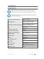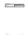
1
Model 8000-050 RF Power Amplifier User Manual ETS-Lindgren Inc. reserves the right to make changes to any products herein to improve functioning or design. Although the information in this document has been carefully reviewed and is believed to be reliable, ETS-Lindgren does not assume any liability arising out of the application or use of any product or circuit described herein; nor does it convey any license under its patent rights nor the rights of others. All trademarks are the property of their respective owners. © Copyright 2014 by ETS-Lindgren Inc. All Rights Reserved. No part of this document may be copied by any means without written permission from ETS-Lindgren Inc. Trademarks used in this document: The ETS-Lindgren logo is a registered trademark and Calibration Services Plus is a trademark of ETS-Lindgren Inc. Revision Record MANUAL, 8000-050 | Part #399633, Rev. A Revision Description Date A Initial Release October, 2014 ii www.ets-lindgren.com Table of Contents Notes, Cautions, and Warnings ......................................................................... v Safety Information .............................................................................................. v 1.0 Introduction ................................................................................................... 7 Standard Configuration ....................................................................................................... 7 2.0 Maintenance .................................................................................................. 9 Service Procedures ............................................................................................................ 9 Contacting ETS-Lindgren ............................................................................................. 9 Sending a Component for Service ............................................................................... 9 3.0 Specifications.............................................................................................. 11 Electrical Specifications .................................................................................................... 11 Physical Specifications ..................................................................................................... 12 4.0 Before You Begin ........................................................................................ 13 Unpacking ......................................................................................................................... 13 Safety Information ............................................................................................................ 13 Warnings........................................................................................................................... 14 5.0 Installation ................................................................................................... 15 Mains Input ....................................................................................................................... 15 Amplifier Protection .......................................................................................................... 15 6.0 Operation ..................................................................................................... 17 Equipment Use ................................................................................................................. 17 Mains Switch..................................................................................................................... 17 Standby/Operate Switch (Centre Unit) ............................................................................. 17 Fault Indicator (Red LED) ................................................................................................. 18 Interlock Indicator (Orange LED) ...................................................................................... 18 Local Lockout Indicator ..................................................................................................... 18 RF Input (Either Front or Rear Panel Mounted) ............................................................... 18 RF Output (Either Front or Rear Panel Mounted) ............................................................ 18 Air Inlet.............................................................................................................................. 19 Safety Interlock ................................................................................................................. 19 Fan Outlet ......................................................................................................................... 19 Appendix A: Warranty ...................................................................................... 21 Scope and Duration of Warranties ................................................................................... 21 Warranty Exclusions ......................................................................................................... 22 www.ets-lindgren.com iii Buyer’s Remedies ............................................................................................................ 22 Appendix B: EC Declaration of Conformity .................................................... 25 iv www.ets-lindgren.com Notes, Cautions, and Warnings Note: Denotes helpful information intended to provide tips for better use of the product. CAUTION: Denotes a hazard. Failure to follow instructions could result in minor personal injury and/or property damage. Included text gives proper procedures. WARNING: Denotes a hazard. Failure to follow instructions could result in SEVERE personal injury and/or property damage. Included text gives proper procedures. Safety Information Warning: Avoid exceeding the stated maximum input level as this can cause a risk of damaging the equipment. Warning: There is a significant risk of an electrical or burn hazard, to avoid this always ensure the output is terminated prior to switching on the equipment. Protective Earth Ground (Safety Ground): Indicates protective earth terminal. You should provide uninterruptible safety earth ground from the main power source to the product input wiring terminals, power cord, or supplied power cord set. Waste Electrical and Electronic Equipment (WEEE) Directive: (European Union) At end of useful life, this product should be deposited at an appropriate waste disposal facility for recycling and disposal. Do not dispose of with household waste. www.ets-lindgren.com v This page intentionally left blank. vi www.ets-lindgren.com 1.0 Introduction The ETS-Lindgren Model 8000-050 RF Power Amplifier is capable of supplying a minimum of 12 watts into a 50 ohm load over the frequency range 800MHz to 3100MHz. The amplifier is designed with sufficient gain so that it may be used with normal output levels of signal sources. A safety interlock on the rear panel is also provided, which will mute the amplifier when grounded. The unit is powered by a switched mode power supply for high efficiency, high power factor, and a wide voltage range operation. The unit is air cooled with integral fans and is protected against faulty cooling by excess temperature sensing. A front panel fault indicator is provided to indicate over-temperature. The amplifier is designed for rugged operation into a variety of loads and is primarily intended for use as an RF power source for EMC susceptibility testing, but is also applicable to other systems requiring a wide-band linear amplifier. This amplifier is designated as Professional Equipment and should not be operated by untrained staff. As this product has the capability to generate high levels of RF energy it is not intended for use in a residential environment. Standard Configuration The 8000-050 amplifier comes either as a bench unit or for fitting into a19-inch rack. The RF connectors are N type input which are located either on the front or rear panel of the amplifier. www.ets-lindgren.com Introduction 7 This page intentionally left blank. 8 Introduction www.ets-lindgren.com 2.0 Maintenance If you have any questions concerning maintenance or if the amplifier system is misoperating, contact ETS-Lindgren Customer Service. See Service Procedures for contact information. CAUTION: Before performing any maintenance, follow the information provided in Before You Begin on page 13. WARNING: There are no user serviceable parts within the RF Power Amplifier system. To prevent electrical shock, DO NOT remove covers. Warranty will be void if the covers are opened. WARRANTY ALWAYS UNPLUG THE UNIT BEFORE CLEANING. Clean the exterior of the cabinet using a damp cloth. Service Procedures CONTACTING ETS-LINDGREN Note: Please see www.ets-lindgren.com for a list of ETS-Lindgren offices, including phone and email contact information. SENDING A COMPONENT FOR SERVICE 1. Contact ETS-Lindgren Customer Service to obtain a Service Request Order (SRO). 2. Briefly describe the problem in writing. Give details regarding the observed symptom(s) or error codes, and whether the problem is constant or intermittent in nature. Please include the date(s), the service representative you spoke with, and the nature of the conversation. Include the serial number of the item being returned. 3. Package the system or component carefully. If possible, use the original packing materials or carrying case to return a system or system component to ETS-Lindgren. www.ets-lindgren.com Maintenance 9 This page intentionally left blank. 10 Maintenance www.ets-lindgren.com 3.0 Specifications Electrical Specifications Note: The third order intercept point is a nominal value as its calculation depends upon the power level at which distortion measurements are made. Note: Output VSWR tolerance is specified for excitation within the permitted levels and frequency range. Frequency Range (Instantaneous) Rated Output Power Output Power at 1dB Gain Compression 800MHz – 3100MHz 12W Minimum (800MHz – 3GHz) 10W Minimum (3GHz – 3.1GHz) 10W Minimum (800MHz – 3GHz) 8W Minimum (3GHz – 3.1GHz) Gain 41dB Minimum Third Order Intercept Point 54dBm Gain Variation with Frequency +/- 2.5dB Harmonics at 10W Output Power (800MHz – 3GHz) Better than -20dBc Output Impedance 50 Ohms Stability Unconditional Output VSWR Tolerance Infinity:1 Input VSWR 2:1 RF Connector Style Type N Female Safety Interlock BNC Female, s/c and o/c to mute USB/GPIB Interface Optional www.ets-lindgren.com Specifications 11 Physical Specifications Case Dimensions 19 inch, 3U Rack, 440mm deep Weight 7 kg (15.4 lb) 12 Specifications www.ets-lindgren.com 4.0 Before You Begin CAUTION: Before connecting any components, follow the information provided in Safety Symbols on page v. Unpacking The 8000-050 amplifier is supplied with the following contents: Power Cable (10A) Spare Fuse (T 3.15A H 250V 20mm) User Manual (This document) Calibration Test Report If any signs of damage are found no attempt should be made to install or operate the amplifier system. Contact ETS-Lindgren Customer Service immediately to report the problem. If the shipping carton has been damaged, retain the shipping carton and packing material for the carrier's inspection. Check that the equipment is complete and is in an undamaged condition, and then contact ETS-Lindgren Customer Service for further advice. Safety Information This RF amplifier has been designed and tested in accordance with BS EN61010-1 and has been supplied in a safe condition. This manual contains warning information which must be followed to ensure safe operation and to retain the apparatus in a safe condition. This apparatus does not incorporate components liable to explode or implode during normal operating conditions. In normal operating conditions this apparatus does not liberate injurious or poisonous gases. Sound levels of this apparatus in a rack are below 85dBA as required by EN61010-1. www.ets-lindgren.com Before You Begin 13 If local regulations have a lower limit, appropriate action should be taken in line with the local regulations so as to comply. This apparatus is of Installation Category 2. Warnings WARNING: This apparatus is capable of delivering harmful levels of radio frequency power. Ensure at all times during operation that the RF output is properly terminated with an adequately rated termination or transducer and that the cables and connectors attached to the apparatus are in good condition. The mains plug shall only be inserted in a socket outlet provided with a protective earth contact. The protective action must not be negated by the use of an extension cord without a protective conductor. The opening of covers or removal of parts is likely to expose live parts. This apparatus must only be serviced by qualified service personnel and must be disconnected from all voltage sources before it is opened for adjustment, replacement, maintenance, or repair. Make sure that only fuses of the required rated current and of the specified type are used for replacement. The use of makeshift fuses and the short-circuiting of fuse holders are prohibited. 14 Before You Begin www.ets-lindgren.com 5.0 Installation CAUTION: Before connecting any components, follow the information provided in Before You Begin on page 13. Mains Input Mains input is via a 10A power cable (supplied). Amplifier Protection The amplifier is protected by a fuse of the following rating, T 3.15A H 250V 20mm. This instrument must be earthed. WARNING: If the rack mounting option has been selected, the unit must be installed in the rack using a suitable tray or runners. The amplifier must not be supported only by the front panels. www.ets-lindgren.com Installation 15 This page intentionally left blank. 16 Installation www.ets-lindgren.com 6.0 Operation CAUTION: Before placing into operation, follow the information provided in Before You Begin on page 13. Note: Make sure you are satisfied with the contents and condition of your amplifier prior to placing it into operation. Warning: Avoid exceeding the stated maximum input level as this can cause a risk of damaging the equipment. Warning: There is a significant risk of an electrical or burn hazard; to avoid this, always ensure the output is terminated into a suitable load prior to switching on the equipment. Equipment Use The equipment must only be used for its intended purpose. All parts of the equipment must remain connected to ensure that protective circuits operate. Disconnecting parts of the equipment may impair operation and safety. Mains Switch The amplifier is switched on or off by pressing the mains switch on the rear panel of the amplifier. Standby/Operate Switch (Centre Unit) Pressing the standby/operate switch toggles the state of the amplifier between Standby and Operate modes. The blue halo indicator flashes in Standby mode, whereas steady blue indicates Operate mode. www.ets-lindgren.com Operation 17 Fault Indicator (Red LED) Should a fault be detected, the red LED on the amplifier front panel will be illuminated. The amplifier will be forced into standby mode and the unit will cease to function. This action is latching, therefore only when the fault has been cleared can the amplifier be reset; this is done by pressing the standby/operate switch. The reasons for the system fault light to illuminate are as follows: Excess module temperature Air cooling failure (fans failing to operate) Interlock Indicator (Orange LED) When the rear panel interlock is activated the interlock indicator will illuminate and the amplifier gain stages will all be turned off. This action is latching; therefore, the amplifier will return to Standby mode when the interlock is released. Local Lockout Indicator This indicator is used when the USB/GPIB option is fitted. Refer to the separate Remote Control Interface manual supplied. RF Input (Either Front or Rear Panel Mounted) The RF input will accept a signal from an RF generator. This input must be within the operating frequency range of the 8000-050 amplifier. An amplitude of up to 0dBm will be sufficient to saturate the amplifier. Operation outside the specified frequency range should not be attempted as it may subject the amplifier to undue internal stress. RF Output (Either Front or Rear Panel Mounted) WARNING: The centre conductor of the RF output represents a severe burn hazard to personnel. Never operate the amplifier without a proper termination or with defective cables or connectors. This connector must be suitably terminated at all times during operation. Ensure that the cable is capable of handling the power available, which may be as much as 20 watts. 18 Operation www.ets-lindgren.com Air Inlet This amplifier requires a free air supply for cooling; the front air inlet must not be restricted. Safety Interlock A dual interlock system can be operated by applying either short circuit (S/C) or open circuit (O/C) to mute the amplifier. In order for the amplifier to operate, the Interlock BNC connector must be S/C and the Interlock must be O/C. If the Interlock is O/C or the Interlock is S/C the amplifier will be muted. The amplifier is delivered without the interlock applied and will be ready to operate. The interlock function is latching so when the interlock is removed the amplifier will be in standby mode. Press the standby/operate switch to return to normal operation. Current drawn from the interlock BNC connectors under short circuit conditions will typically be 2.8mA. Fan Outlet This amplifier requires a free air supply for cooling; the rear air outlets must not be restricted. www.ets-lindgren.com Operation 19 This page intentionally left blank. 20 Operation www.ets-lindgren.com Appendix A: Warranty Scope and Duration of Warranties Seller warrants to Buyer that the Products to be delivered hereunder will be (1) free from defects in material, manufacturing workmanship, and title, and (2) conform to the Seller’s applicable product descriptions and specifications, if any, contained in or attached to Seller’s quotation. If no product descriptions or specifications are contained in or attached to the quotation, Seller’s applicable product descriptions and specifications in effect on the date of shipment shall apply. The criteria for all testing shall be Seller’s applicable product specifications utilizing factory-specified calibration and test procedures and instruments. All product warranties, except the warranty of title, and all remedies for warranty failures are limited to three years. Product Warranted Duration of Warranty Period Model 8000-050, RF Power Amplifier Three Year(s) Any product or part furnished to Buyer during the warranty period to correct a warranty failure shall be warranted to the extent of the unexpired term of the warranty applicable to the repaired or replaced product. The warranty period shall commence on the date the product is delivered to Buyer; however, if Seller assembles the product, or provides technical direction of such assembly, the warranty period for such product shall commence on the date the assembly of the product is complete. Notwithstanding the foregoing, in the event that the assembly is delayed for a total of thirty (30) days or more from the date of delivery for any reason or reasons for which Seller is not responsible, the warranty period for such product may, at Seller’s options, commence on the thirtieth (30th) day from the date such product is delivered to Buyer. Buyer shall promptly inspect all products upon delivery. No claims for shortages will be allowed unless shortages are reported to Seller in writing within ten (10) days after delivery. No other claims against Seller will be allowed unless asserted in writing within thirty (30) days after delivery (or assembly if the products are to be assembled by Seller) or, in the case of alleged breach of warranty, within the applicable warranty period. www.ets-lindgren.com Warranty 21 Warranty Exclusions Except as set forth in any applicable patent indemnity, the foregoing warranties are exclusive and in lieu of all other warranties, whether written, oral, express, implied, or statutory. EXCEPT AS EXPRESSLY STATED ABOVE, SELLER MAKES NO WARRANTY, EXPRESS OR IMPLIED, BY STATUTE OR OTHERWISE, WHETHER OF MERCHANTABILITY OR FITNESS FOR ANY PARTICULAR PURPOSE OR USE OR OTHERWISE ON THE PRODUCTS, OR ON ANY PARTS OR LABOR FURNISHED DURING THE SALE, DELIVERY OR SERVICING OF THE PRODUCTS. THERE ARE NO WARRANTIES WHICH EXTEND BEYOND THE DESCRIPTION ON THE FACE HEREOF. Warranty coverage does not include any defect or performance deficiency (including failure to conform to product descriptions or specifications) which results, in whole or in part, from (1) negligent storage or handling of the product by Buyer, its employees, agents, or contractors, (2) failure of Buyer to prepare the site or provide an operating environmental condition in compliance with any applicable instructions or recommendations of Seller, (3) absence of any product, component, or accessory recommended by Seller but omitted at Buyer’s direction, (4) any design, specification, or instruction furnished by Buyer, its employees, agents or contractors, (5) any alteration of the product by persons other than Seller, (6) combining Seller’s product with any product furnished by others, (7) combining incompatible products of Seller, (8) interference with the radio frequency fields due to conditions or causes outside the product as furnished by Seller, (9) improper or extraordinary use of the product, or failure to comply with any applicable instructions or recommendations of Seller including maintenance, calibration and cleaning procedures and intervals, or (10) acts of God, acts of civil or military authority, fires, floods, strikes or other labor disturbances, war, riot, or any other causes beyond the reasonable control of Seller. This warranty does not include (1) batteries, (2) cables, (3) gasket, (4) fingerstock, or any item that is designed to be consumable. Seller does not warranty products of others which are not included in Seller’s published price lists. Buyer’s Remedies If Seller determines that any product fails to meet any warranty during the applicable warranty period, Seller shall correct any such failure by either, at its option, repairing, adjusting, or replacing without charge to Buyer any defective or nonconforming product, or part or parts of the product. Seller shall have the option to furnish either new or exchange replacement parts or assemblies. Warranty service shall be performed at the Seller’s factory, or the Buyer’s site at the sole discretion of the Seller. Within the warranty period, the Buyer shall be responsible for all transportation to the Seller’s factory, and the Seller shall be responsible for transportation of goods to the Buyer’s site. 22 Warranty www.ets-lindgren.com Within the contiguous 48 United States, warranty service performed during the applicable warranty period will be performed without charge to Buyer during Seller’s normal business hours. After the warranty period, service will be performed at Seller’s prevailing service rates. Subject to the availability of personnel, after-hours service is available upon request at an additional charge. Outside the contiguous 48 United States, travel and per diem expenses, when required, shall be the responsibility of the Buyer, or End User, whichever is applicable regardless of the warranty period. The remedies set forth herein are conditioned upon Buyer promptly notifying Seller within the applicable warranty period of any defect or non-conformance and making the product available for correction. The preceding paragraphs set forth Buyer’s exclusive remedies and Seller’s sole liability for claims based on failure of the products to meet any warranty, whether the claim is in contract, warranty, tort (including negligence and strict liability) or otherwise, and however instituted, and, upon the expiration of the applicable warranty period, all such liability shall terminate. IN NO EVENT SHALL SELLER BE LIABLE TO BUYER FOR ANY SPECIAL, INDIRECT, INCIDENTAL OR CONSEQUENTIAL DAMAGES OF ANY KIND ARISING OUT OF, OR AS A RESULT OF, THE SALE, DELIVERY, NON-DELIVERY, SERVICING, ASSEMBLING, USE OR LOSS OF USE OF THE PRODUCTS OR ANY PART THEREOF, OR FOR ANY CHARGES OR EXPENSES OF ANY NATURE INCURRED WITHOUT SELLER’S WRITTEN CONSENT DESPITE ANY NEGLIGENCE ON BEHALF OF THE SELLER. IN NO EVENT SHALL SELLER’S LIABILITIES UNDER ANY CLAIM MADE BY BUYER EXCEED THE PURCHASE PRICE OF THE PRODUCT IN RESPECT OF WHICH DAMAGES ARE CLAIMED. This agreement shall be construed in accordance with laws of the State of Texas. In the event that any provision hereof shall violate any applicable statute, ordinance, or rule of law, such provision shall be ineffective to the extent of such violation without invalidating any other provision hereof. Any controversy or claim arising out of or relating to the sale, delivery, non-delivery, servicing, assembling, use or loss of use of the products or any part thereof or for any charges or expenses in connection therewith shall be settled in Austin, Texas by arbitration in accordance with the Rules of the American Arbitration Association, and judgment upon the award rendered by the Arbitrator may be entered in either the Federal District Court for the Western District of Texas or the State District Court in Austin, Texas, all of the parties hereto consenting to personal jurisdiction of the venue of such court and hereby waive the right to demand a jury trial under any of these actions. www.ets-lindgren.com Warranty 23 This page intentionally left blank. 24 Warranty www.ets-lindgren.com Appendix B: EC Declaration of Conformity ETS-Lindgren Inc. declares these products to be in conformity with the following standards, following the provisions of EMC Directive 2004/108/EC and Low Voltage Directive 2006/95/EC: Model 8000-050, RF Power Amplifier Emission: EN 61326-1:2006, Class A Electrical equipment for measurement, control, and laboratory use. Immunity: EN 61326-1:2006, Industrial level, performance criteria A Electrical equipment for measurement, control, and laboratory use. Safety: EN 61010-1:2010 Safety requirements for electrical equipment for measurement, control, and laboratory use. Technical Construction Files are available upon request. www.ets-lindgren.com EC Declaration of Conformity 25