1
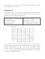
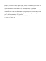
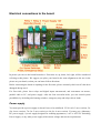
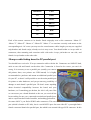
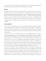
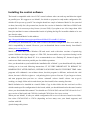
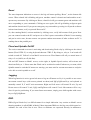
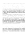
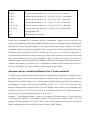
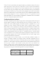
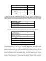
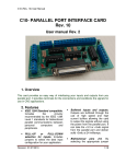
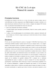
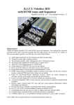
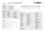
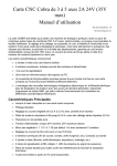
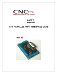
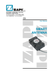
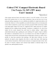
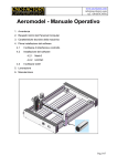
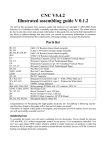
2-to-6 axes Cnc driver kit
User manual
Hardware Revision: 6.1.0 / 6.1.1
Firmware Revision: 6.0
User Manual Revision: 0.2
Main features
Congratulations for buying 2-to-6 axes Cnc driver kit. The board you just bought, either De Luxe
(to be soldered) or Chiavi in mano (already assembled and tested), is the best choice to control a 3
axes milling machine, a turn table, or any kind of up-to-6 axes CNC machine. The main features of
the controlling board are:
•
up to 6 interpolated axes (coordinated moving)
•
5 digital inputs (for home switches, limit switches, probe, emergency stop, etc.)
•
2 relays outputs (turn on/switch off an electric power tool, vacuum cleaner, working area
lighter, etc.). Please note that 6 axes version of the board does not support relays.
Disclaimer
The text you are reading (User Manual) is Copyright © 2004-2006, Paolo Sancono. It is strictly
forbidden to reproduce any part of this text by any mean and for any purpose. You are entitled to
read it on screen or print it out if you own the board this manual refers to, but printout must be kept
in the same room as the board, otherwise you must destroy printout. We believe information hereby
reported to be correct, and any effort possible as been made, but we take no responsibility for any
damage, wich directly or indirectly may arise due to erroneous information hereby present. What
the board and supplied motors can do has been shown while selling the product. To verify that the
products fulfils your needs is totally at you, the user. To verify that this device complies with
security standards, EMI standards and any other is totally up to the user, the product is sold without
CE marking for hobbistic/experimental/educational purposes. You must verify that the board is
electrically compatible with your PC, your power supply, and any other device you connect the
board to. We take no responsibility for direct or indirect damage which may arise after operating or
misoperating the board and supplied motors. We suggest you plug the board to an expansion card
with an additional parallel port, so that the risk of damaging main board is reduced to a minimum,
even if we can tell you we used the board plugged to main parallel port for months without damage
of any sort. Stepper motors are checked just before shipping and leave the company working. We
don’t accept claims for non-working motors. However, if something bad should happen, just contact
us and probably any issue may be solved.
Stepper Motors
This board was designed to work together with the supplied stepper motors. Don’t use the board
with other motors or the motors with other boards, if you don’t know what you are doing. You can
easily damage ours motors or board, or the third part ones.
Electrical Characteristics: 12V/600mA/20Ω/phase Torque @ 30 rpm > 4,6 kgfcm
Driving: Unipolar 2 phases ON
Torque @ 150 rpm: >3,7 kgfcm
1,8°/step = 200 step/revolution
Maximum speed with no load >330 rpm
Mounting: Standard Nema 31
Power consumption: 14W (2 phases ON)
The above graph reports torque generated for each angular velocity. Up to 150 rpm the decay in
torque is not so big, and we suggest this speed for rapid movements on your machine, and smaller
speeds for working movements. If you mount an M10 lead screw, which advances 1,5mm per
revolutions, we obtain, at 150 rpm suggested for rapids, a forward movement of 280 mm / minute
(if two axes are moving at the same time in a 45° diagonal at 280 mm/minute rate, you obtain 400
mm/minute rate of the combined movement).
For the job (engraving) you can use inferior speeds, for sample 150 mm/minute for soft plastic, and
less than that for stronger materials. For sample 120 mm/minute for soft wood, 80 mm/minute for
vetronite (PCB material), 50 mm/minute for hard wood, 40 mm/minute for aluminium.
Of course you must experiment on your machine the suitable speed for different kind of materials,
you must take into account also your milling bit, power of your electrical power tool, and the depth
of engraving you are using in a single pass in your job. The numbers we gave are for guidance and
serve as a good starting point for your experiments.
Motors’ mounting is standard Nema 31. It consists in 4 M6 holes with their centres on the vertexes
of a square of 47,34 mm side.
Electrical connections to the board
In picture you can see the board from above. From now on, up, down, left, right, will be considered
referring to this picture. We suggest you place your board in the same alignment as the one in the
picture on your bench, so that you can better follow directions.
Before connecting the board to anything for the first time, please accurately check out if it has been
damaged during travel.
For first trials, please leave relays and digital inputs unconnected, and concentrate on motors,
parallel cable to PC, and power supply. After the first successful trials, you can extend system
possibilities by including also homing switches, emergency stop and relays-driven loads.
Power supply
You must provide a power supply (it doesn’t have to be stabilized) 12V 4A (for 3 axes version), 5A
(for 4 axes version), 7A (for 5 axes version) or 8A (for 6 axes version). You may use a laboratory
DC power supply, a power supply designed for radiating apparatuses, a AT or ATX PC Switching
Power Supply, or any other power supply which meets voltage and current requirements.
If you plan to use a PC switching power supply, it may be useful to know that wires on the molex
connectors, follow this colour scheme: black – 0V, red – 5V, yellow – 12V. 12V DC can be
obtained between black (negative pole) and yellow (positive pole) wires. The majority of PC power
supplies require a minimum load on 5V line to assure there’s good stabilization on both 5V and
12V lines. In such cases, please connect a power resistor experimenting which is the minimum load
for you supply. Usually a 4,7Ω / 10W resistor is a good starting point for experiments and should
suffice in most cases. It may be a good idea to mount this power resistor directly inside the power
supply, fixing it on the heat sinks. This kind of modifications must be operated by qualified
personnel, who knows how to operate and what to do. Inside PC power supplies there are lethal
voltages even after disconnecting mains, so please be careful. We take no responsibility of any
damage you could receive by following directions or suggestions hereby present.
Power supply connects to the screw terminal middle-way on the upper side of the board (referring
to the picture above). The board has no protection against polarity inversion, so be careful to
connect negative pole to the left-most (relative to the picture above, the screw nearer to the other 2
screw terminals) and positive pole to the right-most (relative to the picture above) screw. Please
note that + (“plus”) and – (“minus”) signs are present on the serigraphy to help you connect power
supply in the correct manner.
It is a very good idea to provide a main switch, which opens one of the two supply wires. If your
power supply already comes with its main switch, you have no need to add another one. However, it
is important to leave the board switched off until you run the control software on PC, to avoid
unwanted moves on the machine while PC is doing something with the parallel port on its own.
Stepper Motors
Each motor connects to its 6 ways pinheader connector. Pin headers let you insert
connector reversed; if you place it the wrong
way, motor won’t turn, but you won’t
damage anything. Serigraphy on board next
to connectors (“WhBkBrYlRdBl”) helps
you orient the motors’ connector in the
correct way. In fact the string is constituted
by mnemonics of the wires colors to the
motor, following this table:
Mnemonic
Color
Wh
WHite
Bk
BlacK
Br
BRown
Yl
YeLlow
Rd
ReD
Bl
BLue
Each of the motors connects to its header. Read serigraphy next to the connectors “Motor X”
“Motor Y” “Motor Z” “Motor A” “Motor B” “Motor C” to associate correctly each motor on the
corresponding axis. Of course you may need to extend motors cables length: you may use supplied
strip-headers and female strips, already cut in 6-ways rows. You should solder a 6-ways cable to
connectors, thus mounting and extension cable with male 6-ways pin-header on one side, and
female 6-ways header on the other side.
25-ways cable linking board to PC parallel port
You should have received a 25-ways connection cable with the kit. Connectors are SubD-25 kind,
male on one side and female on the other side. Connection is forced to be correct, you can’t do
wrong. It is necessary to use a parallel port (usually you connect
old printers there, new printers use USB instead). Is is highly
recommended to purchase and mount an additional parallel port
for your PC, so that it’s still possible to use the main parallel port
for printer or other hardware, and you prevent any possibility of
damage to main board’s parallel port. We don’t assure anything
about electrical compatibility between the board and your
hardware, so if something gets broken, the risk is all yours. But
we can assure you a board identical to the one you received has
been working for one year, connected to main board parallel port,
and we experienced no kind of troubles, and nothing got broken.
On some old PC’s you find a SUB25 male connectors. This one is not to be confused with parallel
port (which is female on PC side), but is a serial RS232 port. On some older PC’s you might find a
female connector identical to parallel port, but which is an external old-type SCSI connector. In this
rare case you must ask who assembled the PC which connector is the parallel port and which one
the SCSI connector, and you should use the parallel connector for the board.
Relays
On board you will find 2 relays for 2 on/off outputs (relays are not present on 6 axes version of the
board). Two two-ways screw terminals provide access to normally open relay switch. It is possible
to control loads with any voltage because there is no electrical link between relays switch contacts
and the rest of the circuit. The left-most relay is relay n. 1, usually devoted to spindle control,
typically a power tool such drill or mill. The right-most relay is relay n. 2, controlled by flood
function in software. Typically you connect a vacuum dust cleaner, a light source for working area,
a cooling system, or any other thing you may find useful to control by PC during automated
machining.
Limit switches
5 limit switches can be linked to the 10-ways screw terminal on bottom left of the board. Software
can be configured both for normally open or normally closed switches. Initially it is configured for
normally open switches, so that they are not active if nothing is connected to the board. Normally
closed switches are safer because if a wire gets interrupted, the condition is immediately reported as
a switch pressed.
The first two places of screw terminal on right are for X axis homing switch, next 2 positions
(starting count from right) are for Y axis home switch; follows Z axis home switch in the middle 2
screw terminals. Home switches serve for an absolute referencing on the machine, and are not
needed if you prefer zeroing directly on the work piece. Home switch can be mounted in any
position on axis run (so to say, even middle-way), but typically it is mounted at one of the two
extremes of the axis, and it serves both as home switch and as limit switch. You can mount more
limit switches on the edges opposite to the home switch for each axis. These limit switches can be
paralleled (normally open setup) or put in series (normally closed setup) and connected all together
to the fourth couple of screw terminals, counting from right (screw terminal n. 7 and n. 8).
Last two screw terminal (n.9 and n.10 counting from right) are for an hardware emergency stop
which will cease immediately motor movements and remove power from spindle. Flood will remain
in same status as before. Emergency stop function is due to software, the board simply reports to the
software corresponding switch has been pressed, but does not itself stop motor motion, so this
emergency stop is no the safest approach. You should provide other means of protection for your
machine, such as a circuit which will remove power from board when emergency stop is pressed, to
be safer. We take no responsibility for any damage you may experience by using the board. If you
use the board, all risks are up to you.
Installing the control software
The board is compatible with a lot of CNC control software who can send step and direction signal
on parallel port. We suggest to use Mach3, for which we prepared a ready-made configuration file
which will let you set up your PC for using the board in a couple of minutes. Mach3 is free (not trial
or demo, but really free) for personal use, but the free version is limited to 1000 lines of ISO/Gcode
toolpath file. It is necessary to buy license (it costs 150$) if you plan to use it for longer than 1000
lines jobs and don’t want to withstand the hassle of splitting the big file in smaller chunks to be run
one after the other.
You can download Mach3 at this address:
http://ideegeniali.altervista.org/progetti/kitcnc/dl/Mach3VersionR1.83.010.exe
the version you download here is the same version with which configuration files were made, so
100% compatibility is assured. However, you can download latest version directly from Mach3
editors, at www.artofcnc.ca
Mach3 will work only under Windows XP and won’t work with other versions of operativing
system. Software developers suggest a 1 GHz CPU, but no troubles were experienced using it with
an Athlon 550 MHz Cpu Based PC. It is recommended to use a Desktop PC, because Laptop PC
send our too little current on parallel port for reliable operations.
Once you download on your hard disk the installation file of Mach 3, you should install it by double
clicking on its icon and following instructions. IT IS VERY IMPORTANT TO REBOOT PC
IMMEDIATELY AFTER INSTALL, BEFORE LAUNCHING MACH3 THE FIRST TIME. Other
programs will withstand a run without reboot, but this program is different, and needs the vital
reboot, because it HAS to register a .vxd pulseing driver prior to first run. If you forget to reboot,
and start program, then you have to –reboot –uninstall –reboot –install –reboot –run to get it
working, so simply follow advice and reboot just after install, before running first time.
Mach3 defaults to be installed in c:\mach3 folder. Copy in this folder also the .xml and .set files
which contain specific configuration for the board, which you should download at the same location
where you downloaded this manual. You should use CNC610-2345.xml and CNC610.set for 2 to 5
axes version of the board, and CNC610-6.xml and CNC610.set for 6 axes version.
When you run Mach3, it asks you which configuration file to use of the ones found in its folder.
Just select CNC610-2345 or CNC6 (depending on how many axes your board supports) and
confirm with OK.
@todo change-this-picture
To select CNC610 configuration among the other ones present.
Program will run and you will se main screen of the program. This screen can get you confused at
first sight for quantity and different kind of controls available, but you will learn soon how to
master the basic functions. Don’t connect the board to the PC for now, first learn something about
the program main screen, then connect the board and start moving motors.
Main screen of Mach3
Reset
The most important indication on screen is the big red button spelling “Reset”, on the bottom left
corner. When related led is blinking red/green, machine control is deactivated and machine won’t
operate any movement. By clicking on Reset, related led will get constant green and machine will
move responding to your commands. Clicking on reset again, led will go blinking red/green again
and machine deactivated. If you put an emergency stop on machine, pressing it will put the software
in deactivated status, as if you pressed Reset on PC.
So, after running Mach3, activate machine by clicking reset, verify led becomes fixed green. Now
you can connect board to the PC and power it on. Don’t power on machine if Mach3 is not running
and put in active state, because motors can present random movements if other software on PC is
sending data to the parallel port.
Flood and Spindle On/Off
The easiest command on screen is activating and deactivating flood relay by clicking on the related
button (Flood CTRL-F) or using keyboard shortcut CTRL-F. By doing so, relay n. 2 on board will
switch on and off. Yellow Led on Mach3 screen next to Flood button will tell you actual state of
relay n.2: on (led lit) or off (led dim).
ON and OFF button on Mach3 screen, on the right, in Spindle Speed section, will activate and
deactivate Relay n. 1. Please note that Flood can be switched on and off whenever you want, while
Spindle cannot be switched if motors are moving: you must wait for current movement to end prior
to be able to switch spindle on or off.
Jogging
When Jog function is active (green leds next to Jog on-off button are lit), it is possible to use cursor
movement control keys (with arrows painted on them) and PgUp PgDown Keys on keyboard to
manually control X, Y and Z axis movements. Right and Left arrow will control X axis, Up and
Down arrow will control Y axis, PgUp and PgDown will control Z axis. Movements will be very
slow for precise positioning. If you want faster movements, simply press shift together with cursor
keys or PgUp/PgDown.
DRO
DRO (Digital Read Out) is a difficult name for a simple indication. Any section on Mach3 screen
showing numbers is called DRO in Mach3. Most important DROs are the big ones which actual coordinates for each of the first 4 axes. These co-ordinates are expressed directly in millimetres.
Typically X=0 Y=0 corresponds to a vertex of the object to be machined. Z=0 typically is when the
tool contacts the superior surface of the material, so Z>0 means tool is outside the object, on free air
above it, Z<0 means the tool is inside the object milling or cutting it, at the depth of the actual Z coordinate. It is possible to invert positive and negative verse for each axis on menu Config / ports &
Pins / Motor Output / Dir Low Active column. Changing V with X on this column will invert
positive rotating verse for the corresponding motor. Typically, looking at your milling machine
table from above, positive X should be towards right, positive Y towards up, positive Z towards you
who are looking from above (i.e. positive Z outside the material, towards free air, negative Z inside
the material, towards the table). If you use more than 3 axes, the coordinates on the extra axes
(called A B and C) may represent different things depending on your machine setup. For sample, if
one of the axis is a rotative one on your machine, its coordinates are usually expressed in degrees
instead of millimiters.
Mach3 uses a complex offset system to shift co-ordinates origin (zero, zero, zero) in a well
determined point on object being machined, from where the machining job (provided as an
ISO/Gcode file) will start. Mach3 is able to set up different offset systems, to switch from one to the
other, to compensate for different heights of different tools, but usually you don’t need to take care
of all this stuff. Usually you just manually jog to the starting position (a reference point on the
object), contact superior surface with the tool, and then click on “Zero X” “Zero Y” “Zero Z”
buttons. Internal offset systems will be adjusted to display 0, 0, 0 on co-ordinates DROs, .
ISO/Gcode file will follow the same co-ordinates offset you set on DROs, that is, job will start from
the point 0,0,0 where you just jogged to and zeroed the machine to. For the first 4 axes, zeroing
buttons are available on Mach3 Main Screen. For 5 and 6 axes machine, B and C zeroing buttons
are not available on main screen, but are accessible on “Diagnostics” screen.
Gcode
For some basic jobs, you can manually jog your machine around at the two available speeds, start
and stop spindle as needed, and complete your job, taking co-ordinates displayed as reference for
distance travelled (co-ordinates are expressed directly in millimetres). But typical use of CNC
machine is to execute a tool path written in the form of a ISO/Gcode tool path file. These files are
nothing more as plain ASCII text files, which you can edit with Windows Notepad, and which you
preferably save with .tap instead of .txt extension (but different programs use different extensions
for the very same thing. You may encounter .gc .iso and others which will work all well with
Mach3).
More simple – and most used – Gcode commands are these:
G0 (It’s Gee – Zero, not Gee – Ou) – Rapid Movement (at fastest speed motors can handle)
G1 – Slow Movement (at F-setted speed)
F – Set slow movement speed in millimetres per minute
M3 – Switch Spindle ON
M5 – Switch Spindle OFF
M8 – Switch Flood ON
M9 – Switch Flood OFF
M30 – End of program (tool path and program are synonyms in this contexxt)
These commands are to be put in an ASCII text file and saved preferably with .tap extension. You
can load the file in Mach3 by clicking Load G-Code button. You can execute just-loaded tool path
by clicking on Cycle Start (green button), and stop it prematurely by clicking on Stop (red button).
Of course, a job can be interrupted also by clicking on Reset button or pressing the hardware
emergency stop button.
MDI
You can tell Mach3 to execute Gcode commands without editing a text files, but inserting them one
after the other interactively with MDI (Manual Data Input). You just have to click on ENTER key
on keyboard, write the command (which will show up, as you type it, in yellow bar just under JOG
button on Mach3 Screen), confirm its execution by clicking ENTER, and exiting MDI modality by
clicking ENTER again. It is important to exit MDI modality after using it, because a lot of Mach3
functionality (including jogging) are disabled while you are entering MDI commands. Just try M3
M5 M8 M9 commands interactively, observing what happens on relays on board. If you need more
room to type long commands, you may switch to “Mdi” Mach3 screen instead of main one, which
is provided with a longer MDI bar than the main screen.
Gcode Example
This is a tool path example – we will engrave a 1 cm side square, and will engrave also one of the
two square diagonals. Before running the program, you should zero on material surface by manual
jogging the machine there and clicking on zeroing buttons.
G0 Z2
Rapid movement to Z = 2 (X=?, Y=?) – Outside object
M3
Switch on Spindle
G0 X0 Y0
Rapid movement to X = 0, Y = 0 (Z=2) – Travel to one vertex
G1 Z0 F100
Slow movement, speed 100 to Z = 0 (X=0, Y=0) – Contact object
G1 Z-0.2 F50
Slow movement, speed 50 a Z = -0.2 (X=0, Y=0) – Inside object
G1 X10
Slow movement, speed 50 a X = 10 (Y=0, Z=-0.2) – First side
G1 Y10
Slow movement, speed 50 a Y = 10 (X=10, Z=-0.2) – Second side
G1 X0
Slow movement, speed 50 a X = 0 (Y=10, Z=-0.2) – Third side
G1 Y0
Slow movement, speed 50 a Y = 0 (X=0, Z=-0.2) – Fourth side
G1 X10 Y10
Slow movement, speed 50 a X = 10 Y = 10 (Z=-0.2) – Diagonal
G1 Z2 F100
Slow movement, speed 100 a Z = 2 (X=0, Y=0) – Outside object
M5
Switch Spindle OFF
M30
End of program / tool path
Please note co-ordinates are expressed directly in millimetres. Speeds (a.k.a. Feed rates) are
expressed in millimetres per minute. Rapid movements (G0) are performed at the maximum speed
allowable by motors. Slow movements (G1) are performed at last set speed, which you set with F
commands in the tool path, or by writing the value of your choice on main screen in Mach3, section
Feed Rate. Please note that Feed rate is modal: once you set it to a value, preceding value is
overwritten and actual value is active until next set. Please also note that you can specify all of the
three axes co-ordinates in a G0 or G1 command, or only two of them, or just one, if movements is
along one single axis. Movements will be straight in 3D world, so motion will be interpolated (coordinated movements) if you specify 2 or 3 destination co-ordinates at the same time. Of course if
you have more than 3 axes (up to 6) Mach3 will interpulate on all of them.
Advance rate for revolution different from 1,5 mm/revolution
To output correct amount of steps to the motors, for requested travel in millimetres, Mach3 needs to
know how long an axis will travel for a complete revolution of the motor. On my machine, I used
M10 lead screws, which advance of 1.5 mm for each revolution. Motors are 200 step/revolution, so
step number to advance one unit (one millimetre) is 200 / 1.5 = 133.3333333 step/unit. This
number, calculated with a simple division, is the one Mach3 wants to know. For configuration file
provided, it is set to 133.3333333 for all axes. If your machine advances of a different length for
one revolution, you have to adjust this value to your needs.
Example1 – Your machine advances 1 mm for 1 revolution. 200 step/revolution / 1 units/revolution
= 200 step/unit. Example2 – Your machine advances 1.25 mm for one revolution: 200 / 1.25 = 160
steps per unit. This number (133.333333, 200 or 160 in our examples) is the one to be inserted in
Mach3 configuration screen accessible via menu Config / Motor Tuning.
Click on X Axis in Axis Selection, then input the number you calculated on bottom left, where it
spells “steps per unit”. Click on “Save Axis”. Then click on “Y Axis”, enter the correct number for
Y axis, and click “Save Axis”. Repeat for Z axis. If your machine has A, B or C axis, repeat again
for each of them. Once you’re finished, click on OK to end procedure. Mach3 can accept different
advancing rates for different axes. The procedure in this paragraph is only needed if your machine
advance rate is different from 1.5 mm/revolution, other wise basic configuration supplied with the
board is already configured for 1.5 mm / revolution for each axes. It is a good idea to exit and
launch again Mach3 to be sure the change in configuration is committed to disk. In fact Mach3
doesn’t save configuration updates until it is shut off.
Configuring third part software
The board is compatible with the totality of stepper motors control programs which send step and
direction signals on parallel port, which practically means all of this kind of software. Just to
mention some of the available programs, with which the board is compatible, here is a non
exhaustive list: Ninos, TurboCnc, KellyCam, Galaad, CeNeCe, CncPlayer, Master 5, Mach1,
Mach2, Mach3. A note of regard goes to TurboCnc (for Dos) and KellyCam (for Windows 98)
which are licensed completely free of charge, Galaad and Ninos are complete solutions which
include both a CAM (Computer Aided Manifacturing) and stepper motors control software, and
CeNeCe, a Spanish program, which is one of the few – or perhaps the only one – devoted to control
4-axes Cnc machines to cut out wings for plane models in polystirene by using a hot wire. There
exist specialized programs also for Linux and McIntosh which can control stepper motors
connected to the parallel port via the board.
If you are going to use one of these software, or one of the others available on market, it is
necessary to manually configure your program, because ready-made configuration files are
available only for Mach3 at the moment. On following tables you may find basic configuration
parameters, i.e. pins to which are tied electric signals on board. For other parameters setup (speed of
each axis, steps / revolution / unit of measure, etceteras, please refer to your software’s user
manual). The board expects a positive-edge-going pulses (the most common case) on step pin to
work properly. Please make sure your software uses positive-edge-going pulses and not negativeedge-going ones on step pins. See the following tables for correct pins configuration:
Output Signals, group 1
(from PC to Board)
Step Pin
Direction Pin
X axis
2
3
Y axis
4
5
Z axis
6
7
A axis
8
9
B axis (*)
17
16
C axis
1
14
(*) Please note Serigraphy on Board erroneously reports, for B axis, pin 16 for Step and pin 17 for
Direction instead of correct values shown on this Table. You might want to correct serigraphy with
a marker, putting a double-end arrow or overwriting erroneous numbers with correct ones on board.
Output Signals, group 2
(from PC to Board)
Pin
Relay #1 (Spindle)
1
Relay #2 (Flood)
14
Please note that Relays can’t be used together with C axis, because share same pins
Input Signals
(from Board to PC)
Pin
X Home (right-most)
10
Y Home
11
Z Home
12
Limit
13
E-Stop (left-most)
15
Information provided about input signals pin association, is handy even when you use Mach3, if
you plan to reconfigure it to best suit your needs, and want to reassign input signals to other
functions available in Mach3, instead of the one proposed in the original configuration supplied
with the board. This is easily done in the configuration windows accessible via config / ports and
pins / input signals menu in Mach3. You should specify, for each signal of interest, the number of
parallel port on which the signal has to be found (specify 1 for the first parallel port on PC, 0 not to
use that signal), and the pin at which it is tied. Mach3 lets you assign the same pin to different
signals. Be careful when doing so, because some combination are good and useful, others don’t
make sense and can lead to unexpected behaviours. For example, you may wire a lot of limit
switches (1 or 2 per each axis, so to say up to 12 switches all together) to the same input signal
(Limit signal), and tell Mach3 that that pin serves to all of the suitable Axis++ or Axis-- Limit
signals; on the other hand, usually you won’t share EStop signal with any another one. Please read
Mach3 user manual for hints on how to best use the different input signals available and reassign
them differently from the basic configuration proposed.
Happy Cnc’ing with your machine!