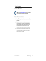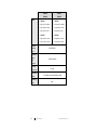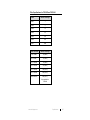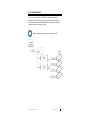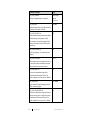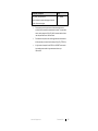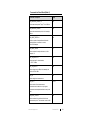
1
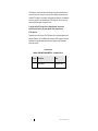
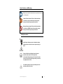
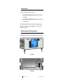
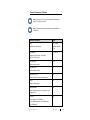
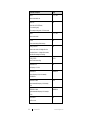
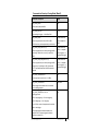
Models 7002-002, 7002-003, 7002-004, 7002-005 EMPower™ USB RF Power Sensor User Manual Models 7002-002 | 7002-003 | 7002-04 | 7002-05 ETS-Lindgren Inc. reserves the right to make changes to any product described herein in order to improve function, design, or for any other reason. Nothing contained herein shall constitute ETS-Lindgren Inc. assuming any liability whatsoever arising out of the application or use of any product or circuit described herein. ETS-Lindgren Inc. does not convey any license under its patent rights or the rights of others. © Copyright 2015 by ETS-Lindgren Inc. All Rights Reserved. No part of this document may be copied by any means without written permission from ETS-Lindgren Inc. Trademarks used in this document: The ETS-Lindgren logo is a registered trademark, and EMCenter, EMPower, TILE!, and EMQuest are trademarks of ETS-Lindgren Inc.; Microsoft and Windows are registered trademarks of Microsoft Corporation in the United States and/or other countries. Revision Record MANUAL, EMPOWER POWER METERS | Part #399344, Rev. A ii Revision Description Date A Initial Release September, 2015 www.ets-lindgren.com Table of Contents Notes, Cautions, and Warnings ................................................ v Safety Information........................................................................................ v 1.0 Introduction .......................................................................... 7 Available Models......................................................................................... 8 EMCenter Modular RF Platform (Required) ................................................ 8 EMPower Plug-In Card (Required) .............................................................. 9 Standard Configuration ............................................................................. 10 Optional Items .......................................................................................... 10 2.0 Maintenance ....................................................................... 11 Maintenance of Fiber Optics (If Used) ....................................................... 11 Replacement and Optional Parts .............................................................. 12 Service Procedures .................................................................................. 13 Contacting ETS-Lindgren .................................................................. 13 Sending a Component for Service..................................................... 13 3.0 Specifications ..................................................................... 15 Electrical Specifications ............................................................................ 15 Filter Specifications for 7002-002 and 7002-004 ....................................... 17 Mechanical Specifications ......................................................................... 18 Environmental Specifications .................................................................... 18 4.0 EMPower Plug-In Card Installation .................................. 19 5.0 Operation ............................................................................ 21 Model 7002-003 and Model 7002-005....................................................... 21 Mode 0: RMS Power ......................................................................... 21 Mode 1: Peak Power ......................................................................... 21 Mode 2: Envelope Tracing ................................................................ 22 Mode 3: Burst Logging ...................................................................... 22 Powering On and Off EMCenter................................................................ 22 Power On.......................................................................................... 22 Power Off.......................................................................................... 24 EMPower Sensor Parameters ................................................................... 25 6.0 Command Set ..................................................................... 27 Examples .................................................................................................. 28 www.ets-lindgren.com iii Example 1: Request Power Level ..................................................... 28 Example 2: Request Filter Setting ..................................................... 28 Example 3: Request Filter Setting ..................................................... 28 To Return to Factory Defaults ................................................................... 29 General Commands: All Modes ................................................................ 31 About General Commands ................................................................ 34 Commands for Envelope Tracing Mode (Mode 2) ..................................... 35 Commands for Burst Mode (Mode 3) ........................................................ 39 Response Times for Data Readout (Mode 2) ............................................ 40 Error Codes .............................................................................................. 41 Appendix A: Warranty ............................................................. 43 Scope and Duration of Warranties ............................................................ 43 Warranty Exclusions ................................................................................. 44 Buyer’s Remedies..................................................................................... 45 Appendix B: EC Declaration of Conformity .......................... 47 iv www.ets-lindgren.com Notes, Cautions, and Warnings Note: Denotes helpful information intended to provide tips for better use of the product. Caution: Denotes a hazard. Failure to follow instructions could result in minor personal injury and/or property damage. Included text gives proper procedures. Warning: Denotes a hazard. Failure to follow instructions could result in SEVERE personal injury and/or property damage. Included text gives proper procedures. Safety Information OR High Voltage: Indicates presence of hazardous voltage. Unsafe practice could result in severe personal injury or death. Protective Earth Ground (Safety Ground): Indicates protective earth terminal. You should provide uninterruptible safety earth ground from the main power source to the product input wiring terminals, power cord, or supplied power cord set. Laser Warning: Denotes a laser (class 1M) is part of the operating system of the device. www.ets-lindgren.com v This page intentionally left blank. vi www.ets-lindgren.com 1.0 Introduction The ETS-Lindgren EMPower™ USB RF Power Sensor is optimized for applications where high dynamic range and fast measurements are required, even at low power levels. The EMPower sensor is able to perform accurate power measurements with a high measurement speed at power levels close to the noise floor without the need for zero adjustment. It provides accurate measurements over a wide frequency range, which enables effective measurements in accordance with the latest EMC standards. The EMPower sensor excels at these features: High speed—The total elapsed time depends on the number of frequency points, the dwell time, and the speed of the power meter. The unprecedented detector technology of the EMPower sensor enables extremely fast accurate power measurements, even at low power levels. Accuracy—The EMPower sensor allows high precision measurements with a large dynamic range. With a high accuracy over the complete band it is suitable for measurements in accordance with automotive, military, telecom, wireless, and EMC basic standards. Low uncertainties—Impedance mismatches contribute to the measurement uncertainty. The EMPower sensor has a low Voltage Standing Wave Ratio (VSWR); as a result, measurement uncertainties are low compared to other contributions in measurement setups. Ease of use—The USB interface makes the EMPower sensor easy to use. By using the EMPower Power Meter Plug-in Card, up to four sensors can be connected to a single EMPower card in an EMCenter™ Modular RF Platform. EMPower is fully supported by ETS-Lindgren TILE!™ (Totally Integrated Laboratory Environment), ETS-Lindgren EMQuest™ Data Acquisition and Analysis Software, and other test automation software packages. Contact ETS-Lindgren for additional information. www.ets-lindgren.com Introduction 7 Available Models Two versions of the EMPower sensors are available: Model 7002-002 and Model 7002-004: Support RMS measurements for CW signals. Model 7002-003 and Model 7002-005: Measure RF bursts as short as a few microseconds. The 7002-002 and 7002-003 sensors cover the 9 kHz to 6 GHz range, and the 7002-004 and 7002-005 sensors cover the 80 MHz to 18 GHz. For complete specifications, see page 15. EMCenter Modular RF Platform (Required) The Model 7001-001 EMCenter is required for operation, and is sold separately. Front Panel Back Panel 8 Introduction www.ets-lindgren.com The EMCenter may be controlled from a computer using these software products: ETS-Lindgren TILE!™ (Totally Integrated Laboratory Environment) ETS-Lindgren EMQuest™ Data Acquisition and Analysis Software Other test automation software Contact ETS-Lindgren for ordering information. EMPower Plug-In Card (Required) The Model 7002-001 EMPower Meter Plug-In Card is required for operation, and is sold separately. Contact ETS-Lindgren for ordering information. www.ets-lindgren.com Introduction 9 Standard Configuration EMPower USB RF Power Sensor (please specify model when ordering) 2-meter USB cable Optional Items 10 IEEE Interface Card Additional EMPower USB RF Power Sensors (please specify model when ordering) ISO 17025 Accredited Calibration for EMPower USB RF Power Sensor ordered Introduction www.ets-lindgren.com 2.0 Maintenance CAUTION: Before performing any maintenance, follow the information provided in Safety Information on page v. WARNING: Maintenance of the EMPower sensor is limited to external components such as cables or connectors. WARRANTY If you have any questions concerning maintenance, contact ETS-Lindgren Customer Service. Maintenance of Fiber Optics (If Used) Fiber optic connectors and cables can be damaged from airborne particles, humidity and moisture, oils from the human body, and debris from the connectors they plug into. Always handle connectors and cables with care, using the following guidelines. CAUTION: Before performing any maintenance, disconnect the fiber optic cables from the unit and turn off power. When disconnecting fiber optic cables, apply the included dust caps to the ends to maintain their integrity. Before connecting fiber optic cables, clean the connector tips and in-line connectors. Before attaching in-line connectors, clean them with moisture-free compressed air. Failure to perform these tasks may result in damage to the fiber optic connectors or cables. www.ets-lindgren.com Maintenance 11 Replacement and Optional Parts Note: ETS-Lindgren may substitute a similar part or new part number with the same functionality for another part/part number. Contact ETS-Lindgren for questions about part numbers and ordering parts. Following are the part numbers for ordering replacement or optional parts for the EMPower™ USB RF Power Sensor. Part Description Part Number EMPower Meter Plug-in Card 7002-001: EMPower Power Meter Plug-in Card EMPower USB RF Power Sensor 7002-002: EMPower 6 GHz RF Powerhead, USB 7002-003: EMPower 6 GHz Burst/Pulse Powerhead, USB 7002-004: EMPower 18 GHz RF Powerhead, USB 7002-005: EMPower 18 GHz Burst/Pulse Powerhead, USB 12 Maintenance www.ets-lindgren.com Service Procedures CONTACTING ETS-LINDGREN Note: Please see www.ets-lindgren.com for a list of ETS-Lindgren offices, including phone and email contact information. SENDING A COMPONENT FOR SERVICE 1. Contact ETS-Lindgren Customer Service to obtain a Service Request Order (SRO). 2. Briefly describe the problem in writing. Give details regarding the observed symptom(s) or error codes, and whether the problem is constant or intermittent in nature. Please include the date(s), the service representative you spoke with, and the nature of the conversation. Include the serial number of the item being returned. 3. Package the system or component carefully. If possible, use the original packing materials or carrying case to return a system or system component to ETS-Lindgren. www.ets-lindgren.com Maintenance 13 This page intentionally left blank. 14 Maintenance www.ets-lindgren.com 3.0 Specifications Electrical Specifications 7002-002 7002-003 7002-004 7002-005 Detector Diode Type: Average CW power, Peak power (max hold) Envelope tracing and Burst mode Measuring Function: (7002-002 and 7002-004 support CW mode; 7002-003 and 7002-005 support all modes) Frequency Range: Power Measuring Range: 7002-002: 9 kHz to 6 GHz 7002-003: 9 kHz to 6 GHz 7002-004: 80 MHz to 18 GHz 7002-005: 80 MHz to 18 GHz 7002-002: -55 dBm* to +10 dBm 7002-003: -55 dBm* to +10 dBm 7002-004: -45 dBm** to +10 dBm 7002-005: -45 dBm** to +10 dBm *Usable from -60 dBm **Usable from -50 dBm Input Damage > +20 dBm Level: Resolution: www.ets-lindgren.com 0.01 db Specifications 15 VSWR: 7002-002 7002-003 7002-004 7002-005 7002-002: 7002-003: < 1.02 @ 9 kHz to 100 MHz < 1.02 @ 10 MHz to 100 MHz < 1.15 @ 100 MHz to 4 GHz < 1.15 @ 100 MHz to 4 GHz < 1.30 @ 4 GHz to 6 GHz < 1.30 @ 4 GHz to 6 GHz 7002-004: 7002-005: < 1.20 @ 10 MHz to 10 GHz < 1.20 @ 80 MHz to 10 GHz < 1.35 @ 10 GHz to 18 GHz < 1.35 @ 10 GHz to 18 GHz Maximum 0.02 dB/10 dB Linearity Error: Measuring Speed 10 million samples (per second): Accuracy (23°C ± 2°C): Temperature Effect: Measuring < 0.15 dB max over full temperature range dBm Units: 16 0.15 dB Specifications www.ets-lindgren.com Filter Specifications for 7002-002 and 7002-004 Filters Number of Averages Filter 1: 1 Filter 2: 3 Filter 3: 10 Filter 4: 30 Filter 5: 100 Filter 6: 300 Filter 7: 1000 Auto Filter Mode Number of Averages +10 to 0 dBm 10 (Filter 3) 0 to -10 dBm 10 (Filter 3) -10 to -20 dBm 10 (Filter 3) -20 to -30 dBm 30 (Filter 4) -30 to -40 dBm 100 (Filter 5) -40 to -50 dBm 300 (Filter 6) Below -50 dBm 500 (Filter 7) Only applicable for 7002-002 www.ets-lindgren.com Specifications 17 Mechanical Specifications 7002-002 & 7002-003 RF Input Connector: Precision N-type Data Connector (sensor side): USB Communication: 7002-004 & 7002-005 USB type B USB 1.0 with EMCenter USB Power Consumption: < 200 mA Environmental Specifications 7002-002 & 7002-003 Temperature Range: 7002-004 & 7002-005 Operating: 0°C to 40°C (32°F to 104°F) Storage: -20°C to 85°C (-4°F to 185°F) Relative Humidity: 18 Specifications 10% to 90% (non-condensing) www.ets-lindgren.com 4.0 EMPower Plug-In Card Installation CAUTION: Before connecting any components, follow the information provided in Safety Information on page v. CAUTION: The EMPower card is designed to be used ONLY with the EMCenter. Do not use the card in combination with any other system. To use EMPower sensors with an EMCenter™ Modular RF Platform, you must install the EMPower four-channel plug-in card in the EMCenter. Following are the steps: 1. Determine in which empty slot in the EMCenter you want to install the EMPower card. You may use slots 1 through 7, numbered from left to right as you look at the back of the EMCenter. 2. Remove the blank panel from the slot by removing the two screws at the top of the blank panel and the two screws at the bottom. 3. Carefully insert the EMPower card into the slot of the EMCenter. Tighten the four screws. 4. Turn on the EMCenter. The EMCenter will automatically detect the newly-installed EMPower card. Note: To allow the EMCenter time to accurately auto-detect, you must wait at least 10 seconds after connecting an EMPower sensor. Otherwise, this may result in incorrect power sensor detection. If this occurs, restart the EMCenter to allow re-detection of all connected power sensors. www.ets-lindgren.com EMPower Plug-In Card Installation 19 5. Connect the EMPower sensor to the EMPower card using the included USB cable. The EMCenter will automatically detect the EMPower sensor when it is connected to one of the four USB slots on the EMPower card. 6. Plug the interlock into the connector on the back of the EMCenter. The card installation is complete. You can control EMPower through the EMCenter touchscreen, with ETS-Lindgren TILE!™ (Totally Integrated Laboratory Environment), ETS-Lindgren EMQuest™ Data Acquisition and Analysis Software, and other test automation software packages. Contact ETS-Lindgren for additional information. 20 EMPower Plug-In Card Installation www.ets-lindgren.com 5.0 Operation CAUTION: Before placing into operation, follow the information provided in Safety Information on page v. CAUTION: Prior to operation, verify that the mains voltage is within the operating range of the equipment. Model 7002-003 and Model 7002-005 The EMPower™ USB RF Power Sensor uses a high-performance demodulating logarithmic amplifier to detect the RF signal. The demodulated signal is sampled at high speed by a powerful DSP, which processes all samples. The burst/pulse versions of the EMPower sensors, 7002-003 and 7002-005, support these four modes of operation: Note: Only in RMS mode can a sampling speed of 10 Msps be used. The maximum sampling speed in all other modes is 1 Msps. MODE 0: RMS POWER Mode 0 is used to perform RMS power measurements of CW signals. In RMS mode the EMPower sensor samples the demodulated signal at high speed up to a maximum of 10 Msps. The RMS value of the power is calculated over the number of samples defined by the filter setting and can be read by a simple command. Due the high sampling speed the number of readings is high even at large filter settings. MODE 1: PEAK POWER Mode 1 is used to perform peak measurements on RF signals. In peak mode the EMPower sensor keeps track of the highest level which has been detected. This can be done for an infinite time. Once the power level has been read, the maximum value is automatically reset. www.ets-lindgren.com Operation 21 MODE 2: ENVELOPE TRACING Mode 2 is used to capture the envelope of an RF signal. Envelope tracing is a unique feature which enables the possibility to visualize, for example, the in-rush phenomena of transmitters or signal generators without the need of an expensive RF analyzer. Due to the extensive trigger possibilities, almost any RF signal can be captured in the buffers of the EMPower sensor. MODE 3: BURST LOGGING Mode 3 is used to log RF bursts of frequency-hopping devices. For more complex transmitters, like frequency-hopping devices, a special burst mode has been implemented. During the observation time, which can be up to 1 second at 1 Msps measurement speed, the time and RMS power of each RF burst is logged into memory. These measurements can be used to perform conducted measurements of RF output power according to new version of the ETSI EN 300 328 standard. Powering On and Off EMCenter Note: For information on using the EMCenter touchscreen, see the EMCenter Modular RF Platform User Manual. POWER ON Note: Verify all cards are installed correctly in the EMCenter. 22 1. Verify the EMPower sensor is set to the default communication speed of 115200 bps, 8 bits, no parity, 1 stop bit, and then connect the EMPower sensor to the EMPower card using the included USB cable. 2. Plug the power cord from the mains inlet on the back panel of the EMCenter™ Modular RF Platform into a power outlet. 3. Plug the interlock jack into the interlock connector on the back panel of the EMCenter. Operation www.ets-lindgren.com 4. Turn the power switch located on the back panel of the EMCenter to the on position. 5. Touch anywhere on the EMCenter screen. It will take approximately 20 seconds to boot. The Information screen will flash, and then the Home screen will display. Sample EMCenter Home Screen www.ets-lindgren.com Operation 23 POWER OFF 1. Press the Off button located on the EMCenter screen. 2. Press OK to switch off the system. The standby light located on the front panel of the EMCenter will flash, and then will illuminate steadily. Note: When the EMCenter is in standby mode, touch the screen anywhere to reboot. 24 3. Turn the power switch located on the back panel of the EMCenter to the off position. 4. Remove the power cord from the power connector on the back panel of the EMCenter. 5. Remove the interlock jack from the interlock connector on the back panel of the EMCenter. Operation www.ets-lindgren.com EMPower Sensor Parameters To display or change the data and configuration parameters for an EMPower sensor, on the Home screen press the status box to the right of the slot number for the installed EMPower plug-in card. This will display the following sensor screen, which provides the power level for each connected sensor: Sample Sensor Screen www.ets-lindgren.com Operation 25 Obtain Absolute Power Level—To obtain the correct absolute power level, press the Frequency button for the desired sensor, and then select the measurement frequency at the displayed keypad. Sample Measurement Frequency Keypad Enter Filter Setting—To set the required number of averages, press the Filter button for the desired sensor, and then select the filter setting at the displayed keypad. See Filter Specifications on page 17 for more information. Sample Filter Keypad 26 Operation www.ets-lindgren.com 6.0 Command Set If you are using the EMPower™ USB RF Power Sensor connected to the EMCenter™ Modular RF Platform, each command must include a device ID number as the prefix. See the EMCenter Modular RF Platform User Manual for complete information on device ID numbers. Note: Terminate each command with a carriage return (CR). www.ets-lindgren.com Command Set 27 Examples EXAMPLE 1: REQUEST POWER LEVEL To request the power level of the EMPower sensor connected to port A of the EMPower card in slot 2: W2A:POWER? EXAMPLE 2: REQUEST FILTER SETTING To request the filter setting of the EMPower sensor connected to port B of the EMPower card in slot 2: W2B:FILTER? EXAMPLE 3: REQUEST FILTER SETTING To request the filter setting of the EMPower sensor connected to port B of the EMPower card in slot 3: W3B:FILTER? W = 3 = Board number of EMPower card B = Port of the EMPower sensor FILTER? = 28 Device character of EMPower card Message to EMPower sensor Command Set www.ets-lindgren.com To Return to Factory Defaults To return to factory defaults, use the RESET command to set the following parameters to their default values. Command / Description Default Value MODE 0 RMS power measurement. AUTO_STORE 0 Parameter changes will not be stored automatically. FREQUENCY 1300000 kHz 1300 MHz. FILTER AUTO Automatic filter setting (related to power level). VBW (mode 0) 3 VBW (mode 1, 2 and 3) AUTO 1kHz VBW in RMS mode for CW signals. Automatic VBW setting for all other modes. ACQ_SPEED 1000 1 Msps. ACQ_LOG_THRESHOLD -40.0 -40 dBm. ACQ_LOG_TRIGGER 0; 1; 2 Rising edge triggering, two samples for evaluation. ACQ_AUTO_TRIGGER 0 Single trigger. ACQ_LOG_DELAY 0 No delay time before trigger www.ets-lindgren.com Command Set 29 Command / Description Default Value ACQ_LOG_TRIG_HOLDOFF 0 No holdoff before trigger. BM_MEASURE_PERIOD 1000 1000 ms. BM_NOISE_TIMER 10 10 samples. BM_TRIG_LEVEL -40 -40 dBm. 30 Command Set www.ets-lindgren.com General Commands: All Modes Note: If you receive an error code in response to a command, see page 37 for a list of error codes. Note: The default communication setting for the serial USB port is 115200,8,N,1. Command / Description Reply *IDN? Request device identification. ETS-Lindgren, EMPower 7002-001, x.x.xx ID_NUMBER? x.x.x.x.x.x.x.x Request unique ID number; for example, 114.80.79.87.20.0.0.225. VERSION_SW? 1.0.0 Returns software version. VERSION_HW? 2.0 Returns hardware version. REBOOT SYSTEM OK Reboots system, restarts embedded software. RESET OK Resets to default values. TEMPERATURE? 272 Returns board temperature in 0.1 degrees; in this example, 27.2°C. BAUD <n> OK Sets baud rate; n=0 for 57600 bps, =1 for 115200 bps (default), =2 for 230400 bps, =3 for 460800 bps. www.ets-lindgren.com Command Set 31 Command / Description Reply BAUD? 0, 1, 2, OR 3 Returns current baud rate. MODE <m> OK Sets mode; m=0 for RMS mode, =1 for max hold (peak), =2 for envelope tracing mode, =3 for burst mode MODE? 0, 1, 2, OR 3 Returns current mode. STORE OK Stores current settings in flash memory. AUTO_STORE <s> OK Sets auto store mode; s=0 settings will not be automatically stored, =1 settings will be stored in flash after each change of the settings. AUTO_STORE? 0 OR 1 Returns current store setting. FREQUENCY <f> OK Set frequency <f> in kHz. FREQUENCY? 1300000 kHz Returns frequency in kHz; in this example, 1.300.000 kHz. FREQUENCY? MIN 9 kHz Lowest measurable frequency; in this example, 9 kHz. FREQUENCY? MAX 6000000 kHz Highest measurable frequency; in this example, 6 GHz. FILTER AUTO OK Set filter to auto. 32 Command Set www.ets-lindgren.com Command / Description Reply FILTER <n> OK Sets number of samples used to calculate RMS power value; n=1 for 10 samples, =2 for 30 samples, =3 for 100 samples, =4 for 300 samples, =5 for 1000 samples, =6 for 3000 samples, =7 for 5000 samples. FILTER? Returns filter setting. 1, 2, 3, 4, 5, 6, 7, or AUTO POWER? -38.81 dBm Returns measured power in dBm; in this example, -38.81 dBm. VBW <n> OK (for 7002-002 and 7002-003 only) Sets video bandwidth; n=0 for 10 MHz, =1 for 1 MHz, =2 for 200 kHz, =3 for 1 kHz. VBW should be 10 times smaller lowest frequency to be measured. VBW AUTO OK Set VBW to automatic. VBW is coupled to sample speed of sensor: VBW=10 MHz at 1 MSps, =1 MHz at 100 kSps, =200 kHz at 20 kSps. VBW? 0, 1, 2, 3, or AUTO Returns VBW setting. ACQ_SPEED <s> OK Sets ADC sample speed in kSps <s>; can be 20, 100, 1000 or 10000. 10000 kS/s can only be used in RMS mode. Unpredictable results will occur in other modes. ACQ_SPEED? Returns ADC speed in kSps. www.ets-lindgren.com 20, 100, 1000, OR 10000 Command Set 33 ABOUT GENERAL COMMANDS In mode 0 (RMS mode) a new power measurement is started after the POWER? command is given. Depending on the filter setting, the EMPower sensor performs the required number of measurements and returns the RMS value. For power measurements of AM modulated signals, acquisition speed, filter, and VBW settings are important to obtain accurate measurements. For example, if an AM modulated signal is to be measured with a modulation frequency of 1 kHz, the VBW should be set to 0, 1, 2, or AUTO. In general, the VBW should be 10 times smaller than the RF carrier frequency, but higher than the modulation frequency. The acquisition speed and filter should be set in so that at least one full period of the modulation signal is measured. At 1 Msps, the filter should be set to 5 or higher, which results in 1000 or more samples. At lower sampling speeds (for example, 100 ksps), the filter should be set to 3 or higher to measure at least one full period of the envelope signal. 34 In mode 1 (max hold) the POWER? command will return the highest value measured since the previous POWER? command. After reading the power, the stored value will be cleared. The filter setting does not apply in mode 1, 2, or 3. The VBW setting can be different for mode 0 and the other three modes 1, 2, and 3. If a VBW has been set for mode 0, this will not affect the VBW setting for mode 1, 2, or 3, and vice versa. Power measurements will be interrupted if a temperature reading is requested. The STORE command stores all settings in flash memory. All parameters mentioned in General Commands: All Modes on page 31 are stored(default values), including the BAUD setting. Command Set www.ets-lindgren.com Commands for Envelope Tracing Mode (Mode 2) Command / Description Reply ACQ_LOG_RESET OK Resets (clears) sample buffers. ACQ_LOG_STATUS? 0 OR 1 =0 for waiting for trigger, =1 for buffers filled ACQ_LOG_DATA? Returns log power values from buffer in dBm (ASCII text dump, values separated by a semicolon). ACQ_LOG_DATA_ENH? <i>,<j> Returns log data from pre- and/or post-trigger buffer (text dump). Buffer sizes <i> and <j> can be 0 to 2000. ACQ_LOG_DATA_ENH_BIN? <i>,<j> Returns log data from pre- and/or post-trigger buffer (binary dump, 2-byte integer *100). Special code 0x7777 represents data start, 0xAAAA represents data end. ACQ_LOG_THRESHOLD <l> Power values from buffer samples 0 to 1000 Power values from buffer: <i> samples before trigger to, <j> samples after trigger Power values from buffer: <i> samples before trigger to, <j> samples after trigger OK Sets trigger level to power level <l> in dBm. ACQ_LOG_THRESHOLD? -40;14350 Returns trigger level; second value is an internal level for debug purposes. ACQ_LOG_TRIGGER <a>,<b>,<c> OK Sets trigger mode: a=0 for edge triggering, =1 for level triggering b=0 for falling edge, =1 for rising edge c=1 to 100 for number of samples used to evaluate edge or level trigger During edge trigger the distance between two samples is 10; during level trigger the distance between to samples is 1. www.ets-lindgren.com Command Set 35 Command / Description Reply ACQ_LOG_TRIGGER? a=mode, b= rising/falling edge, c= trigger filter Returns trigger settings <a>;<b>;<c> ACQ_LOG_MAX? -9.97 dBm Returns the highest power value in dBm recorded in the buffers; in this example, -9.97 dBm. ACQ_LOG_TRIG_DIST <d> OK Sets the distance between two consecutive samples for detecting rising or falling edge (d=1 to100). This command is only used for debugging. Default distance is 10 samples. VALUE will not be stored in flash memory. ACQ_ AUTO_TRIGGER <t> OK t=0 for single triggering, =1 for automatic (normal) triggering ACQ_ AUTO_TRIGGER? 0 OR 1 Returns trigger mode. If auto trigger mode is set to 1, the power sensor will be automatically armed each time the data has been read from the device. ACQ_LOG_DELAY <d> OK Sets number of samples that a trigger will be delayed after the measurement is armed. The number of samples <d> can be from 0 to 2.000.000. ACQ_LOG_DELAY? 0 to 2000000 Returns number of samples that trigger will be held off after first occurring trigger. ACQ_LOG_TRIG_HOLDOFF <d> OK Sets number of samples that a trigger will be held off after first occurring trigger. If a trigger occurs during the holdoff period, the counter will be reset. The number of samples <d> can be from 0 to 1.000.000. 36 Command Set www.ets-lindgren.com Command / Description Reply ACQ_LOG_TRIG_HOLDOFF? 0 to 1000000 Returns number of samples that trigger will be held off after first occurring trigger. During tracing mode, the peak value will be tracked and stored in memory from the moment the measurement is armed. The peak value can be read by using the ACQ_LOG_MAX? command, which will also reset the peak value once it has been read. Peak track will stop as soon as a valid trigger has been found and the buffers are ready to be read from the device (ACQ_LOG_STATUS=1). A high number of samples for the DELAY or HOLDOFF command at low sampling rates results in long measurement times up to 100 seconds. www.ets-lindgren.com Command Set 37 38 Command Set www.ets-lindgren.com Commands for Burst Mode (Mode 3) Command / Description Reply BM_MEASURE_PERIOD <T> OK Sets measurement period T (ms); T=1 to 1000 ms. BM_MEASURE_PERIOD? 500 Returns the measurement period; in this example, 500 ms. BM_NOISE_TIMER <n> OK Sets the number of samples allowed below the threshold before a new burst is counted; n=0 to 5000 samples. BM_NOISE_TIMER? 10 Returns number of samples that are set; in this example, 10. BM_TRIG_LEVEL <l> OK Sets trigger level for burst detection; I= -70 to +12 dBm. BM_TRIG_LEVEL? -40 Returns trigger level in dBm; in this example, the level is set to -40 dBm. BM_GO OK Starts a single burst measurement. BM_STAT? 0 OR 1 Returns status of burst measurement; 0=measurement not started or is in progress, 1=measurement completed and data is ready to be read. BM_BURST_COUNT? 252 Returns number of bursts found within the set measurement period. The maximum number is 800. www.ets-lindgren.com Command Set 39 Command / Description Reply BM_BURST_DATA?<i> x;y;z OR NO DATA Returns for burst with number <i> the start time (x); end time (y); RMS power (z). Final character is a new line. BM_BURST_DATA_DUMP Returns for each burst within the measurement period the start time (x); end time (y); RMS power (z). Final character is a new line. x;y;z OR NO DATA Response Times for Data Readout (Mode 2) In envelope tracing mode (mode 2) several commands can be used to read the data from the buffer of the EMPower sensor. Following are the approximate times for the data transfer at 115200 bps. Command / Description Time ACQ_LOG_DATA? 720 ms Read power values from buffer samples 0 to 1000 in ASCII text. 40 ACQ_LOG_DATA_ENH? <i>,<j> 720ms for i=j=500 Read power values from buffer <i> samples before trigger to <j> samples after trigger in ASCII text. 1425ms for i=j=1000 ACQ_LOG_DATA_ENH_BIN? <i>,<j> 180ms for i=j=500 Read power values from buffer <i> samples before trigger to <j> samples after trigger in binary format. 360ms for i=j=1000 Command Set 2850ms for i=j=2000 720ms for i=j=2000 www.ets-lindgren.com Error Codes Error Code Description ERROR 1 Wrong command ERROR 50 Wrong argument ERROR 51 Argument too low ERROR 52 Argument too high ERROR_601 Frequency not set ERROR_602 Over range ERROR_603 Under range ERROR_604 No cal data www.ets-lindgren.com Command Set 41 This page intentionally left blank. 42 Command Set www.ets-lindgren.com Appendix A: Warranty Scope and Duration of Warranties Seller warrants to Buyer that the Products to be delivered hereunder will be (1) free from defects in material, manufacturing workmanship, and title, and (2) conform to the Seller’s applicable product descriptions and specifications, if any, contained in or attached to Seller’s quotation. If no product descriptions or specifications are contained in or attached to the quotation, Seller’s applicable product descriptions and specifications in effect on the date of shipment shall apply. The criteria for all testing shall be Seller’s applicable product specifications utilizing factory-specified calibration and test procedures and instruments. All product warranties, except the warranty of title, and all remedies for warranty failures are limited to three years. Product Warranted Duration of Warranty Period EMPower™ USB RF Power Sensor 3 Years Any product or part furnished to Buyer during the warranty period to correct a warranty failure shall be warranted to the extent of the unexpired term of the warranty applicable to the repaired or replaced product. The warranty period shall commence on the date the product is delivered to Buyer; however, if Seller assembles the product, or provides technical direction of such assembly, the warranty period for such product shall commence on the date the assembly of the product is complete. Notwithstanding the foregoing, in the event that the assembly is delayed for a total of thirty (30) days or more from the date of delivery for any reason or reasons for which Seller is not responsible, the warranty period for such product may, at Seller’s options, commence on the thirtieth (30th) day from the date such product is delivered to Buyer. Buyer shall promptly inspect all products upon delivery. No claims for shortages will be allowed unless shortages are reported to Seller in writing within ten (10) days after delivery. No other claims against Seller will be allowed unless asserted in writing within thirty (30) days after delivery (or assembly if the products are to be assembled by Seller) or, in the case of alleged breach of warranty, within the applicable warranty period. www.ets-lindgren.com Warranty 43 Warranty Exclusions Except as set forth in any applicable patent indemnity, the foregoing warranties are exclusive and in lieu of all other warranties, whether written, oral, express, implied, or statutory. EXCEPT AS EXPRESSLY STATED ABOVE, SELLER MAKES NO WARRANTY, EXPRESS OR IMPLIED, BY STATUTE OR OTHERWISE, WHETHER OF MERCHANTABILITY OR FITNESS FOR ANY PARTICULAR PURPOSE OR USE OR OTHERWISE ON THE PRODUCTS, OR ON ANY PARTS OR LABOR FURNISHED DURING THE SALE, DELIVERY OR SERVICING OF THE PRODUCTS. THERE ARE NO WARRANTIES WHICH EXTEND BEYOND THE DESCRIPTION ON THE FACE HEREOF. Warranty coverage does not include any defect or performance deficiency (including failure to conform to product descriptions or specifications) which results, in whole or in part, from (1) negligent storage or handling of the product by Buyer, its employees, agents, or contractors, (2) failure of Buyer to prepare the site or provide an operating environmental condition in compliance with any applicable instructions or recommendations of Seller, (3) absence of any product, component, or accessory recommended by Seller but omitted at Buyer’s direction, (4) any design, specification, or instruction furnished by Buyer, its employees, agents or contractors, (5) any alteration of the product by persons other than Seller, (6) combining Seller’s product with any product furnished by others, (7) combining incompatible products of Seller, (8) interference with the radio frequency fields due to conditions or causes outside the product as furnished by Seller, (9) improper or extraordinary use of the product, or failure to comply with any applicable instructions or recommendations of Seller including maintenance, calibration and cleaning procedures and intervals, or (10) acts of God, acts of civil or military authority, fires, floods, strikes or other labor disturbances, war, riot, or any other causes beyond the reasonable control of Seller. This warranty does not include (1) batteries, (2) cables, (3) gasket, (4) fingerstock, or any item that is designed to be consumable. Seller does not warranty products of others which are not included in Seller’s published price lists. 44 Warranty www.ets-lindgren.com Buyer’s Remedies If Seller determines that any product fails to meet any warranty during the applicable warranty period, Seller shall correct any such failure by either, at its option, repairing, adjusting, or replacing without charge to Buyer any defective or nonconforming product, or part or parts of the product. Seller shall have the option to furnish either new or exchange replacement parts or assemblies. Warranty service shall be performed at the Seller’s factory, or the Buyer’s site at the sole discretion of the Seller. Within the warranty period, the Buyer shall be responsible for all transportation to the Seller’s factory, and the Seller shall be responsible for transportation of goods to the Buyer’s site. Within the contiguous 48 United States, warranty service performed during the applicable warranty period will be performed without charge to Buyer during Seller’s normal business hours. After the warranty period, service will be performed at Seller’s prevailing service rates. Subject to the availability of personnel, after-hours service is available upon request at an additional charge. Outside the contiguous 48 United States, travel and per diem expenses, when required, shall be the responsibility of the Buyer, or End User, whichever is applicable regardless of the warranty period. The remedies set forth herein are conditioned upon Buyer promptly notifying Seller within the applicable warranty period of any defect or non-conformance and making the product available for correction. www.ets-lindgren.com Warranty 45 The preceding paragraphs set forth Buyer’s exclusive remedies and Seller’s sole liability for claims based on failure of the products to meet any warranty, whether the claim is in contract, warranty, tort (including negligence and strict liability) or otherwise, and however instituted, and, upon the expiration of the applicable warranty period, all such liability shall terminate. IN NO EVENT SHALL SELLER BE LIABLE TO BUYER FOR ANY SPECIAL, INDIRECT, INCIDENTAL OR CONSEQUENTIAL DAMAGES OF ANY KIND ARISING OUT OF, OR AS A RESULT OF, THE SALE, DELIVERY, NON-DELIVERY, SERVICING, ASSEMBLING, USE OR LOSS OF USE OF THE PRODUCTS OR ANY PART THEREOF, OR FOR ANY CHARGES OR EXPENSES OF ANY NATURE INCURRED WITHOUT SELLER’S WRITTEN CONSENT DESPITE ANY NEGLIGENCE ON BEHALF OF THE SELLER. IN NO EVENT SHALL SELLER’S LIABILITIES UNDER ANY CLAIM MADE BY BUYER EXCEED THE PURCHASE PRICE OF THE PRODUCT IN RESPECT OF WHICH DAMAGES ARE CLAIMED. This agreement shall be construed in accordance with laws of the State of Texas. In the event that any provision hereof shall violate any applicable statute, ordinance, or rule of law, such provision shall be ineffective to the extent of such violation without invalidating any other provision hereof. Any controversy or claim arising out of or relating to the sale, delivery, nondelivery, servicing, assembling, use or loss of use of the products or any part thereof or for any charges or expenses in connection therewith shall be settled in Austin, Texas by arbitration in accordance with the Rules of the American Arbitration Association, and judgment upon the award rendered by the Arbitrator may be entered in either the Federal District Court for the Western District of Texas or the State District Court in Austin, Texas, all of the parties hereto consenting to personal jurisdiction of the venue of such court and hereby waive the right to demand a jury trial under any of these actions. 46 Warranty www.ets-lindgren.com Appendix B: EC Declaration of Conformity ETS-Lindgren Inc. declares these products to be in conformity with the following standards, following the provisions of EMC-Directive 2004/108/EC: EMPower USB RF Power Sensor Emission: EN 61326-1:2006, Class B Electrical equipment for measurement, control, and laboratory use. Immunity: EN 61326-1:2006, Industrial level, performance criteria A Electrical equipment for measurement, control, and laboratory use. Technical Construction Files are available upon request. www.ets-lindgren.com EC Declaration of Conformity 47