1
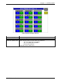
IP-EMZ
Service Manual
COUNTRY: CAN. USA. EU.
IMPORTANT
• Read this manual thoroughly, and do not perform
installation, operation, maintenance, or inspection
unless you fully understand all of the contents.
• Keep this manual in a safe place where you can refer
to it easily while installing, operating, and carrying out
maintenance or inspections.
PN 107287
© ISHIDA Co., Ltd. 2008
All rights are reserved. No part of this publication may be reproduced, stored in a retrieval system, or
transmitted in any form or by any means mechanical, electronic, photocopying, recording, or otherwise
without prior written permission of ISHIDA. The information contained in this manual is subject to change
without notice.
IMPORTANT NOTICE
This manual explains the procedures to perform installation, operation, service, or maintenance of the
machine.
Those who handle the machine must be aware of the hazards involved. These dangers may not be obvious,
so it is imperative to follow the instructions detailed in this manual when installing, operating, inspecting, or
servicing the machine. Therefore, we recommend that you thoroughly read and understand this manual
before installing, operating, inspecting, or servicing the machine, and keep this manual in a safe place
where you can refer to it whenever necessary.
ISHIDA is not liable for any damage, loss or injury that results from incorrect operation, insufficient caution,
unauthorized modifications to the machine, or failure to follow the instructions contained in this manual.
In the recent weighing industry, the latent hazards involved with handling the machine have increased due
to new materials, new processing methods, and higher processing speeds, and it is impossible to predict all
of the possible dangers.
Likewise, there are far too many operations which cannot or should not be performed to fully describe all of
them in the manual. Please assume that any handling or operation not specifically described in this manual
should never be performed.
Safety countermeasures should be carefully considered and implemented before performing any
installation, operation, inspection, or maintenance procedure not specifically described in this manual or
indicated on the machine itself.
CHANGE IN SPECIFICATIONS
Machine specifications and accessories may be changed at any time due to improvements or other
reasons. Consult with your ISHIDA representative at any time to confirm the actual specifications of the
purchased machine.
ERRORS AND OMISSIONS
The information in this manual has been carefully checked and is believed to be accurate. However, please
understand that the descriptions in this manual may not agree with the actual machine due to machine
improvements. The information is subject to change without prior notice in the future. ISHIDA assumes no
responsibility for clerical, typographical or proofreading errors, or omissions.
LIMITATIONS OF LIABILITY
ISHIDA assumes no responsibility for special, indirect, or consequential damages, loss of profits or
commercial loss in any way connected with the machine, whether such claim is based on contract, warranty,
negligence, or strict liability.
ISHIDA shall assume responsibility for problems with the machine or the system based on an individual
maintenance contract. However, ISHIDA shall not be responsible for secondary problems.
ISHIDA assumes no responsibility for the user's programming of this machine, or any consequence thereof.
In no event shall ISHIDA be responsible for warranty, repair, or other claims regarding the machine unless
ISHIDA’s analysis confirms that the machines were properly handled, stored, installed, and maintained and
not subject to contamination, abuse, misuse, or inappropriate modification or repair.
IP-EMZ Service Manual
i
PRECAUTION SYMBOLS
This machine is manufactured for use according to proper procedures by a qualified operator and only for
the purposes described in this manual.
Warning symbols in this manual are divided into three categories, depending on the level of danger, or
seriousness of potential injury. The definition of each of these warnings and precautions is shown below.
Failure to heed these warnings or precautions may result in bodily injury or damage to the machine.
Indicates information that, if not heeded, is likely to result in loss of life or serious
injury.
Indicates information that, if not heeded, could possibly result in loss of life or serious
injury.
Indicates information that, if not heeded, could result in relatively serious or minor
injury, damage to the machine, or faulty operation.
SAFETY CONSIDERATIONS
This service manual contains information necessary for servicing the machine. To ensure the safety and
long operating life of this machine, it is important to observe the following precautions:
• Servicing is to be done by qualified service personnel only
These service instructions are for use by qualified service personnel who fully understand the potential
hazards involved. To avoid any possible danger, do not perform any service procedures unless qualified
to do so.
• Perform only the specified service procedures
To ensure personal safety, do not perform any service procedures that are not specifically mentioned in
this manual.
• Avoid servicing while power is being supplied
The power supply to the machine is disconnected only when the electrical plug is removed from the
electrical outlet. For protection against electrical shock, remove the plug before performing any servicing
to the machine. Servicing the machine while power is being supplied and opening or removing covers or
enclosures should be avoided as much as possible. When servicing cannot be performed by any other
means, service personnel should take precautions against the danger of electrical shock or other
potential hazards involved.
• Take precaution against residual electrical charge hazard
Capacitors inside the machine may still hold an electrical charge even after power is disconnected.
• Use the same type of fuses and components for replacement parts
To avoid the potential hazards involved, do not replace fuses or components with types other than those
specified in the parts list for this machine.
ii
IP-EMZ Service Manual
TABLE OF CONTENTS
Chapter 1
INSTALLATION
1.1
SPECIFICATIONS ............................................................................ 1-2
1.2
NAME OF EACH PART .................................................................... 1-4
1.2.1 FRONT VIEW............................................................................. 1-4
1.2.2 REAR VIEW ............................................................................... 1-4
1.3
OUTER DIMENSIONS ..................................................................... 1-5
1.4
PREPARATION FOR INSATALLATION............................................ 1-6
1.4.1 UNPACKING .............................................................................. 1-6
1.4.2 THINGS TO BE PREPARED ..................................................... 1-6
1.5
PRECAUTIONS FOR INSTALLATION ............................................. 1-7
1.5.1 GENERAL PRECAUTIONS ....................................................... 1-7
1.5.2 MAINTENANCE PRECAUTIONS .............................................. 1-7
1.5.3 PROHIBITED LOCATIONS ........................................................ 1-7
1.5.4 PRECAUTIONS FOR POWER SUPPLY ................................... 1-7
1.6
HARDWARE INSTALLATION ........................................................... 1-8
1.7
FINALIZING INSTALLATION .......................................................... 1-10
Chapter 2
SETUP MODE
2.1
SETUP MENU ENTRY ..................................................................... 2-2
2.2
SETUP MENU .................................................................................. 2-3
2.3
EXPIRY DATE SETTING.................................................................. 2-5
2.4
PASSWORD SETTING .................................................................... 2-8
2.5
WORDWRAP WIDTH SETTING ...................................................... 2-9
2.6
REFERENCE DATA SETUP........................................................... 2-10
2.7
TOTAL ADD SETTING ................................................................... 2-12
2.8
BARCODE SETUP ......................................................................... 2-14
2.9
ITEM CODE SETTING ................................................................... 2-16
2.10 PLU DEFAULT DATA SETTING ..................................................... 2-17
2.11 PLU UPDATE SETTING ................................................................. 2-19
2.12 KEY LOCK SETTING ..................................................................... 2-21
2.13 PLU DATE/TIME SETTING ............................................................ 2-24
2.14 PLU OPERATION SETTING .......................................................... 2-25
IP-EMZ Service Manual
iii
2.15 ERROR SETTING .......................................................................... 2-26
2.16 PRINT SELECT SETTING ............................................................. 2-27
Chapter 3
TEST MODE
3.1
TEST MENU ENTRY ........................................................................ 3-2
3.2
TEST MENU ..................................................................................... 3-3
3.3
KEY CHECK MENU ......................................................................... 3-4
3.3.1 STROKE KEY CHECK ............................................................... 3-5
3.3.2 TOUCH PANEL ADJUSTMENT ................................................. 3-6
3.4
MACHINE SET 1/2: BASIC COMPONENT ...................................... 3-7
3.4.1 MACHINE SET 1/2 (COMPONENT) .......................................... 3-7
3.4.2 MACHINE SET 2/2 (VARIATION)............................................... 3-8
3.5
SELF DIAGNOSTIC ......................................................................... 3-9
3.6
MEMORY INITIALIZATION ............................................................ 3-10
3.7
DISPLAY ADJUSTMENT ................................................................ 3-11
3.8
SCALE CALIBRATION ................................................................... 3-12
3.8.1 A/D DATA INITILAIZATION, ZERO POINT/SPAN
ADJUSTMENT ......................................................................... 3-12
3.8.2 SCALE ADJUSTMENT ............................................................ 3-14
3.9
PRINT ADJUSTMENT 1/2: PRINTER HEAD ................................. 3-15
3.9.1 PRINT ADJUSTMENT 1/2........................................................ 3-15
3.9.2 PRINT ADJUSTMENT 2/2........................................................ 3-22
3.10 ROM VERSION DISPLAY .............................................................. 3-25
3.11 COMMUNICATION CHECK ........................................................... 3-26
3.12 OPTION CHECK ............................................................................ 3-27
3.13 MEMORY DATA CHANGE MENU .................................................. 3-28
3.13.1 SRAM DATA CHANGE............................................................. 3-29
3.13.2 FROM DATA REFERENCE...................................................... 3-30
3.14 TIME AND DATE SETTING ............................................................ 3-31
Chapter 4
iv
SYSTEM MODE
4.1
SYSTEM MENU ENTRY .................................................................. 4-2
4.2
SYSTEM MENU ............................................................................... 4-3
4.3
TCP/IP SETUP ................................................................................. 4-5
4.4
SYSTEM DATA SETUP .................................................................... 4-7
4.5
AUTO PROGRAM SETTING............................................................ 4-9
4.5.1 AUTOMATIC UPDATE ITEMS ................................................. 4-11
4.6
LABEL PRINT COMBINATION SETUP .......................................... 4-12
4.6.1 CONNECTED PRINTER / PATTERN SELECTION ITEMS ..... 4-18
4.6.2 LABEL DETAIL SETUP ............................................................ 4-19
4.7
FORMAT SETTING ........................................................................ 4-22
4.8
PRINT ITEM SETTING ................................................................... 4-23
IP-EMZ Service Manual
4.9
FILE CHECK .................................................................................. 4-25
4.10 FILE INPUT/OUTPUT .................................................................... 4-27
4.11 FREE MESSAGE NAME REGISTRATION .................................... 4-30
4.12 LINK MASTER ERROR SETUP ..................................................... 4-31
4.13 DISPLAY ERROR LOG .................................................................. 4-32
4.13.1 ERROR LOG FILE OUTPUT PROCEDURE............................ 4-34
4.13.2 ERROR LOG FILE OUTPUT DELETE PROCEDURE ............. 4-35
4.14 SRAM DATA INPUT/OUTPUT ........................................................ 4-36
4.15 FILE TRANSFER MENU ................................................................ 4-42
4.15.1 OPTION DEVICE PROGRAM FILE COPY .............................. 4-43
4.15.2 IMAGE FILE COPY .................................................................. 4-44
4.16
MEAT CUT SETUP ........................................................................ 4-46
4.17
TRACEABILITY SETUP ................................................................. 4-48
4.18
SPECIAL TIME ............................................................................... 4-49
4.19
CF FILE I/O .................................................................................... 4-51
4.19.1 FILE DOWNLOAD ................................................................... 4-51
4.19.2 FILE UPLOAD .......................................................................... 4-54
4.12.3 FILE DELETION....................................................................... 4-57
4.20
MACHINE NO. ............................................................................... 4-59
4.21
EXCHANGE RATE ......................................................................... 4-60
4.22
SCANNER SETUP ......................................................................... 4-61
Chapter 5
MECHANICAL ASSEMBLY
5.1
CASSETTE UNIT ............................................................................. 5-2
5.2
MAIN BODY UNIT ............................................................................ 5-4
5.3
DISPLAY UNIT ................................................................................. 5-6
5.4
SCALE UNIT .................................................................................... 5-7
Chapter 6
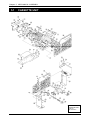
ELECTRIC ASSEMBLY
6.1
ELECTRIC BLOCK DIAGRAM ......................................................... 6-2
6.2
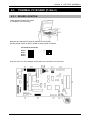
MAIN PC BOARD (P-910R-2) .......................................................... 6-3
6.2.1 BOARD LOCATION ................................................................... 6-3
6.2.2 I/O SIGNALS .............................................................................. 6-4
6.3
THERMAL PC BOARD (P-964-3)..................................................... 6-7
6.3.1 BOARD LOCATION ................................................................... 6-7
6.3.2 I/O SIGNALS .............................................................................. 6-8
6.4
CONTROL CONSOLE PC BOARD (P-917B-2) ............................. 6-10
6.4.1 BOARD LOCATION ................................................................. 6-10
6.4.2 I/O SIGNALS ............................................................................ 6-11
6.5
CONNECTOR JUNCTION PC BOARD (P-918A-1) ....................... 6-12
6.5.1 BOARD LOCATION ................................................................. 6-12
6.5.2 I/O SIGNALS ............................................................................ 6-12
IP-EMZ Service Manual
v
6.6
LAN PC BOARD (P-967-1) ............................................................. 6-14
6.6.1 BOARD LOCATION ................................................................. 6-14
6.6.2 I/O SIGNALS ............................................................................ 6-14
6.7
DISPLAY JUNCTION PC BOARD (P-919B-3) ............................... 6-15
6.7.1 BOARD LOCATION ................................................................. 6-15
6.7.2 I/O SIGNALS ............................................................................ 6-15
6.8
SCALE BOARD (P-930A-1/2) ........................................................ 6-17
6.8.1 BOARD LOCATION ................................................................. 6-17
6.8.2 DIP SWITCH SETTING ........................................................... 6-17
6.8.3 I/O SIGNALS ............................................................................ 6-18
6.9
SWITCHING POWER SUPPLY (2H113WI) ................................... 6-19
6.9.1 BOARD LOCATION ................................................................. 6-19
6.9.2 I/O SIGNALS ............................................................................ 6-20
APPENDIX A LABEL FORMATTING
vi
A.1
LABEL FORMAT TABLE .................................................................. A-2
A.2
LABEL FORMAT TABLE CONFIGURATION ................................... A-3
A.3
PRINTING POSITION CHANGE ...................................................... A-4
A.4
PRINT SIZE CHANGE ..................................................................... A-5
A.5
FIXED CHARACTER CONTENT CHANGE ..................................... A-6
IP-EMZ Service Manual
Chapter 1 INSTALLATION
1
INSTALLATION
Contents
1.1
1.2
1.3
1.4
1.5
1.6
1.7
SPECIFICATIONS ............................................................. 2
NAME OF EACH PART ....................................................... 4
OUTER DIMENSIONS ........................................................ 5
PREPARATION FOR INSTALLATION ................................. 6
PRECAUTIONS FOR INSTALLATION ................................ 7
HARDWARE INSTALLATION .............................................. 8
FINALIZING INSTALLATION ............................................. 10
IP-EMZ Service Manual
1-1
Chapter 1
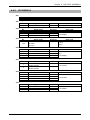
1.1
No.
1
1.1
1.2
2
2.1
2.2
3
3.1
3.2
4
INSTALLATION
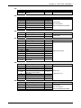
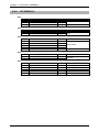
SPECIFICATIONS
Item
Operating environment
Temperature range
Operating humidity
Outer dimensions
Main body
Scale unit
Mass
Main body
Scale unit
Power supply
5 Weighing capacity
6 Weighing accuracy
7 Display unit
8
9
10
11
12
12-1
12-2
12-3
13
13-1
13-2
14
14-1
14-2
15
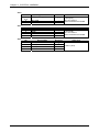
Printing method
Thermal head
Print speed
Effective print size
Label size
Label width
Label length
Backing paper width
Label diameter
Core inner diameter
Max. outer diameter
Keys
Touch panel
Stroke key
I/O
16
16-1
16-2
17
Program storage medium
Flash ROM (1MB)
Compact Flash (32MB)
Memory capacity
17-1
17-2
17-3
17-4
17-5
17-6
17-7
17-8
17-9
17-10
PLU master
Additive master
POP master
Comment master
Origin master
Storage temperature master
Storage method master
Free master 1
Free master 2
Free master 3
1-2
Specifications
-5°C - 40°C (23°F – 104°F)
20% - 85% (Non condensing)
W285 × D368 × H645mm (11.2 × 14.5 × 25.4)
W300 × D270 × H88mm (11.8 × 10.6 × 3.5)
19kg (41.8 lbs)
6kg (13.2 lbs)
CAN, USA:
AC110-120V 50/60Hz 4A
EU:
AC230V 50/60Hz 4A
CAN:
6kg/15kg
Graduation: 0.002kg (0 –6kg),0.00 5kg (6- 15kg)
15lb/30lb
Graduation: 0.005lb (0 – 15lb),0.01lb (15 – 30lb)
USA:
15lb/30lb
Graduation: 0.005lb (0 – 15lb),0.01lb (15 – 30lb)
EU:
3kg/6kg
Graduation: 0.001kg (0 –3kg),0.00 2kg (3- 6kg)
1/3000
10.4-inch TFT color liquid crystal VGA with backlight
(640 × 480 dots)
Direct thermal method
LH4114K (TDK) 3-inch (640 dots), 8 dots/mm
100mm/sec
78mm
30 - 80mm
30 - 150mm
32 - 82mm
φ 76mm
φ 2240mm
212mm × 159mm
24 keys
Ethernet:1ch
RS-232C:2ch
PCMCIA:2ch
I2NET:2ch(ISHIDA Original Protocol)
Boot program
OS + Application program
*The registration number varies depending on the total memory
capacity.
511 characters, 4,000 PLUs, 5 prices
511 characters, 9,999 additives
39 characters, 999 POPs
511 characters, 99 comments
39 characters, 9,999 origins
119 characters, 99 temperatures
119 characters, 99 methods
511 characters, 99 messages
511 characters, 99 messages
511 characters, 99 messages
IP-EMZ Service Manual
Chapter 1 INSTALLATION
No.
17-11
17-12
17-13
17-14
17-15
17-16
17-17
17-18
17-19
Item
Free master 4
Free master 5
Format master
Label master
Department name master
Group name master
Class name master
Sales promotion master
Store master
17-20
17-21
17-22
18
19
Tray master
Memo preset keys
Classification preset keys
Barcode print
POS code system
20 POS types
21 Durability
21-1 Number of label issues
21-2 Printer frame drawer
21-3 Display angle adjustment
frequency
21-4 Volume adjustment
frequency
21-5 LCD backlight
21-6 Power switch
IP-EMZ Service Manual
Specifications
511 characters, 99 messages
511 characters, 99 messages
99 characters, 2,048 bytes/format
99 labels
13 characters, 9,999 names
13 characters, 9,999 names
13 characters, 9,999 names
99 images, 99 comments, 999 origins
9,999 stores,
48 characters/store name, 48 characters/store address
9,999 trays, 10 characters/tray
56 items (28 items x 2 pages)
36 types (5 ranges/type)
NON-PLU 13 digits, NON-PLU 8 digits
PLU 13 digits, PLU 8 digits
5-digit standard code, 6-digit code including check price,
6-digit code including flag, 5-digit code including check price,
6-digit code + 5-digit price
16.2 million labels.(label length 42mm, 9,000 labels,
360 operation days, 5 years, 721km)
7,300 times (4 times/day, 360 days × 5 years)
3,650 times (2 times/day, 360 days × 5 years)
7,300 times (4 times/day, 360 days × 5 years)
40,000 hours (10.9 years on the assumption of 10 hours/day)
10,000 times, 6.8 years on the assumption of 4 times/day
1-3
Chapter 1
INSTALLATION
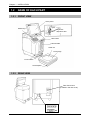
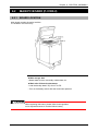
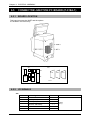
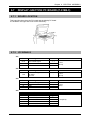
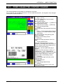
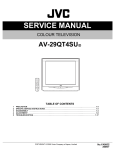
1.2
NAME OF EACH PART
1.2.1
FRONT VIEW
Touch panel
Lighter
Stroke keys
Darker
Brightness
adjustment dial
Label outlet
Label cassette
Scale unit
Level gauge
Power switch
Level adjuster
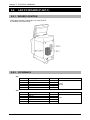
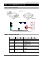
1.2.2
REAR VIEW
Rear Connectors
(Located in the rear cover)
1-4
IP-EMZ Service Manual
Chapter 1 INSTALLATION
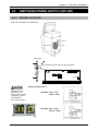
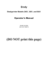
1.3
OUTER DIMENSIONS
(Unit: mm)
IP-EMZ Service Manual
1-5
Chapter 1
INSTALLATION
1.4
PREPARATION FOR INSATALLATION
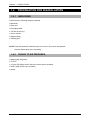
1.4.1
UNPACKING
Confirm that the following things are packed.
• Main body
• Scale unit
• Grounding cable
• Tool Screw driver(+)
• User’s manual
• Weight (500g)
• Cleaning pen
NOTE: Parts are fixed with adhesive tapes so as not to move when transported.
Remove these tapes when unpacking.
1.4.2
THINGS TO BE PREPARED
• Weight (6kg,15kg,30lb)
• IF-21FD
• 3.5-inch 2DD floppy disk in which the user's data is recorded
• I2NET cable (D-sub 9 pin -modular)
• Labels
1-6
IP-EMZ Service Manual
Chapter 1 INSTALLATION
1.5
PRECAUTIONS FOR INSTALLATION
1.5.1
GENERAL PRECAUTIONS
z DO NOT PUT HANDS IN THE MACHINE
When you need to put your hand inside the machine, always push the Emergency Stop Button first.
Never put your hand inside the machine.
z ALWAYS KEEP HANDS AWAY FROM THE MOVING PARTS
When the power is turned ON, some parts may still move after a commodity or tray has been called,
and your hand may get caught in the machine.
z DO NOT PUT YOUR HAND INSIDE THE POWER SUPPLY UNIT
There is danger of electric shock if you touch the inside of the Power Supply Unit. Never touch
directly or spill water into the unit. Also, never touch the Main Power Switch with wet hands.
z DO NOT DISASSEMBLE OR MAKE ANY ALTERATIONS TO THE MACHINE
The machine can be damaged if disassembled incorrectly. Making any alterations without
permission, or removing any parts other than those specified, may cause a serious accident or
injury.
z HANDLE WITH CARE AS THIS IS A PRECISION MACHINE
Bumps or shocks to the machine can cause damage.
1.5.2
MAINTENANCE PRECAUTIONS
• Keep the area around the machine clear of any dust and debris.
• Do not leave screws or other foreign objects in the machine after performing routine maintenance
since this can cause major damage to the machine when the electrical switch is turned on.
• Always remove wires by holding the connector and pulling to disconnect.
Do not disconnect by pulling on the wires themselves since this may cause a wire to snap or
damage the connection.
• Before disassembling or adjusting this machine, make sure you thoroughly understand and follow
each step in the order indicated in this manual.
1.5.3
PROHIBITED LOCATIONS
Do not install the machine in the following types of places:
•
•
•
•
•
•
•
•
Places subject to high temperatures or high humidity
Places exposed to direct sunlight
Places where water or other liquids are easily spilled on the machine
Places subject to excessive vibration or unstable foundations
Places exposed to direct cold air from air conditioners or refrigerators
Places where the floor or foundation is unstable
Places subject to a lot of dust or dirt
Places with large voltage fluctuations
1.5.4
PRECAUTIONS FOR POWER SUPPLY
Do not use an unspecified power supply.
• Use a power supply with rated voltage ground.
• Prepare a dedicated power source.
A power supply that generates voltage variation may cause a malfunction.
• To avoid any potential electrical shock, securely attach the ground wire to the grounding provision.
IP-EMZ Service Manual
1-7
Chapter 1
1.6
INSTALLATION
HARDWARE INSTALLATION
1.
Install the main body to be able to see
the display clearly and perform the key
operation easily.
2.
Connect the cable of the scale unit with
the main body.
Connection or separation in the
power-on state may cause damage.
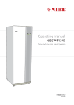
3.
Turn the level adjuster so that the unit
is horizontally installed. To install the
scale unit horizontally, turn the level
adjuster until the bubble locates at the
center of circle of the level gauge.
Scale unit
Bubble
Level gauge
Circle
If this adjustment is not performed
accurately, a weighing error may occur.
Level adjuster
4.
Make sure that the machine is
grounded at the power supply outlet.
5.
Insert the power plug into the outlet.
(CAN,USA)
(EU)
1-8
IP-EMZ Service Manual
Chapter 1 INSTALLATION
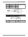
7.
When connecting other devices, connect them according to the following.
Other machine of the master/satellite system I2NET (INLINE) (Dsub 9 pin)
Optional printer······················································ I2NET (OPTION1) (Modular jack)
IF-21FD ································································· I2NET (INLINE) (Dsub 9 pin)
Journal printer ······················································· RS-232C
8.
Fix the harnesses.
NOTE:
Nylon clamps to fix harnesses are not
attached. Prepare the nylon clamps
beforehand with their sizes according to
the number of the connected harnesses.
Fig.1 Rear Connectors
(Located in the rear cover)
9.
Load labels to be used by the user. Refer to “Label Replacement” in the User’s Manual.
IP-EMZ Service Manual
1-9
Chapter 1
1.7
INSTALLATION
FINALIZING INSTALLATION
Weighing check
Span check
6kg:
Place the 6kg weight on the weighing platter and confirm that the displayed weight is within ±1d (2g).
15kg:
Place the 15kg weight on the weighing platter and confirm that the displayed weight is within ±1d (5g).
30lb:
Place the 30lb weight on the weighing platter and confirm that the displayed weight is within ±1d
(0.01lb).
Four corner check
6kg:
Place weights (Approximately 3kg but not heavier) on the center and four corners of the weighing
platter, and confirm that the difference between the center and four corners is within ±1d (1g).
15kg:
Place weights (Approximately 6kg but not heavier) on the center and four corners of the weighing
platter, and confirm that the difference between the center and four corners is within ±1d (2g).
30lb:
Place weights (Approximately 15lb but not heavier) on the center and four corners of the weighing
platter, and confirm that the difference between the center and four corners is within ±1d (0.005lb).
Operation check
Call up a product, place a load on the weighing platter, and issue a label.
After issuing the label, clear the result.
Set content save
Connect the IF-21FD and save the settings.
Operation explanation
Explain the operation method and precautions to the user.
1-10
IP-EMZ Service Manual
Chapter 2 SETUP MODE
2
SETUP MODE
Contents
2.1
2.2
2.3
2.4
2.5
2.6
2.7
2.8
2.9
2.10
2.11
2.12
2.13
2.14
2.15
2.16
2.17
IP-EMZ
SETUP MENU ENTRY .............................................................. 2
SETUP MENU ........................................................................... 3
EXPIRY DATE SETTING........................................................... 5
PASSWORD SETTING ............................................................. 8
WORDWRAP WIDTH SETTING ............................................... 9
REFERENCE DATA SETUP ..................................................... 10
TOTAL ADD SETTING .............................................................. 12
TIMER SET ............................................................................... 14
BARCODE SETUP .................................................................... 15
ITEM CODE SETTING .............................................................. 17
PLU DEFAULT DATA SETTING ................................................ 18
PLU UPDATE SETTING............................................................ 20
KEY LOCK SETTING ................................................................ 22
PLU DATE/TIME SETTING ....................................................... 25
PLU OPERATION SETTING ..................................................... 26
ERROR SETTING ..................................................................... 27
PRINT SELECT SETTING ........................................................ 28
Service Manual
2-1
Chapter 2 SETUP MODE
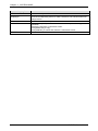
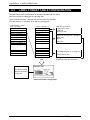
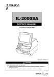
2.1
SETUP MENU ENTRY
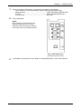
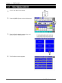
1.
Turn on the Main Power Switch.
2.
Press the [MENU] button on the initial screen.
3.
Press the [SETUP] button to display the Setup
Menu screen.
4.
The Setup Menu screen appears.
2-2
IP-EMZ
Service Manual
Chapter 2 SETUP MODE
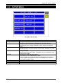
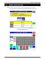
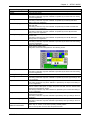
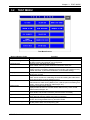
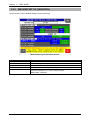
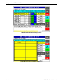
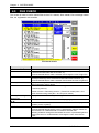
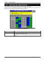
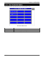
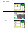
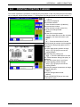
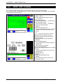
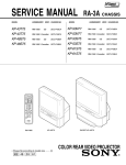
2.2
SETUP MENU
Setup Menu Screen (1/2)
Buttons/Display Fields
Expiry Date Set
Password Set
Word-wrap Set
Reference Data Set
Total Set
TIMER Set (Only EU )
MENU
PAGE
IP-EMZ
Service Manual
Function
Changes to the Expiry Date Setting screen.
Set the expiry text change days, cutoff date text, and pack date text.
Changes to the Password Setting screen.
Set the password for entering Registration, Setup, Total, and Subtraction
modes.
Changes to the Word-wrap Width Setting screen.
Set the text width in 0.1mm increments for PLU name, Message, etc. for an
automatic linefeed.
Changes to the Reference Data Setup screen.
Specify the operation when “Refer” is selected in the PLU registration, and
set the reference data.
Changes to the Total Add Setting screen.
Set whether or not to add the data to totals.
Set a maximum of 20 target commodities to be added to hourly totals.
Set the weight data type (fixed weight, actual weight) when a fixed price
commodity is added to totals.
Changes to the first screen of the Setup Menu.
Turns over the screen.
2-3
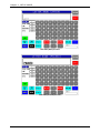
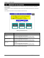
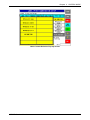
Chapter 2 SETUP MODE
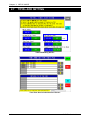
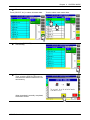
Ä
Setup Menu Screen (2/2)
Buttons/Display Fields
Barcode Setup
Item Code Set
PLU Defaults
PLU Update
Key Lock Setup
PLU Date/Time
PLU Operation
Error Setup
Print Select
MENU
PAGE
2-4
Function
Changes to the Barcode Setting screen.
Set the POS type, POS system, and POS flag (system reference data).
Changes to the Item Code Setting screen.
Assign the classification code (position/digit number) in an item code, and set
the code position and the digit number for a barcode.
Changes to the PLU Default Data Setting screen display.
Set the default master data when newly created in the PLU registration.
Changes to the PLU Update screen.
Perform the batch data changing process for the master data of existing
commodities.
Changes to the Key Lock Setup screen.
Set the key lock password, and the key lock availability for each item.
Changes to the PLU Date/Time Setting screen.
Set the pack date holding function, accrued pack date processing, and time
rounding.
Changes to PLU Operation Setting screen.
Set the number of digits for calling a PLU code, register code, wrapping
mode, unit price holding function, and shop change processing.
Changes to the Error Setup screen.
Set the processing procedure when a PLU code is not found, the price data is
“0”, a PLU in which the tare weight is not registered is called, or the head
failure is detected.
Changes to the Print Select screen.
Set whether to print the barcode on the top of the tray when two labels are
issued, and the barcode is set to print on the bottom label.
It is referred when “System Reference” is set in the barcode print selection
when two labels are issued in the store master registration.
Changes to the first screen of the Setup Menu.
Turns over the screen.
IP-EMZ
Service Manual
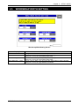
Chapter 2 SETUP MODE
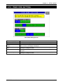
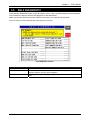
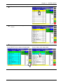
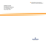
2.3
EXPIRY DATE SETTING
Note: This function does not use, In the case of 6 or more characters of the date title.
The title of the date is using the [UNIT TYPE =FIXED Character] of a label format.
Expiry Date Setting Screen
Text Edit (Before) Screen
IP-EMZ
Service Manual
2-5
Chapter 2 SETUP MODE
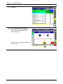
Text Edit (After) Screen
Text Edit (Packed) Screen
2-6
IP-EMZ
Service Manual
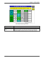
Chapter 2 SETUP MODE
Buttons/Display Fields
MENU
Switch Days
Before Switch
After Switch
Pack Date
IP-EMZ
Service Manual
Function
Changes to the first screen of the Setup Menu.
Press the [SET] button after numeric entry (0-99) to set the entered data as
switching days.
When the expiry date is same as or before the “Switch Days”, the text in the
“Before Switch” field is printed.
When “0” is set in this field, switching does not happen and the text in the
“Before Switch” field is printed.
Selects “Before Switch” field and the field color changes yellow.
Press the [EDIT] button to display the text edit screen.
Up to 6 characters can be registered.
Selects “After Switch” field and the field color changes yellow.
Press the [EDIT] button to display the text edit screen.
Up to 6 characters can be registered.
Selects “Pack Date” field and the field color changes yellow.
Press the [EDIT] button to display the text edit screen.
Up to 6 characters can be registered.
2-7
Chapter 2 SETUP MODE
2.4
PASSWORD SETTING
Password Setting Screen
Buttons/Display field
MENU
Password
Mode Selection Buttons
Function
Changes to the first screen of the Setup Menu.
Set the password data by pressing this button after 6-gigit numeric entry.
Press this button after “000000” entry to cancel the password and the mode
selection.
Only one password can be registered.
Press the desired button(s) to select the mode that requires the password
entry. The selected mode button becomes blue.
When you have forgotten the password.
2-8
IP-EMZ
Service Manual
Chapter 2 SETUP MODE
2.5
WORDWRAP WIDTH SETTING
Word-wrap Width Setting Screen
Buttons/Display Fields
MENU
PLU Name
Function
Changes to the first screen of the Setup Menu.
Enter a numeric value (1-9999) and press the [SET] button to set the entered
value (unit: 0.1mm) as a word-wrap width value.
Extra Message 1,2 Width Enter a numeric value (1-9999) and press the [SET] button to set the entered
value (unit: 0.1mm) as a word-wrap width value.
Extra Message 1,2 Pitch Enter a numeric value (1-99) and press the [SET] button to set the entered
value (unit: 0.1mm) as a gap between characters.
IP-EMZ
Service Manual
2-9
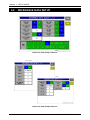
Chapter 2 SETUP MODE
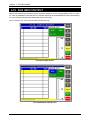
2.6
REFERENCE DATA SETUP
Reference Data Setup 1/2 Screen
[ CAN, USA ]
[ EU ]
Reference Data Setup 2/2 Screen
2-10
IP-EMZ
Service Manual
Chapter 2 SETUP MODE
Buttons/Display Fields
MENU
PAGE
Pack Date Print
Sell By Date Print
Shelf Life (days)
Use By Date Print
Use By Date (days)
Pack Time Print
Pack Time Flag
Sell By Time Print
Sell By Time Flag
Unit Type
Open Price Select
Standard Tare
Logo #1, #2, #3
Safe Handling image No.
USE BY DATE
PRINT/TYP/& DATE
IP-EMZ
Service Manual
Function
Determines the settings and returns to the first screen of the Setup Menu.
Turns over the screen.
Press “YES” or “NO” to set whether to print the Pack Date or not.
This setting is effective only when “REFER” is specified by the Pack Date Print setting
in the PLU registration.
Press “YES” or “NO” to set whether to print the Sell By Date or not.
This setting is effective only when “REFER” is specified by the Sell By Date Print
setting in the PLU registration.
Enter a numeric value (0-9999) and press this field to set the entered value as the
Shelf Life data.
This setting is effective only when “REFER” is specified by the Shelf Life Date Print
setting in the PLU registration.
Press “YES” or “NO” to set whether to print the Use By Date or not.
This setting is effective only when “REFER” is specified by the Use By Date Print
setting in the PLU registration.
Enter a numeric value (0-9999) and press this field to set the entered value as the Use
By Date data.
This setting is effective only when “REFER” is specified by the Use By Date print
setting in the PLU registration.
Press “YES” or “NO” to set whether to print the Pack Time or not.
This setting is effective only when “REFER” is specified by the Pack Time Print setting
in the PLU registration.
Specify the pack time to be used.
Clock: Use the system clock.
Designated: Use the time designated on the following screen.
Press “YES” or “NO” to set whether to print the Pack Time or not.
This setting is effective only when “REFER” is specified by the Pack Time Print setting
in the PLU registration.
Not used
Set the unit type of quantity data for fixed price items.
This setting is effective only when “REFER” is specified by the Unit Type setting in the
PLU registration.
Select whether or not to allow price change in Normal Mode.
This setting is effective only when “REFER” is specified by the Open Price setting in
the PLU registration.
Set the standard tray weight.
Enter a numeric value (max. 3 digits) and press this field, then the entered data
becomes the standard tray weight.
This setting is effective only when “REFER” is specified by the Forced Tare setting in
the PLU registration.
Enter a numeric value (max. 3 digits) and press this field, then the entered data
becomes the logo data.
This setting is effective only when “REFER” is specified by the Logo setting in the PLU
registration.
Enter a numeric value (max. 3 digits) and press this field.
This setting is effective only when “REFER” is specified by the Logo setting in the PLU
registration.
Press “YES” or “NO” to set whether to print the title “USE By DATE” or not.
Select "day" or "month", in the case of printing "USE By DATE".
Enter a “Use By Date” numeric value and press this field.
2-11
Chapter 2 SETUP MODE
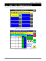
2.7
TOTAL ADD SETTING
USA
Total Add Setting Screen
Time Zone Set for Individual PLU Screen
2-12
IP-EMZ
Service Manual
Chapter 2 SETUP MODE
Buttons/Display Fields
MENU
Daily Total
Function
Determines the settings and returns to the first screen of the Setup Menu.
Select whether or not to add the data to Daily Total.
The selected button color will change to blue.
This is not displayed at a satellite machine in master/satellite specification.
Accumulative Total
Select whether or not to add the data to Accumulative Total.
The selected button color will change to blue.
This is not displayed at a satellite machine in master/satellite specification.
Periodical Total
Select whether or not to add the data to Periodical Total.
The selected button color will change to blue.
This is not displayed at a satellite machine in master/satellite specification.
Time Zone Total
Select whether or not to add the data to Time Zone Total.
The selected button color will change to blue.
This is not displayed at a satellite machine in master/satellite specification.
Daily Total Auto Clear
Select whether or not to clear Daily Total when turning off the machine.
The selected button color will change to blue.
This is not displayed at a satellite machine in master/satellite specification.
Tray Total
Select whether or not to add the data to Tray Total.
The selected button color will change to blue.
This is not displayed at a satellite machine in master/satellite specification.
Fixed Price PLU Weight Select to add either “Fixed Weight” or “Real Weight” for a fixed price item to
Addition Mode
total.
The selected button color will change to blue.
ITEM SPECIFY
Displays the Time Zone Set For Individual PLU screen.
CONFIRM
Determines the settings and returns to the Total Add Setting Screen.
Clears the existing Daily PLU Time Zone Total.
CANCEL
Cancels the settings and returns to the Total Add Setting Screen.
ADD
Add a commodity to target commodities by pressing this button after selecting
the desired PLU or entering the PLU number.
DELETE
Delete a commodity from target commodities by pressing this button after
selecting the PLU to be deleted.
IP-EMZ
Service Manual
2-13
Chapter 2 SETUP MODE
2.8
TIMER SET
Only EU specifications
The seal heater of Wrap-mini-EMZ is controlled. IP-EMZ does not function.
Timer Set Screen
2-14
IP-EMZ
Service Manual
Chapter 2 SETUP MODE
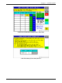
2.9
BARCODE SETUP
After this, it is SETUP MENU 2/2.
[9][9][9] > [PAGE]
Barcode Setup Screen
Buttons/Display Fields
MENU
Non PLU 13
Non PLU 8
PLU 13
PLU 8
POS Code Type
IP-EMZ
Service Manual
Function
Determines the settings and returns to the first screen of the Setup Menu.
This is referred when “System” is set in the flag reference of the PLU
registration and the code type is set as “Non PLU 13”.
The set flag data is displayed.
Enter a numeric value (max. 2 digits) and press the [SET] button to set the
entered data as a flag data.
This is referred when “System” is set in the flag reference of the PLU
registration and the code type is set as “Non PLU 8”.
The set flag data is displayed.
Enter a numeric value (max. 2 digits) and press the [SET] button to set the
entered data as a flag data.
This is referred when “System” is set in the flag reference of the PLU
registration and the code type is set as “PLU 13”.
The set flag data is displayed.
Enter a numeric value (max. 2 digits) and press the [SET] button to set the
entered data as a flag data.
This is referred when “System” is set in the flag reference of the PLU
registration and the code type is set as “PLU 8”.
The set flag data is displayed.
Enter a numeric value (max. 2 digits) and press the [SET] button to set the
entered data as a flag data.
Select the code type to be referred to when the code type is set as “Refer” in
the PLU master file.
Press the desired button to select among Non PLU 13, Non PLU 8, PLU 13,
and PLU 8.
2-15
Chapter 2 SETUP MODE
Buttons/Display Fields
POS Code Kind
2-16
Function
Select the code kind to be referred to when the code kind is set as “Refer” in
the PLU master file.
Press the desired field to select among 31 different kinds.
IP-EMZ
Service Manual
Chapter 2 SETUP MODE
2.10 ITEM CODE SETTING
Item Code Setting Screen
Buttons/Display Fields
MENU
Code Digit Display
Classification Code
Select
Classification Code Digit
Set
JAN Code Select
JAN Code Digit Set
IP-EMZ
Service Manual
Function
Determines the settings and returns to the first screen of the Setup Menu.
The set digit(s) is displayed.
Select one of code types “Department Code” “Group Code” and “Section
Code” of which code digit(s) is displayed.
Set the code digit position (max. 4 digits) for the selected code type by
pressing the contiguous fields.
Select one of code types “JAN 8” and “JAN 13” of which code digit(s) is
displayed.
Set the code digit position (max. 8 digits) for the selected code type by
pressing the contiguous fields.
2-17
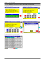
Chapter 2 SETUP MODE
2.11 PLU DEFAULT DATA SETTING
PLU Default Data Setting 1 Screen
PLU Default Data Setting 2 Screen
2-18
IP-EMZ
Service Manual
Chapter 2 SETUP MODE
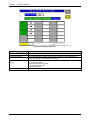
PLU Default Data Setting 3 Screen
Buttons/Display Fields
MENU
PAGE
Default Data Setting
Items
IP-EMZ
Service Manual
Function
Determines the settings and returns to the first screen of the Setup Menu.
Turns over the screen.
Each button color has its meaning:
z BackgroundGreen: Unit price master data, Blue: PLU master data
z CharactersBlack: Requires numeric entry, White: Make a selection
2-19
Chapter 2 SETUP MODE
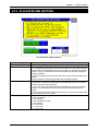
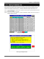
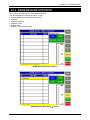
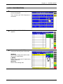
2.12 PLU UPDATE SETTING
PLU Update Screen
Buttons/Display Fields
MENU
S T
S T
S T
SELECT
SELECT EXECUTE
FULL EXECUTE
Unit Price No.
Item Name
Before
After
PLU No. Range
2-20
Function
Determines the settings and returns to the first screen of the Setup Menu.
Changes to the previous or next screen.
Moves the cursor up or down.
Selection can be made for items to be collectively changed.
Master data at the cursor position is selected.
When selected, “z” is displayed in the selected filed at the cursor position on
the list.
Selection cannot be made when no data is set in “After” field.
Executes changes in “After” field for the selected items only to the PLU
master file of which “Before” data matches.
Executes changes in “After” field for the selected items only to all PLU master
files.
Select the desired unit price master file among “1” through “5”.
The name of master item to be collectively changed is displayed. (See the
master name list below)
Data can be set in this field when pressed after numeric entry.
Selection items appear when pressed without numeric entry.
Data can be set in this field when pressed after numeric entry.
Selection items appear when pressed without numeric entry.
Specifies the PLU range to be collectively changed.
IP-EMZ
Service Manual
Chapter 2 SETUP MODE
Master Name
Before / After Data Range
Default Value
Sales Mode
Unit Price
Fixed Price
Markdown Price Mode
Markdown Price
Fixed Weight
Pack Quantity
Tare
Pack Data Print
Sell-By Data Print
Shelf Life Time
Use-By Print
Use-By (day)
Barcode Type
POS Flag
Weigh / Non-Weigh / Weigh & Fixed Price
0.00 - 999.99
0.00 - 999.99
Refer to “PLU Data Registration” in Programming Mode.
Depending on “Markdown Price Mode”
0.000 - 99.999
0 - 999
0.000 - 5.998
Refer / Yes / No
Refer / Yes / No
1 day - 9999 day(s)
Refer / Yes / No
0 day(s)
Refer / Non-PLU 13 / Non-PLU 8 / PLU 13/ PLU 8
00 - 99
Weigh
0.00
None
Normal
0.00
0.000
0
0.000
Refer
Refer
1 day(s)
Refer
0 day(s)
Refer
02
POS Code
0000000000 - 9999999999
0000000000
Open Price
Forced Tare
Extra Message 1
Refer / Prohibit / Allow
Refer / Yes / No
0 - 999999
Refer
Refer
0
Extra Message 2
Extra Message 3
Pack Time Print
Pack Time Mode
Pack Time Data
Sell-By Time Print
Sell-By Time Mode
Use-By Time
Free 1 No.
Free 2 No
Free 3 No
Free 4 No
Free 5 No
POP No.
Coupon Message
0 - 999999
0 - 999999
Refer / Yes / No
Refer / Designate / Clock
0:00 - 23:59
Refer / Yes / No
Refer / Relative
0 hour(s) - 9999 hour(s)
0 - 999999
0 - 999999
0 - 999999
0 - 999999
0 - 999999
0 - 999
0 - 999999
0
0
Refer
Refer
0:00
Refer
Refer
0 hour
0
0
0
0
0
0
0
Image 1 No.
Image 2 No.
Image 3 No.
Label Format
Second Label
0 - 999
0 - 999
0 - 999
0 - 999
Yes / No
0
0
0
0
YES
Second Label Format
0 - 99
0
Item Code
Unit Type
Upper Weight Limit
Lower Weight Limit
Tray No.
Wrapping Mode
00000000 - 99999999
Refer to “PLU Data Registration” in Programming Mode.
0.000 - 99.999
0.000 - 99.999
0 - 9999
Wrap & Label / Label / Wrap
00000000
Refer
0.000
0.000
0
Wrap & Label
Infeed Speed
High Speed / Medium Speed / Low Speed
High Speed
Wrapping Speed
Tray Refer / High Speed / Medium Speed / Low Speed
Tray Refer
Label Rotation
Tray Volume
Auto Detection
Labeling Mode
Normal Label / Horizontal Label / Vertical Label
No Volume / Low Volume / Medium Volume / High Volume
Auto Tray / Tray Designate
Auto Label / Manual Label
Normal Label
No Volume
Auto Tray
Auto Label
IP-EMZ
Service Manual
2-21
Chapter 2 SETUP MODE
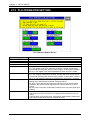
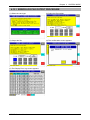
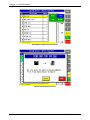
2.13 KEY LOCK SETTING
Key Lock Setting 1/5 Screen
Key Lock Setting 2/5 Screen
2-22
IP-EMZ
Service Manual
Chapter 2 SETUP MODE
Key Lock Setting 3/5 Screen
Key Lock Setting 4/5 Screen
IP-EMZ
Service Manual
2-23
Chapter 2 SETUP MODE
Key Lock Setting 5/5 Screen
Buttons/Display Fields
MENU
PAGE
Unlock Password
Key Lock Objective
Group
Key Lock Items
2-24
Function
Determines the settings and returns to the first screen of the Setup Menu.
Turns over the screens.
Press this filed after numeric entry (4 numeric digits) to set a password to
make “Key Unlock” of a function key effective.
Select one of the following key groups:
y Function key group
y Numeric function key group
y Touch panel key group
y Stroke key group
Select “Yes” to lock the key, or “None” not to lock the key.
IP-EMZ
Service Manual
Chapter 2 SETUP MODE
2.14 PLU DATE/TIME SETTING
PLU Date/Time Setting Screen
Buttons/Display Fields
MENU
Pack Date Hold
Accrued Pack Date
Time Rounding
IP-EMZ
Service Manual
Function
Determines the settings and returns to the first screen of the Setup Menu.
Select one of the following items:
y Fix: Pack date and time which have been set after the power was turned on
will be held until the power will be turned on again, or data will be changed.
When “+1 Day” is selected in the Accrued Pack Date, the date changes to
holding condition.
y By PLU: Pack date and time at the time of PLU call is held until next PLU is
called.
y Real: Pack date and time are printed when the label is printed.
Select one of the following items:
y No process: Temporary change data is canceled when next PLU is called
and becomes the date of that day.
y +1 day: The pack date will become the date added by one day to that day.
When “Fix” is selected in the Pack Date Hold, this selection cannot be
made.
y Hold: Data that has been changed temporarily as an accrued pack date will
be held until next PLU is called.
Select one of the following items:
y 0: 00 minute fixed
y 1: No rounding
y 2: Touch panel key group
y 5: 05 minutes
y 10: 10 minutes
y 15: 15 minutes
y 30: 30 minutes
2-25
Chapter 2 SETUP MODE
2.15 PLU OPERATION SETTING
PLU Operation Setting Screen
Buttons/Display Fields
MENU
PLU Digit
Store Selection
Unit Price Selection
Register Code Hold
Function
Determines the settings and returns to the first screen of the Setup Menu.
Select the number of digits (4/6/8) when calling a PLU.
Select whether or not to call a store in the normal mode.
Select whether or not to fix the Unit Price No. that is set to the called store.
Select one of the following items to hold the register code:
y Fix: The register code which has been set after the power was turned on
will be held until the power will be turned on again, or data will be changed.
y By PLU: The register code will be updated every time the PLU is called.
Wrapping Mode Hold
Select one of the following items to hold the wrapping mode:
y Fix: The wrapping mode which has been set after the power was turned on
will be held until the power will be turned on again, or data will be changed.
y By PLU: The wrapping mode will be updated every time the PLU is called.
Printer Change Selection When the machine is set as “Store change available”, select one of the
following items to determine the printer changing method:
y By Store: This is effective only when the machine is set as “Store change
available”, the printer number registered in the store master file is given
priority.
y By Eye-catch: The printer is selected according to the eye-catch (label print
pattern).
Unit Price Call Selection Perform the holding selection for the Unit Price No. in the normal mode.
y Unit Price No.1: The Unit Price No.1 is always selected when any PLU is
called.
y Last Unit Price: The Unit Price No. which was processed last is memorized,
and it will be called when the PLU is called next time.
2-26
IP-EMZ
Service Manual
Chapter 2 SETUP MODE
2.16 ERROR SETTING
Error Setting Screen
Buttons/Display Fields
MENU
No POS Code Set Error
Price 0 Error
Thermal Head Cut Error
Display
No Tare Weight Error
No Tray Wrapping Set
Error
IP-EMZ
Service Manual
Function
Determines the settings and returns to the first screen of the Setup Menu.
Select one of the following items to determine the procedure when calling a
PLU of which POS code is not set.
y Non Error: No error screen appears.
y Non Print: An error screen appears. When the error screen is released,
calling the PLU will be canceled.
y Non Barcode: An error screen appears. When the error screen is released,
the barcode will be blanked on the label.
Select whether or not to display an error screen when “0” price is entered.
Select one of the following items to determine the procedure when a head
failure occurs.
y Consistent: An error screen always appears once a failure occurs.
y Line Cut: An error screen appears when a failure occurs.
y None: No error screen appears.
Select whether or not to display an error screen when printing is performed
without tare weight setting.
Select one of the following items to determine the procedure when no tray
wrapping is set.
y Non Error: No error screen appears even when the tray wrapping image is
not set.
y Non Print: Even after the error screen is released, it appears every time
until the tray wrapping image is normally set. Operation is prohibited when
the tray wrapping image is not set.
y Non Image: An error screen appears when the tray wrapping image is not
set. After the error screen is released, it will not appear until next call.
2-27
Chapter 2 SETUP MODE
2.17 PRINT SELECT SETTING
Buttons/Display Fields
MENU
Front Label Barcode
Print Selection
Function
Returns to the first screen of the Setup Menu.
This function is effective only when two labels are issued, and the bottom
label type is selected to print the barcode. Select whether or not to print the
barcode on the first label. (See the table below)
Select one of the following items to determine an expansion error procedure.
y Error: Output the expansion error, and stop processing.
y Max. Print: Expand to a maximum and print within the range.
Item Name Over Print
Selection
When front label barcode is printed
(PLU master file)
When front label barcode is not printed
(PLU master file)
Front Label Barcode Print Selection
Bottom Label
Type
Print
Front
Front Label Barcode Print Selection
Bottom Label
Type
No print
Print
No print
Bottom
Front
Bottom
Front
Bottom
Front
None
{
-
{
-
None
²
-
²
-
Barcode
{
{
²
{
Barcode
²
{
²
{
Additive
Barcode +
Additive
Collective
display
Collective
display +
Barcode
Collective import
Collective import
+ Barcode
{
²
{
²
²
²
²
²
{
{
²
{
²
{
²
{
{
-
{
-
²
-
²
-
{
{
²
{
²
{
²
{
{
-
{
-
²
-
²
-
{
{
²
{
Additive
Barcode +
Additive
Collective
display
Collective
display +
Barcode
Collective import
Collective import
+ Barcode
²
{
²
{
{: With barcode print
2-28
Bottom
²: Without barcode print
IP-EMZ
Service Manual
Chapter 2 SETUP MODE
IP-EMZ
Service Manual
2-29
Chapter 3
TEST MODE
3
TEST MODE
Contents
3.1
3.2
3.3
3.4
3.5
3.6
3.7
3.8
3.9
3.10
3.11
3.12
3.13
3.14
IP-EMZ
TEST MENU ENTRY ................................................................... 2
TEST MENU ................................................................................ 3
KEY CHECK MENU .................................................................... 4
MACHINE SET 1/2: BASIC COMPONENT ................................. 7
SELF DIAGNOSTIC .................................................................... 9
MEMORY INITIALIZATION ......................................................... 10
DISPLAY ADJUSTMENT ............................................................. 11
SCALE CALIBRATION ................................................................ 12
PRINT ADJUSTMENT ................................................................. 15
ROM VERSION DISPLAY ......................................................... 25
COMMUNICATION CHECK ...................................................... 26
OPTION CHECK ....................................................................... 27
MEMORY DATA CHANGE MENU ............................................. 28
TIME AND DATE SETTING ....................................................... 31
Service Manual
3-1
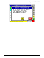
Chapter
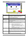
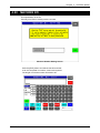
3.1
3 TEST MODE
TEST MENU ENTRY
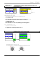
1.
Turn on the Main Power Switch.
2.
Press the [MENU] button on the initial screen.
3.
Enter “495344” using the numeric keys and
press the [TEST MODE] button.
4.
The Test Menu screen appears.
3-2
IP-EMZ
Service Manual
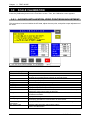
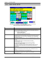
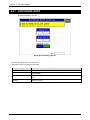
Chapter 3
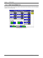
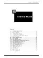
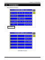
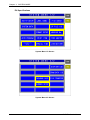
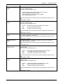
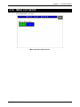
3.2
TEST MODE
TEST MENU
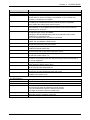
Test Menu Screen
Buttons/Display Fields
Key Check
Machine Setting
Self-diagnostic
Memory initialization
Display check
Calibration
Print adjustment
ROM version
Communication check
Option check
Memory data change
Time/ Date setting
IP-EMZ
Service Manual
Function
Changes to the Key Check menu screen.
Changes to the Machine Setting screen.
Set basic machine and optional unit configuration.
Changes to the Self-diagnostic screen.
Check cables, memory, printer head and connection check, etc.
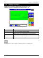
Changes to the Memory Initialization screen.
Display memory information (installed and remainder) and initialize memory
(master data clear, system data initialization, and test data setting).
Changes to the Display Check screen.
Adjust color contrast.
Changes to the Scale Calibration screen.
There are two screens for calibrating the scale and setting the scale board.
(Scale board setting requires password entry)
There are two screens for adjusting the printer head information (head type,
head resistance, head running distance, etc.) and the print information (print
density, various sensor distances, label length, etc.).
Changes to ROM version display.
Displays ROM versions for OS, BSP, BIOS, Main memory, Scale, ELAN,
Thermal head, Wrapper, etc.
Changes to the Communication Check screen.
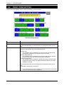
Check I2NET and RS232C hardware (Communication and RAM).
Changes to the Option Check screen.
Check barcode scanner reading and card slot operation.
Changes to the Memory Data Change menu screen.
Confirm and change SRAM memory and refer FROM.
Changes to date and time setup screen.
Set the present date, time, and printing year.
3-3
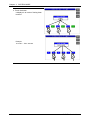
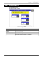
Chapter
3.3
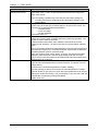
3 TEST MODE
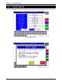
KEY CHECK MENU
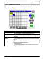
Press the [Key Check] button on the Test Menu screen. Then, the Key Check Menu screen appears.
Key Check Menu Screen
Buttons/Display Fields
MENU
Numeric Key Check
Touch Panel Adjustment
3-4
Function
Returns to the Test Menu 1/2 screen.
Changes to the Numeric Key Check screen.
Press the stroke keys on the keypad, then the corresponding button will
change its color black on the screen.
Changes to the Touch Panel Adjustment screen.
Adjust touch panel press position by pressing the center marks (+) on the
two buttons located at the top left and the bottom right of the screen using
a pointed object, and finally pressing the center mark (+) on the
acknowledge button.
IP-EMZ
Service Manual
Chapter 3
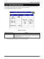
3.3.1
TEST MODE
STROKE KEY CHECK
Press the [Numeric Key Check] button on the Key Check Menu screen. Then, the Numeric Key Check
screen appears. Stroke keys can be tested by pressing each key on the control console. Pressing
each numeric key will temporarily change the corresponding button color to black. After checking all
stroke keys, press the [MENU] button to return to the Key Check Menu screen.
Numeric Key Check Screen
Buttons/Display Fields
MENU
IP-EMZ
Service Manual
Function
Changes to the Key Check Menu screen.
3-5
Chapter
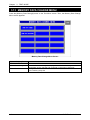
3.3.2
3 TEST MODE
TOUCH PANEL ADJUSTMENT
Press the [Touch Panel Adjustment] button on the Key Check Menu screen. Then, the Touch Panel
Adjustment screen appears. Screen and touch panel positions on the LCD screen can be adjusted on
this screen.
Press the two center marks on each button located at the top left and the bottom right of the screen
using a pointed object. The pressed button will change its color to black, and the coordinates
positional data of the pressed point is displayed.
In the same way, press the center mark on the Acknowledge button to complete the position
adjustment.
Press the MENU button to return to the Key Check Menu screen.
Note 1: Be sure to adjust the touch panel after system data has been initialized.
2: If the adjustment cannot be properly completed, enter “999” and press the [PLU] key to return to
the default data, then, tray to perform adjustment again.
Touch Panel Adjustment Screen
Buttons/Display Fields
MENU
Position Adjustment [+]
Acknowledge [+]
Coordinate Display Field
3-6
Function
Changes to the Key Check Menu screen.
Press only the “+” mark on the buttons located at the top left and the bottom
right of the screen.
Pressing these buttons will change the button color to black.
Completes position adjustment.
Displays coordinate information.
IP-EMZ
Service Manual
Chapter 3
3.4
TEST MODE
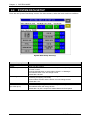
MACHINE SET 1/2: BASIC COMPONENT
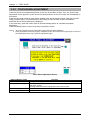
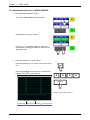
Press the [Machine Setting] button on the Test Menu screen. Then, the Machine Set 1/2 (Component)
screen appears.
3.4.1
MACHINE SET 1/2 (COMPONENT)
This procedure is used to determine which program is to be used with this machine.
Press one of the buttons based on the actual machine configuration. When selected, the button color
will reverse yellow
Machine Set 1/2 (Component) Screen
Buttons/Display field
DP Type
IP-EMZ
Service Manual
Function
Used when no wrapping unit is equipped.
3-7
Chapter
3.4.2
3 TEST MODE
MACHINE SET 2/2 (VARIATION)
On this screen, further detailed settings can be performed.
Machine Setting 2/2 (Variation) Screen
Buttons/Display Fields
MENU
CANCEL
Wrapper Setup Item
Printer Setup Item
Printer No.1
3-8
Function
Returns to Test Menu 1/2 screen.
Cancels changes and returns to Machine Set 1/2 screen.
Not used.
Displays connection results with various printers and the applicator.
Selects printer #1.
Press the “Standard” or “2 colors” button to select.
Default data: “Standard”
IP-EMZ
Service Manual
Chapter 3
3.5
TEST MODE
SELF DIAGNOSTIC
Press the [Self Diagnostic] button on the Test Menu screen. Then, the Self Diagnostic screen appears.
This procedure is used to perform self-diagnosis for the listed items.
Make sure that the I2Net connecters, RS232C connectors, and card slot are provided.
Note: All memory will be initialized after executing this procedure.
Self-diagnostic Screen
Buttons/Display Fields
MENU
EXECUTE
Execution Item
IP-EMZ
Service Manual
Function
Returns to the Test Menu 1/2 screen.
Press the [EXECUTE] button to execute cable, memory, printer head,
display operation checks, and initialization.
Displays execution results (Operating/Normal/Abnormal) to the right of each
item.
3-9
Chapter
3 TEST MODE
3.6
MEMORY INITIALIZATION
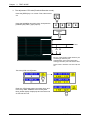
Press the [Memory Initialization] button on the Test Menu screen. Then, the Memory Initialization
screen appears.
This procedure is used to delete all data except system data, initialize system data only, and create
test data.
Note: Repeat the procedure if memory initialization ends abnormally.
Memory Initialization Screen
Buttons/Display Fields
MENU
Master Data
CLEAR
System Data
INITIALIZATION
Test Data
SETTING
Function
Returns to the Test Menu 1/2 screen.
Clear master data.
“Processing” is displayed during execution.
“Normal” is displayed when the execution has ended normally.
“Abnormal” is displayed when execution has ended abnormally.
Initialize system data (system master and machine master data).
“Processing” is displayed during execution.
“Normal” is displayed when the execution has ended normally.
“Abnormal” is displayed when execution has ended abnormally.
Set test data after master data has been cleared and system data has been
initialized.
“Processing” is displayed during execution.
“Normal” is displayed when the execution has ended normally.
“Abnormal” is displayed when execution has ended abnormally.
Note: Repeat the procedure if memory initialization ends abnormally.
3-10
IP-EMZ
Service Manual
Chapter 3
3.7
TEST MODE
DISPLAY ADJUSTMENT
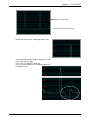
Press the [Display Check] button on the Test Menu screen. Then, the display check screen appears.
This procedure is used to check whether the screen shows an ideal color contrast or not. To adjust the
color contrast, turn the knob on right side of the operating console.
Display Adjustment Screen (Vertical)
Display Adjustment Screen (Horizontal)
Buttons/Display Fields
MENU
Horizontal/Vertical
Function
Returns to the Test Menu 1/2 screen.
Changes between horizontal and vertical color patterns.
Turn the knob on right side of the operating console to adjust color contrast.
IP-EMZ
Service Manual
3-11
Chapter
3 TEST MODE
3.8
SCALE CALIBRATION
Press the [Calibration] button on the Test Menu screen. Then, the Calibration screen appears.
3.8.1
A/D DATA INITILAIZATION, ZERO POINT/SPAN ADJUSTMENT
This procedure is used to initialize the A/D data, adjust the zero point, and perform span adjustment of
the scale.
Calibration Screen
Buttons/Display Fields
MENU
PAGE
ZERO
SPAN
[+][-]
INITIALIZE
Capacity
A/D Value
Span Value
Weight
Voltage
Stability Signal
Scale Setting
Information
DIP Switch Data
3-12
Function
Returns to the Test Menu 1/2 screen.
Changes to the scale adjustment screen after password has been entered.
Inputting the command sends it directly to the scale board.
Executes zero point adjustment.
Executes span adjustment.
Executes fine span adjustment using these buttons.
Executes the scale board initialization.
Displays weighing capacity in “kg” based on scale board information.
Displays A/D (read) data (count value) in A/D units.
Subtracts span data from the read data (the above mentioned A/D value) and
displays the value (count value) in A/D units.
Displays the weight value in “kg” calculated form the A/D value based on the
set district information.
Displays the voltage.
“Normal” is displayed when the first stability signal is received normally.
The display goes blank if communication is unsuccessful.
Displays basic performance data and country specific scale setting data.
Displays scale board DIP switch setting status.
Refer to the table below.
IP-EMZ
Service Manual
Chapter 3
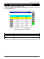
TEST MODE
DIP Switch Settings
DIP SW bit
0
1
2
3
4
5
6
7
Content
Board No.
0: Set with “X” command
1: “0” fixed
Storage command
0: “W” command prohibited
1: “W” command allowed
Test mode
0: “∗” command prohibited
1: “∗” command allowed
Movement average
0: 8 times
1: None
Zero bias
0: Yes
1: No
Sending weight
0: No
1: 20msec
A/D data
0: ASC-HEX 5byte
1: ASC-HEX 6byte
Analog filter
0: Software
1: Hardware
Memory Switch
Please push a Memory switch after the completion of adjustment.
IP-EMZ
Service Manual
3-13
Chapter
3 TEST MODE
3.8.2
SCALE ADJUSTMENT
This procedure is used to select the weighing capacity and create a command message to be sent to
the scale.
Enter “495344” using the numeric keys and press the [PAGE] button.
Ä
This window is different at types of
SCALE. Or it does not display.
Scale Adjustment Screen
Buttons/Display Fields
BACK
Capacity
SPAN
Select
[ABC] [abc]
SEND
Send Data
Receive Data
3-14
Function
Returns to the Calibration screen.
Select either “6kg” or “15kg”.
Press the button that corresponds to the capacity to be selected. The button
color will change to blue.
Executes span adjustment.
Select either “ABC” or “abc”.
These buttons select upper or lowercase letters for alphabetic input when
creating a command message to send to the scale board.
Select letter type by pressing the corresponding button. The button color will
change to blue.
Send the command message to the scale unit.
Displays command message data sent to the scale board.
Displays command message data received from the scale board.
IP-EMZ
Service Manual
Chapter 3
3.9
TEST MODE
PRINT ADJUSTMENT
Press the [Print Adjustment] button on the Test Menu screen. Then, the Print Adjustment 1/2 screen
appears.
3.9.1
PRINT ADJUSTMENT 1/2
This procedure is used to set various printing conditions, and adjust various sensor levels for the
selected printer.
Print Adjustment 1/2 Screen
Buttons/Display Fields
MENU
PAGE
DPM (Digital
Potentiometer)
Printer No.
Label No.
IP-EMZ
Service Manual
Function
Returns to Test Menu 1/2 screen.
Changes to Print Adjustment 2/2 screen.
Adjust the sensitivity of each label sensor and peel sensor.
Changes the label and peel sensor value Display Fields to green and makes
it possible to change data. Adjust sensitivity by pressing one of the sensor
value Display Fields and making a numeric entry.
Sensitivity can be adjusted by pressing one of sensor value Display Fields
after numeric entry.
Touch this button again to exit sensitivity adjustment mode and return the
color to white.
Displays the printer number to be adjusted.
Touch the [SET] button after numeric entry to set a new printer to be adjusted.
Data range is 1-4.
Displays the label number that is linked with the numbers of the printer and
the cassette to be adjusted.
Set the label number in the label detail screen in System Mode.
Default data: “1” for printer #1, “2” for printer #2, “6” for PP printer.
Set the above-mentioned label sensor threshold (standard) value for each
label number.
3-15
Chapter
3 TEST MODE
Buttons/Display Fields
Head Resistance
Head Error Check
Memory Initialization
Head Type
Function
Displays thermal head resistance (Ω, zero suppression).
Touch the [SET] button after numeric entry to set new head resistance.
Data range is 0-999.
The buzzer will sound if data is set beyond the specified range.
Touch the [SET] button without numeric entry to automatically set head
resistance.
“Auto Setting” is displayed during the execution of automatic settings.
Execute thermal head error check.
“Processing” is displayed during processing.
“Normal” is displayed when processing has ended normally.
“Abnormal” is displayed when processing has ended abnormally.
Initialize printer memory.
“Processing” is displayed during processing.
“Normal” is displayed when processing has ended normally.
“Abnormal” is displayed when processing has ended abnormally.
Execute sensor levels, back feed calibration, initialization of the protection
setting value against head temperature rise, and acquisition of the head
resistance, and initialization of label and cassette master data for the selected
printer.
Be sure to execute this procedure when the P-910 has been replaced.
Displays thermal head type name.
One of the following three types can be set:
Press the [SET] button after numeric entry to set the desired head type.
Default data: “0” LH4114 (8 dots/mm standard).
1: LH4116 (8 dots/mm history control). Printing is not possible with the
LH4116 head (8 dots/mm history control) installed. Printing can be
normally performed when “1” is set and the LH4114 installed.
Usage Distance
Cassette Status
Head Up Sensor
Label Sensor Level
Peel Sensor Level
3-16
2: BHP4312 Set the BHP4312 (8 dots/mm 2 colors) when using two color
specifications. Set the DIP switch on the thermal board and "Thermal
paper type" in “Print Adjustment 2/2” screen to “2: 2 color label”.
Thermal head movement distance (“km”, zero suppression) is displayed.
Touch the [SET] button to clear head movement distance.
Refer only when adjusting the cassette applicable printer.
{{{{: No cassettes are inserted.
{{{z: Cassette 1 is inserted.
The same sensor as [Head Up Sensor] is used.
Displays head status.
“ON” is illuminated when the head is set normally.
“OFF” is illuminated when the head is up.
Displays label sensor level.
Touch this button to finely adjust the label sensor level (display field will
change to green) and press the (UV) adjustment buttons. Touch this button
again to change the display to white and set adjustment data. The level range
is 0-255.
Displays peel sensor level.
Touch this button to finely adjust the peel sensor level (display field will
change to green) and press the (UV) adjustment buttons. Touch this button
again to change the display to white and set adjustment data. The level range
is 0-255.
IP-EMZ
Service Manual
Chapter 3
STANDARD VALUE
TEST MODE
STANDARD VALUE can perform change of the threshold value of label
sensor and peel sensor.
Default: 0
Default: 90
LABEL SENSOR STD VALUE
The initial value of the threshold value of a label sensor is 0.
Level Detection mode:
0 STD judges the difference of the Sensor output level, of label and label gap.
In the case of 60 or more, a level difference judges it as a label gap.
Threshold Detection mode:
In the case of one (1) or more, STD considers it as the value of threshold.
If the value of threshold is exceeded, it will be judged as a label gap.
PEEL SENSOR STD VALUE
Only Threshold Detection mode:
It is judged that the value below threshold has a label.
It is judged that the value exceeding threshold has no label.
DPM
DIGITAL POTENTIAL METER
Digital The position of volume can be checked.
It is a minimum 0 from a maximum 255.
The following figure is a case where it transposed to analog type volume.
IP-EMZ
Service Manual
3-17
Chapter
3 TEST MODE
The adjustment method of a LABEL SENSOR
1. The adjustment method of a gain.
Touch the [LABEL SENSOR LEVEL] button.
Display field will change to green.
Touch the (UV) adjustment buttons. Press this
button again to change the display to white and set
adjustment data.
2. The check method of a sensor level.
Press the [FEED] key 2 or 3 times. Then, label comes
out.
FEED
Press the [2][0][0][0] at numeric keys. And press the
[PRESET] key. Then, graph pops up.
2
0
0
0
PRESET
Graph in case a STD value is 0
Label gap
3-18
Label
IP-EMZ
Service Manual
Chapter 3
TEST MODE
Red Line is STD value.
Graph in case a STD value is XXX.
Please adjust the output of label gap to 200 - 240.
Label which has shade in graphic design may cause
60 or more output change.
In this case, it is judged as label gap.
In such a case ,Please set it as Threshold Detection
mode(STD value).
IP-EMZ
Service Manual
3-19
Chapter
3 TEST MODE
3. The adjustment STD value(Threshold Detection mode)
Press the [FEED] key 2 or 3 times. Then, label comes
out.
FEED
Press the [2][0][0][0] at numeric keys. And press the
[PRESET] key. Then, graph pops up.
2
0
0
0
PRESET
STD Preset value
A
2/3
1/2
A is the value between label detection part
and label gap detection part.
Label detection part is the highest value.
Label gap detection part is the lowest value.
Preset value is between one half of A, and
2/3.
Touch the [STD VALUE] button.
Enter the “STD Preset value” at numeric keys, and
touch the [LABEL SENSOR STD VALUE] field.
Next, please display Graph pops and check the line
of STD VALUE Line.
3-20
IP-EMZ
Service Manual
Chapter 3
TEST MODE
The adjustment method of a PEEL SENSOR
1. The adjustment method of a gain.
Check the value of PEEL SENSOR LEVEL. When not
covered by label between Peel sensor.
With a value 200 or more , it is good.
With 200 or less , adjust [PEEL SENSOR LEVEL].
If a level does not go up, the optic axis has shifted. Or
Sensor is no good.( Adjustment method the optic
axis. or Exchange sensors.)
Touch the [FEED] key . Then, label comes out.
When covered by label between Peel sensor.
Check PEEL SENSOR LEVEL in this state.
10 or less are normal.
When much more values are shown, the influence
from a spotlight may be received.
In this case, please avoid a light source.
2. The adjustment STD value
Touch the [STD VALUE] button.
The check of PEEL SENSOR LEBEL can also be
performed in this mode.
Enter the “STD value” at numeric keys. And touch the
[PEEL SENSOR STD VALUE].
IP-EMZ
Service Manual
3-21
Chapter
3.9.2
3 TEST MODE
PRINT ADJUSTMENT 2/2
This procedure is used to set printing conditions, label and peel sensor distances, and various labeling
conditions for test label printing.
Print Adjustment 2/2 Screen
3-22
IP-EMZ
Service Manual
Chapter 3
Buttons/Display Fields
MENU
PAGE
Printer No.
Print Density
Print Speed
Test Format No.
Label Sensor Distance
Peel Sensor Distance
Test Label Length
Label Gap
Feed
Feed (Stop)
Test Print
(Label Print)
IP-EMZ
Service Manual
TEST MODE
Function
Returns to the Test Menu 1/2 screen.
Changes to the print adjustment (head information) screen.
Displays the number of the printer to be adjusted.
Press the [SET] button after a numeric entry to change the number of the
printer to be adjusted.
The data range is 1-4. The buzzer will sound if data is entered outside the
range or no data is entered.
Displays the set print density. Press the [SET] button after a numeric entry to
set the print density. The data ranges from 0 (lightest) to 9 (darkest), and the
buzzer will sound if data is entered outside the range or no data is entered.
The default value is “5”.
Displays the set print speed (mm/sec). Press the [SET] button after a numeric
entry to set the print speed.
The data range is 60-130 (in units of 10mm/sec.).
The default value is “100mm/sec.”.
A slower print speed results in a higher print quality.
Displays the test label format number (2 digits) to be referred to for test
printing or label feeding. Press this button after a numeric entry to set the
label format for the test print. The data range is 1-99, and the buzzer will
sound if data is entered outside the range or no data is entered. The default
value is the default format set in the printer.
Displays the set label sensor distance (mm). The entered data can be set as
the printer label sensor distance by pressing the [SET] button after a numeric
entry. The data range is 1-999 in increments of 0.1mm. The default value is
41.0mm.
Displays the set peel sensor distance (mm). The entered data can be set as a
peel sensor distance of the objective printer by pressing the [SET] button after
a numeric entry. The data range is 1-999 in increments of 0.1mm. The default
value is 11.0mm.
Displays label length (mm) for test printing. The entered data can be set as
the printer label length by pressing the [SET] button after a numeric entry. The
data range is 1-9999 in increments of 0.1mm. A buzzer will sound if data is
entered outside the range or no data is entered. The default value is the label
length of the above-mentioned test format number. The label will be fed for
the distance of the label and gap lengths.
Displays the set gap length (mm). The entered data can be set as a gap
length of the printer by pressing the [SET] button after a numeric entry. The
data range is 1-999 in increments of 0.1mm. A buzzer will sound if data is
entered outside the range or no data is entered. The default value is 2.5mm.
Displays the set feed length (mm). The entered data can be set as the printer
feed length by pressing the [SET] button after a numeric entry. The data
range is 1-999 in increments of 0.1mm. The default value is 7.5mm. This data
becomes the back feed length when the back feed control is performed.
This is effective only when the automatic label applicator is used.
A label is issued leaving the set feed stop length, and fed for the length
immediately before it is sucked by the applicator. The set feed stop length is
displayed. Press the [SET] button after a numeric entry to set the feed stop
length of the printer. The data range is 1-999 in units of 0.1mm. The default
value is 3.5mm.
Select the print pattern when test printing is performed. Press either “Normal”
or “Checker” to select the item and change the button color to blue. When test
printing is performed, this selection information will be used. The default data
is “Checker”.
3-23
Chapter
3 TEST MODE
Buttons/Display Fields
Test Print
(Back Feed Control)
Paper Type
Back Feed Length
Heat Protection
Function
Select the back feed function when test printing is performed.
Press either “YES” or “NO” to select the desired function and change the
button color to blue.
Note: This setting is applied only to the test print. Back feed settings for
normal printing can be performed in the Label Detail Settings in the
System Menu.
Displays the type of thermal paper selected. Press the [SET] button after a
numeric entry to set the type of thermal paper to be used in the printer. The
data range is 0-9 with the following parameters:
1: Standard label
2: Two color label
3-9: Not registered
The default value is “1”.
A loss is caused in the feeding length for each roller due to the reverse
rotation of the motor, gears, and print roller during back feed operation. This
function is used to make up that loss.
It does not influence the store name, address, and ruled lines for each
existing format. However, it is used in the case of a format without sufficient
space.
The top and bottom dimensions (approximation) of the set label and the back
feed correction length (mm). Press the top/bottom select button to determine
the label top/bottom type for correction length.
Select one of three types: 45mm, 60mm, or 80mm. The selected size field
changes to blue. Press the correction length display field after a numeric
entry to set the correction length for the selected top and bottom dimensions.
The data range is 0.0-9.9mm.
Displays the heat protection selection for the set head. Press the [SELECT]
button to select head temperature increase protection. The button color will
change to blue.
No: Print even if the head temperature increases. (Default)
Yes: Stop printing for about 0.5 seconds if the head temperature increases.
The print density is high, and it is a level where the temperature over rises by
1000 piece continuous printing. The print density is high and the head will
overheat after continuously printing 1000 labels.
Usually set to “No”.
3-24
IP-EMZ
Service Manual
Chapter 3
TEST MODE
3.10 ROM VERSION DISPLAY
Press the [ROM Version] button on the Test Menu screen. Then, the ROM Version screen appears.
This procedure is used to display the ROM version of connected devices.
It cannot display devices that are not connected.
ROM Version Display
Buttons/Display Fields
MENU
Version Display
Function
Returns to the Test Menu 1/2 screen.
Displays the ROM version of connected devices.
The sample data for the above-mentioned display is different from actual
ROM version numbers.
Cannot display devices that are not connected.
The software of MAIN is Different at country and specifications.
IP-EMZ
Service Manual
3-25
Chapter
3 TEST MODE
3.11 COMMUNICATION CHECK
Press the [Communication Check] button on the Test Menu screen. Then, the Communication Check
screen appears. This procedure is used to perform various communication checks.
Communication Check Screen
Buttons/Display Fields
MENU
ELAN Loop Back
ELAN RAM
ELAN Cable
ILAN Loop Back
ILAN RAM
ILAN Cable
RS232C Dsub Cable
Display Status
3-26
Function
Returns to the Test Menu 1/2 screen.
Press the [EXECUTE] button to execute a send and receive loop test within
the board.
Press the [EXECUTE] button to execute a send and receive buffer memory
test.
Connect the IF-21FD to the cable to confirm the response.
Press the [EXECUTE] button to execute a cable test.
Press the [EXECUTE] button to execute a loop back test.
Press the [EXECUTE] button to execute an ILAN RAM test.
Connect the IF-21FD to the cable to confirm the response.
Press the [EXECUTE] button to execute a cable test.
Press the [EXECUTE] button to execute a cable test and RS-232C
input/output check.
Use the loop back connector for testing.
“Operating” is displayed during execution.
“Normal” is displayed when the execution has ended normally.
“Abnormal” is displayed when execution has ended abnormally.
IP-EMZ
Service Manual
Chapter 3
TEST MODE
3.12 OPTION CHECK
Press the [Option Check] button on the Test Menu screen. Then, the Option Check screen appears.
This procedure is used to perform scanner and card slot checks.
Option Check Screen
Buttons/Display Fields
MENU
Scanned Data
Slot 1 Check
Slot 2 Check
Display Status
IP-EMZ
Service Manual
Function
Returns to the Test Menu 1/2 screen.
Displays the OCR data when a barcode is read with the scanner.
Insert the formatted CF card (8M, 16M) and press the [EXECUTE] button to
execute an operation check.
Insert the formatted CF card (8M, 16M) and press the [EXECUTE] button to
execute an operation check.
“Operating” is displayed during execution.
“Normal” is displayed when the execution has ended normally.
“Abnormal” is displayed when execution has ended abnormally.
3-27
Chapter
3 TEST MODE
3.13 MEMORY DATA CHANGE MENU
Press the [Memory Data Change] button on the Test Menu screen. Then, the Memory Data Change
Menu screen appears.
Memory Data Change Menu Screen
Buttons/Display Fields
MENU
SRAM Data Change
FROM Data Reference
3-28
Function
Returns to the Test Menu 1/2 screen.
Press this button to change the display to the SRAM data change screen.
SRAM data can be changed and confirmed on the memory dump list.
Changes to the FROM data reference screen. FROM data can be confirmed
on the memory dump list.
IP-EMZ
Service Manual
Chapter 3
TEST MODE
3.13.1 SRAM DATA CHANGE
Press the [SRAM Data Change] button on the Memory Data Change Menu screen. Then, the SRAM
Data Change screen appears. This procedure is used to confirm or change SRAM data on the
memory dump list.
SRAM Data Change Screen
Buttons/Display Fields
MENU
SRAM Data Button
Display
Up/Down
Left/Right
SETTING
IP-EMZ
Service Manual
Function
Returns to the Memory data change menu screen.
Press any button (address position) to change its color to blue and enable
settings for modification. The memory data status is displayed.
Select either “HEX” or “ASC” data formats.
Press one of these buttons to select the data format and the selected button
will change to blue. The data display format will change in the SRAM data
display field.
Press these buttons to move active SRAM data (address) positions.
Press these buttons without a numeric entry to move the cursor in the desired
direction.
Press one of these buttons after a numeric entry to move the cursor to the
entered address position.
Press this button after numeric entry to set the entered data to the memory
data to be changed (RAM data field is blue).
The data range is 0-FF.
An operation error buzzer will sound if data is entered outside the range or
there is no numeric entry made.
3-29
Chapter
3 TEST MODE
3.13.2 FROM DATA REFERENCE
Press the [FROM Data Reference] button on the Memory Data Change Menu screen. Then, the
FROM Data Reference screen appears. This procedure is used to confirm FROM data on the memory
dump list.
FROM Data Reference Screen
Buttons/Display Fields
MENU
FROM Data Button
Display
Up/Down
Left/Right
SETTING
3-30
Function
Returns to the Memory data change menu screen.
Press any button to change its color to blue and display the set memory data.
Select either “HEX” or “ASC” data formats.
Press one of these buttons to select the data format and the selected button
will change to blue. The data display format will change in the FROM data
display field.
Press these buttons to move the displayed FROM data position.
Press these buttons without a numeric entry to move the cursor in the desired
direction.
Press one of these buttons after a numeric entry to move the cursor to the
entered address position.
This screen is used only for data reference and an error will occur if this
button is pressed.
IP-EMZ
Service Manual
Chapter 3
TEST MODE
3.14 TIME AND DATE SETTING
Press the [Time & Date Setting] button on the Test Menu screen. Then, the Time and Date Setting
screen appears. Enter the date (DD-MM-YYYY) and press the Date field to set. In the same manner,
enter the time (HH:MM:SS) and press the Time field to set.
Time and Date Setting Screen
Buttons/Display Fields
MENU
DATE
TIME
IP-EMZ
Service Manual
Function
Returns to the Test Menu 1/2 screen.
Press this button after a numeric entry to set the date.
Non-existent calendar dates cannot be set.
Data format is day (2 digits), month (2 digits), and year (4 digits).
Press this button after a numeric entry to set the time.
Data format is hour (2 digits), minute (2 digits), and seconds (2 digits).
The data range is 0-235959.
Press this button without a numeric entry to set seconds to “00”.
3-31
Chapter
3-32
3 TEST MODE
IP-EMZ
Service Manual
Chapter 4 SYSTEM MODE
4
SYSTEM MODE
Contents
4.1
4.2
4.3
4.4
4.5
4.6
4.7
4.8
4.9
4.10
4.11
4.12
4.13
4.14
4.15
4.16
4.17
4.18
4.19
4.20
4.21
4.22
IP-EMZ
SYSTEM MENU ENTRY ......................................................... 2
SYSTEM MENU ...................................................................... 3
TCP/IP SETUP ........................................................................ 6
SYSTEM DATA SETUP ........................................................... 8
AUTO PROGRAM SETTING ................................................ 10
LABEL PRINT COMBINATION SETUP ................................. 13
FORMAT SETTING ............................................................... 23
PRINT ITEM SETTING.......................................................... 24
FILE CHECK ......................................................................... 26
FILE INPUT/OUTPUT ........................................................... 28
FREE MESSAGE NAME REGISTRATION ........................... 31
LINK MASTER ERROR SETUP............................................ 32
DISPLAY ERROR LOG ......................................................... 33
SRAM DATA INPUT/OUTPUT ............................................... 37
FILE TRANSFER MENU ....................................................... 43
MEAT CUT SETUP ............................................................... 47
TRACEABILITY SETUP ........................................................ 48
SPECIAL TIME ...................................................................... 49
CF FILE I/O ........................................................................... 51
MACHINE NO. ...................................................................... 59
EXCHANGE RATE ................................................................ 60
SCANNER SETUP ................................................................ 61
Service Manual
4-1
Chapter 4 SYSTEM MODE
4.1
SYSTEM MENU ENTRY
1.
Turn on the Main Power Switch.
2.
Press the [MENU] button on the initial screen.
3.
Enter “495344” using the numeric keys and
press the [PLU] stroke key.
4.
The System Menu screen appears.
4-2
IP-EMZ
Service Manual
Chapter 4 SYSTEM MODE
4.2
SYSTEM MENU
CAN & USA Specifications
MEAT CUT SETUP:
USA specification
System Menu 1/2 Screen
System Menu 2/2 Screen
IP-EMZ
Service Manual
4-3
Chapter 4 SYSTEM MODE
EU Specifications
System Menu 1/2 Screen
System Menu 2/2 Screen
4-4
IP-EMZ
Service Manual
Chapter 4 SYSTEM MODE
Buttons/Display Fields
MENU
PAGE
TCP/IP Setup
System Data
Auto Program
Label Combination
Format Setup
Print Items
File Check
File I/O
Free Master
Link Master Error
Display Error Log
SRAM Data I/O
File Transfer
Meat Cut Setup
EU Specifications
Traceability Setup
Special Time
CF File I/O
Machine No.
Exchange Rate
Scanner Setup
IP-EMZ
Service Manual
Function
Changes to the System Menu 1/2 screen.
Press to turn over the screen.
Changes to the TCP/IP Setup screen.
Various data can be set according to consultation of your SE when this
machine is connected to a computer.
Changes to the System Data Setup screen.
Processing can be selected when the production order is completed.
Select master file change (each PLU/unit price).
Changes to the Auto Program Setting screen.
Select whether or not to update data and reflect it to the PLU master file
automatically for each item.
Changes to the Label Print Combination Set screen.
Set the label type, format, and details.
Changing to the label details setting and the format edit screen is also
possible as an extended screen.
This is not displayed when no printer is connected.
Changes to the Format Setup screen.
Create, edit, and delete the label formats.
Changes to the Print Item Setting screen.
Set the label print items and print position.
Changes to the File Check screen.
Initialize all internal master files.
Changes to the File I/O screen.
Perform master file I/O processing with the IF-21FD.
Changes to the Free Message Name Registration screen.
Set the free master names 1-5.
Changes to the Link Master Error Setup screen.
Set the error processing when the character string master file linked with a
PLU is not registered.
Changes to the Display Error Log screen.
Check past error history (500 or less).
Changes to the SRAM Data Input/Output screen.
Set IF-21FD and the SRAM data I/O.
Changes to the File Transfer Menu screen.
Perform CF card and SRAM data input and output.
USA specification
It relates to the yield of a cut.
Setting for Traceability.
The row of time data can be rearranged arbitrarily.
Perform master file I/O processing with the CF card.
Can only use "Edit" to modify machine number.
Push the [EDIT] button and edit the machine number.
It can be composed of numbers, Letters and symbols.
The length of machine number is limited to 20.
Input the exchange rate for local currency.
Select the currency of Setting to barcode.
Input barcode system of scanner
4-5
Chapter 4 SYSTEM MODE
4.3
TCP/IP SETUP
When this machine is connected to a computer, set the required data according to your SE’s advice.
TCP/IP Setup Screen
Execution Confirmation Screen
4-6
IP-EMZ
Service Manual
Chapter 4 SYSTEM MODE
Buttons/Display Fields
MENU
FIX
PING
LOWER LETTER/
UPPER LETTER
Character buttons
(A, B, C, etc.)
INPUT
Parameter Table
EXECUTE
CANCEL
IP-EMZ
Service Manual
Function
Returns to the System Menu 1/2 screen.
Displays the confirmation screen.
Press the [EXECUTE] button on the confirmation screen
The machine is automatically turned OFF, and turned ON again to apply
parameter table settings.
Press to execute a communication test with the host computer.
Press to select upper or lower case letters for character entry.
Press to enter characters for setup values.
Displays the data input from the numeric keys and/or the character buttons.
A total of 15 digits can be displayed. If 15 digits are exceeded, the first
characters will be lost.
Enter new data using the character buttons and/or numerical keys when
changing the parameters.
Delete a parameter by pressing the corresponding field on the screen without
numeric entry to display the confirmation screen and press the [EXECUTE]
button on the confirmation screen.
Execute processing.
Cancels execution.
4-7
Chapter 4 SYSTEM MODE
4.4
SYSTEM DATA SETUP
There are two System Data Setup screens. On these screens, select the basic machine conditions.
System Data Setup Screen(1)
Buttons/Display Fields
MENU
PAGE
Order Completion Setup
PLU Weight Limit Setup
M Price Key Setup
Master Selection
(PLU/Unit price)
4-8
Function
Returns to the System Menu 1/2 screen.
Turns over the screens.
The end process can be selected when the production quantity reaches the
set order number.
Press the desired button to select either “Buzzer” or “Message.”
The selected button color will change to blue.
Default data: “Buzzer”
Selects whether to use the upper/lower weight limit check or not when
processing a weighing commodity.
Press to select the item and the button color will change to blue
Default data: “No”
Select whether to enable a markdown price entry in the operation mode
Press the corresponding button to select “By PLU” or “By Unit Price”
The selected button will change to blue.
Default data: “By U/P” except POS related data and infeed speed.
IP-EMZ
Service Manual
Chapter 4 SYSTEM MODE
System Data Setup Screen(2)
IP-EMZ
Service Manual
4-9
Chapter 4 SYSTEM MODE
4.5
AUTO PROGRAM SETTING
There are three Auto Program Setting screens. On these screens, select whether or not to update
data and reflect it to the PLU master file automatically for each item.
Auto Program Setting 1/3 Screen
Auto Program Setting 2/3 Screen
4-10
IP-EMZ
Service Manual
Chapter 4 SYSTEM MODE
Auto Program Setting 3/3 Screen
Buttons/Display Fields
Function
MENU
Returns to the System Menu 1/2 screen.
PAGE
Turns over the screen.
Automatic Update Select・Reflect changes made in normal mode in the master file.
・ “No”: The master file is not updated.
・ “Yes”: The master file is updated.
・ Press to select the item.
Default data: See the table below.
IP-EMZ
Service Manual
4-11
Chapter 4 SYSTEM MODE
4.5.1
AUTOMATIC UPDATE ITEMS
Auto Update Item
UNIT/FIXED PRICE
M PRICE MODE
FIXED WEIGHT
SYMBOL/PCS
TARE
PACK DATE/TIME
SHELF LIFE
USE BY PRINT
BARCODE PRINT
BARCODE FORMAT
NUTRITION No.
OPEN PRICE
FORCED TARE
PROP. TARE
EXTRA MSG1
EXTRA MSG2
EXTRA MSG3
FREE MSG 1 No.
FREE MSG 2 No.
FREE MSG 3 No.
FREE MSG 4 No.
FREE MSG 5 No.
POP No.
COUPON No.
IMAGE No.
LABEL FORMAT
SECOND LABEL
ITEM CODE
UPPER/LOWER LIMIT
SH IMAGE No.
WRAPPING MODE
IN-FEED/WRAP SPD
LABEL ROTATION
TRAY VOLUME
AUTO DETECTION
LABELING MODE
TRAY No.
4-12
Update Object Master File
Weighing mode, Unit price, Fixed price, Unit price number
Markdown flag, Markdown price
Fixed weight, Weighing mode, Fixed price quantity
Fixed price sign, Fixed price quantity
Tare weight
Pack date print flag, Pack time print flag, Pack time selection flag,
Pack time
Shelf life date print flag, Shelf life time print flag, Shelf life period,
Shelf life time (relative time)
Use-by date print selection
Barcode print flag
Barcode format
Nutrition number
Open price
Forced tare
Prop tare
Comment No.1
Comment No.2
Comment No.3
Free message No.1
Free message No.2
Free message No.3
Free message No.4
Free message No.5
POP number
Coupon number
Image number
Label format number
Second label
PLU code
Upper weight limit data, Lower weight limit data
SHI Image number
Wrapping mode
Infeed speed
Label pasting direction
Piling height
Automatic recognition
Labeling mode
Tray number
IP-EMZ
Default
No.
No.
No.
No.
No.
No.
No.
No.
No.
No.
No.
No.
No.
No.
No.
No.
No.
No.
No.
No.
No.
No.
No.
No.
No.
No.
No.
No.
No.
No.
No.
No.
No.
No.
No.
No.
Service Manual
Chapter 4 SYSTEM MODE
4.6
LABEL PRINT COMBINATION SETUP
On this Label Print Combination Setup screen, select the label printing configuration, set various
conditions for each label, and change the label format.
Label Print Combination Setup screen
Label Print Combination Setup Screen: Front Label
IP-EMZ
Service Manual
4-13
Chapter 4 SYSTEM MODE
Label Print Combination Setup Screen: Bottom Label
Label Print Combination Setup Screen: Sub-label
4-14
IP-EMZ
Service Manual
Chapter 4 SYSTEM MODE
Label Print Combination Setup Screen: Total Label
Label Print Setup (Front Label) Screen
IP-EMZ
Service Manual
4-15
Chapter 4 SYSTEM MODE
Label Print Combination Setup Screen
Printer Number Selection Pop-up Screen
4-16
IP-EMZ
Service Manual
Chapter 4 SYSTEM MODE
Label Content Selection Pop-up Screen
IP-EMZ
Service Manual
4-17
Chapter 4 SYSTEM MODE
Buttons/Display Fields
MENU
BACK
FORMAT CHANGE
CANCEL
FORMAT
DETAIL
FRONT LABEL
LABEL DETAIL
INITIALIZE
Label Type
Printer
Format No.
Label Print
Label Print Condition
Label Group
4-18
Function
Returns to System Menu 1/2 screen.
Saves data changes and returns to the Label Print Combination Setup
screen.
Displays the printing conditions for each label type.
Press to change the label format number
Change the label format number.
Cancels data changes and returns to the Label Print Combination Setup
screen.
Pressing without numeric entry changes to the format edit screen for the
format number of the selected label type.
Pressing after numeric entry changes to the format edit screen for the
entered number.
Changes to the Print Combination Detail Setup screen.
• Printer selection
• Print item addition
• Format number setting
• Print condition setting
• Label print detail information setting
• Label type addition
Changes to the printer, format number, and cassette number setup screen
for a label to be attached on the tray top.
Change to the label detail setup data (print density, sensor distance, etc.).
The current label format number displayed on the label detail setup screen
becomes the format number at the present cursor position (highlighted
yellow).
Returns the print combination data to the default data.
Moves the cursor up or down.
・Displays the printer name for each label type.
・Press the label type field to enable the current label selection.
・Edit the format number of the selected label type after selection by pressing
the [FORMAT] button.
Select the printer (number) that will be used to print the labels.
Press to display the pop-up screen. Select the printer on the pop-up screen.
Displays the set format number for each label variation.
The default format number is displayed at the initial setting.
Press the display field after entering a format number to set the number.
The format number is automatically set as the default printer format for the
specified format number.
When two or more format numbers are set to one printer, the higher-ranked
format number will be enabled.
Select label printing.
“Yes”: Labels will be printed.
“No”: Labels will not be printed. In this case, the item will not be
displayed on the Format Setup screen the next time it is displayed.
The selected data will become invalid for total labels.
Set the label print condition.
The priority level when a number of print conditions agree is fixed in the
order that is displayed on the pop-up screen (from top left to bottom right of
the screen).
Press to display the pop-up screen.
Press the desired button to display the label type items of the selected group
and change the color to blue.
IP-EMZ
Service Manual
Chapter 4 SYSTEM MODE
4.6.1
CONNECTED PRINTER / PATTERN SELECTION ITEMS
Pattern Selection Item
Normal label only
Main printer
only
z
z
Normal label or eye-catching label
Normal label or mini eye-catching label
Normal label and sub-label
Main printer
and
Sub (PP)
z
z
Normal label and batch raw material label
Normal label or eye-catching label and sub-label
Normal label or mini eye-catching label and sub-label
z
Normal label or eye-catching label and batch raw material label
Normal label or mini eye-catching label and batch raw material label
IP-EMZ
Service Manual
4-19
Chapter 4 SYSTEM MODE
4.6.2
LABEL DETAIL SETUP
Label Print Pattern (Label Details) Setup Screen
Buttons/Display Fields
BACK
Printer No.
Cassette No.
Label No.
Thermal Paper Type
Label Gap
4-20
Function
Save data changes and return to the label print pattern detail setup screen.
Press after numeric entry to display the label information of the entered
printer and enable label information change and confirmation (test print).
Printer numbers are defined as follows:
Printer #1: Main printer 1
Printer #2: Main printer 2
Printer #3: PP printer (and Sub printer)
Press after numeric entry to display the label information of the entered
cassette and enable label information change and confirmation (test print).
The data range is 1-7. An error screen is displayed if the corresponding
cassette is not inserted.
The cassette number becomes “1” when a non-applicable printer is called.
This is used when label print information is different for each printer and
cassette.
Press after numeric entry to call the label print information.
The data range is 1-99.
The same default number is set for each printer and cassette.
This data is not usually changed.
The label sensor distance is associated with the label number.
For example, if the same number is set for printers #1 and #3, the label
sensor distance will be the same for both printers and will result in a
misalignment.
Set label type. Press one of these buttons after numeric entry to set the paper
type.
Press one of these buttons without numeric entry to display the pop-up
screen.
Next, press the desired button to set the paper type.
Set label gap. Press after numeric entry to set the gap length.
The data range is 0-999 (0.0 mm – 99.9 mm on the screen).
Default data: 2.0 mm
IP-EMZ
Service Manual
Chapter 4 SYSTEM MODE
Buttons/Display Fields
Preprint Feed
Feed End Length
Print Direction
Back Feed
Sensor Type
Sensor Distance
Printing Speed
Printing Density
(0 - 9)
2 Color Print Density
(0 - 9)
Print Check Format No.
Format Information
Item No.
IP-EMZ
Service Manual
Function
Set the preprint feed length.
Press after numeric entry to set the feed length.
The data range is 0-999 (0.0 mm – 99.9 mm on the screen).
Default data: 7.5 mm
Displays the set feed end length (unit: mm).
Press after numeric entry to set the feed end length.
The data range is 1-999 (0.1 mm – 99.9 mm on the screen).
Default data: 3.0 mm
The label is issued leaving the set length behind and fed immediately before
the label is sucked.
“Normal rotation” and “Reverse rotation” can be set as the label print
direction.
The selected item will change color to blue.
Default data: “Normal rotation”
Select the back feed availability at the start of label printing.
The selected item will change its color to blue.
Default data: “Yes”
When “Yes” is selected the label is back fed in the above-mentioned preprint
feed length and printing starts.
Make sure “Yes” is selected at all times.
Set the label feed availability using the label sensor control.
Press after numeric entry to set the sensor type.
Press without numeric entry to display the pop-up screen. Press the desired
button to make a selection.
Default data: “1” (Label sensor)
Set the distance between the label sensor position and the printer head end.
Press after numeric entry to set the distance.
The data range is 0-999 (0.0 mm – 99.9 mm on the screen).
Default data: 17.5 mm
The label feed amount will increase when the data is increased, and
decrease when the data is decreased.
Set the label print speed.
Enter either “1” or “2” (1:80mm/sec 2:100mm/sec) and press this button.
Press without numeric entry to display the pop-up screen. Press the desired
button to make a selection.
Default data: “2” (100 mm/sec)
Set the print density when using the monochrome thermal head.
Press after numeric entry to set the density.
The data range is 0-9. (0: lightest 9: darkest)
Default data: “5”
Set the print density for black and red when the two color thermal head is
used.
Press one of these buttons after numeric entry to set the density.
The data range is 0-9. (0: lightest 9: darkest)
Default data: “5” for both black and red
Set the test print format.
Press after numeric entry to set the number.
The data range is 1-99.
Default data: 52 (37 x 60 mm) for printers #1, #3, and #4
20 (55 x 60 mm) for printer #2
Displays the label size of the set default format number.
Confirm that the set format number is correct.
This function is display only and the data cannot be changed.
Set the test item number for print confirmation.
Press after numeric entry to set the number.
The checker pattern is printed when the item number is “0.”
4-21
Chapter 4 SYSTEM MODE
Buttons/Display Fields
Cassette No.
4-22
Function
This is effective only when the cassette applicable printer number is selected.
Displays the number of the inserted cassette.
“1” is displayed when the cassette non-applicable printer is used.
Make sure the cassette number called is same as the inserted cassette
number. An error screen will appear if it is different.
This function is display only and the data cannot be changed.
IP-EMZ
Service Manual
Chapter 4 SYSTEM MODE
4.7
FORMAT SETTING
With this machine, a maximum of 99 label formats can be set from “1” to “99”.
A maximum of 63 items can be printed in one format that is called as “unit”.
Format Setting Screen
Buttons/Display Fields
MENU
[←] [↑] [→] [↓]
Unit No.
DETAIL
CONFIRM
COPY
DELETE
Function
Displays the copy confirmation screen to finish settings.
Moves the selected unit position.
“X “ and “Y” axis coordinates change accordingly.
Displays the called unit.
Enter the numeric value and press this field to call up the desired unit.
Checks the detailed data for the selected unit,
Confirms that the change has been made on the screen.
Returns to the Format Setting screen.
Specifies the copy source by entering a numeric value.
Deletes the called screen data.
Refer to Appendix A “Label Formatting” for detailed procedures for formatting labels.
IP-EMZ
Service Manual
4-23
Chapter 4 SYSTEM MODE
4.8
PRINT ITEM SETTING
On this Print Item Setting screen, select the setting for each print item.
Print Item Setting Screen
Buttons/Display Fields
MENU
5 X 7 Print Select
M Price Print Select
Function
Apply the set data and return to the Setup Menu 1/2 screen.
Select one of the print items to be printed in 5 X 7 size.
Press the desired button to select the item and change the button color to
blue.
Select either “Label print price” or “Barcode price” when printing the mark
down price label. Select one of the following 3 types:
Barcode Only:
The markdown price is reflected only in the barcode, and the normal
price (before markdown) is printed in the price print field.
Barcode and Double line
The markdown price is reflected only in the barcode, and two strikeout
lines are printed over the normal price (before markdown).
Double line and M price:
The markdown price is reflected in the barcode and two strikeout lines
are printed on the normal price (before markdown) and the price after
markdown is printed.
Press the desired button to select the type and change the button color to
blue.
Default data: “Double line and M price”
Note: Two strikeout lines and the markdown price are printed for commodities
which the markdown price is registered.
4-24
IP-EMZ
Service Manual
Chapter 4 SYSTEM MODE
Buttons/Display Fields
Comment Print Position
Select
Function
Select the comment character string print position when it is included in the
PLU name extension field.
Select one of the following 4 types:
Format: Printed in the position specified by the format.
Under: Printed under the PLU name.
Under Ingredient: Printed under the ingredient.
Over: Printed above the PLU.
Origin Print Position
Select
Press the desired button to select the type and change the button color to
blue.
Default data: “Format”
Select the origin name character string print position when it is included in the
PLU name extension field.
Select one of the following 3 types:
Format:
Left:
Right:
Register Code Print
Select
Repack Mark Print
Select
Register Code Print
Position Select
Press the desired button to select the type and change the button color to
blue.
Default data: “Format”
Select the item to be printed in the register code print field.
Select either “Register” or ”Store No.”
Press the desired button to select the type and change the button color to
blue.
Default data: “Register”
Select the printing of “.” and the Use-by date on the end of each pack.
Select either “No Print” or “Print.”
Press the desired button to select the type and change the button color to
blue.
Default data: “Print”
Select register code print position when it is included in the PLU name
extension field.
Select one of the following 3 types:
Format:
Left:
Right:
POP Print Position
Select
Printed in the position specified by the format.
Printed on the left of the PLU.
Printed on the right of the PLU.
It is printed at the position specified by the format.
It is printed on the left of the PLU name.
It is printed on the right of the PLU name.
Press the desired button to select the type and change the button color to
blue.
Default data: “Format”
Select POP character string print position when it is included in the PLU name
extension field.
Select one of the following 3 types:
Format:
Left:
Right:
Printed at the position specified by the format.
Printed on the left of the PLU name.
Printed on the right of the PLU name.
Press the desired button to select the type and change the button color to
blue.
Default data: “Format”
IP-EMZ
Service Manual
4-25
Chapter 4 SYSTEM MODE
4.9
FILE CHECK
This screen is used to confirm master files such as PLU master, Store master, Extra message master
files, etc. registered in this machine
File Check Screen
Buttons/Display Fields
MENU
Master Name
Number
Memory Information
PLU Master
Memory Remaining
Display Bar
Function
Returns to the System Menu 1/2 screen.
Displays master names (only master files that can be processed by the
IF-21FD and master files with the number “0”).
Press the desired field to make a selection and change the color to light blue.
Displays the number of data registered in the machine (only master files that
can be processed by the IF-21FD and master files with the number “0”).
Press the desired field to make a selection and reverse the color to light blue.
Displays remaining SRAM memory in bytes.
(Zero suppression, Max.8 digits)
Calculates the number of items that can be registered based on the amount
of remaining memory.
Number of Items = Remaining amount ÷ (Fixed PLU master parts + PLU
name character string 128 bytes + One unit price master)
Displays the amount of memory remaining in black.
Press to move the master information list display page up/down.
SELECT
4-26
Press to move the cursor position in the master information list display
up/down (cursor is yellow).
Select master files for initialization.
Press the desired field where the cursor is positioned to select a master file.
This will select an unselected field or unselect a selected field.
Selecting a field will change the field where the cursor is positioned light blue.
Placing the cursor on a selected item will change the color of the field to
green.
IP-EMZ
Service Manual
Chapter 4 SYSTEM MODE
Buttons/Display Fields
SELECT ALL
EXECUTE
Function
Select or cancel all master files for initialization.
All items on the list will be selected even if there is only one unselected item
on the list.
When all items are already selected, they will be canceled.
Selecting will change the color of the entire field to light blue.
Press to initialize the selected master files.
Processing is different for each master file.
• Clear: Delete existing master files.
• Initialize: Existing master files will be deleted and initialized to default
values.
• Number reference: Confirm the number of existing master files without
execution.
Note: Processing guidance is displayed at the bottom of the screen.
IP-EMZ
Service Manual
4-27
Chapter 4 SYSTEM MODE
4.10 FILE INPUT/OUTPUT
Master files stored in this machine can be input and output to or from a floppy disk via IF21 or to the
CF card via DataRapid. Note that the PLU master data must be downloaded first when downloading
PLU and Unit price master data individually to the main body.
Note: Connect the IF-21FD with the I2NET INLINE (Dsub-9).
File Input/Output Screen
File Input/Output Index Screen
4-28
IP-EMZ
Service Manual
Chapter 4 SYSTEM MODE
File Input/Output Master File Screen
Download Confirmation Screen (Main Body → IF-21FD)
IP-EMZ
Service Manual
4-29
Chapter 4 SYSTEM MODE
Upload Confirmation Screen (IF-21FD → Main Body)
Buttons/Display Fields
MENU
Operation Select
Bar Graph
Index Information
SELECT
SELECT ALL
4-30
Function
Returns to the System Menu 1/2 screen.
Select file I/O processing.
Select “Main body →” “→ Main body” “File delete” or “Format”.
Press the button to request the index information acquisition from the
IF-21FD and change to the index screen.
Press it again to re-display the index screen.
Shows the processing progress of each master file.
Press to move the master information list display page up/down.
Press to move the cursor position (highlighted yellow) in the master
information list display up/down.
Only existing index columns can be moved when “→Main body” or “File
Delete” is selected.
Displays the index numbers and names of files in the IF-21FD.
Processing differs according to the processing item selected.
Main body→: Changes to the master display screen when the index is
selected via the index name edit screen.
→Main body: Changes to the master display screen when the index is
selected via the index name edit screen. However, it is only
possible to select an item displayed in the index list.
File Delete: The selected index is displayed in light blue when the indexes
are selected.
Format:
This screen is used solely for confirmation files existing in the
IF-21FD and selection is not possible.
Select master files for input/output.
Press the desired field where the cursor is positioned to select a master file.
This will select an unselected field or unselect a selected field.
Selecting a field will change the field where the cursor is positioned light blue.
Placing the cursor on a selected item will change the color of the field to
green.
Select or cancel all master files for input/output.
All items on the list will be selected even if there is only one unselected item
on the list.
When all items are already selected, they will be canceled.
Selecting will change the color of the entire field to light blue.
IP-EMZ
Service Manual
Chapter 4 SYSTEM MODE
4.11 FREE MESSAGE NAME REGISTRATION
With this machine, master files are prepared at the factory.
On this screen, there are five areas named Free 1 through Free 5 you can freely use. You can change
these master name as you like.
Note: When a free master name is changed the updated master name is displayed thereafter.
Free Message Name Registration Screen
Buttons/Display Fields
MENU
Function
Returns to the System Menu 1/2 screen.
Press to move the cursor position (highlighted yellow) up/down.
Press to move the cursor position to either Free 1 or Free 5.
EDIT
Press change to the free master name edit screen at the present cursor
position.
IP-EMZ
Service Manual
4-31
Chapter 4 SYSTEM MODE
4.12 LINK MASTER ERROR SETUP
A master data that is linked with the PLU master data is called “Link Master”.
This “YES” or “No” setting decides whether an error is displayed or not when the PLU master data is
called, and the corresponding producer master data is not found.
Link Master Error Setup Screen
Buttons/Display Fields
MENU
Error Set
4-32
Function
Returns to the System Menu 1/2 screen.
Select error screen display for each link master if the character string is not
registered when a link master is called.
Press either “NO” or “YES” to select and the selected button color will change
to blue.
IP-EMZ
Service Manual
Chapter 4 SYSTEM MODE
4.13 DISPLAY ERROR LOG
With this machine, the display error log can be recorded. To save the error log data to the CF card,
press the FILE OUT button. Press to select one of four card types to which the log data is stored.
Usually, main program is stored in the CF-1. Therefore, select the card type other than the CF-1.
Note 1: Press the [PRINT] key to print the error log label. (Journal output is performed when the journal
printer is connected)
Note 2: Error logs are output in CSV format.
Note 3: The error log can be analyzed by opening spreadsheet software (Excel and Lotus123) or
database software (Access).
Display Error Log Screen
Error Log File Output Screen
IP-EMZ
Service Manual
4-33
Chapter 4 SYSTEM MODE
Buttons/Display Fields
MENU
Date
Time
Error No.
PLU No.
Tray No.
DELETE
FILE OUTPUT
CANCEL
EXECUTE
Card Type
Function
Returns to the System Menu 1/2 screen.
Press to display the selected items in order.
Press to change the error list page.
Press to initialize the confirmation screen.
Press [EXECUTE] to clear the error log information.
Press [CANCEL] to close the dialog without deleting data.
Changes to the error log file output select/execute screen.
Return to the error log screen without executing file output.
Press to output the error log in CSV format to the selected card.
Press the corresponding button to select one of the four cards as the error log
file output destination.
CF-2 / SRAM-1 / SRAM-2 / CF-1
The selected button changes to blue.
4-34
IP-EMZ
Service Manual
Chapter 4 SYSTEM MODE
4.13.1 ERROR LOG FILE OUTPUT PROCEDURE
(1) Select the card type
(2) Select the file number.
(3) Output the file.
(4) The confirmation screen appears.
(5) The Display Error Log screen appears.
IP-EMZ
Service Manual
4-35
Chapter 4 SYSTEM MODE
4.13.2 ERROR LOG FILE OUTPUT DELETE PROCEDURE
(1) Select the card type.
(2) Select the file number.
(3) Delete the file.
(4) The confirmation screen appears.
(5) The Display Error Log screen appears.
4-36
IP-EMZ
Service Manual
Chapter 4 SYSTEM MODE
4.14 SRAM DATA INPUT/OUTPUT
This function is used to back up the Static RAM data.
The following items are stored in the CF-1 card.
• Items selected in the machine setup screen
• Calendar
• Head run distance
• Wrapping count
• Pasting count
• Wrapper error correction data
SRAM Data Input/Output Screen
SRAM Data I/O (Main body→) Screen
IP-EMZ
Service Manual
4-37
Chapter 4 SYSTEM MODE
Output Master Data Selection Screen
Download Confirmation Screen
4-38
IP-EMZ
Service Manual
Chapter 4 SYSTEM MODE
Backup Confirmation Screen
SRAM Data I/O (→ Main body) Screen
IP-EMZ
Service Manual
4-39
Chapter 4 SYSTEM MODE
Input Master Data Selection Screen
Upload Confirmation Screen
4-40
IP-EMZ
Service Manual
Chapter 4 SYSTEM MODE
Restoration Confirmation Screen
IP-EMZ
Service Manual
4-41
Chapter 4 SYSTEM MODE
Buttons/Display Fields
MENU
Operation Select
Function
Returns to the System Menu 1/2 screen.
MAIN→
Select to output main body master data to the IF-21FD FD and SRAM main
body data (set system data for each machine) to the CF-1 (main program
CF).
(File name: sram.dat)
→ MAIN
Select when replacing the main board or copying all data to another machine.
Backup master data and permanent storage field data (system data for each
machine) can be input to SRAM.
(File name: sram.dat.)
SAVE DATA
Select to save the set the machine unique data in the CF-1.
(File name: sram.dat.)
Index Name Setting /
Select
File Name Select
(SELECT/
ALL SELECT)
RESTORE DATA
Select to restore machine unique data (file name: sram.dat.) stored in the
CF-1.
Press the corresponding button to set (edit) or select the desired index
name(s).
The output master data selection screen is displayed when the index name is
fixed.
Press one of these buttons to select the desired output file.
Press to move the list index information display page up/down.
EXECUTE
Press to move the cursor position in the index information list display
(highlighted yellow) up/down.
Output the selected file. The confirmation screen is displayed. Press
[EXECUTE] to initiate processing.
Press [CANCEL] to cancel processing and return to the previous screen.
The permanent storage data backup confirmation screen is displayed when
file output ends normally.
Press [EXECUTE] to copy SRAM permanent storage data to the main
program CF. (File name: sram.dat)
4-42
IP-EMZ
Service Manual
Chapter 4 SYSTEM MODE
4.15 FILE TRANSFER MENU
This function is used to copy data stored in the CF card to another CF card.
File Transfer Menu Screen
Buttons/Display Fields
MENU
OPTION DEVICE
IMAGE FILE
IP-EMZ
Service Manual
Function
Returns to the System Menu 1/2 screen.
Press to transfer the option device program.
Press to transfer (copy, delete) the image file.
4-43
Chapter 4 SYSTEM MODE
4.15.1 OPTION DEVICE PROGRAM FILE COPY
Option Device Program File Copy Screen
(Compact Flash Card adapter is required.)
4-44
IP-EMZ
Service Manual
Chapter 4 SYSTEM MODE
4.15.2 IMAGE FILE COPY
Image File Copy Screen
Image File Copy Screen (Example)
IP-EMZ
Service Manual
4-45
Chapter 4 SYSTEM MODE
Buttons/Display Fields
MENU
Copying from/
Copying to
EXECUTE
DELETE
4-46
Function
Returns to the System Menu 1/2 screen.
Select copy origin and destination from the 4 card types:
Press the corresponding button to make a selection. The selected button will
change to blue.
Press to move the cursor up/down.
The image file (BMP) stored in the selected card is copied to the copy
destination.
Displays the execution confirmation screen.
Press [EXECUTE] to copy.
Press [CANCEL] to cancel and close the confirmation screen.
Deletes the selected file.
IP-EMZ
Service Manual
Chapter 4 SYSTEM MODE
4.16
MEAT CUT SETUP
This specification is for USA.
Meat cut Delete Select Screen
IP-EMZ
Service Manual
4-47
Chapter 4 SYSTEM MODE
4.17
TRACEABILITY SETUP
This specification is for EU.
Traceability Setup Screen
Buttons/Display Fields
MENU
Traceability Total
Transaction Total
RF ID Serial Port
Trace Master Delete
Transaction Total Delete
Traceability Password
Journal Printer
4-48
Function
Returns to the System Menu 2/2 screen.
Select whether or not to add the data to Traceability Total.
Press the desired button to select either “NON ADD” or “ADD" The selected
button color will change to blue. Default data: “NON ADD”
Select whether or not to add the data to Transaction Total.
Press the desired button to select either “NON ADD” or “ADD" The selected
button color will change to blue. Default data: “NON ADD”
Select whether or not to use the serial port for Radio-Frequency ID.
Press the desired button to select either “NON USE” or “USE" The selected
button color will change to blue. Default data: “NON USE”
Select whether or not to delete the Trace Master.
Press the desired button to select either “MANUAL” or “AUTO" The selected
button color will change to blue. Default data: “AUTO”
Select whether or not to delete the Transaction Total.
Press the desired button to select either “MANUAL” or “AUTO" The selected
button color will change to blue. Default data: “AUTO”
Set the password data by pressing this button after 6-gigit numeric entry.
Press this button after “000000” entry to cancel the password and the mode
selection.
Select whether or not to use the Journal Printer.
Press the desired button to select either “NON USE” or “USE" The selected
button color will change to blue. Default data: “USE”
IP-EMZ
Service Manual
Chapter 4 SYSTEM MODE
4.18
SPECIAL TIME
This specification is for EU.
The row of time data can be rearranged arbitrarily.
Special Time Screen
It will become a default format if a [RESET]
button is touched.
H1: 10 hours
H2: 01 hour
M1: 10 minutes
M2: 01 minute
S1: 10 seconds
S2: 01 second
The operation method
1. Touch a [CLEAR] button. Then, a format
is erased.
IP-EMZ
Service Manual
4-49
Chapter 4 SYSTEM MODE
2. Touch the button.
It displays in an order of having been
touched.
3
2
1
Example
12:34:50 --- Print: 531240
4
4-50
5
IP-EMZ
6
Service Manual
Chapter 4 SYSTEM MODE
4.19
CF FILE I/O
This specification is for EU.
This function requires a CF card inserted into Slot 1(CF-2) located inside of the I/O port section on the
left side of the machine.
4.19.1 FILE DOWNLOAD
1.
Ensure that the System Setting Menu
screen is displayed.
Then, touch the [CF FILE I/O] button on
the screen.
2.
The CF File INPUT/OUTPUT screen
appears.
3.
Touch to select the [MAIN ] button
among the following three commands.
[MAIN ]
Select when writing the machine data
into the CF card memory.
[ MAIN]
Select when writing the CF data into the
machine memory.
[DELETE]
Select when deleting data.
IP-EMZ
Service Manual
4-51
Chapter 4 SYSTEM MODE
4.
Touch to select desired index fields.
5.
The text edit screen appears.
Then, touch the [RETURN] button.
6.
All stored master data appears on the
screen.
4-52
IP-EMZ
Service Manual
Chapter 4 SYSTEM MODE
7.
Touch to select desired master data.
Touch [SELECT ALL] to select all master data.
8.
Touch the [EXECUTE] button to start
downloading.
9.
The confirmation screen appears.
Then, touch the [EXECUTE] button to
download the selected data into the CF
card memory.
Touch to select each master data.
When download is normally completed,
the buzzer sounds.
IP-EMZ
Service Manual
4-53
Chapter 4 SYSTEM MODE
4.19.2 FILE UPLOAD
1.
Ensure that the System Setting Menu
screen is displayed.
Then, touch the [CF FILE I/O] button on
the screen.
2.
The CF File INPUT/OUTPUT screen
appears.
3.
Touch to select the [ MAIN] button
among the following three commands.
[MAIN ]
Select when writing the machine data
into the CF card memory.
[ MAIN]
Select when writing the CF data into the
machine memory.
[DELETE]
Select when deleting data.
4-54
IP-EMZ
Service Manual
Chapter 4 SYSTEM MODE
4.
Touch to select a desired index field.
5.
All stored master data appears on the
screen.
6.
Touch to select desired master data.
Touch [SELECT ALL] to select all master data.
IP-EMZ
Service Manual
Touch to select each master data.
4-55
Chapter 4 SYSTEM MODE
7.
Touch the [EXECUTE] button to start
uploading.
8.
The confirmation screen appears.
Then, touch the [EXECUTE] button to
upload the selected data into the
machine memory.
When upload is normally completed, the
buzzer sounds.
4-56
IP-EMZ
Service Manual
Chapter 4 SYSTEM MODE
4.12.3 FILE DELETION
1.
Ensure that the System Setting Menu
screen is displayed.
Then, touch the [CF FILE I/O] button on
the screen.
2.
The CF File INPUT/OUTPUT screen
appears.
3.
Touch to select the [DELETE] button
among the following three commands.
[MAIN ]
Select when writing the machine data
into the CF card memory.
[ MAIN]
Select when writing the CF data into the
machine memory.
[DELETE]
Select when deleting data.
IP-EMZ
Service Manual
4-57
Chapter 4 SYSTEM MODE
4.
Touch to select a desired index field, and
touch the [EXECUTE] button to start
deleting.
1
2
5.
The confirmation screen appears.
Then, touch the [EXECUTE] button to
delete selected master data.
When deletion is normally completed,
the buzzer sounds.
4-58
IP-EMZ
Service Manual
Chapter 4 SYSTEM MODE
4.20
MACHINE NO.
This specification is for EU.
Can only use "Edit" to modify machine number.
Machine Number Setting Screen
Push the [EDIT] button and edit the machine number.
It can be composed of numbers, Letters and symbols.
The length of machine number is limited to 20.
IP-EMZ
Service Manual
4-59
Chapter 4 SYSTEM MODE
4.21
EXCHANGE RATE
This specification is for EU.
Exchange Rate Setting Screen
Input the exchange rate for local currency.
Select the currency of Setting to barcode.
Buttons/Display Fields
MENU
EXCHANGE RATE
DECIMAL POSITION
BARCODE PRICE
SELECT
4-60
Function
Returns to the System Menu 2/2 screen.
Input the exchange rate for local currency.
(0-99999999)
In put the decimal position.
(0-7)
Select the currency of Setting to barcode.
[Euro] or [Local]
IP-EMZ
Service Manual
Chapter 4 SYSTEM MODE
4.22
SCANNER SETUP
This specification is for EU.
Input barcode system of scanner
Scanner Setting Screen
Buttons/Display Fields
MENU
BARCODE DIGIT
NUMBER
PLU BEGIN COL
PLU DIGIT NUMBER
CHECK DIGIT BEGIN
COL
IP-EMZ
Service Manual
Function
Returns to the System Menu 2/2 screen.
Input the barcode length.
Input the start position of PLU in the barcode.
Input the PLU code length.
Input the start position of check digit in the barcode.
4-61
Chapter 4 SYSTEM MODE
4-62
IP-EMZ
Service Manual
Chapter 5
MECHANICAL ASSEMBLY
5
MECHANICAL
ASSEMBLY
Contents
5.1
5.2
5.3
5.4
CASSETTE UNIT .................................................................... 2
MAIN BODY UNIT ................................................................... 4
DISPLAY UNIT ......................................................................... 6
SCALE UNIT ............................................................................ 7
IP-EMZ Service Manual
5-1
Chapter 5
MECHANICAL ASSEMBLY
5.1
CASSETTE UNIT
TITLE
CASSETTE UNIT
DWG. No.
096-9752-06-0
5-2
IP-EMZ Service Manual
Chapter 5
CASSETTE UNIT: IP-EMZ
PART CODE: 113-8448-09
Refer to DWG No.: 096-9752-06-0
ITEM
DESCRIPTION
1
PLATE AS:PEELING SHAFT:
2
BRACKET:PRINT:
3
COVER:HARNESS:LAVEL SENSOR
4
LAVEL:BREAK:
5
SPRING:C:3
6
SHAFT:STEP:
7
ROLLER:
8
ROLLER:PRINT:
9
BRACKET:LABEL:STOPPER
10
GEAR:IDOLER:25
11
GEAR:FLAT:
12
GEAR:FLAT:
13
PLATE A:SENSOR
14
BLOCK B:SENSOR:
15
BASE AS:PRINTER:
16
SHAFT:LABEL:REAR
17
THREADED ROD:ROUND:MM
18
GUIDE:LABEL:
19
SPRING:PLATE:GUIDE
20
BRAKET:HOLDER:
21
HOLDER:ROLLER:
22
SPRING:COIL:
23
SHAFT:LABEL:
24
STEP SCREW:PAN:
25
FRAME:CASETTE:REAR
26
FARAME:CASSETTE:FRONT
27
SPRING:PLATE:
28
GUIDE:PRINTER:CASSETTE
29
ROLLER:POLE
30
GUIDE:LABEL:
31
SHAFT:ROLLER:ASSIST
32
ROLLER:ASSIST:
33
ROLLER:ASSIST:
34
COVER:WILDING:
35
BOBBIN:WILDING:
36
HOLDER:WILDING:STOPPER
37
SPRING:COIL:COMPRESSIVE
38
BUSH:
39
SPRING PIN:
40
SPRING:COIL:COMPRESSIVE
IP-EMZ Service Manual
ITEM
41
42
43
44
45
46
47
48
49
50
51
52
53
54
55
56
57
58
59
60
61
62
63
64
65
67
68
69
70
71
72
73
74
75
76
77
78
79
80
MECHANICAL ASSEMBLY
DESCRIPTION
SPRING:COIL:COMPRESSIVE
COLLAR:SPACER
COLLAR:SPACER
BEARING:RADIAL:
COLLAR:SPACER
TAPIING SCREW:PLUS:P TIGHT
TAPPING SCREW:TP:B TIGHT
TP TAPPING SCREW:
TP SCREW:
HEX BOLT:BOLT&WASHER AS S2P2:
SCREW:CROSS TRUSS:
TP TAPPING SCREW:T2
E RING:
E RING:
E RING:
SCREW:CROSS PAN HEAD:
COVER:GEAR:
MAIN BODY:PRINTER:CASSETTE
LIMITTER A:ASSY:
SENSOR AS:LABEL:
SCREW:CROSS TRUSS:
ACCESSORY:CLAMP:CKN CLAMP
TAPE REJECTION
SCREW:CROSS FLAT:
E RING:
SCREW:CROSS TRUSS:
SCREW:CROSS PAN HEAD:
PLAIN WASHER:
SPRING WASHER:
TAPPING SCREW:CROSS PAN HEAD:
SCREW:CROSS PAN HEAD:
SPRING WASHER:
ACCESSORY:CLAMP:WIRE
BASE:CASSETTE:
NAME PLATE:EXPLANATION:
HEX BOLT:
PLUS HEX BOLT:
TAPE REJECTION
HEX SOCKET BOLT:
5-3
Chapter 5
5.2
MECHANICAL ASSEMBLY
MAIN BODY UNIT
TITLE
MAIN BODY UNIT
DWG. No.
123-2402-05-0
5-4
IP-EMZ Service Manual
Chapter 5
MAIN BODY UNIT: IP-EMZ
PART CODE:
Refer to DWG No.: 123-2402-05-0
ITEM
DESCRIPTION
1
BRACKET:WEIGH:
2
SPRING:B:2
3
SLIDE:RAIL:LEFT
4
BRACKET:STOPPER
5
BRACKET:HEAD:
6
SHAFT:PRINTER:SLIDE
7
BRACKET AS:PRINT:
8
SLIDE:RAIL:RIGHT
9
BRACKET:SENSOR:
10
BRACKET:MOTOR:
11
PLATE A:SENSOR
12
BLOCK B:SENSOR:
14
FRAME:REAR:
15
SENSOR:RECEIVER:
16
COVER:REAR:
17
BASE:UNDER:
18
FRAME:MIDDLE:
19
FRAME:RIGHT:
20
BRACKET:AS:DISPLAY
22
FRAME AS:UPPER
23
FRAME:LEFT
25
BRAKCET:THERMAL HARNESS:
26
BRACKET:DISPLAY BOARD:
28
L PLATE A:MICHRO SW
29
CRIPPING:PRINT:
30
COVER:HARNESS:THERMAL
31
PLATE A:KEY
32
BASE:KEY:
33
PLATE A:COVER:LOWER
34
COLLAR:
35
BRAKET:STOPPER
36
COVER:PRINTER:CONNECTOR
37
GEAR:FLAT:
38
RAIL:SLIDE:
40
PLATE A:SPRING:SUPPORT
41
STAY:HEAD:THERMAL
42
BUSH:
43
COVER:HEAD:
44
SPRING:COIL:COMPRESSIVE
45
SPRING:COIL:COMPRESSIVE
46
RUBBER PAD:
47
ACCESSORY:BUSH:
48
SPRING:COIL:TENSION
49
ACCESSORY:BUSH:CABLE
50
PWB ACCESSORY:COLLAR BUSH:
51
PWB ACCESSORY:COLLAR BUSH:
ACCESSORY:FASTENER:EDGE
52
54
ACCESSORY:CLAMP:FLAT CABLE
57
CATCH:MAGNET:
58
COVER:SLOT:CF
59
PLATE B:PC:
60
SHEET:HARNESS:UPPER
61
SHEET:HARNESS:LOWER
62
CASE:MAIN BODY:UPPER
63
CASE:MAIN BODY:SIDE
64
CASE:MIAN BODY:FRONT
65
CASE:KEY:
IP-EMZ Service Manual
MECHANICAL ASSEMBLY
ITEM
66
67
68
69
70
71
72
73
76
79
80
81
82
83
84
85
87
89
90
91
92
93
94
95
96
97
99
100
102
103
104
105
106
108
109
110
111
113
115
116
120
DESCRIPTION
COVER:PRINTER:
COVER:CASSETTE:FRONT
COLLAR:SPACER
COLLAR:SPACER
NAME PLATE:EXPLANATION:
NAME PLATE:EXPLANATION:
MOTOR AS; STEPPING:
NAME PLATE:SPECIFICATION:
PWB ACCESSORY:CARD SPACER:
CAP:
SCREW:CROSS TRUSS:
SCREW:CROSS TRUSS:
SCREW:CROSS TRUSS:
TP SCREW:
TP TAPPING SCREW:
TP SCREW M3X6
TP SCREW:
SCREW:CROSS TRUSS:
SCREW:CROSS FLAT:
SCREW:CROSS FLAT:
SCREW:CROSS PAN HEAD:
SCREW:CROSS PAN HEAD:
SCREW:CROSS PAN HEAD:
SCREW:CROSS PAN HEAD:BWA S2P2
SCREW:CROSS PAN HEAD:
SCREW:CROSS PAN HEAD:BWA S2P1
CROSS HEAD:HEX BOLT WITH SW/PW
PLUS HEX BOLT:
SET SCREW:HEX SOCKET:W-POINT
E RING:
E RING:
C RING:FOR SHAFT:
TP TAPPING SCREW:T2
SCREW:CROSS TRUSS:
ACCESSORY:CLAMP:CKN CLAMP
ACCESSORY:CLAMP:LWS CLAMP
COVER:CARD:
TAPE REJECTION
ACCESSORY:CLAMP:CKN CLAMP
SCREW:CROSS PAN HEAD:
L PLATE B:
E1
E2
E3
E4
E5
E18
E19
E21
E24
E25
E26
E27
E34
E39
PWB:P-910:H-2
PWB:P-964:-3
PWB:P-919:B-3
PWB:P-918:A-1
SWITCH AS:SEESAW:
HARNESS:C2:SCALE
SENSOR AS:HEAD:
SENSOR AS:LABEL:RECEIVER
KEY BOARD AS:
POWER SUPPLY:SWITCHING:
PHOTO INTERRUPTOR:TRANS:
PHOTO INTERRUPTOR:TRANS:RECEIV
PWB:P-967:-1 Ethernet Junction Board
Noise Filter
5-5
Chapter 5
5.3
MECHANICAL ASSEMBLY
DISPLAY UNIT
TITLE
DISPLAY UNIT
DWG. No.
098-8131-04-3
DISPLAY UNIT: IP-EMZ
PART CODE:
Refer to DWG No.: 098-8131-04-3
ITEM
DESCRIPTION
1
CASE:CONTROLLER:FRONT
2
CASE AS:CONTROLLER:REAR
3
COVER:CONNECTOR:
4
COVER:VOLUME:
5
FRAME:CONTROLLER:
6
BRACKET:CONNECTOR:OPERATION
7
SHEET:
9
SHEET:DISPLAY:
10
PRINT:TORQUE:
14
ACCESSORY:CLAMP:WIRE
15
SCREW:CROSS PAN HEAD:
16
SCREW:CROSS PAN HEAD:
17
SCREW:CROSS PAN HEAD:
5-6
ITEM
18
19
20
21
50
51
52
53
54
55
56
58
59
60
DESCRIPTION
SCREW:CROSS PAN HEAD:BWA S2P2
TAPPING SCREW:CROSS PAN:P
CROSS HEX:SET SCREW S2P2:
TAPPING SCREW:CROSS PAN HEAD:
DISPLAY:LIQUIT CLYSTAL:TFT
TOUCH PANEL:ANALOG:
INVERTER
PWB:P-917:B-2
HARNESS:C2:KEY JUNC.
HARNESS:C4:TFT
HARNESS:C2:INVERTER
VOLUME AS:
PLATE:SPACER:
PLATE:SPACER:
IP-EMZ Service Manual
Chapter 5
5.4
MECHANICAL ASSEMBLY
SCALE UNIT
15kg/30lb
TITLE
SCALE UNIT
DWG. No.
096-9606-05-1
SCALE UNIT: 15kg/30lb:IP-EMZ
PART CODE: 15kg:120-0182-07 30lb:123-2295-03
Refer to DWG No.: 096-9606-05-1
ITEM
DESCRIPTION
ITEM
1
CASE:SCALE:LOWER
23
2
BRACKET:PWB:
24
3
THREADED ROD:HEX:MF
24
4
BASE:WEIGH:
25
5
PLATE B:METAL:IPEMZ
26
6
LEG:ADJUSTING:
28
7
METAL FITTING UNIT FOR LEVEL
29
8
PWB ACCESSORY:CARD SPACER:
30
9
ACCESSORY:BUSH:CABLE
32
11
PWB ACCESSORY:CARD SPACER:
33
12
ENCLOSURE
36
13
LC UNIT:CLC-25L:
15kg/30lb
37
14
NAME PLATE:COMPANY NAME:
38
15
PWB:P-930A-2:
39
16
HARNESS:C5:SCALE COMM
40
17
PLATTER SUPPORTER
41
18
SEAL:
42
19
PLATTER:
43
20
SUPPORTER RUBBER:
44
21
CAP:WINDOW:
45
22
CAP:
46
IP-EMZ Service Manual
DESCRIPTION
LENSE:
NAME PLATE:SPECIFICATION:CAN
NAME PLATE:SPECIFICATION:USA
RUBBER PAD:
SCREW:PLUS TRUSS:SCREW LOCK
ACCESSORY:CLAMP:CKN CLAMP
GT CAP SCREW:
TP SCREW:
SCREW:CROSS TRUSS:
HEX BOLT:BOLT&WASHER AS S2P2:
CROSS HEXAGON BOLT
TP SCREW M4X8 CHROMATE
SHEET:INSULATOR:
SEALING:WITH WIRE:
STEP SCREW:
COVER:PWB:
COVER:SWITCH:
SCREW:SEALING:
FILTER:FERRITE CORE:
FILTER:FINGER:
FILTER:FERRITE:
5-7
Chapter 5
MECHANICAL ASSEMBLY
6kg
TITLE
SCALE UNIT
DWG. No.
091-2480-01-1
SCALE UNIT: 6kg:IP-EMZ
PART CODE: 123-2302-06
Refer to DWG No.: 091-2480-01-1
ITEM
DESCRIPTION
1
LC UNIT:CLC-10N:
6kg
2
PLATTER SUPPORTER
3
BASE:WEIGH:
4
ENCLOSURE
5
CASE:SCALE:LOWER
6
CAP:
7
PLATE B:
8
BRACKET FOR LEVEL
9
PLATTER:
11
LEVEL AS
12
LENSE:
13
CAP:WINDOW:
14
LEG:ADJUSTING:
15
SEAL:
16
NAME PLATE:COMPANY NAME:
5-8
ITEM
17
18
19
20
21
22
23
24
25
26
27
28
29
30
31
DESCRIPTION
NAME PLATE:SPECIFICATION:
PWB ACCESSORY:CARD SPACER:
PWB ACCESSORY:CARD SPACER:
ACCESSORY:BUSH:CABLE
SCREW:PLUS TRUSS:SCREW LOCK
GT CAP SCREW:
TP SCREW:
TP SCREW:
HEX BOLT:BOLT&WASHER AS S2P2:
PWB:P-930A-2:
HARNESS:C5:SCALE COMM
COVER: HARNESS
SPRING:
TP SCREW:
FERRITE CORE
IP-EMZ Service Manual
Chapter 6 ELECTRIC ASSEMBLY
6
ELECTRIC
ASSEMBLY
Contents
6.1
6.2
6.3
6.4
6.5
6.6
6.7
6.8
6.9
ELECTRIC BLOCK DIAGRAM .................................................. 2
MAIN PC BOARD (P-910R-2) ................................................... 3
THERMAL PC BOARD (P-964-3) .............................................. 7
CONTROL CONSOLE PC BOARD (P-917B-2) ...................... 10
CONNECTOR JUNCTION PC BOARD (P-918A-1) ............... 12
LAN PC BOARD (P-967-1) ...................................................... 14
DISPLAY JUNCTION PC BOARD (P-919B-3) ........................ 15
SCALE BOARD (P-930A-1/2) .................................................. 17
SWITCHING POWER SUPPLY (2H113WI) ............................ 19
IP-EMZ Service Manual
6-1
Chapter 6 ELECTRIC ASSEMBLY
6.1
6-2
ELECTRIC BLOCK DIAGRAM
IP-EMZ Service Manual
Chapter 6 ELECTRIC ASSEMBLY
6.2
MAIN PC BOARD (P-910R-2)
6.2.1
BOARD LOCATION
Main board controls the entire machine.
It is located in the main body.
z Main storage data
Master data such as commodity master data, etc.
z Work after PC board replacement
Load the backup data if any from IF-21FD.
Turn on the battery switch after the board was replaced.
When replacing this board, please follow local regulation
on its disposal because it contains lithium battery.
IP-EMZ Service Manual
6-3
Chapter 6 ELECTRIC ASSEMBLY
XJ2
P-910R-2
XJ1
XJ3
XJ100
PCICMA
Slot
Program
CF-Card
XJ16
XJ5
XJ18
XJ4
・・・・
・・・・
XJ15
XJ8
XJ11
XJ10
XJ6
XJ7
XJ20
XJ17
-
○
XJ9
6.2.2
+
○
SW1
XJ101
BAT1
I/O SIGNALS
XJ1
No.
1-8
9-12
13-16
Direction
←→
←→
←→
19-31
32-33
34-38
39-40
Signal name
RS-232C
I2NET (ELAN)
I2NET (ILAN)
RS-485
(Wrapper, Applicator,
Sensors, and Scale)
Not used
DC+24V
GND
Not used
No.
1
2
3
4
Signal name
DC+5V
GND
DC+12V
GND
Direction
←
←
-
17-18
←→
Other end
P-918 (XJ5)
→
-
XJ2
6-4
Other end
Switching power supply (CN7)
P-919 (XJ7)
IP-EMZ Service Manual
Chapter 6 ELECTRIC ASSEMBLY
XJ3
No.
A1-A60
B1-B60
Signal name
Signal between P-964 and
P-910
Direction
No.
1
2
3
4
5
6
7
Signal name
RS232C TxD
RS232C RTS
RS232C RxD
RS232C CTS
RS232C DC+5V
RS232C SG
RS232C FG
Direction
→
→
←
←
→
-
No.
1
2
Signal name
DC+24V
GND
Direction
←
-
Signal name
Direction
→
→
→
→
←
←
←
←
←
←
←→
Other end
P-964 (XJ100)
XJ5
Other end
P-919 (XJ4)
To P-917 via the
above-mentioned PC board.
XJ6
Other end
P-964 (XJ9)
XJ7
No.
21
22
23
24
11
12
13
14
15
16
1-10
25-30
KS3
KS2
KS1
KS0
KD5
KD4
KD3
KD2
KD1
KD0
Not Used
Other end
Alphanumeric Key
-
XJ8
No.
1
2
3
4-5
6
7
8
9
Signal name
Scale stability signal
Not used
Not used
RS-485
(Scale communication)
DC+12V
GND
Not used
GND
Direction
←
-
Signal name
LCD control signal
DC+5V
GND
Not used
Direction
←→
→
-
←→
→
-
Other end
Scale Unit
P-930 (XJ1,4,5)
XJ9
No.
1-8
9
10
11-14
IP-EMZ Service Manual
Other end
P-919 (XJ3)
To P-917 via the
above-mentioned PC board.
6-5
Chapter 6 ELECTRIC ASSEMBLY
XJ10
No.
1,3,4,6,
8-15
2
5, 7
Signal name
LCD control signal
Not used
GND
Direction
←→
-
Other end
P-919 (XJ1)
To P-917 via the
above-mentioned PC board.
XJ11
No.
1
2
3
4-5
Signal name
DC+12V
GND
Buzzer ON/OFF
Not used
Direction
→
→
-
No.
1
2
3
4-5
Signal name
LAN TD+
LAN TDLAN TD+
LAN TD-
Direction
→
→
←
←
Other end
P-919 (XJ6)
To P-917 via the
above-mentioned PC board.
XJ18
6-6
Other end
P-967-1 (XJ1)
IP-EMZ Service Manual
Chapter 6 ELECTRIC ASSEMBLY
6.3
THERMAL PC BOARD (P-964-3)
6.3.1
BOARD LOCATION
Thermal board controls the printer.
It is located in the main body.
Note that one thermal PC board is required for one printer.
Set the jumper switch on the PC board for each printer as follows:
PC board for Printer #1
0
1
BSEL0
BSEL1
BSEL2
BSEL3
JP7
JP3
Note: Set “OFF" for all the settings of DIP switch (S1) mounted on the PC board.
IP-EMZ Service Manual
6-7
Chapter 6 ELECTRIC ASSEMBLY
6.3.2
I/O SIGNALS
XJ3
No.
1
2
3
4
5
6
Signal name
B phase
B phase
A phase
A phase
BCOM
ACOM
Direction
→
→
→
→
-
Other end
Stepping motor for label
feeding
XJ6
No.
1,3,5,7,9,11
2,4,6,8,10
13
12,14,34
Signal name
GND
DC+24V
DC+5V
Thermal head control signal
Direction
→
→
←→
No.
1
2
Signal name
DC+24V
GND
Direction
→
-
No.
1-3
4-6
Signal name
DC+24V
GND
Direction
←
-
No.
Signal name
Power supply for sensor
receiving light
GND (emitter side)
Power supply for sensor
emitter side
Sensor input signal
(receiver side)
Direction
Other end
Thermal head
XJ9
Other end
P-910 (XJ6)
XJ10
Other end
Switching power supply (CN5)
XJ13
1
2
3
4
6-8
Other end
→
→
Label sensor
←
IP-EMZ Service Manual
Chapter 6 ELECTRIC ASSEMBLY
XJ14
No.
1
2
3
4
Signal name
Power supply for sensor
receiving light
GND (emitter side)
Power supply for sensor
emitter side
Sensor input signal
(receiver side)
Direction
Signal name
Sensor input signal
GND
Direction
←
-
Signal name
Signal between P-909 and
P-910
Direction
Other end
→
→
Peel sensor
←
XJ16
No.
1
2
Other end
Head-up sensor
XJ100
No.
A1-A60
B1-B60
IP-EMZ Service Manual
←→
Other end
P-910 (XJ3)
6-9
Chapter 6 ELECTRIC ASSEMBLY
6.4
CONTROL CONSOLE PC BOARD (P-917B-2)
6.4.1
BOARD LOCATION
This board controls the control console.
It is located in the main body.
Back Light
XJ15 XJ17
Inverter
Board
XJ18
XJ5
XJ6
XJ12
XJ1
P-917B-2
XJ19
XJ14
XJ9
XJ7
PRESET
LCD volume
XJ11
XJ13
MAIN
SCANNER
LCD TFT
Touch Panel
P-919B-3
from XJ2
Back Light
〔Rear view〕
6-10
IP-EMZ Service Manual
Chapter 6 ELECTRIC ASSEMBLY
6.4.2
I/O SIGNALS
XJ8
No.
1-14
Signal name
Keyboard control signal
Direction
←
Other end
Numeric keys
No.
1-4
Signal name
Touch panel control signal
Direction
←
Other end
Touch panel
No.
1,4,8-15
2,3,6
5,7
Signal name
LCD control signal
Not used
GND
Direction
←→
-
Other end
No.
Signal name
LCD control signal
RS-232C
DC+12V
Direction
Signal name
LCD control signal
DC+5V
GND
Not used
Direction
←→
→
-
Signal name
LCD contrast adjustment
variable resister
LCD contrast adjustment
variable resister
Direction
Signal name
DC+12V
GND
VR-2
VR-1
Direction
-
Signal name
Direction
-
XJ9
XJ12
TFT
LCD display
XJ13
1-26
-
Other end
P-919
(XJ2)
XJ14
No.
1-8
9
10
11-14
Other end
TFT
LCD display
XJ17
No.
1
2
Other end
LCD volume
-
XJ18
No.
1-3
4,5
6
7
Other end
LCD inverter
XJ19
No.
1
2,4
3,5-7
IP-EMZ Service Manual
DC+5V
GND
LCD control signal
Other end
LCD display
6-11
Chapter 6 ELECTRIC ASSEMBLY
6.5
CONNECTOR JUNCTION PC BOARD (P-918A-1)
6.5.1
BOARD LOCATION
This board connects the I2NET and the options.
It is located in the main body.
XJ1
XJ11
XJ2 XJ3
XJ10
XJ4
XJ8
XJ13
XJ9
XJ7
XJ14
XJ15
XJ5
XJ12
6.5.2
I/O SIGNALS
XJ5
No.
1-8
9-12
13-16
17-18
19-20
21-24
6-12
Signal name
RS-232C
I2NET (ELAN)
I2NET (ILAN)
RS-485(Wrapper, Applicator,
Sensors, and Scale)
DC+24V
GND
Direction
←→
←→
←→
←→
Other end
P-910
(XJ1)
←
-
IP-EMZ Service Manual
Chapter 6 ELECTRIC ASSEMBLY
XJ11
No.
1
2
3
4
5
6
Signal name
I2NET D
I2NET D
I2NET EN
I2NET EN
GND
FG
Direction
No.
1
2
3
4
5
6
Signal name
I2NET D
I2NET D
I2NET EN
I2NET EN
GND
FG
Direction
No.
1
2
3
4
5
6
7
8
9
Signal name
Not used
Not used
GND
I2NET EN
I2NET D
Not used
FG
I2NET EN
I2NET D
Direction
←→
←→
←→
←→
No.
1
2
3
4
5
6
7
8
9
Signal name
Not used
Not used
GND
I2NET EN
I2NET D
Not used
FG
I2NET EN
I2NET D
Direction
←→
←→
←→
←→
No.
1
2
3
4
5
6
7
8
9
Signal name
RS232C CD
RS232C RxD
RS232C TxD
RS232C DTR
RS232C SG
RS232C DSR
RS232C RTS
RS232C CTS
RS232C RI
Direction
←→
←→
←→
←→
←→
←→
←→
←→
←→
←→
←→
←→
-
Other end
ILAN
(Option 1)
XJ12
←→
←→
←→
←→
-
Other end
ILAN
(Option 1)
XJ13
Other end
ELAN
(INLINE)
XJ14
Other end
ELAN
(INLINE)
XJ15
IP-EMZ Service Manual
Other end
ELAN
(INLINE)
6-13
Chapter 6 ELECTRIC ASSEMBLY
6.6
LAN PC BOARD (P-967-1)
6.6.1
BOARD LOCATION
This board connects a computer, etc. using TCP-IP.
It is located in the main body.
6.6.2
I/O SIGNALS
XJ1
No.
1
2
3
6
4.5.7.8
Signal name
LAN TD+
LAN TDLAN RD+
LAN RDGND
Direction
←
←
→
→
-
No.
1
2
3
6
4.5.7.8
Signal name
LAN TX+
LAN TXLAN RX+
LAN RXGND
Direction
→
→
←
←
-
Other end
P-910
(XJ18)
XJ2
6-14
Other end
LAN
IP-EMZ Service Manual
Chapter 6 ELECTRIC ASSEMBLY
6.7
DISPLAY JUNCTION PC BOARD (P-919B-3)
6.7.1
BOARD LOCATION
This board junctions the main PC board and the display PC board.
It is located in the right side cover of the main body.
6.7.2
I/O SIGNALS
XJ1
No.
1,3,4,6,
8-15
2
5・7
Signal name
LCD control signal
Not used
GND
Direction
←→
-
Other end
P-910
(XJ10)
-
XJ2
No.
Signal name
LCD control signal
RS-232C
DC+12V
Direction
No.
1-8
9
10
11-14
Signal name
LCD control signal
DC+5V
GND
Not used
Direction
←→
←
-
No.
1
2
3
4
5
6
7
Signal name
RS232C TxD
RS232C RTS
RS232C RxD
RS232C CTS
RS232C DC+5V
RS232C SG
RS232C FG
Direction
←
←
→
→
←
-
1-26
-
Other end
P-917
(XJ13)
XJ3
Other end
P-910
(XJ9)
XJ4
IP-EMZ Service Manual
Other end
P-910(XJ5)
6-15
Chapter 6 ELECTRIC ASSEMBLY
XJ6
No.
1
2
3
Signal name
DC+12V
GND
Buzzer ON/OFF
Direction
←
←
No.
1
2
Signal name
DC+12V
GND
Direction
←
-
Other end
P-910(XJ11)
XJ7
6-16
Other end
Switching power supply (CN7)
IP-EMZ Service Manual
Chapter 6 ELECTRIC ASSEMBLY
6.8
SCALE BOARD (P-930A-1/2)
6.8.1
BOARD LOCATION
This board is located in the scale unit.
15kg/30lb: P-930A-2
6kg: P-930A-1
IN+ GND VXE
IN-
XJ 3
P-930*
S1
SLD
XJ 4
XJ 1
XJ 5
Black Blue Green White Red
XJ 6
P-930A-1/2
S1:Memory SW
Please push a Memory switch after the completion of adjustment.
6.8.2
DIP SWITCH SETTING
Switch No.
S3
1
OFF
2
OFF
3
OFF
DIP switch bit Function
1
Board number
2
Storage command
3
Test mode
4
Move average
5
Zero bias
6
Weight when transmitting
7
A/D data
8
Analog filter
IP-EMZ Service Manual
4
OFF
5
OFF
6
OFF
7
OFF
8
OFF
Set content
OFF: Command set
ON: “0” fixed
OFF: Command prohibited
ON: Command allowed
OFF: Command allowed
ON: Command prohibited
OFF: 8 times
ON: None
OFF: Yes
ON: No
OFF: None
ON: 20msec
OFF: ASC-HEX 5byte
ON: ASC-HEX 6byte
OFF: Soft
ON: Hard
6-17
Chapter 6 ELECTRIC ASSEMBLY
6.8.3
I/O SIGNALS
XJ1
No.
1
2
3
Signal name
OUT+1 (measurement
completion signal)
OUT+2
OUT- (measurement
completion signal)
Direction
Other end
←
P-910 (main board)
XJ8
←
XJ2
No.
1
2
3
4
Signal name
Direction
IN+
IN-1
IN-2
NC
Other end
Not used
XJ3
No.
1
2
3
4
5
Signal name
VEX (DC+8 V load cell power
supply output)
GND
IN+(load cell input signal)
IN-(load cell input signal)
SHIELD
Direction
Signal name
VEX+ (DC+12 V) power
supply input)
GND
VEXFG
Direction
←
Signal name
D# (RS485 communication
signal)
D (RS485 communication
signal)
TXVCC
TXGND
FG
Direction
←→
Other end
Not used
XJ4
No.
1
2
3
4
-
Other end
P-910 (main board)
XJ8
-
XJ5
No.
1
2
3
4
5
←→
Other end
P-910 (main board)
XJ8
-
XJ6
No.
1
2
3
4
5
6
7
8
9
6-18
Signal name
RES
I/O0
I/O1
I/O2
TXD
RXD
MD1
VCC
GND
Direction
Other end
Not used
IP-EMZ Service Manual
Chapter 6 ELECTRIC ASSEMBLY
6.9
SWITCHING POWER SUPPLY (2H113WI)
6.9.1
BOARD LOCATION
This unit is located in the main body.
5[V] output
The indicator lights when DC 5[V] is applied.
D65
CN7
CN5
CN6
CN1 CN2 CN3
CN4
z Input voltage select.
When the 200V is
applied to the 100V
specification, the
switching power supply
is damaged. Confirm
the specification
power-supply voltage.
PN2-PN3: 100V - 120V
(AC85 - 132V)
PN1-PN3: 200V - 240V
(AC170 - 264V)
IP-EMZ Service Manual
6-19
Chapter 6 ELECTRIC ASSEMBLY
6.9.2
I/O SIGNALS
CN1
No.
1
3
2
Signal name
AC110 V –120V/230V
AC110 V –120V/230V
Not used
Direction
←
←
No.
1
2
Signal name
AC110 V –120V/230V
AC110 V –120V/230V
Direction
←
←
No.
1
2
4
5
3
Signal name
AC110 V –120V/230V
AC110 V –120V/230V
AC110 V –120V/230V
AC110 V –120V/230V
Not used
Direction
→
←
→
←
No.
1-3
4-6
Signal name
DC24V
GND
Direction
→
-
Other end
Power plug
CN2
Other end
Fuse
CN3
Other end
Power switch
CN5
Other end
Not used
CN7
No.
1
2
3
4
5
6-20
Signal name
DC+5V
DC+12V
Not used
GND
GND
Direction
→
→
Other end
P-910 (XJ2)
P-910 (XJ2, P-919 (XJ7)
-
P-910 (XJ2)
P-910 (XJ2), P-919 (XJ7)
IP-EMZ Service Manual
APPENDIX A LABEL FORMATTING
A
APPENDIX A
LABELFORMATTING
Contents
A.1
A.2
A.3
A.4
A.5
Label Format Table ................................................................ 2
Label Format Table Configuration .......................................... 4
Printing Position change ........................................................ 5
Print size change.................................................................... 6
Fixed Character Content change ........................................... 7
IP-EMZ Service Manual
A-1
APPENDIX A LABEL FORMATTING
A
LABEL FORMATTING
A.1
LABEL FORMAT TABLE
To print the numeric, character, barcode, line, or image data;
y Where the data is stored
y The position to be printed
y In which size
y And other print information is required.
A collection of these data which determines the printing style is called “Label Format Table”, and
printing is performed based on these information.
Label format table with this machine is as follows;
Fixed program: 20 formats stored
Fixed program in the CompactFlash
SRAM:
Max. 99 formats stored
Using this machine, a maximum of 99 formats can be created and stored in
the SRAM. This data can be written in the F/D using the DataRapid.
Up to 99 formats (label format number 1 through 99) are available with this machine.
If the same label number exists both in the CompactFlash and SRAM, the one in the SRAM is used.
The maximum number of label format tables are;
(1) Number of label formats in the Compact Flash
20 written formats (fixed, not possible to change)
(2) Number of formats in SRAM
99 formats (possible to be written in Set Up mode)
Fixed program
(Max. 20 formats)
Label format table No. 1
Label format table No. 2
Label format table No. 3
Label format table No. 4
Label format table No. 5
Label format table No. 6
Label format table No. 7
Label format table No. 10
Label format table No. 9
Label format table No. 11
Label format table No. 12
Label format table No. 24
Label format table No. 38
Label format table No. 39
Label format table No. 41
Label format table No. 51
Label format table No. 52
Label format table No. 54
Label format table No. 55
Label format table No. 90
A-2
SRAM
(Max. 99 formats)
Label format table No. ?
Label format table No. ?
Label format table No. ?
Label format table No. ?
Label format table No. ?
Label format table No. ?
Label format table No. ?
Label format table No. ?
x
x
x
Label format table No. ?
Label format table No. ?
Label format table No. ?
Label format table No. ?
Max. 99
formats
available
Daily/Cumulative production total, Daily/Cumulative designated PLU total
IP-EMZ Service Manual
APPENDIX A LABEL FORMATTING
Label format table No. 99
IP-EMZ Service Manual
For receipt
A-3
APPENDIX A LABEL FORMATTING
A.2
LABEL FORMAT TABLE CONFIGURATION
The label format table configuration for printing one label is shown below.
One unit is used for printing per one printing item.
Up to 63 items (Unit No. 1 through 63) can be printed for one label.
The unit number “0” is nothing to do with the printing item.
Fixed program + SRAM
(Max. 100 tables)
Label format table No. 1
Label format table No. 2
Label format table No. 3
Label format table No. 4
Label format table No. 5
Label format table No. 6
Label format table No. 7
Label format table No. 8
Label format table No. 9
x
x
x
Label format table No. ?
Label format table No. ?
Label format table No. ?
Unit No. 0 through 63
Initial setting (Unit No.0)
Unit No. 0
Unit No. 1
Unit No. 2
Unit No. 3
Unit No. 4
Unit No. 5
Unit No. 6
Unit No. 7
x Label format number
x Label size
x Number of units
Printing instruction (Unit No.1 through 63)
x Which data
x Where
x What size
x
x
x
Unit No.59
Unit No. 60
Unit No. 61
Unit No. 62
Unit No. 63
Fixed characters (Unit No.? through 50)
x Fixed character data
Printing instruction and Fixed
characters share the same area.
One label is issued
based on Unit No.0
through 63.
Label format table configuration
A-4
IP-EMZ Service Manual
APPENDIX A LABEL FORMATTING
A.3
PRINTING POSITION CHANGE
This section explains the procedure of changing the print position of the unit price (item print and data).
As an example, call the format number “1”, and register the changed format to the format number “1".
Call a label format number.
1→[PLU]
The format is displayed.
Set the label number.
Enter the label number→[Label No.]
Set the test item number
Enter the item number→[Item No.]
Print the non-changed label.
[PRINT]
Call the unit of unit price data
Touch the data field of Unit No. six times
to display “06: Normal Numeric (Unit
price)”.
Or,
[6] → Touch the data field of Unit No
When [Unit No] is touched, the list appears
and unit price data printing place turns in
red frame.
Unit price data printing position change
Use [←][↑][→][↓] keys to move the
printing position.
Call the unit price printing unit.
[3][4] → Touch the data field of Unit No
“34: Fixed Character String (Unit price)” is
displayed.
The unit price area turns in red frame.
Unit price printing position change
Use [←][↑][→][↓] keys to move the
printing position.
Confirm the changed contents as an image.
Changed label print
[PRINT]
Save the changed label format
[MENU]
Touch the [EXECUTE] key on the save
confirmation screen.
IP-EMZ Service Manual
A-5
APPENDIX A LABEL FORMATTING
A.4
PRINT SIZE CHANGE
This section explains the procedure of changing the print size of the unit price data.
As an example, copy the label format No.1 to a new label format No.80, and register it as a changed
format as the format number 80.
Call a new label format number.
[8][0] → [PLU]
Copy the existing label format number.
[1] → [COPY]
Set the label number.
Enter the label number. → [LABEL No.]
Set the test item number.
Enter the item number. → [ITEM No.]
Print the non-changed label.
[PRINT]
Call the unit price data unit.
Touch the data field of Unit No. six times
to display “06: Normal Numeric (Unit
price)”.
Or,
[6] → Touch the data field of Unit No.
When [Unit No] is touched, the list is
displayed. unit price data printing place
turns in red frame.
Change the size of the unit price data
[DETAIL]
Select the character type.
Touch [CHARCTER TYPE] to select the
desired size.
Select “08” as an example.
Touch the [RETURN] key.
Confirm the changed contents as an image.
[Confirm]
Touch [Confirm] again will return to the
original screen.
Changed label print
[PRINT]
Save the changed label format
[MENU]
Touch the [EXECUTE] key on the save
confirmation screen.
A-6
IP-EMZ Service Manual
APPENDIX A LABEL FORMATTING
A.5
FIXED CHARACTER CONTENT CHANGE
This section explains the procedure of changing the unit price.
As an example, copy the label format No.1 to a new label format No.81, and register it as a changed
format as the format number 81
Call a new label format number.
[8][1] → [PLU]
Copy the existing label format number.
[1] → [COPY]
Set the label number.
Enter the label number. → [LABEL No.]
Set the test item number.
Enter the item number. → [ITEM No.]
Print the non-changed label.
[PRINT]
Call a unit of the fixed character string (unit
price).
[3][4] → Touch the data field of Unit No.
to display “34: Fixed Character String
(Unit price)”.
The fixed character string printing area
turns in red frame
Display the Unit Setting screen.
[DETAIL]
Register the fixed characters of the unit
price.
Touch the [EDIT] key.
Enter the fixed characters (unit price).
Divided by a carriage return, the first line of
the PLU name is the Fixed Character No.1,
and the second line is No.2.
After entry, touch the [RETURN] key to
register.
Register the fixed character number to “1”.
Character No. → [1] → Character No
Confirm the changed contents as an image.
Touch the [RETURN] key to return the
display to the Format Setting screen.
[Confirm]
Touch [Confirm] again will return to the
original screen
Changed label print.
[PRINT]
Save the changed label format
[MENU]
Touch the [EXECUTE] key on the save
confirmation screen
IP-EMZ Service Manual
A-7