1
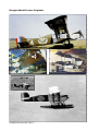
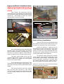
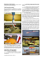
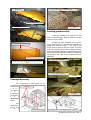
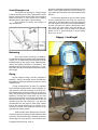
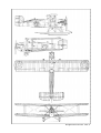
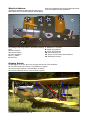
Douglas World Cruiser
1924 Around the World
United States
Assembly Manual
for ARF stand-off scale model in 1:5 scale.
Historical data and presentation.
Model design and drawing by
K&W Model Airplanes Inc. ©
USER'S MANUAL
Douglas World Cruiser ARF 1
Douglas World Cruiser Originals
Douglas World Cruiser ARF 2
The Douglas World Cruiser
Donald Douglas started manufacturing
airplanes in January 1920, when he left chilly
Cleveland for balmy California, determined to
make it on his own. He had only $600 and a
family to support. Fortunately, he found financial backing from wealthy David R. Davis, who
had $40,000 to back an aircraft manufacturing
company, provided it built an airplane that
would make the first nonstop, coast-to-coast
flight.
The Davis-Douglas Company set up
shop first in the back room of a Pico Boulevard
barber shop and then in a 3,600-square-foot
loft above a Los Angeles planing mill. Helped
by a staff of five former employees of the Glenn
Martin Company, Douglas designed and built
the Cloudster which first flew Feb. 24, 1921.
In June 1921, the Cloudster set out for
its flight from March Field, California, to Curtiss
Field, New York, but engine trouble forced it to
make an emergency landing in Texas, and it
was flown back to March Field for installation
of an improved engine. By then, Douglas had
landed a contract to build torpedo bombers for
the Navy, starting with the DT-1 (Douglas torpedo, first), followed by the DT-2 production
version.
The DT-2 was redesigned as the basis
for the Douglas World Cruiser (DWC) and was
selected as part of a secret military project to
build the first airplane to circumnavigate the
globe. The DWC had a modified fuel system,
extra struts and a differently shaped vertical
tail service than the DT.
Douglas built five DWCs for the Aviation Service of the U.S. Army. Four of the
planes, the Seattle, the Boston, the Chicago
and the New Orleans, left Santa Monica, Calif., for Seattle, March 17, 1924, and left Seattle April 4. The Seattle was lost during a
Pacific storm over Dutch Harbor, Alaska. The
Boston made a forced landing in the mid-Atlantic.
The other two DWCs were kept flying
with the help of 15 extra engines, 14 extra
sets of floats and duplicates of all the airframe parts, stashed at various sites around
the world. The Chicago and New Orleans circled
the globe and returned to Seattle Sept. 28,
1924. They flew 27,553 miles in six months
and six days and earned the company its motto
“First Around the World - First the World
Around.”
The fifth DWC was tested and delivered to the Army Air Service for test and approval. It was later renamed Boston II and
used to replace the first Boston, and with the
first Boston’s crew, completed the flight around
the world.
The Historic Flight Around the
World
With the successful crossings of the
Atlantic in 1919 by the U.S. Navy’s NC-4 and
the British flyers, Alcock and Brown, in a Vickers Vimy, the ambition to circumnavigate the
globe by airplane was a natural next challenge. The British made an unsuccessful attempt in 1922. The following year a French
team tried and failed, and another British effort was being organized, but was abandoned.
The Italians and Portuguese were also discussing plans for a round-the-world flight at
this time. In July of 1923, United States War
Department disclosed that it was sending two
officers on an information-gathering trip to
stake out a route for a global flight to be attempted by the U.S. Army Air Service in 1924.
Maj. Gen. Mason M. Patrick, Chief of the Air
Service, was put in charge of planning and
directing the flight.
For the flight, the Air Service commissioned specially-built aircraft from the Douglas Aircraft Company in Santa Monica, California. The design was a sturdy, 15-m (49-ft)
span, two-place biplane powered by a single
twelve-cylinder, water-cooled 400-horsepower
Liberty Engine. A total of five airplanes were
built, including a prototype for testing. The
Douglas World Cruisers, as they were named,
could be equipped with wheels or pontoons,
depending on the terrain from which they were
operating. The aircraft did not have radios or
advanced navigational aids, only the standard
rudimentary flight instrumentation of the day.
The four World Cruisers built for the
round-the-world attempt were christened the
Seattle, the Chicago, the Boston, and the New
Orleans, to represent the regions of the United
States. Four of the Air Service’s top pilots were
selected. Major Frederick L. Martin was designated overall flight commander and flew the
Seattle. Lt. Lowell H. Smith, Lt. Leigh Wade,
and Lt. Erik H. Nelson piloted the Chicago, the
Boston, and the New Orleans respectively.
Each pilot was permitted to select his own
mechanic/co-pilot. The crews trained at Langley Field in Virginia in navigation and meteorology, and practiced with the prototype airDouglas World Cruiser ARF 3
The four World Cruisers built for the roundthe-world attempt were christened the Seattle, the Chicago, the Boston, and the New
Orleans, to represent the regions of the United
States. Four of the Air Service’s top pilots were
selected. Major Frederick L. Martin was designated overall flight commander and flew the
Seattle. Lt. Lowell H. Smith, Lt. Leigh Wade,
and Lt. Erik H. Nelson piloted the Chicago, the
Boston, and the New Orleans respectively.
Each pilot was permitted to select his own
mechanic/co-pilot. The crews trained at Langley Field in Virginia in navigation and meteorology, and practiced with the prototype airplane while the flight aircraft were being constructed and prepared.
In the meantime, elaborate preparations
were being made for fueling and repair sites at
strategic locations along the route, arranging
of overflight and landing clearances, and securing the cooperation of the U.S. Navy and
the Royal Air Force. Because the United States
did not recognize the Soviet Union at this time,
flying over Siberia was prohibited, necessitating a southeast Asian route that added 11,000
km (6,875 mi) to the journey.
After practice with the four flight aircraft in Santa Monica and San Diego, the crews
headed north to Seattle, the official point of
departure for the round-the-world flight.
Shortly after setting off on the first leg of the
trip on April 6, 1924, Major Martin, piloting the
lead airplane, the Seattle, fell behind. Engine
trouble forced him down and the other World
Cruisers continued on. After an engine replacement, Martin and his mechanic, Sgt. Alva
Harvey, attempting to catch up with the others waiting at Dutch Harbor, Alaska, departed
in questionable weather. The Seattle crashed
into a mountainside after getting lost in fog.
The airplane was destroyed, but luckily Martin
and Harvey escaped with minor injuries. Lt.
Smith, piloting the Chicago, took over as flight
commander.
Much of the rest of the trip passed
with relative good fortune. The three remaining World Cruisers continued on via the northern Pacific chain of islands en route to Japan.
The three aircraft then traversed China,
Indo-China, Siam (Thailand), Burma, India,
Persia, Asia Minor, the Balkans, and France.
From Strasbourg, they were escorted to Paris
by the French Air Force, and there they received a tumultuous welcome from cheering
crowds on July 14, Bastille Day. The next day
they left Paris and landed in London.
Douglas World Cruiser ARF 4
Disaster occurred again, however, over
the north Atlantic between the Orkney and
Faroe islands, when the Boston suddenly lost
oil pressure and had to alight in the ocean.
Although the landing was successful, the Boston was damaged beyond repair during an attempt to hoist it on board a Navy ship. The
World Cruiser fleet was thus reduced to two,
but at Pictou, Nova Scotia, the prototype aircraft arrived to join the remaining two and
became the Boston II. From there the planes
flew on for a triumphal journey across the
United States, arriving in Seattle on September 28. The 44,085 km (27,553 mi) flight was
completed in 175 days-a flying time of 371
hours 11 minutes-with an average speed of
112 kph (70 mph).
The 1924 round-the-world flight remains
one of the truly great achievements in aviation. It was an incredibly arduous trek. The
loss of two of the airplanes and the close call
for Major Martin and Sgt. Harvey in the crash
of the Seattle were hardly the only setbacks.
Throughout the journey the crews prevailed
against an endless series of forced landings,
repairs, bad weather, and other mishaps that
continually threatened the success of the
flight. Further, it was a monumental logistical
accomplishment. More than just an aviation
milestone, the flight was an important step
toward the goal of world-wide air transport in
the decades to come.
Two weeks before the Douglas World
Cruisers completed their flight around the world,
a young museum aide named Paul E. Garber
recommended that the Smithsonian Institution
should acquire one of the aircraft for its collection. Eleven months later, the Secretary of
War approved the transfer of the Chicago to
the Smithsonian.
On September 25, 1925, this aircraft
made its final flight from McCook Field in Dayton, Ohio, to Bolling Field in Washington, D.C.
Later that fall, the airplane was placed on public display in the Smithsonian’s Arts and Industries building.
The Chicago was restored in 1971-1974
and moved into the new National Air and Space
Museum building in 1976. Of the five Douglas
World Cruisers built, the New Orleans is the
only other survivor. It is in the collection of
the Los Angeles County Museum of Natural
History and was on display at the United States
Air Force Museum from 1957 to 1988, and subsequently at the Museum of Flying in Snata
Monica, California.
Engine and Radio installation Note:
Remove top wing section from the
cabane and remove all aluminum
panels
First remove the aluminum cowl by
unscrewing the 2mm machine screws holding
the cowl to the engine bay.Remove the dummy
engine by unscrewing it from the motor
mounts.Refer to pictures below
Screws
Motor Mount
Screws
Mount Tank and Throttle Servo here.
Radio & Sevo Installation
Remove the aluminum panelling around
the cockpit by removing the 2mm screws. This
will give you access to the servo locations.
We recommend flying this aircraft with
at least a 1.80 , four stroke engine. The engine
can be readily mounted in the engine bay. You
will have to remove a portion of the dummy
engine to allow for the cylinder head cooling.
The tank and throttle servo can be
mounted behind the engine. Yor will have to
make a small servo support for the throttle
servo out of scrap wood.
If you decide to use a gas engine, you
will have to make a suitable motor mount. The
gas engine can be mounted upside down quite
readily.
The pictures below show the engine
bay covered and uncovered. The entire
aluminum covering can be removed so that
you can readily modify the engine mounts as
required.
Mount the Elevator rudder servos in
the spaces provided. Connect the servo arms
to the control stick and rudder bar with short
pieces of music wire with threaded ball links
on either end. Install ball links on the control
column and rudder bar as required.
The picture below shows the location
of the control stick and the rudder bar in the
servo/radio receiver bays. The battery pack
can be mounted anywhere in this bay, with
the switch mounted on the cockpit formers.
Be sure to fasten the battery pack securely.
Picture of Servo bay, the cocpit and bottom
covering has been removed.
Rudder bar
Control stick
Douglas World Cruiser ARF 5
Place Sevos in this cutout
Connect them to the rudder bar and the control
column with rods and ball links
Tail Group Assembly
The tail group is designed to easily
disassembled for transport. The horizontal
stabilizer is held to the fuselage with three
Nylon Screws.
Nylon Screws
Horizontal Stabilizer supports
2. Install the upper wing halves in the
same manner. Wing is attached to the center
Cabane.
3. Fasten the tie straps on the upper
and lower wings with the screws provided.
3. Install the interplane wing struts. The
struts are packaged in marked plastic bags. It
is recommended that you mark them individually after installation for ease of disassembly.
Connect the strut cross bracing by clipping
the kwick links in place.
4. Attach the landing and flying wires
according to the sketch below and on the last
page of this manual. The wires have all been
precut and the plane was completely rigged
at the factory. So each wire should be at the
correct length for attachment..
5. Install the aileron interplane connecting rods.
6. Install the Airleron servos in the wells
provided in the top wing. There is a tube
preinstalled int the cabane strut. Feed a piece
of servo wire through this tube and install connectors on both ends. These connectors will
then connect to the aileron servo and the radio in the fuselage. Connect the aileron push
rods to the servo and check the throw of the
ailerons (20° up and down). For ease in control you may adjust the servo arms to give
differential throw in which case the up deflection should be 30°.
Servo Access bay
Vertical Stabilizer supports
Landing and Flying wires
Dowel
Bracket
The Vertical Stabilizer is held with a
dowel at the leading edge and a double L
bracket at the trailing edge. The rudder is fixed
with hinge points that are glued into the rudder
and held with screws in the vertical stabilizer.
Inter Plane Struts
Wing Rods
Assembly of wing panels
Refer to pictures on the Right
1. Install the lower wings by aligning
the rods with the holes in the wing and inserting fully.
Douglas World Cruiser ARF 6
Pre Rogged Landing wires
Access through the rear cockpit
Wing Rods
Aileron control Rod tube
Lower Wing Rods
Joint
Landing gearAssembly
Push the landing gear supports in the
holes in the fuselage. Secure with the straps
and screws provided.
Wing connecting straps
Anchors for Flying wires
Install the Gear supports to the lower
wing. seat securely in the holes provided and
install the retainer straps. The end of the
lower strut is the axel for the wheel. The axel
is fed through the slot in the support bracket
and retained with a Bungie (rubber bands) cord.
See the sketch below for guidance in installing
the bungie cord. This is a very efficient shock
absorber.
Upper Gear Support
Wing connecting straps and anchor for flying
wires
Lower Gear Support
Bungie
Fuselage Assembly
The Fuselage is designed to be
separated
Screws
behind the
r e a r
cockpit.
T
h
e
Fuselage is
shipped in
t
h
e
disassembled
state.
Too
assemble,
align the
t
w
o
Alignment Dowels
Brackets
Cutaway view of the landing gear supports
Douglas World Cruiser ARF 7
Install Bungie cord
The axels are sprung by using bungie
(rubber bands) cords. The combination of the
bungie cord and the spring steel in the support
that terminates in the wheel axel supply
adeqate shock absorption upon landing.
The method of lacing the bungie is
depicted below.
aircraft is limited aerobatic like all biplanes from
WW 1. Remember that all turns are made using rudder and elevator and compensated with
aileron!
The landing approach can be rather steep
as per prototype but the flare out needs almost full up elevator. Once on the ground keep
the tail down to maintain directional stability.
In case you have to make a dead stick landing, keep the nose down and the speed up.
The wires produce a lot of drag! It is always
better to do a good landing in a bad place
than vice versa...
Happy Landings!
Lacing
of
bungeerubber
for the wheel
shaft
Balancing
The C/G (center of gravity) or balancing point should be no further back than approx.
14 cm (5½”) measured from the center of the
leading edge on the upper wing. Make adjustments by adding wheight if necessary. The
allowable range of the CG is around +/- 2 cm.
The plane will be controllable and stable within
this range.
Flying
Let the engine swing a 14"x6" propeller if
possible. This gives better thrust outside the
big radiator front and reduces sound to a more
realistic level.
Flying characteristic is that of a biplane
from the WW-I period and it will fly happily on
3/4 throttle. Ground handling on a hard surface demands a gentle hand but on grass surface, the tailskid provides enough directional
stability. During the initial take off run first
keep full up elevator to keep the tail down. As
the speed builds up, let go gradually of the up
elevator and the tail comes up. You have to
compensate for the torque with right rudder
but as the speed builds up the rudder is returned to neutral. This model should fly of the
ground and not be pulled.
Unlike many other planes from this period this type has a lifting profile stabilizer that
in theory should offset the climbing tendency
of the high lift wing profile. Once airborn the
Douglas World Cruiser ARF 8
Douglas World Cruiser ARF 9
What is in the box:
wires are supplied in the correct lengths and need
only to be clipped to their positions.
The ARF kit contains the parts shown in the picture.
All the parts are covered and painted. All the rigging
12
8
8
9
9
11
3
1
5
4
7
6
10
2
11
10
1. Fuselage with wing cabane, detachable landing
gear.
2. Scale wheels
3. Dummy Engine
4. Scale propeller
5. Fin / rudder
6. Tail skid.
7. Stabilizer / elevator
8. Upper wing panels
6
9. Lower wing panels
10. Interplane struts
11. Wires, turnbuckles and hardware
12. Assembly manual
Rigging Details
1. All rigging wires are precut to length with quick links attached.
2. Connect cross brace wires, colored Blue in photo.
3. Connect Flying Wires, colored Black in photo.
4. Connect Landing Wires, Colored Red in photo.
3
4
Douglas World Cruiser ARF 10
2
Assembly Manual
for ARF stand-off scale model in 1:5 scale.
Historical data and presentation.
Model design and drawing by
K&W Model Airplanes Inc. ©
P.O.Box 1229, Cebu City Centrl. Postoffice
Cebu City 6000, Philippines
Visiting address:
3343 Gun-Ob, Kinalumsan,
Lapu-Lapu City 6015, PHILIPPINES
Phone +63 32-340 0772, Cellular +63 917-3200 985
Telefax +63 32-340 7131, E-mail: [email protected]
Website http://www.kwmairpl.com.ph
Douglas World Cruiser ARF 11