1
PART TWO
The Fine Old irt Of Rigging 1 Riplane
By Bob Whittier, EAA 1235
57 Swift Ave., Osterville, Mass.
When the center section is all done and the lower
wings are hanging by the landing wires, it is time to install the upper panels. Depending on the ship's size, it
can be easy or a struggle. Lay a plank across two step
ladders at convenient working height just outboard of the
wing tip so that two men can lift the tip to proper height
while a couple others raise the root end, using the lower
wing's walkway and the landing wheel for steps. Have
handy spikes, awls, drift pins, Phillips screwdrivers, etc.,
to shove into strut, root and wire fittings quickly and take
the strain off the men. Then one by one put the correct
bolts in place.
Set the bubble protractor at the specified degrees of
wing dihedral. Place the straightedge on the top of a
lower wing as in Fig. 7 and by turning up the landing
wire bring in correct dihedral. Sometimes it's necessary to
bring the bubble a little past the line to take into account
wire slackness; when the flying wires are tightened later,
dihedral will be pulled down to the correct amount. Once
the protractor has been set, do not change it until dihedral rigging is done, because one's hands and eyes are
not sensitive enough to get exactly the same setting two
or three times in a row. Put pencil marks on the wing to
show where the straightedge was laid, so it can be replaced exactly if need be for a later check. If there are
two landing wires on each side, use only the front one
to rig in dihedral at this stage.
At this point, careful center section adjustment and
carefully made wing root fittings will be holding upper
and lower wing panels at the correct angle of incidence
at the roots. Next step is to rig that angle into the panels
all the way to their tips. Place the incidence board under
the lower wings at or just outboard of the interplane
struts, as the men in Fig. 5 are doing. If the ship has two
landing wires, use the rear one to raise or lower the trailing edge. Or perhaps the rear interplane strut has a
threaded fitting. Then rig incidence into the top wings
with whatever strut or wire adjustments are obvious.
Then things can be tightened up, turning each of the
several wires about half or one turn at a time in orderly
fashion. Never use pliers or common wrenches on them!
Saw and file a half-streamline shaped notch into the end
of a brass or aluminum rod or bar, to fit the wire section
nicely, and use that for turning them without causing
dangerous scratches. Don't pull wires up agonizingly
tight, for that will strain fittings and warp wooden structural members. Fair tension is ample. If a wire flutters on
the test hop, it can be tightened a little . . . though you
may find that has slacked off another one, which will
then start wiggling! That's why they use "javelin struts"
where the flying and landing wires pass each other as on
the Waco 9, Fig. 3. These are of wood, taped on.
There is a difference of opinion in old texts on the
question of rigging some wash-in or wash-out into biplane wings, to counter propeller torque's tendency to roll
a plane in the opposite direction. One school of thought
points to the corkscrew path of the prop slipstream. Obviously it makes the relative wind blow up on one wing
root more, and blow somewhat down on the other one,
resulting in an automatic difference in lift, changing with
CX1N3MIU2
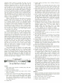
Fig. 7.
Measuring dihedral.
engine speed to counteract torque. Others say to use washin and wash-out, one old text recommending an inch of
wash-in on biplanes powered by 100 hp engines! Some
say to use wash-in only, others to divide the required
corrective force between opposite lower wings with washin and wash-out.
It seems that the validity of the slipstream theory
would depend on the relation of wing span to propeller
diameter. The eight and nine-foot propellers on slowturning 100 to 250 hp radial engines obviously puts prop
wash over a considerable proportion of the wing area in
biplanes of 28 to 30 foot span. But most texts describe
the wash-in, wash-out method. Unless specific rigging
data is available it might be best to test hop a biplane
with no wash-in or wash-out, note wing heaviness, and
adjust accordingly. If an undue amount of wash-in (higher
angle of incidence) is needed to correct torque, it can
lead to premature stalling of the wing tip concerned so
it would be well to divide corrective measures between
some wash-in on one wing and wash-out on the other side.
Old biplanes with plain ailerons and unwarped wings can
lose aileron control quickly and completely in a stall.
Read pages 163-175 of "Stick and Rudder" by Wolfgang
Langewiesche before flying an old biplane!
Still talking of torque correction, remember that
when the wings are warped to counter it, any particular
adjustment will work only for one air speed. Usually
things are set to make the plane fly level at cruising
speed — but that can vary with load though the engine
rpm is held constant. Torque effect shows up more in bigpropellered, short-spanned biplanes than in today's smallpropellered, large-span monoplanes. Odd things in an
old biplane's flying characteristics often are based on
the nuances of torque and those big propellers. For example, if the engine is throttled back fully when gliding
in to land, the big prop will windmill and slow down the
flow of air through it. This retarded air stream passes
over a sizeable proportion of the wing area and it makes
the ship come down a lot faster than the average monoplane. Carrying a small amount of power in the approach
lets wind flow through the prop without retardation and
the approach is less bricklike! The same applies to today's midget biplanes, whose propellers are large in diameter relative to the span.
One cannot change the length of a strut or wire without changing others in its group to allow for the altered
length. If a terminal is screwed out too far, too few
threads do the holding job and there's danger of their
SPORT AVIATION
JS
stripping. When starting to assemble the plane, run end
fittings on as far as common sense says they can or
should go. Frequently there is a tiny hole in the side of
terminal barrels, as can be seen in Fig. 8, so that a wire
can be poked in to see if threads have gone in at least
that far from the end. If, after rigging, you cannot feel
the rod threads, safety demands that rigging be changed
to allow that minimum number of threads to be engaged.
Fig. 8 also points out that there are two measurements to
take into account when working with or ordering tie rods.
New streamline tie rods ?re expensive but can still be
ordered to fit through supply houses such as Air Associates or from a manufacturer such as the Macwhyte
Company of Kenosha, Wis.
Match up left and right wires and struts to have them
of equal length before starting. Tie rods have left-hand
threads on one end and right-hand on the opposite end.
It is standard practice to have the right-hand thread
ends at the lowermost, innermost and forwardmost points,
so mechanics won't become confused as to which way
the various lock nuts should be turned. Lightly grease
threads before installing terminals. Do not jam lock nuts
up very tight, for that puts a concentrated pull on the
wire at that point; added to the normal flight stresses
it could make a tie rod part.
Ailerons normally carry an up-load, and depending on
the stretch characteristics of the control cable system,
will or will not be affected in flight. Sometimes they
are rigged so their trailing edges are even with the wing
trailing edges on the ground. In other ships, they are
rigged with their trailing edges from V* in. to Vz in. low so
that air loads in flight will hold them even with the wings.
Less frequently, they are rigged to ride slightly above the
wing trailing edges when in flight, perhaps an eighth of
an inch, on the theory that this reduces overall airfoil
incidence at the tips and causes that area to stall later
than the rest of the wing so as to retain aileron control
longer. If rigging data is lacking, rig them even with
the wings and make test flights to decide if changes
would help aileron effectiveness.
Some biplanes have no dihedral in the upper wing,
and in these it is often the practice to set the top wing
in place, rig it straight, and use it as a reference point
to get the proper dihedral into the lower ones. The Fleet
biplane is an example. Partly to illustrate typical, actual
factory rigging instructions of the 1920's and 1930's and
partly to make the information available to antique enthusiasts, herewith are erection and rigging instructions
for the Fleet and Waco F airplanes.
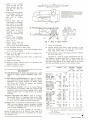
-PIN CENTER LENGTH ——— ROD LENGTH——
Fig. 8. Measuring an aircraft tie
rod. Note safety holes in terminals.
FLEET:
1. Place upper panel upright on leading edge, with padding on the floor.
2. Attach all interplane struts.
3. Raise panel above fuselage and attach center section
struts to fuselage.
4. Attach center section wires and tighten to fair tension.
5. Attach lower panels to fuselage; tighten and cotter
nuts. Lower wing-to-fuselage attaching bolts should
be a snug fit without play; use 1/64 in. or 1/32 in.
oversize bolts in reamed holes if there is play. Should
be a light drive fit.
26
MARCH 1963
6. Attach landing and flying wires; left-hand thread at
upper ends.
7. Level fuselage. Top longerons and cross tubes in both
cockpits may be used or both bottom longerons and
cross tubes between front and rear lower wing spars.
8. Drop plumb lines D, Fig. 4, from leading edge of upper
panel at points in line with center section strut attaching points. Measure distances X and Y from bottom longeron to plumb lines and adjust wires A and
B until X and Y are equal and center section is level.
9. Drop a plumb line from leading edge of upper panel
at outer strut attach points; measure distance from
leading edge of lower panel to plumb line for stagger. This should measure 23 in., both sides symmetrical within l/» in. and can be equalized by adjusting
center section adjustable struts.
10. Dihedral of lower panel is 4 degrees. Upper wing has
no dihedral. Center section of upper wing has been
leveled as in (8). Level remainder of upper wing by
adjusting landing wires L so that upper wing is
straight, taking care that flying wires F are slack
enough to allow this. Then tighten up flying wires
F. Lower dihedral may be checked if desired.
11. Using incidence board, Fig. 6, adjust lower outer panel
incidence to zero degrees via the adjustment on the
rear interplane struts.
12. All streamline wires are lined -ip with the air stream
and lock nuts tightened.
13. Insert bakelite spacers at all streamline wire crossings
and tape. Use two of them at center section wire
crossing and four on each side at flying and landing
wire crossing.
14. Grease hinges on wings and ailerons, and inside of
operating arm on inner end of ailerons.
15. Approach wing with aileron from rear, sliding aileron
operating lever, on aileron, through opening in rear
spar over operating lever tube in wing.
16. Push aileron forward until hinges mate.
17. Insert greased hinge rod through hole in wing tip bow.
Secure with two drilled head fillister machine screws
at outer end and safety wire.
18. Support ailerons with ¥4 in. droop on each. Support
stick in neutral and adjust fork ends on inner ends
of operating tubes to match holes in operating lever
in cockpit, locking fork at proper adjustment with
lock nut. Connect operating tubes to operating levers
with bolts and bushings. If droop of ailerons on
ground is such that trailing edges do not line up in
flight, adjust to correct.
19. If in hands-off flight one aileron droops and the other
rides high, the ailerons are unsymmetrical in contour,
the high degree of balance of these ailerons making
them sensitive to changes in contour. This produces
an apparent wing heaviness that is corrected with the
ailerons rather than on the wing rigging. On the under surface of the aileron near the outer end two
ribs are provided with a variable camber device. Cover
is cut to reach them. Two screws are turned to change
camber, backing them off until the aileron rides
evenly in flight on the one which rides high. Test fly
until satisfactory.
WACO F:
1. Remove streamline wire-end terminals and screw them
back on five complete turns to insure an equal amount
of adjustment on each threaded end.
2. Bolt center-section struts to center-section.
3. Mount center section on fuselage.
4. Fasten center section wires.
5. Adjust c e n t e r section
wires so that the distances between pin centers are the same on
both wires.
6. Fasten front and diagonal interplane struts on
upper wing with adjustment ends at bottom.
Fig. 9a.
7. Mount
lower
wing
{———— - - - ————
(d) Front Landing Wire
/- Ctnlcrscction tvires
2-Frontftying iv/res- We'*!/}/* 'acnalmrettnytti
3-Rtar flying tv/rts- s/te'xfOSfo'acfijatNim/engt
4 - front landing wires* '/* ''*96 'actual
'
wire length
5-Reartanding>virts-'/4ii9/l'i'acrua/tYirr/engtt>
6 - Adjustment for snort struf
7 - Adjustment for /ong strut
0- Adjustment for Ai/cron strut
on
wing fittings on fuselage,
and insert % in. bolts,
long one front, short one
rear. Wing tip must be
propped up in position
until upper w i n g is
mounted a n d landing
wires are fastened and
tightened.
8. Fasten long
interplane
strut to rear of diagonal
strut. Fig. 9a.
9. Mount upper wings on
center section, u s i n g
5/16 in. bolts with taper bushings.
10. Bolt interplane strut on lower wing.
11. Put on landing and flying wires, with left-hand thread
to the top. Don't tighten.
12. Draw up front landing wire to 94Vs in. between terminal ends, Fig. 9d.
13. Tighten rear landing wire until tension on both wires
is equal.
14. Tighten flying wires.
15. Wings are rigged with no warp, as no allowance for
propeller torque is needed.
16. Adjust interplane struts.
Fig.
9.
Waco F rigging diagram.
17. Cotter all fastenings.
18. Connect aileron push tubes under fuselage so that
both lower ailerons are even with the wing trailing
edge when control stick is in neutral.
19. Adjust aileron struts so that upper and lower ailerons
are even with wing.
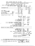
Herewith is a table of rigging specifications for several biplanes, reprinted from CAA Aviation Safety Release No. 317, April 7, 1949. The gap figures given for
the Great Lakes biplane do not make sense to the writer
but they are printed as given in that official release.
STAGGER
MODEL
GAP
BIBLIOGRAPHY
"Aircraft Maintenance" by Brimm and Boggess has a good
chapter on rigging. Pitman Publishing Corp., N.Y.,
1937.
"Aviation Service and Maintenance" by James G. Thompson, Aviation Press, Los Angeles, 1937, has service,
adjustment and rigging chapters on Wacos, Fleets
and Travel Airs. Travel Air chapter has detailed
rigging chart for all models.
"A Text Book on Aviation", Vol. II, Lt. Leslie Thorpe,
Aviation Press, Los Angeles, 1935, has a chapter that
reproduces entire Fleet service manual. Also a good
rigging chapter. Part of "Cadet Series" of aviation
textbooks.
"Airplane Construction and Repair", John E. Younger,
McGraw-Hill Book Co., Vocational Texts series, 1931,
has a good rigging chapter with data on Fairchild
71. Fleet, Waco F, Fokker Universal, Boeing 40.
"Aviation, Vol. 2" by American Technical Society, Chicago,
1945, has good rigging chapter including coverage
of method of assembling wings on double-bay biplanes
such as Jenny, Fledgling, etc.
A good source for used textbooks of all kinds is
Barnes & Noble, 5th Ave. at 18th St., New York, N.Y.
Also try book-finding services in classified ads of Popular Mechanics, etc.
INCIDENCE
degrees
lower upper
DIHEDRAL
degrees
lower
upper
5>A' at
10"
Eaglerock A-l
fleet 1, 2, 7
23" ± V
9.63"
Fairchild KR34C
Fairchild KR21
14"
25"
Great Lakes 2T1-A*
26-7/32"
Navy N3N-3
34"
New Standard D-2S
30"
Bird A, BK, CK
22 '/,"
Stcarman C3R
28"
Stearman PT-17
tips
63y4"
1%
0
l'/4
1'/2
I'/l
0
2Vi
21/2
4
1
0
0
3
2'/2
2
3
2
2
* *
2
4
0
l J /4
2
3
l'/2
0
1
1
3
3
l'/2
0
21/2
2 'A
0
3'/4
0
0
0
2
4
0
2
2
63"
25" CS
3
12.8" IS
65"
2
»•
**
58"
2
63" at root l J /4
72" at root 4
2
>/4
0
2
Travel Air 2000
and 4000
Travel Air E4000
Waco GXE, ASO
Waco RNF, INF
Waco QDC
Waco QCF
Waco DEC
Waco UIC
Waco UKC, VKC,
VKS
Woco YKC, YKS,
ZKS
Woeo YOC*'*
251/2"
29"
low
281/,"
33-5/16"
33%"
581/2" RS
551/j" IS
61 1/2"
621/4"
54"
0
0
0
SS'/i"
551/j"
SSi/j"
53V,"
0
0
0
0
31-5/16"
53-1/16"
0
0
2'/2
2«/i
31-5/16"
53-1/16"
49" RS
0
0
0
0
2i/j
2V2
2V2
2'/2
31-5/16"
331/2"
38%"
0
0
l J /4
! J /4
2
2
2V2
2 'A
2V2
2'/2
NOTE: RS= Root Section. IS= Interplone Struts. CS= Center Section.
* Great Lakes wing sweepback in degrees, lower 0, upper
9
deg. 30 sec.
** No data available.
*** Waco YOC wing sweepback in degrees, upper ond lower, 2'/2-
SPORT AVIATION
27