1
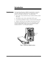
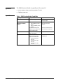
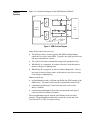
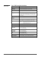
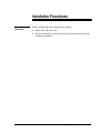
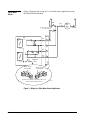
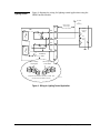
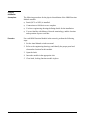
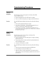
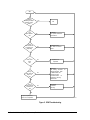
Metasys Network Technical Manual 636
Function Modules Section
Technical Bulletin
Issue Date 0793
Output Relay Momentary Function Module
Introduction
3
●
Description
3
●
Application
4
●
Capabilities
4
●
Theory of Operation
5
●
Specifications
6
Installation Procedures
7
●
General Information
7
●
3-Wire Motor Starter
8
●
Lighting Control
9
●
Physical Installation
Commissioning Procedures
10
11
●
Physical Verification
11
●
Software Verification
11
Troubleshooting Procedures
©
Page
13
●
Troubleshooting Chart
13
●
Ordering Information
15
1993 Johnson Controls, Inc.
Order No. 636-053
1
2 Function Modules—Output Relay Momentary Function Module
Introduction
The Output Relay Momentary (ORM) Function Module is an interface
between the DCM and 2-state field devices. This function module
provides on/off control of field devices. The ORM features:
●
Form A and C relays and interface logic to enable the DCM to control
these relays
●
Auto/Manual switch (A-M) to enable/disable DCM control
●
two momentary pushbutton switches (1 and 0) for manual intervention
●
feedback indication of the Auto/Manual switch setting to the DCM
The ORM Function Module plugs into any one of the bottom ten slots
associated with the DCM. Figure 1 shows typical function module
locations in the NCU. A five slot panel is pictured.
Output FMs
DCMs
I
A
M
orm101
O
OR M 101
Description
Figure 1: ORM Function Module Locations
Function Modules—Output Relay Momentary Function Module
3
Application
Capabilities
The ORM Function Module is typically used for control of:
●
motor starters using a start/stop station (3-wire)
●
lighting contactors
Table 1: ORM Function Module Capabilities
Capability
Description
Purpose
Input from DCM
DCM inputs a digital command.
Allows DCM to provide automatic
control of outputs.
Auto/Manual Switch and Two
Momentary Pushbutton
Switches
Switch selects one of
- Auto—DCM/relay control of
outputs.
- Manual—DCM/relay control
disabled.
Pushbutton switches provide
override control of output in both
Auto and Manual modes.
Allows for manual override of
DCM control for special
situations.
Power on Reset
At low power or after power up,
relay is de-energized.
Provides controlled restart.
Output to Field
Module provides contact closure
control on three leads with
respect to a common lead:
- Relay A (Form A type)
N.O. lead
- Relay B (Form C type)
N.O. lead
- Relay B (Form C type)
N.C. lead
Provides contact closure control
of field devices.
4 Function Modules—Output Relay Momentary Function Module
Allows for local/manual control,
even if the DCM is not present.
Theory of
Operation
Figure 2 is a functional diagram of the ORM Function Module.
ORM
Relay
"A"
N .O .
(A )
"1"
COM
Control
Electronics
N.O.
(B)
R e la y
"B "
Field
Device
"0"
N.C.
(B)
A
M
A u to /M a nu a l
S w itch
orm 101
Figure 2: ORM Function Diagram
Under DCM control, the process is:
●
●
●
●
The DCM provides a control signal to the ORM to independently
control the two relays in the ORM. Typically, the signal provides start
and stop commands for a motor.
The control electronics momentarily energize the appropriate relay.
When Relay A is energized, its contacts close the circuit that starts a
motor or energizes a lighting relay.
When Relay B is energized, its pair of contacts change state. One set
may open a circuit to stop a motor, or the other set may close a circuit
to de-energize a lighting relay.
Manual controls are:
●
●
●
an Auto/Manual switch (A-M) that can disable the DCM control of the
ORM relays. The status of this switch is reported back to the DCM.
a momentary pushbutton (1) that closes the same circuit as the
Relay A contacts
a momentary pushbutton (0) that closes and opens the same pair of
circuits as the pair of Relay B contacts
The two pushbuttons operate with the Auto/Manual switch in either
position. The pushbuttons mechanically control the circuits and work
even if the NCU or NEU is not powered up.
Function Modules—Output Relay Momentary Function Module
5
Specifications
Table 2: ORM Function Module Specifications
Category
Specifications For Configurations
Product Code Number
FM-ORM101
Output Range
Two states (contact open/closed) on each of three leads
Output Limits
1 amp
Output Protection
Common output fused at 3 amps with a slow blow, non-field replaceable
fuse.
Relay Type
Form A relay having a Normally Open (N.O.) contact.
Form C relay having a Normally Open (N.O.) and Normally Closed (N.C.)
contact with a common connection between them. Contacts are “breakbefore-make” type.
Relay Contact Rating
120 VAC, at 1 amp max., pilot duty
Relay Insulation
Resistance
1,000 M ohms (min.) from contacts to coil
Relay Dielectric Strength
2,000 VAC, 50/60 Hz, (for 1 min.) from contacts to coil
1,000 VAC, 50/60 Hz, (for 1 min.) between N.O. and N.C. contacts
Relay Service Life
Mechanical:
Electrical:
10,000,000 operations
300,000 operations for inductive load at 120 VAC, at
1 amp with a power factor of 0.4
Response Time
Maximum:
100 msec
Default Condition
At low power or after power up, relay is de-energized.
Source Power
Power is from the PWR in the NCU/NEU.
Operating Environmental
Requirements
32 to 122°F (0 to 50°C)
10 to 90% noncondensing RH
86°F (30°C) maximum dew point
Storage/Shipping
Environmental
Requirements
-40 to 158°F (-40 to 70°C)
5 to 95% noncondensing RH
86°F (30°C) maximum dew point
Size
0.85 in. H x 2.6 in. W x 7.0 in. L
(2.2 cm H x 6.6 cm W x 17.8 cm L)
Weight
0.5 lb (0.22 kg)
Agency Compliance
FCC Part 15 Subpart J—Class A, UL 916, CSA C22.2 No. 205
Agency Listings
UL Listed and CSA Certified as part of Metasys®
6 Function Modules—Output Relay Momentary Function Module
Installation Procedures
General
Information
When installing and connecting function modules:
●
●
follow NEC and local codes
observe maximums as specified in the specification table and in these
installation guidelines
Function Modules—Output Relay Momentary Function Module
7
Figure 3 diagrams the wiring for 3-wire motor starter applications using
the ORM Function Module.
3-Wire Motor
Starter
X1
X2
Start
Stop
W ire G a u g e a n d L e n g th
Per Local Codes
Aux
TBF
ORM
Relay
"A"
N.O.
(A)
1
COM
3
N.O.
(B)
4
N.C.
(B)
5
"1"
Relay
"B"
"0"
A
M
Auto/Manual
Switch
T B F in le ft b a y
o f N C U /N E U
3
6
2
5
1
4
T B F in rig h t b a y
o f N C U /N E U
1
4
2
5
3
6
S trip w ire a n d in se rt in sid e fa ce o f T B F . U se
se t scre w in fro n t face to secu re .
orm wire
Figure 3: Wiring for 3-Wire Motor Starter Application
8 Function Modules—Output Relay Momentary Function Module
Motor
Starter
Holding
Coil
Overloads
Figure 4 diagrams the wiring for lighting control applications using the
ORM Function Module.
Lighting Control
X1
TBF
ORM
Relay
"A"
N.O.
(A)
1
COM
3
W ir e G a u g e
a nd L en gth
Per Local Codes
(2 4 V A C
or
120 V AC )
2 -c o il
L ig h tin g
R e la y
"1"
On
Off
Relay
"B"
N.O.
(B)
4
N.C.
(B)
5
"0"
A
M
Auto/Manual
Switch
T B F in le ft b a y
o f N C U /N E U
3
6
2
5
X2
1
4
T B F in rig h t b a y
o f N C U /N E U
1
4
2
5
3
6
S trip w ire a n d in se rt in sid e fa ce o f T B F . U se
se t scre w in fro n t face to secu re .
orm wire
Figure 4: Wiring for Lighting Control Application
Function Modules—Output Relay Momentary Function Module
9
Physical
Installation
Assumptions
The following procedure for the physical installation of the ORM Function
Module assumes:
●
Panel (NCU or NEU) is installed.
●
Connections to field devices are complete.
●
You have engineering drawings defining details for the installation.
●
Procedure
You are familiar with Metasys Network terminology, and the location
and operation of power switches.
For each ORM Function Module in the network, perform the following
steps.
1. Set the Auto/Manual switch to manual.
2. Refer to the engineering drawings, and identify the proper panel and
slot number location for this module.
3. Open the latch.
4. Insert the module in the appropriate slot.
5. Close latch, locking function module in place.
10 Function Modules—Output Relay Momentary Function Module
Commissioning Procedures
Physical
Verification
Assumptions
Procedure
The following procedure for the physical verification of the ORM
Function Module assumes:
●
Physical installation at the NCU/NEU panel is complete.
●
Power is available at the panel power supply, and at the field device.
For each ORM Function Module in the network, perform the following
steps.
1. Power up the appropriate DCM power supply.
2. Press Switch 1 on the ORM. Verify that the appropriate device is
activated, as defined in the engineering drawings.
3. Press Switch 0 on the ORM. Verify that the appropriate device is
activated and/or that the appropriate device is deactivated as defined in
the engineering drawings.
Software
Verification
Assumptions
The following procedure for the software verification of the
ORM Function Module assumes:
●
●
●
Procedure
Physical installation at the NCU/NEU panel is complete, including
NCM, DCM, FM, etc.
The operating software for the network has been downloaded to the
NCM controlling the panel.
An Operator Workstation is available.
For each ORM Function Module in the network, perform the following
steps.
1. Select the system summary that includes this ORM object.
2. Set Auto/Manual switch on the ORM to Auto.
3. Adjust the software override command and verify that the object’s
Value attribute (as seen in the Summary) matches the actual value for
the field device.
Function Modules—Output Relay Momentary Function Module
11
12 Function Modules—Output Relay Momentary Function Module
Troubleshooting Procedures
Troubleshooting
Chart
Use the diagram in Figure 5 (next page) as a troubleshooting guide. It
applies for failures between point objects and field devices connected
through an ORM Function Module.
Function Modules—Output Relay Momentary Function Module
13
Start
Is the
Summary
containing this object
displaying correct
values?
Yes
Exit
No
Is
Point
object definition
OK?
Fix definition.
See Operator Workstation
User's Manual .
No
Yes
Is DCM
error LED off and
is N2 polling and
responding?
Troubleshoot DCM.
See DCM 101 Technical
Bulletin .
No
Yes
Is
control circuit
power
OK?
Repair if JCI is
responsible.
No
Yes
Using a
DVM, check FM
output. Is it
OK?
Replace FM.
See Ordering Information
ordering information. Refer
to Material Return and
Allowance Program,
Procedure 3C2700
for
information on returning
defective FMs.
No
Yes
Using a
DVM, check input
to field device.
OK?
for
Troubleshoot
connections
and wiring.
No
Yes
Repair or replace field
device if JCI is responsible.
ormflow
Figure 5: ORM Troubleshooting
14 Function Modules—Output Relay Momentary Function Module
Ordering
Information
Table 3: Ordering Information
Description
ORM Function Module
Product Code Number
FM-ORM101-0
Function Modules—Output Relay Momentary Function Module
15
Notes
Controls Group
507 E. Michigan Street
P.O. Box 423
Milwaukee, WI 53201
16 Function Modules—Output Relay Momentary Function Module
FAN 636
Metasys Network Technical Manual
Revision Date 0793
Printed in U.S.A.