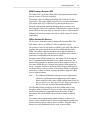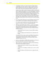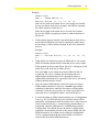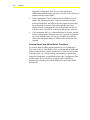
1
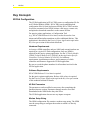
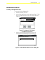
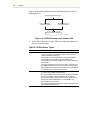
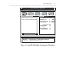
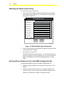
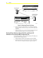
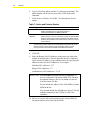
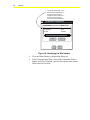
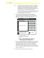
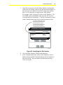
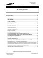
FANs 637.5, 1637.5 N2 Dial Section Issue Date 0400 APPLICATION NOTE N2 Dial Application Using N2 Dial ........................................................................................3 Introduction......................................................................................................... 3 Key Concepts...................................................................................................... 4 N2 Dial Configuration...................................................................................................... 4 Downloading with N2 Dial .............................................................................................. *6 Dial-in with N2 Dial ........................................................................................................ *7 Procedure Overview ........................................................................................*21 Detailed Procedures ......................................................................................... 23 Creating a Configuration File ........................................................................................ 23 Modifying a Parameter.................................................................................................. 26 Modifying the Modem Setup String ............................................................................... 28 Entering Phone Numbers in the Local NDM Configuration File ..................................... 28 Entering Phone Numbers, Remote Site IDs, and Remote N2 Addresses in the Remote NDM Configuration File......................................................................... *30 Deleting a Phone Number............................................................................................. 33 Saving the Configuration File ........................................................................................ 33 Downloading a Remote NDM and Remote N2 Devices via a Local NDM...................... 33 Downloading the Local NDM Using the Metasys Network............................................. 37 Downloading the Remote NDM and Remote N2 Devices Using the Metasys Network . 37 Downloading NDMs and Remote Devices from the Metasys Device Focus Window .... 38 Establishing a Connection Between Local and Remote NDMs ..................................... 38 Clearing an Alarm or Offline/Online Transition .............................................................. 42 *Indicates those sections where changes have occurred since the last printing. © 2000 Johnson Controls, Inc. Code No. LIT-6375150 www.johnsoncontrols.com 2 N2 Dial Troubleshooting ............................................................................................... 43 Downloading a Remote NDM and Remote N2 Devices via a Local NDM...................... 43 *Indicates those sections where changes have occurred since the last printing. N2 Dial Application 3 Using N2 Dial Introduction The N2 Dial application in HVAC PRO™ creates a configuration file for an N2 Dialer Module (NDM). This technical bulletin provides an overview of the N2 Dial application and includes procedures for creating configurations and downloading NDMs. This bulletin describes how to: • create a configuration file • modify a parameter • modify the modem setup string • enter phone numbers in the local NDM configuration file • enter phone numbers, remote site IDs, and remote N2 addresses in the remote NDM configuration file • delete a phone number • save the configuration file • download a remote NDM and remote N2 devices via a local NDM • download the local NDM using the Metasys® Network • download the remote NDM and remote N2 devices using the Metasys Network • download NDMs and remote devices from the Metasys device focus window • establish a connection between local and remote NDMs • clear an alarm or offline/online transition 4 N2 Dial Key Concepts N2 Dial Configuration The N2 Dial application in HVAC PRO creates a configuration file for an N2 Dialer Module (NDM). HVAC PRO can download/upload configuration files for local and remote NDMs. HVAC PRO can also be used to command a local NDM, initiate a dial-out to a remote site, and upload or download controllers on the remote N2 Bus. For passive printer applications, a Configuration Tool (e.g., HVAC PRO Release 6.00 or later) can also be used to clear alarms and offline/online transitions to allow additional dial-ins. This application is described in the Passive Printer Application topic in the Key Concepts section of this technical bulletin. Hardware Requirements At least two NDM controllers and two 9600 baud external modems are required for a typical N2 Dial configuration. Only one NDM is required for the passive printer application. See the N2 Dialer Module (NDM) Technical Bulletin (LIT-6363065) in the Application Specific Controllers Technical Manual (FAN 636.3) for hardware requirements, installation procedures, and a summary of which controllers and firmware support the N2 Dial application. Be sure to record the phone numbers for all modems involved in the N2 Dial application. Software Requirements HVAC PRO Release 5.10 or later is required. For the passive printer application, Release 6.00 or later is required. See the Passive Printer Application topic in the Key Concepts section of this technical bulletin for details. N2 Dial Parameters The parameters can be modified as necessary after completing the Question/Answer session. Parameter changes must be saved and downloaded to the NDM before they take effect. The N2 Dial application does not use any inputs or outputs. Modem Setup String The NDM configuration file contains a modem setup string. The NDM uses the setup string to configure the modem to which it is directly connected. N2 Dial Application 5 The NDM sends the modem setup string to the modem after the NDM is turned on. The NDM will also send the modem setup string if the modem is replaced or loses power for a period of time. The modem must accept the string before the NDM can resume normal operation. The modem setup string can be modified to meet modem requirements and phone line conditions. The appropriate modem setup string can be determined by reading the modem user’s manual. The default modem setup string is for a Hayes Smartmodem OPTIMA 96 modem or any Hayes-compatible 9600 baud modem. Refer to the N2 Dialer Module (NDM) Technical Bulletin (LIT-6363065) in the Application Specific Controllers Technical Manual (FAN 636.3) for a list of supported modems and the setup strings of other modems. The default modem setup string for the NDM is: AT &F ATE0L0N0Q1&C1&D3&Q0&S0 ATS0=1 S8=4 S11=50 S37=9 Table 1: Default Modem Setup String String Description AT Prefix to get the modem’s attention &F Recall factory settings as active configuration E0 Disable character echo L0 Low speaker volume N0 Lock in at speed specified in S37 Q1 Disable result codes &C1 DCD tracks the carrier &D3 DTR signals a hard-reset of modem &Q0 Communicate in asynchronous mode (local NDM only) &S0 DSR is always active S0 = 1 Answer after one ring S8 = 4 Comma duration set at 4 seconds S11 = 50 Used to increase dialing speed (tone only) S37 = 9 Connect only at 9600 baud DT Initiate a dial using the tone method Note: In this table, “0” indicates the number zero. 6 N2 Dial The &Q0 forces the local modem into asynchronous mode. The local and remote modem will communicate asynchronously, allowing faster modem turnaround and better N2 Bus performance. The FMS (Facility Management System) will provide the required error correction. IMPORTANT: Exclude the &Q0 parameter from the remote NDM. If this parameter is in the remote NDM’s setup string and the remote NDM dials a printer’s modem, nothing will be printed. Phone Numbers, Remote Site ID, and N2 Addresses for a Remote NDM Configuration File The remote site ID can be up to 31 characters and must match the Remote Site Name defined in the local NDM (case insensitive). A remote NDM contains the phone number of a local NDM and/or any printers to be called. The remote NDM can have up to three backup phone numbers, in case the first number is busy. The remote NDM will cycle through these numbers until it makes a connection, as described in the Dial-in with N2 Dial section of this document. The remote NDM configuration must also contain a complete and accurate list of all N2 addresses for all devices connected to the remote N2 Bus. Downloading with N2 Dial Downloading via Direct Access Direct Access means the PC with the Configuration Tool is accessing the local or remote NDM by directly connecting to the N2 Bus via a MM-CVT101. This standard download procedure is described in the Downloading Configurations and VMA Code chapter of the User’s Guide to HVAC PRO (LIT-6375040) in this manual. Direct Access is described in the Using Direct Access section of the Controller Access Technical Bulletin (LIT-6364013) in this manual. Make sure the local configuration is downloaded to the local NDM, and the remote configuration goes to the remote NDM. You will need the N2 address of the NDM to download to it. An NDM has an N2 address that is set with a hardware switch like other N2 devices. You cannot download an NDM using a Zone Bus. There is no Zone Bus access to an NDM. When downloading from a PC directly connected to a local or remote NDM (Direct Access), turn off the modem connected to the NDM before downloading. Be sure to turn on the modem after completing the procedure. N2 Dial Application 7 Downloading a Remote NDM and Remote N2 Devices via Auxiliary Access The Auxiliary Access feature allows the Configuration Tool to dial the remote NDM or connect vial null modem cable and perform the full range of commissioning functions (e.g., downloading, commissioning). Auxiliary Access requires HVAC PRO Release 6.00 or later or GX-9100 Release 4.0 or later. For details, see the Controller Access Technical Bulletin (LIT-6364013) in this manual. Downloading with the Metasys Network The Metasys Network provides the same download functions to the NDMs and the devices on the remote N2 Bus as it does to any device on a local N2 Bus. Once the NDM hardware has been mapped into the Metasys Network and the devices come online, they can be downloaded. In addition, HVAC PRO (Release 5.1 or later) can be used in conjunction with the Metasys Network to perform downloads. It is also possible to download the local and remote NDMs and their associated remote N2 devices through The Metasys Network without HVAC PRO. This can be done by dialing out to the remote facility and, once a connection is established, using the device’s focus window. Dial-in with N2 Dial Dial-in is the action taken by the remote NDM to establish a connection with the local NDM and the FMS. Dial-in is usually initiated by a Change-of-State (COS), alarm, or offline condition on the remote N2 Bus. The Dial In Control parameter on the remote NDM must be set to Enable for the remote NDM to dial in upon alarm or offline conditions. All devices on the remote N2 Bus will report their online status when a remote NDM dials in on alarm. The Metasys Companion™/Facilitator™ system will also print online advisories. 8 N2 Dial The local NDM configures the local modem to answer after one ring. The remote N2 devices appear as online to the FMS when communication is established. Alarms that occurred at the remote site will be logged by the FMS. Note: For additional information on passive printer applications (defined as applications where all primary and secondary phone numbers in the remote NDM configuration file are for passive devices), see the Passive Printer Application topic in the Key Concepts section of this technical bulletin. Dial-in from a Remote NDM The remote NDM is configured with one primary and three optional secondary phone numbers. The remote NDM dials in when an alarm, COS, or offline condition is detected and the Dial In Control is enabled. The remote NDM begins by dialing the primary number listed in the Action/Phone Number Configuration menu of the NDM’s configuration file. If the connection is not accomplished before the Modem Connect Time expires, the NDM hangs up, waits a period of the Dial Delay and begins dialing the primary number a second time. This process will continue until a connection is made or the number has tried four times without success. If the remote NDM fails to connect on the fourth try, it checks to see if additional phone numbers are defined. If additional phone numbers are defined, the remote NDM will dial the next number in the same manner as described above for the primary number. This process will continue until all of the defined numbers have been attempted. If no connection is made during this phase, the remote NDM starts the entire cycle again. This process is repeated until the connection is completed or the NDM has reached the number of retries specified in the configuration file’s Number of Retries parameter. N2 Dial Application 9 Once the connection is established, the following occurs: • If the phone number is configured as Passive, the remote NDM sends its 31-character Remote Site ID and N2 address, the N2 address of the remote device with the alarm, and a list of online devices. Then it disconnects. This allows the receiver of the call to identify the remote site that called in. The passive device is a printer. See the Passive Printer Application topic in the Key Concepts section of this technical bulletin for additional information on passive applications. • If the phone number is configured as Active, the Remote Site Name will not be sent and N2 Bus communications is expected. If N2 communication is not detected for a period of Idle Timeout, the remote NDM will transmit the Remote Site Name and an error message, hang up, and continue the dialing sequence. Take precautions to prevent excessive phone bills. Several ways to minimize phone bills are: 1. Never disable the Disconnect Delay parameter. 2. Make the Disconnect Delay parameter as small as possible. 3. Disable dial-in on known trouble sites. Disabling Dial-in The dial-in feature of a remote NDM can be disabled by setting the Dial In Control parameter to Disable. This will prevent the remote NDM from dialing in to report alarms or offline/online transitions in the remote N2 devices connected to it. (You may want to disable dial-in to eliminate nuisance calls from a known problem site.) If Dial In Control is not enabled, the remote NDM will dial-in only when it is reset by download, N2 command, or after a power-fail. Note: Some N2 devices that can reside on a remote N2 Bus should not be used to initiate dial-in. In fact, Dial In Control must be disabled if these types of devices are used on a remote N2 Bus. These devices are listed in Appendix A: Supported Devices and Firmware Revisions, under the column of the N2 Dialer Module (NDM) Technical Bulletin (LIT-6363065) in the Application Specific Controllers Technical Manual (FAN 636.3). 10 N2 Dial Dial-out Dial-out is the action taken by the local NDM to establish a connection with a remote site, usually due to a command from the FMS or from HVAC PRO. Dial-out can be used to monitor points on a remote N2 Bus or to change parameters in a remote NDM. A dial-out from HVAC PRO can also be used to clear alarms or offline/online transitions for passive applications. See the Passive Printer Application topic in the Key Concepts section of this bulletin for additional information on passive applications. The local NDM can be issued a dial command from its FMS. See Appendix B: Using Companion with an NDM in the N2 Dialer Module (NDM) Technical Bulletin (LIT-6363065) in the Application Specific Controllers Technical Manual (FAN 636.3) for Companion procedures. See Appendix C: Using Metasys CS Objects with an NDM in the N2 Dialer Module (NDM) Technical Bulletin (LIT-6363065) for CS (Control System) Object information. See Using Dial-Up with the NDM in the Operator’s Guide section of the Operator Workstation User’s Manual (FAN 634) for information on dialing out from an OWS. Dial Command Each remote site telephone number is associated with a value. Overriding the Dial Command parameter in a local NDM to a value from 1 to 50 will cause a dial-out to the remote site associated with the number. If the value of the Dial Command is overridden while connected to a remote site, the NDM will hang up with the current site and dial-out to the new site. If a remote site dials-in to the local NDM, a value of minus one (-1) is displayed for the Dial Command. Setting the Dial Command to 0 will cause a disconnect. If the NDM is given a Dial Command to dial a telephone number that is undefined, or if the NDM cannot make a connection within the allotted retries, the Dial Command will become 0 and the Connection Status will equal 4, for a failed connection. Number of Retries When the local NDM commands the modem to dial a number, the modem on the other end of the phone line may not answer. The local NDM will first wait a length of time equal to the Modem Connect Time. Then, if a connection has not been made, the modem will hang up and wait the Dial Delay time. N2 Dial Application 0 Retries 11 1 Retry Modem Connect Time 1st Call to Remote Site Number 1 Dial Delay No Answer from Remote Site Number 1 Modem Hangs Up 2nd Call to Remote Site Number 1 Repeat this sequence until a connection is made or the Number of Retries is reached. retry Figure 1: The Local NDM Retries a Dial The retry counter in the local NDM is now incremented to one. The modem redials the original phone number and waits for the Modem Connect Time to expire. If the remote modem still does not answer, the retry counter increments by one again. The modem will continue retrying until a connection is made or the Number of Retries parameter is reached. A value of 0 for the Number of Retries tells the local NDM to never stop redialing. Disconnect Delay A local NDM can be configured to disconnect with a remote NDM after a specified length of time. The two parameters that affect the disconnection of the call are the Disconnect Delay and the Disconnect Delay Control. The Disconnect Delay defines the amount of time that will expire before the local NDM will automatically hang up a connection. The Disconnect Delay Control allows the user to select whether to: • use the default time defined in the Disconnect Delay, • set the disconnect for 4 hours, or • never hang up The local NDM must contain a Disconnect Delay long enough to allow all remote N2 devices to come online and report alarms. If any alarms go unreported before the trunk disconnects, the remote NDM will detect those alarms and dial-in again. To use a Disconnect Delay, set the Disconnect Delay Control parameter to 0 and enter a value between 0 and 255 minutes for the Disconnect Delay parameter. Ten minutes is the default Disconnect Delay. If you want the local NDM to hang up four hours after connecting with the remote NDM, set the Disconnect Delay Control to 1. 12 N2 Dial If you do not want to use any Disconnect Delay, set the Disconnect Delay Control to 2. In this case, the automatic disconnect feature is disabled and you must disconnect by issuing a Dial Command of 0 to the local NDM. The Disconnect Delay Control is automatically reset to 0 whenever a connection is made. Monitoring the Modem Lights The modem lights and the Communication State parameters are two means of monitoring the connection status. The NDM configuration requires an external modem, and most external modems have indicator lights, so these lights are a good way to determine the status of the NDM connection. Table 2 contains a description of typical modem front panel indicator lights. Table 2: Modem Indicator Lights Light Description HS High Speed AA Auto Answer, on when the modem is set to answer incoming calls CD Carrier Detect, the modem is receiving a valid data carrier signal from the sending modem OH Off Hook RD Receive Data SD Send Data TR Terminal Ready MR Modem Ready The following figures indicate which lights should be on for each phase of NDM operation using a Hayes Smartmodem OPTIMA 96 modem. HS AA CD OH RD SD TR MR MODEM1 Figure 2: Modem is On, No Dial Initiated HS AA CD OH RD SD TR MR MODEM2 Figure 3: Modem is Initiating a Dial N2 Dial Application HS AA CD OH RD SD TR MR MODEM3 Figure 4: Modem Connection is Made HS AA CD OH RD SD TR MR MODEM4 Figure 5: Uploading from a Remote NDM HS AA CD OH RD SD TR MR MODEM5 Figure 6: Downloading to a Remote NDM HS AA CD OH RD SD TR MR MODEM6 Figure 7: Controller Information for Remote N2 Devices 13 14 N2 Dial Communication State Parameters The Communication State parameters are another way to monitor NDM communications. The values of the Communication State parameters will appear as asterisks unless you are in Commissioning mode with a local NDM. Table 3 indicates the Communication State parameters for each phase of NDM operation. Table 3: Communication State Parameters NDM Activity Connection Status Dial Command Modem is On, No Dial Initiated 0 0 Modem is Initiating a Dial 1 1-50* Modem Connection is Made 2 1-50* Phone is Busy, No Connection 3 1-50* No Connection, Retries Exhausted 4 Downloading to a Remote NDM 2 1-50* Uploading from a Remote NDM 2 1-50* Obtaining Remote Controller Information 2 1-50* Remote NDM Dials in to a Local NDM -1 NA * Dial Command should equal the site number of the site being dialed, from 1-50, as shown in the Phone Number Configuration information from the Action menu. Online and Offline Polling A remote NDM controls the communications on the remote N2 Bus when the modem is inactive. The remote NDM polls all N2 devices. The alarm and COS information is preserved for the FMS until the telephone connection is established. In an active application, only the FMS can “clear” the alarm condition or COS. In a passive application, a Configuration Tool (e.g., HVAC PRO) must clear the alarm condition. NDM Firmware Revision D01 and Later The remote NDM polls only the device addresses defined in its configuration. These are the addresses listed in the Remote N2 Device Address field in the N2 Dial Site Configuration dialog box. The NDM builds an online/offline table containing these listed device addresses. The NDM polls the listed device addresses in consecutive order. N2 Dial Application 15 NDM Firmware Revision D00 The Online Poll Count and Offline Poll Count parameters determine how the remote N2 devices are polled. The default values for Online and Offline Poll Count are 20 and 5, respectively. The remote NDM will poll 20 devices it has determined to be online, then poll 5 offline devices, then repeat the process. The poll count defaults should be adequate for most remote sites. Increasing the Online Poll Count may reduce the time required for the remote NDM to detect an alarm in a remote N2 device. Increasing the Offline Poll Count may improve the rate at which remote N2 devices come online. Offline Remote N2 Devices N2 devices are normally scanned continuously from the FMS. The FMS marks a device as offline if it fails to respond to a poll. The remote N2 devices will appear as offline to the FMS when there is no phone line connection between the local NDM and the remote NDM. This offline condition is not always an alarm condition. A problem exists only if the remote devices are offline while a phone connection is established with the remote NDM. From the remote NDM’s perspective, the remote N2 devices do not lose N2 communications when there is no phone connection. The remote NDM continues to poll the devices on the remote N2 Bus. If the remote NDM does see a change in the online/offline status of a device, it initiates a dial-in to the local NDM. Remote NDM activity can be tracked by a passive printer. If the remote NDM is configured to dial in to a printer on alarm, examine the printer output for which devices reported alarms. Note: For additional information on passive printer applications (defined as applications where all primary and secondary phone numbers in the remote NDM configuration file are for passive devices), see the Passive Printer Application topic in the Key Concepts section of this technical bulletin. The Disconnect Delay parameter in the local NDM must be long enough to allow all remote N2 devices to come online and report alarms. If any alarms go unreported before the remote N2 Bus disconnects, the remote NDM will detect those alarms and dial in again. Use caution when implementing standard features on remote N2 devices. Some standard features, such as scheduling and point history, cannot function properly when a device is offline. Therefore, these features are not recommended for use with a remote NDM. 16 N2 Dial The N2 communication status is used by a controller to enable standalone operation, that is, to change the occupancy point at a specified time. Note: Standalone operation of remote N2 devices is disabled by the remote NDM. Offline scheduling of remote N2 devices should never be activated. Idle Timeout The remote NDM contains an Idle Timeout parameter. It is used when the remote NDM dials in to an Active device. The remote NDM will begin a timer for the Idle Timeout parameter when it connects with the local NDM. The remote NDM will watch for N2 traffic. If no N2 traffic occurs for a length of time equal to the Idle Timeout parameter, three things will occur in succession: 1. The remote NDM will send a remote site ID and an error message. 2. The remote NDM will hang up. 3. The remote NDM will dial the next phone number from the Action/Phone Number Configuration list. Disconnect Control The local NDM is responsible for disconnect control, regardless of which NDM initiated the call. The connection will be maintained until one of three things occur: • The Dial Command is overridden to a value of zero. This causes the modem to disconnect. • A different number is entered for the Dial Command. This causes the modem to disconnect and dial the new number. • The Disconnect Delay Control is set to 0 and the Disconnect Delay Timer expires and causes the disconnection. The disconnect timer is kept in the local NDM. The timer is started when the connection is established. The local NDM monitors the disconnect timer. The local NDM will break the connection when the timer expires. The Disconnect Delay Timer may be disabled by setting the Disconnect Delay Control equal to 2. Set the Disconnect Delay Control to 2 if you do not want to use any Disconnect Delay. If the automatic disconnect feature is disabled, you must disconnect by issuing a Dial Command of 0 to the local NDM. N2 Dial Application Notes: 17 The potential exists for excessive phone bills when the Disconnect Delay Control is overridden to 2. The local NDM must contain a Disconnect Delay at least long enough to allow all remote N2 devices to come online and report alarms. If any alarms go unreported before the trunk disconnects, the remote NDM will detect those alarms and dial in again. Passive Printer Application A passive printer application is comprised of a remote NDM, remote devices, and printers used for alarm notification. The passive printer application does not have a local NDM connected to an FMS headend. Instead, the remote NDM dials only passive printers to report alarms (changes of state) and offline/online transitions. To set up a passive printer application, all primary and secondary phone numbers in a remote NDM configuration must be defined as passive devices (printers). In a passive printer application, reported alarms and offline/online transitions must be cleared using a Configuration Tool (such as HVAC PRO). The NDM will not dial in to report subsequent alarms and offline/online transitions for a device until the original alarm or offline/online transition is cleared. Note: For information on setting up modems for this application, see Passive Printer Modem Setup in the N2 Dialer Module (NDM) Technical Bulletin in the Application Specific Controllers Technical Manual (FAN 636.3). The passive printer application works as follows: • The NDM firmware must be Revision D01 or later. • 2K controllers involved in the passive printer application must be upgraded to HVAC PRO Release 6.00 (so that alarms and offline/online transitions can be cleared via HVAC PRO). The 2K controllers are designated by a -0 suffix (e.g., AS-UNT111-0). • All primary and secondary phone numbers in the remote NDM configuration must be defined as passive. 18 N2 Dial • For changes-of-state to be reported for points, alarms must be enabled and alarm limits (analog) or alarm conditions (binary) must be defined for the points in a Configuration Tool such as HVAC PRO. If the point is defined for alarms, and the point transitions into alarm or back to normal, the NDM will initiate the dial in sequence and report the COS. For analog points, if warning limits are defined in addition to alarm limits, the NDM will also dial in to report value transitions into warning and back to normal. Conversely, if there are no alarm limits or alarm conditions defined, value or state changes will not cause the NDM to dial in. Note that if only warning limits are defined and not alarm limits, the NDM will not dial in to report values that exceed the warning limits. • In a passive printer application, when attempting connection, the remote NDM uses its configured communication parameters (e.g., dial in control, number of retries, dial delay, and modem connect time) just as it would in a standard application. • When the remote NDM comes online (e.g., after reset or power up), it dials the passive printer to report its online status and the online status of connected N2 devices. When connection is established, the printer prints the following information and the NDM disconnects: - remote site ID and N2 address of remote NDM initiating connection - list of N2 addresses of all online devices connected to the NDM If a remote N2 device has an alarm, the NDM will immediately dial in again to report the alarm condition. At this point, a Configuration Tool must be used to clear the alarm to allow additional reports to be sent. • In the case of an alarm or offline/online transition in a N2 device, the remote NDM dials in to the local passive printer. When connection is established, the printer prints the following information and the NDM disconnects: - remote site ID and N2 address of remote NDM initiating connection - Alarm Device: N2 address of offline device or device with alarm - list of N2 addresses of all online devices connected to the NDM N2 Dial Application 19 Example: Remote West NDM 3 - ALARM DEVICE 15 Devices online: 11, 12, 13, 14, 16 If the device listed as the alarm device is not in the list of online devices (as shown in the above example), the NDM is reporting the offline transition of this device. If the device listed as the alarm device is in the list of online devices, the NDM is reporting an alarm or online transition for this device. • If the printout does not include a line indicating an alarm device, this means the NDM has reset and is reporting its online status, not an alarm or offline/online transition in one of its connected devices. Example: • Remote West NDM 3 - Devices online: 11, 12, 13, 14, 15, 16 If the dial-in was initiated to report an offline device, the remote NDM will initiate another dial-in when that device comes online. In the printout for this second dial-in, the device will appear as the alarm device and in the list of online devices. This is the only case in which the remote NDM will dial in a second time for a device without first having the alarm or offline/online transition cleared. For subsequent alarms or offline/online transitions to be reported for this device, the initial offline transition must be cleared. • Once the remote NDM initiates a dial-in to report an alarm or offline/online transition for a device, it cannot report another condition for that device until the first alarm or offline/online transition is cleared (except in the case of the second dial-in to report the device coming back online, as described above). • To clear the alarm or offline/online transition, use a Configuration Tool (e.g., HVAC PRO Release 6.00) to dial the remote NDM and initiate communication with the remote device. Once any sort of dial communication (e.g., commissioning, downloading, or performing controller information) is established between the Configuration Tool and the device, the alarm or offline/online transition is automatically cleared by the remote NDM, after the NDM disconnects. If an alarm occurs while the Configuration Tool is communicating with the remote NDM, it will also be cleared after the remote NDM disconnects. 20 N2 Dial Using the Configuration Tool, you can clear alarms and offline/online transitions for one device at a time or for all devices connected to the remote NDM. • If the Configuration Tool is connected to the NDM to clear an alarm COS, but the point status cannot be returned to normal before disconnection, the NDM will dial in again to report when the point returns to normal. This report will then have to be cleared with the Configuration Tool. In the printout, the device with the normal COS will be indicated as the ALARM DEVICE. • If all connections fail (e.g., exhausted number of retries), and the alarm or offline/online transition was never reported or printed at any of the defined passive devices, the condition must still be cleared for subsequent alarms or offline/online transitions to be reported. Clearing Alarms and Offline/Online Transitions To clear an alarm or offline/online transition, use a Configuration Tool, such as HVAC PRO Release 6.00, to dial the remote NDM and initiate communication with the remote device. Once any sort of dial communication (e.g., commissioning, downloading, or performing controller information) is established between the Configuration Tool and the remote device, the alarm or offline/online transition is automatically cleared by the remote NDM (once the remote NDM disconnects). N2 Dial Application 21 Procedure Overview Table 4: Using N2 Dial To Do This Follow These Steps: Create a Configuration File From the File menu, select New. Select N2 Dial Applications from the Application Group. Click on OK to begin the Question/Answer session. Select the N2 Dial device type. Modify a Parameter Display the parameters in a list box. Double-click on a parameter. Modify the long name, short name, value, or units. Click on OK. Modify the Modem Setup String Open an N2 Dial configuration file. Open the Action menu and select Modem Setup Strings. Tab to the appropriate field and enter a modem setup string. Click on OK. Enter Phone Numbers in the Local NDM Configuration File Open the Action menu and select Phone Number Configuration. Select Unused to add a site name or select an existing site name. Click on Modify. Type in a remote site name. Type in a remote site phone number. Click on OK. Save the file and download it to the local NDM. Enter Phone Numbers, Remote Site IDs, and Remote N2 Addresses in the Remote NDM Configuration File Open the Action menu, and select Phone Number Configuration. Type in the remote site name. Select Unused to add a site name, or select a site name to modify an existing entry. Click Modify. Type in a local site name. Type in a local site phone number. Select Active or Passive. Click OK. Enter the Remote Site N2 addresses. Save the file and download it to the remote NDM. Delete a Phone Number Open the Action menu and select Phone Number Configuration. Highlight the site name and select Delete. Click on OK. Save the Configuration File From the File menu, select Save As. Click on OK. Enter a filename and click on OK. Download a Remote NDM and Remote N2 Devices via a Local NDM Connect a computer running HVAC PRO to a local NDM. Download the local NDM with the local N2 Dial configuration file. From the Commission menu, choose Configuration in Controller and provide the N2 address of the local NDM. Click OK. Open the Action menu and select Phone Number Configuration. Identify the number of the remote site to be dialed. Close the Phone Number Configuration dialog box. In the Communication State section of the Parameters list box, double-click Dial Command, enter the site number of the remote NDM, and click Override. Watch the Connection Status to verify connection. Once Connection Status is 2, override the Disconnect Delay Control to a value of 1. Exit Commissioning mode with the local NDM after the connection has been made. Download or commission the desired controllers. When finished downloading or commissioning the remote devices, enter Commissioning mode with the local NDM again. Double-click Dial Command and override the value to 0. Exit Commissioning mode. Download the Local NDM Using the Metasys Network With the Metasys software running in the background, open the local NDM configuration file to download in HVAC PRO. Select Current Configuration from the Download menu. Select an NC. Highlight the local NDM to download, and click OK to start the download. Download the Remote NDM and Remote N2 Devices Using the Metasys Network Select N2 Dial from the Network Map Setup menu. Highlight the remote site. Select Dial from the Action menu and wait until the connection is established. In HVAC PRO, open the configuration file to download. Select Current Configuration from the Download menu. Select an NC. Highlight the controller to download, and click OK. After the download is complete, return to the Metasys software N2 Dial Summary to disconnect. Continued on next page . . . 22 N2 Dial To Do This (Cont.) Follow These Steps: Download NDMs and Remote Devices from the Metasys Device Focus Window Select N2 Dial from the Network Map Setup menu. Highlight the remote site. Select Dial from the Action menu. Display the remote device focus window, and select Download Controller from the Action menu. Establish a Connection Between Local and Remote NDMs Connect a computer running HVAC PRO to a local NDM. From the Commission menu, choose Configuration in Controller and provide the N2 address of the local NDM. Click on OK. Open the Action menu and select Phone Number Configuration. Identify the number of the remote site to be dialed. Close the Phone Number Configuration dialog box. In the Communication State section of the Parameters list box, double-click on the Dial Command and enter the site number of the remote NDM. Click on Override. Watch the Connection Status. Once Connection Status is 2, override the Disconnect Delay Control to a value of 1. Exit Commissioning mode with the local NDM after the connection has been made. When finished downloading or commissioning the remote devices, enter Commissioning mode with the local NDM again. Double-click Dial Command and override the value to 0. Exit Commissioning mode. Clear an Alarm or Offline/Online Transition Dial the remote NDM. Once the connection is established, commission the specific device with the alarm. Once the Configuration Tool communicates with the device and disconnects from the NDM, the alarm or offline/online transition is automatically cleared. To clear the alarm without commissioning the device, use the Controller Information option from the Action menu. After selecting Controller Information from the Action menu and specifying the device or devices, wait for the controller information to be processed. N2 Dial Application 23 Detailed Procedures Creating a Configuration File To create an N2 Dial configuration file: 1. From the File menu, select New. 2. Select N2 Dial Applications from the Application Group. N2 Dial Module Configuration appears as the only available application (Figure 8). File New / Application Selection Application Group: N2 Dial Applications Applications: N2 Dial Module Configuration ual Duct OK Cancel NEWN2AP Figure 8: Creating an N2 Dial Module Configuration Dialog Box 3. Click on OK to begin the Question/Answer session. The Question/Answer session dialog box appears (Figure 9). Question/Answer Session Select the N2 Dial device type: Local - On an N2 of a supervisory system Remote - On an N2 with remote devices N2PROQA Figure 9: N2 Dial Question/Answer Session Dialog Box 24 N2 Dial Figure 10 shows the complete question and answer path for the N2 Dial application. Select the N2 Dial device type: Local - On an N2 of a supervisory system Remote - On an N2 with remote devices Go to Parameter Definition n2dialqa Figure 10: N2 Dial Question and Answer Path 4. Select the N2 Dial device type. Table 5 provides descriptions of the two available types. Table 5: N2 Dial Device Types Device Type Description Local NDM A configuration file for a local NDM is created by answering “Local – On an N2 of a supervisory system” when asked to “Select the N2 Dial device type.” A local NDM is connected directly to a Facility Management System (FMS) via the N2 Bus. The local NDM can be commanded to dial a remote NDM and can answer calls from a remote NDM. The HVAC PRO main screen shown in Figure 11 appears for a local NDM configuration file. The values of the Communication State parameters will appear as asterisks unless HVAC PRO is in Commissioning mode with the local NDM. Remote NDM Choose the “Remote - On an N2 with remote devices” answer to create a remote NDM configuration file. The remote NDM is located at the remote site and is not directly connected to a FMS. The remote NDM scans the remote devices for Changes-of-State (COS) or alarms. When either is detected, the remote NDM dials in to a local NDM or to a passive device (e.g., a printer). The HVAC PRO main screen shown in Figure 12 appears for a remote NDM configuration file. 25 N2 Dial Application Johnson Controls - HVAC PRO File Download Upload Commission INPUTS Q/A OUTPUTS Action Options Help PARAMS SIDELOOP Current Question/Answer Path Parameters Select the N2 Dial device type: Local - On an N2 of a supervisory system Communication Parameters Number of Retries 3 Times Dial Delay 4 Minute Modem Connect Time 60 Second Disconnect Delay 10 Minute Communication State Connection Status ****** Dial Command ****** Disconnect Delay Co... ****** Remote NDM Address ****** Date: 09/20/95 Device Type: Application: Filename: Time: 1:00:00 PM N2 Dial Module - NDM N2 Dial Applications - N2 Dial Module Configuration C:\WINPRO\FILES\N2LOCAL.CFG N2LOCAL Figure 11: Local N2 Dial Module Configuration Dialog Box 26 N2 Dial Johnson Controls - HVAC PRO File Download Upload Commission Action Q/A INPUTS OUTPUTS Options Help PARAMS SIDELOOP Current Question/Answer Path Parameters Select the N2 Dial device type: Remote - On an N2 with remote devices Communication Parameters Number of Retries 3 Times Dial Delay 4 Minute Modem Connect Time 60 Second Dial In Control Enable Idle Timeout 5 Minute Polling Paramters Online Poll Count 20 Offline Poll Count 5 Date: 05/20/94 Device Type: Application: Filename: Time: 1:00:00 PM N2 Dial Module - NDM N2 Dial Applications - N2 Dial Module Configuration C:\WINPRO\FILES\N2REMOTE.CFG n2remote Figure 12: Remote N2 Dial Dialog Box Modifying a Parameter To modify a parameter: 1. Display the parameters in a list box. 2. Double-click on a parameter. 3. Modify the long name, short name, value, or units. See Table 6 for a description of each parameter. Note: 4. Not all of the parameters shown in Table 6 are contained in a local NDM or in a remote NDM. The Usage column indicates whether a parameter is used in a local NDM, a remote NDM, or both. Press Enter or click on OK. N2 Dial Application 27 Table 6: NDM Parameters Parameter Name Description Default Maximum Usage Number of Retries Number of retries before a dial attempt ceases 3 Times 100 Both Dial Delay Number of minutes to delay before retrying a dial operation 4 Minutes 30 Both Modem Connect Time Time required for the modem to make a connection 60 Seconds 255 Both Connection Status 0 = Idle 1 = Dialing 2 = Connected 3 = Retry 4 = Fail 0 Dial Command -1 = Remote Connection 0 = Hang Up 1-50 = Site Number 0 50 Local Disconnect Delay Number of minutes to wait before disconnecting a call 10 Minutes 255 Local Disconnect Delay Control Determines whether the Disconnect Delay is used. 0 = Use Disconnect Delay 1 = 4 Hour Delay 2 = Never Hang Up 0 2 Local Remote NDM Address N2 Address of the Remote NDM NA 255 Local Dial In Control Enable = Alarm or COS initiates Dial-in from Remote NDM Disable = Remote NDM will not Dial-in on Alarm or COS 0 Enable Idle Timeout After a Dial-in, the remote NDM will hang up if no N2 communication is detected during the idle timeout. 5 Minutes 255 Remote Online Poll Count* Number of online devices to poll before offline devices 20 255 Remote Offline Poll Count* Number of offline devices to poll before online devices 5 255 Remote * These parameters are used on NDMs with D00 firmware only. Local Remote 28 N2 Dial Modifying the Modem Setup String To modify the modem setup string: 1. Open an N2 Dial configuration file. Open the Action menu and select Modem Setup Strings. The N2 Dial Modem Setup dialog box appears (Figure 13). N2 Dial Modem Setup Modem Setup Strings Setup String 1 AT&F Setup String 2 ATE0L0N0Q1&C1&D3&Q0&S0 Setup String 3 ATS0=1 S8 = 4 S11= 50 S37=9 Setup String 4 Setup String 5 Setup String 6 Setup String 7 Prefix to Dialing ATDT OK Cancel N2MODEM Figure 13: N2 Dial Modem Setup Dialog Box 2. Tab to the appropriate field and enter a modem setup string. Refer to the modem user’s manual. 3. Press Enter or click on OK. The NDM sends all of Setup Strings 1-7 to the modem when the modem is turned on. Those strings that are not used should be left blank. The NDM uses the Prefix to Dialing whenever a call is made. Entering Phone Numbers in the Local NDM Configuration File To enter phone numbers in the local NDM configuration file: 1. Obtain the phone numbers for all modems located at the remote NDMs. 2. Obtain the exact remote site names for all remote NDMs. The remote site name is stored in the remote NDM configuration file, under the Action/Phone Number Configuration menu. N2 Dial Application 3. 29 Open the Action menu and select Phone Number Configuration. A dialog box similar to Figure 14 will appear. N2 Dial Site Configuration # Site Name Phone Number 1) JCI Tower 2) East Wing Unused 555-5416 5328 Available Modify Delete OK Cancel N2CONFIG Figure 14: N2 Dial Site Configuration Dialog Box 4. Select Unused to add a site name. To modify any existing site name which may already have been entered, select the site name. Click on Modify. The Modify Remote Site dialog box appears (Figure 15). Modify Remote Site Remote Site Name: JCI Tower Phone Number: 555-5416555-5416 OK Cancel MRSDB Figure 15: Modify Remote Site Dialog Box 5. Type in a remote site name using 31 characters or less. Note: The remote site name in the local NDM must exactly match (case insensitive) the remote site name listed in the remote NDM, under the Action/Phone Number Configuration menu. Failure to do so will disable certain functions on the FMS. (See Figure 16.) 30 N2 Dial N2 Dial Site Configuration Remote Site Name in the local NDM ... # Site Name Phone Number 1) JCI Tower 2) East Wing Unused 555-5416 5328 Available ... must exactly match the Remote Site Name in the remote NDM N2 Dial Site Configuration Remote Site Name: JCI Tower # Site Name Type Phone Number 1) Local NDM#1 2) Main Printer 3) Tony's Printer Unused Active 555-4708 Passive 555-2183 Passive 555-2345 Available SITENAM Figure 16: Matching Remote Site Names 6. Type in a remote site phone number of 31 characters maximum. The phone number will be used as part of the ATDT modem dial command. 7. Click on OK. Be sure to save the file and download it to the local NDM for the phone numbers to be stored in the NDM. Entering Phone Numbers, Remote Site IDs, and Remote N2 Addresses in the Remote NDM Configuration File To enter phone numbers, remote site IDs, and remote N2 addresses in the Remote NDM Configuration File: 1. Obtain the phone numbers of the modems at the local NDMs. 2. Open the Action menu, and select Phone Number Configuration. The N2 Dial Site Configuration dialog box appears (Figure 17). N2 Dial Application 31 N2 Dial Site Configuration Remote Site Name: JCI Tower # Site Name Type Phone Number 1) Local NDM#1 2) Main Printer 3) Tony's Printer Unused Active Passive Passive 555-4708 555-2183 555-2345 Available Modify Delete Remote N2 Device Addresses: OK 1..3, 6..8 Cancel 2CONFI Figure 17: Local Site Phone Numbers Stored in a Remote NDM 3. Type in the remote site name, using a maximum of 31 characters. The remote site name is an identifier so the local NDM or passive device can identify which remote NDM initiated the dial-in. For instance, if the remote NDM dials out to a printer on a COS or alarm, it will print its remote site name. The remote site name is saved as part of the configuration file. Note: 4. For a given site, the remote site name in the remote NDM must exactly match (case insensitive) the site name listed in the Action/Phone Number Configuration menu of the local NDM. Certain functions will not work from the FMS if the site names do not match. Select Unused to add a site name, or select a site name to modify an existing entry. Click Modify. The Modify Local Site dialog box appears (Figure 18). Modify Local Site Local Site Name: Local NDM #1 Phone Number: 555-4708555-5416 Active Passive OK Cancel MLSDB Figure 18: Modify Local Site Dialog Box 5. Type in a local site name (31 characters maximum). 32 N2 Dial 6. Type in a local site phone number (31 characters maximum). The phone number will be used as part of the ATDT modem dial command. 7. Select Active or Passive. See Table 7 for descriptions of each option. Table 7: Active and Passive Devices Device Type Description Active devices Active devices are devices that control communication on the N2 Bus. Examples are PC and Panel versions of Companion/Facilitator and Metasys Network. Passive devices Passive devices are non-N2 devices, such as printers. For passive devices, once the connection is made, the remote NDM sends an ASCII string containing its Remote Site Name and N2 address, the N2 address of the alarm device, and a list of online remote devices. Note: For passive printer applications (defined as applications where all primary and secondary phone numbers in the remote NDM configuration file are for passive devices), see the Passive Printer Application topic in the Key Concepts section of this technical bulletin for additional information. 8. Click OK. 9. Enter the Remote Site N2 addresses in the space provided at the bottom of the dialog box. This list identifies the active addresses on the remote N2 trunk. Use the standard syntax for specifying N2 addresses and verify the N2 addresses. For example, Individual N2 Addresses: 1,3,7 Range of N2 Addresses: 1..3 Combination of N2 Addresses: 1..3,6..8 IMPORTANT: This field must correctly list all N2 addresses for devices connected to the remote NDM. This list must be updated whenever devices are added or removed from the remote N2 Bus. Do not include the address of the local NDM or remote NDM in the list. Also, do not include the N2 addresses of any XT-9100 modules connected to the XT Bus of a DX-9100 controller. 10. Be sure to save the file and download it to the remote NDM for the phone numbers to be stored in the NDM. N2 Dial Application 33 Deleting a Phone Number To delete a phone number: 1. Open the Action menu and select Phone Number Configuration. 2. Highlight the site name and select Delete. Click on OK. Saving the Configuration File To save the configuration file: 1. From the File menu, select Save As. 2. The device type defaults to N2 Dialer Module and the target device defaults to NDM. Click on OK or press Enter. 3. Enter a filename and click on OK or press Enter. Downloading a Remote NDM and Remote N2 Devices via a Local NDM To download a remote NDM and remote N2 device via a local NDM: 1. Connect a computer running HVAC PRO to a local NDM using a MM-CVT101-0. 2. Download the local NDM with the local N2 Dial configuration file. This configuration should contain the phone number of the remote site to be downloaded. 3. From the Commission menu, choose Configuration in Controller and provide the N2 address of the local NDM. Click OK. HVAC PRO may also ask to read the configuration from the file; click Yes. HVAC PRO should now be in Commissioning mode with the local NDM. 4. Open the Action menu and select Phone Number Configuration. Look at the first column on the far left and identify the number of the remote site to be dialed. HVAC PRO assigns a site number from 1 to 50 in the order in which the sites were defined. For example, Figure 19 shows JCI Tower as Site Number 1. The local NDM can be commanded to dial out to the JCI Tower by overriding the Dial Command to 1. The Dial Command is located in the Communication State section of the Parameters list box. 34 N2 Dial JCI Tower is Site Number 1, and the East Wing is Site Number 2. To dial out to the JCI Tower, override the Dial Command to 1. To dial out to the East Wing, override the Dial Command to 2. N2 Dial Site Configuration # Site Name Phone Number 1) JCI Tower 2) East Wing Unused 555-5416 5328 Available Modify OK Delete Cancel n2confgb Figure 19: Identifying the Site Number 5. Close the Phone Number Configuration dialog box. 6. In the Communication State section of the Parameters list box, double-click Dial Command, enter the site number of the remote NDM, and click Override. 35 N2 Dial Application While in Commissioning mode with the local NDM ... Johnson Controls - HVAC PRO - Commissioning Mode File Download Upload Commission Action Options Help Q/A INPUTS OUTPUTS PARAMS SIDELOOP Current Question/Answer Path Parameters Select the N2 Dial device type: Local - On an N2 of a supervisory system Communication Parameters Number of Retries 3 Times Dial Delay 4 Minute Modem Connect Time 60 Second Disconnect Delay 10 Minute Communication State Connection Status 2 Dial Command 1 Disconnect Delay Co... 1 Remote NDM Address 8 ... set the Disconnect Delay Control to 1, override the Dial Command to the appropriate Site Number, and monitor the Connection Status. connect connect Figure 20: Communication State Parameters Screen Watch the Connection Status to verify connection (a value of 2 means connection is made). It should change in the following sequence: 7. 0 The modem is idle. 1 The modem is dialing out to the remote NDM. 2 A connection has been made between the local NDM and the remote NDM. Once Connection Status is 2, override the Disconnect Delay Control to a value of 1. This sets the automatic disconnect delay timer in the local NDM to four hours. The local NDM will not hang up the line (for four hours) while you are downloading or commissioning the remote devices. 36 N2 Dial Note: 8. Overriding the Disconnect Delay Control to 2 disables the automatic disconnect delay feature. In this case, the phone connection will be maintained indefinitely until the Dial Command point is manually overridden to hang up the call. Care should be used when disabling the automatic disconnect function, especially on long distance phone calls, as there is a potential for large phone bills if the user does not manually hang up the connection. Exit Commissioning mode with the local NDM after the connection has been made. Do not reset the controller upon exiting commissioning or the modem will hang up (Figure 21). Retain the overrides to non-configurable parameters. Commission Exit Configuration Changes Hardware Point Attributes Exit/No Change None... Exit/Save Changes Parameter Value Changes Remove Override None... Cancel View Details>> Save Overrides to Controller Save Controller Values to File Reset Controller EXIT13 Do not reset the controller when exiting Commissioning mode with an NDM. Figure 21: Exit Commissioning without Resetting the Controller Screen 9. If you are unsure of which remote N2 addresses are connected to the remote NDM, upload the remote NDM’s configuration file. For upload procedures, see the Uploading and Upgrading Configurations chapter of the User’s Guide to HVAC PRO (LIT-6375040) in this manual. Open the Action menu, and select the Phone Number Configuration option. Scan the list of Remote N2 Device Addresses. 10. Download or commission the desired controllers. N2 Dial Application 37 11. When finished downloading or commissioning the remote devices, enter Commissioning mode with the local NDM again. Double-click Dial Command and override the value to 0. This will issue a hang-up command to the local NDM. The remote NDM will also hang up once the remote modem loses the Carrier Detect. 12. Exit commissioning mode, retaining overrides to non-configurable parameters. Downloading the Local NDM Using the Metasys Network To download the local NDM using the Metasys Network: 1. From the Metasys Network, exit to Program Manager while keeping the Metasys software running in the background. This will allow the necessary interaction between the two programs. 2. In HVAC PRO, open the local NDM configuration file to download. 3. Select Current Configuration from the Download menu. This brings up a window displaying the NCs (Network Control Modules--e.g., NCM300s and NCM200s) on the network. 4. Select an NC. This displays a list of controllers connected to that NC. 5. Highlight the local NDM to download, and click OK to start the download. After the download is complete, the NDM resets, which causes the device to go offline. After the reset is complete, it will report back online and that the download sequence has been completed. Downloading the Remote NDM and Remote N2 Devices Using the Metasys Network To download the remote NDM and remote N2 devices using the Metasys Network: 1. Select N2 Dial from the Network Map Setup menu. This displays the N2 Dial Summary. 2. Highlight the remote site. 3. Select Dial from the Action menu and wait until the connection is established. After the communication link is established between the local and remote NDM, and the remote devices come online, the devices can be downloaded. 4. Exit to Program Manager while keeping Metasys software running. 5. In HVAC PRO, open the configuration file to download. 38 N2 Dial 6. Select Current Configuration from the Download menu. This brings up a window displaying the NCs on the network. 7. Select an NC. This displays a list of controllers connected to that NC. 8. Highlight the controller to download, and click OK. Notes: After the remote NDM is downloaded, it hangs up, resets, and then dials back to verify a successful download. If you are going to download other remote devices after downloading the NDM itself, start again with Step 1 to avoid a disconnection. 9. After the download is complete, return to the Metasys N2 Dial Summary to disconnect. Downloading NDMs and Remote Devices from the Metasys Device Focus Window To download NDMs and remote devices from the Metasys Device Focus window: 1. Select N2 Dial from the Network Map Setup menu. This displays the N2 Dial Summary. 2. Highlight the remote site. 3. Select Dial from the Action menu. 4. After the communication link is established between the local and remote NDM, and the remote devices come online, the devices can be downloaded. To do so, display the remote device focus window, and select Download Controller from the Action menu. Note: After the remote NDM is downloaded, it hangs up, resets, and then dials back to verify a successful download. Establishing a Connection Between Local and Remote NDMs To establish a connection between local and remote NDMs: 1. Connect a computer running HVAC PRO to a local NDM using an MM-CVT101-0. 2. From the Commission menu, choose Configuration in Controller and provide the N2 address of the local NDM. Click on OK. HVAC PRO may also ask to read the configuration from the file, click on Yes. HVAC PRO should now be in Commissioning mode with the local NDM. N2 Dial Application 3. 39 Open the Action menu and select Phone Number Configuration. Look at the first column on the far left and identify the number of the remote site to be dialed. HVAC PRO assigns a site number from 1 to 50 in the order in which the sites were defined. For example, Figure 22 shows JCI Tower as Site Number 1. The local NDM can be commanded to dial out to the JCI Tower by overriding the Dial Command to 1. The Dial Command is located in the Communication State section of the Parameters list box. JCI Tower is Site Number 1, and the East Wing is Site Number 2. To dial out to the JCI Tower, override the Dial Command to 1. To dial out to the East Wing, override the Dial Command to 2. N2 Dial Site Configuration # Site Name Phone Number 1) JCI Tower 2) East Wing Unused 555-5416 5328 Available Modify OK Delete Cancel n2confgb Figure 22: Identifying the Site Number 4. Close the Phone Number Configuration dialog box. 5. In the Communication State section of the Parameters list box, double-click on the Dial Command and enter the site number of the remote NDM. The site number was determined in Step 3. Click on Override. 40 N2 Dial 6. 7. Watch the Connection Status. It should change in the following sequence. 0 Initially the Connection Status should be 0, meaning the modem is idle. 1 A Connection Status of 1 indicates the modem is dialing out to the remote NDM. 2 The Connection Status becomes 2 when a connection has been made between the local NDM and the remote NDM. The remote NDM initializes the modem to answer after one ring. The remote NDM’s modem is switched on to the N2 Bus when an incoming call is detected. The remote NDM no longer polls the remote N2 Bus. HVAC PRO will take control of the remote N2 Bus communications. The remote N2 Bus is now continuous with the local N2 Bus. You can perform any procedures on the entire N2 Bus, as normal. 8. Once Connection Status is 2, override the Disconnect Delay Control to a value of 1 (Figure 23). This sets the automatic disconnect delay timer in the local NDM to four hours. The local NDM will not hang up the line while you are downloading or commissioning the remote devices. N2 Dial Application 41 While in Commissioning mode with the local NDM ... Johnson Controls - HVAC PRO - Commissioning Mode File Download Upload Commission Action Options Help Q/A INPUTS OUTPUTS PARAMS SIDELOOP Current Question/Answer Path Parameters Select the N2 Dial device type: Local - On an N2 of a supervisory system Communication Parameters Number of Retries 3 Times Dial Delay 4 Minute Modem Connect Time 60 Second Disconnect Delay 10 Minute Communication State Connection Status 2 Dial Command 1 Disconnect Delay Co... 1 Remote NDM Address 8 ... set the Disconnect Delay Control to 1, override the Dial Command to the appropriate Site Number, and monitor the Connection Status. connect connect Figure 23: Communication State Parameters Screen Note: 9. Overriding the Disconnect Delay Control to 2 disables the automatic disconnect delay feature. In this case, the phone connection will be maintained indefinitely until the Dial Command point is manually overridden to hang up the call. Care should be used when disabling the automatic disconnect function, especially on long distance phone calls, as there is a potential for large phone bills if the user does not manually hang up the connection. Exit Commissioning mode with the local NDM after the connection has been made. Do not reset the controller upon exiting commissioning or the modem will hang up. Retain the overrides to non-configurable parameters. 10. When finished downloading or commissioning the remote devices, enter Commissioning mode with the local NDM again. Double-click Dial Command and override the value to 0. This will issue a hang-up command to the local NDM. The remote NDM will also hang up once the remote modem loses the Carrier Detect. 11. Exit Commissioning mode, retaining overrides to non-configurable parameters. 42 N2 Dial Clearing an Alarm or Offline/Online Transition To clear an alarm or offline/online transition: 1. Dial the remote NDM as described in the Auxiliary Access section of the Controller Access Technical Bulletin (LIT-6364013) in this manual. Once connection is established, all controller Configuration Tool functions are available (e.g., commissioning, downloading). 2. Once the connection is established, we recommend that you commission the specific device with the alarm to investigate the problem and determine whether it is necessary to send service personnel to the site. In this case, follow the usual commissioning procedures (i.e., selecting Configuration in Controller from the Commission menu and specifying the N2 address of the device to commission). Once the Configuration Tool communicates with the device and disconnects from the NDM, the alarm or offline/online transition is automatically cleared. Or, if you know the cause of the alarm (e.g., online/offline report caused by a power failure) and just wish to clear it without commissioning the device, use the Controller Information option from the Action menu. The Controller Information option allows you to clear alarms and offline/online transitions for a single device or for multiple devices at one time. After selecting Controller Information from the Action menu and specifying the device or devices, wait for the controller information to be processed. Once the controller information is processed and the Configuration Tool disconnects from the NDM, the NDM will clear alarms in whichever devices the Configuration Tool talked to. Alarms in the other devices will not be cleared. N2 Dial Application Troubleshooting Downloading a Remote NDM and Remote N2 Devices via a Local NDM If there are problems with the connection process, you may see the following connection status values: 3 NDM is currently retrying the number. The NDM will repeatedly try to redial the remote site according to the defined Number of Retries. 4 Failed connection--the NDM has used up all its retries without a successful connection. In this case, address the problem and start again with Step 4 of the procedure titled Downloading a Remote NDM and Remote N2 Devices via a Local NDM in the Detailed Procedures section. See the Troubleshooting Charts section of the N2 Dialer Module (NDM) Technical Bulletin (LIT-6363065) in the Application Specific Controllers Technical Manual (FAN 636.3). 43 44 N2 Dial Notes Controls Group 507 E. Michigan Street P.O. Box 423 Milwaukee, WI 53201 www.johnsoncontrols.com Release 8.0 Printed in U.S.A.