1
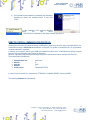
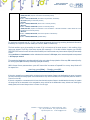
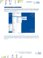
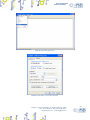
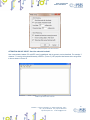
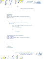
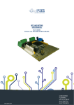
AXES CONTRO UNIT MT2HC USER MANUAL Rel. 01.01.0002 (Hardware code: MT2HC) 1 www.ipses.com AXES CONTRO UNIT MT2HC USER MANUAL _____________________________ Information provided in this manual is property of IPSES S.r.l. and must be considered and treated as confidential. This publication can only be reproduced, transmitted, transcribed or translated into any human or computer language with the written consent of IPSES S.r.l. Information in this documentation has been carefully checked and is believed to be accurate as of the date of publication; however, no responsibility is assumed of inaccuracies. IPSES will not be liable for any consequential or incidental damages arising from reliance on the accuracy of this documentation. Information contained in this manual is subject to change without notice and does not represent a commitment on the part of IPSES. The design of this instrument is subject to continue development and improvement. Consequently, the equipment associated to this document may incorporate minor changes in detail from the information hereafter provided. All brand or product names are trademarks or registered trademarks of their respective holders. This manual in English is the original version. Printed in Italy Copyright 2009-2015IPSES S.r.l. All rights reserved. 2 IPSES S.r.l. Via Suor Lazzarotto, 10 - 20020 Cesate (MI) - ITALY Tel. (+39) 02 39449519 Fax (+39) 02 700403170 http://www.ipses.com e-mail [email protected] AXES CONTRO UNIT MT2HC USER MANUAL GUARANTEE IPSES warrants to the end-user in accordance with the following provisions that its branded hardware products, purchased by the end-user from IPSES company or an authorized IPSES distributor will be free from defects in materials, workmanship and design affecting normal use, for a period of one year as of the original purchase date. Products for which proper claims are made will, at IPSES’s option, be repaired or replaced at IPSES’s expense1. Exclusions This Guarantee does not apply to defects resulting from: improper or inadequate installation, use or maintenance; actions or modifications by unauthorized third parties or the end-user; accidental or wilful damage or normal wear and tear. Making a claim Claims must be made by contacting IPSES office within the guarantee period. Please, contact: IPSES S.r.l. - Via Suor Lazzarotto, 10 - 20020 Cesate (MI) Italy Tel. (+39) 02 39449519 – (+39) 02 320629547 Fax (+39) 02 700403170 http://www.ipses.com - e-mail: [email protected] Limitation and Statutory Rights IPSES makes no other warranty, guarantee or like statement other than as explicitly stated above and this Guarantee is given in place of all other guarantees whatsoever, to the fullest extent permitted by law. In the absence of applicable legislation, this Guarantee will be the end-user’s sole and exclusive remedy against IPSES. General Provisions IPSES makes no express warranties or conditions beyond those stated in this warranty statement. IPSES disclaims all other warranties and conditions, express or implied, including without limitation implied warranties and conditions of merchantability and fitness for a particular purpose. IPSES’s responsibility for malfunctions and defects in hardware is limited to repair and replacement as set forth in this warranty statement. IPSES does not accept liability beyond the remedies set forth in this warranty statement or liability for incidental or consequential damages, including without limitation any liability for products not being available for use or for lost data or software. 1 With the exclusion of shipping costs for and from IPSES’s development office. 3 IPSES S.r.l. Via Suor Lazzarotto, 10 - 20020 Cesate (MI) - ITALY Tel. (+39) 02 39449519 Fax (+39) 02 700403170 http://www.ipses.com e-mail [email protected] AXES CONTRO UNIT MT2HC USER MANUAL WARNING! ELECTRICAL DEVICES COULD DAMAGE EQUIPMENT OR PROPERTY OR CAUSE PERSONAL INJURY This guide contains instructions and technical features of the AXES CONTRO UNIT MT2HC. Read with attention before attempting to install. It is the responsibility of the technician to undertake all the safety rules provided by the law during the installation and the use of this device. For any information which is not contained in this guide, please contact: IPSES S.r.l. - Via Suor Lazzarotto, 10 - 20020 Cesate (MI) Italy Tel. (+39) 02 39449519 – (+39) 02 320629547 Fax (+39) 02 700403170 http://www.ipses.com - e-mail: [email protected] 4 IPSES S.r.l. Via Suor Lazzarotto, 10 - 20020 Cesate (MI) - ITALY Tel. (+39) 02 39449519 Fax (+39) 02 700403170 http://www.ipses.com e-mail [email protected] AXES CONTRO UNIT MT2HC USER MANUAL TABLE OF CONTENTS REVISION HISTORY .......................................................................................................................................................... 6 GENERAL FEATURES ....................................................................................................................................................... 7 BOARD DESCRIPTION ...................................................................................................................................................... 8 BOX DESCRIPTION ......................................................................................................................................................... 10 BOX CONNECTIONS ....................................................................................................................................................... 12 DRIVER INSTALLATION ................................................................................................................................................. 14 REMOTE CONTROL COMMUNICATION PROTOCOL ................................................................................................... 17 AUXILIARY OUTPUTS ..................................................................................................................................................... 24 AUXILIARY INPUTS ......................................................................................................................................................... 26 MOTOR CONNECTION .................................................................................................................................................... 27 MOTOR CONNECTION (8 LEAD MOTORS) ................................................................................................................... 27 MOTOR CONNECTION (6 LEAD MOTORS) ................................................................................................................... 28 MOTOR CONNECTION (4 LEAD MOTORS) ................................................................................................................... 30 TECHNICAL FEATURES .................................................................................................................................................. 31 CONNECTION EXAMPLE: HYPERTERMINAL ................................................................................................................ 32 EXAMPLE USING THE DLL D2XX ................................................................................................................................... 37 PRODUCT CODES........................................................................................................................................................... 40 OTHER AVAILABLE MODELS ......................................................................................................................................... 41 CONTACTS ...................................................................................................................................................................... 42 SUPPORT INFORMATION ............................................................................................................................................... 43 PROBLEM REPORT......................................................................................................................................................... 43 ENGINEERING PROBLEM REPORT............................................................................................................................... 44 5 IPSES S.r.l. Via Suor Lazzarotto, 10 - 20020 Cesate (MI) - ITALY Tel. (+39) 02 39449519 Fax (+39) 02 700403170 http://www.ipses.com e-mail [email protected] AXES CONTRO UNIT MT2HC USER MANUAL REVISION HISTORY Manual revision history Revision/ Date 01.00.0000 November, 2010 01.01.0000 January, 2011 01.01.0001 March, 2011 01.01.0002 June, 2015 Change description Author First version Released Mancuso C. Added board description and commands “C?”, Zancanato A. “CDx” Update Hyper Terminal picture Zancanato A. Update document layout Bottaccioli M. 6 IPSES S.r.l. Via Suor Lazzarotto, 10 - 20020 Cesate (MI) - ITALY Tel. (+39) 02 39449519 Fax (+39) 02 700403170 http://www.ipses.com e-mail [email protected] AXES CONTRO UNIT MT2HC USER MANUAL GENERAL FEATURES The system MT2HC is a control axes unit which can control both two bipolar or two unipolar stepper motors (i.e. 8 and 4 lead motors, and 6 lead centred tapped motors). The system is equipped with four digital optocoupled inputs and two digital optocoupled outputs which can be used to manage by software the limit/home detection sensors and/or to interface the unit to a PLC or to other logical devices. The motor control and the device configuration are achieved through a USB interface, easily managed by the provided driver (WHQL certified). The driver allows user to communicate with the system in two ways: or by a virtual COM port or by a specific DLL. See the relevant chapters for further information about. The motor rotation speed can be easily and independently configured in steps to answer user needs. Moreover, MT2HC device is equipped with a PWM current control system on the motor phases so to keep the excitation current at the value that best meet your needs (1A, 2A or 3A). The system MT2HC is available in MT2HC version (only board), or MT2HC-BOX version that include box and internal power supply. 7 IPSES S.r.l. Via Suor Lazzarotto, 10 - 20020 Cesate (MI) - ITALY Tel. (+39) 02 39449519 Fax (+39) 02 700403170 http://www.ipses.com e-mail [email protected] AXES CONTRO UNIT MT2HC USER MANUAL BOARD DESCRIPTION In this section there is a description of the board showing: configuration jumpers, status LEDs and connectors of the MT2HC board. In Picture 1 the position of the items listed above is shown. DIPWR P3 P2 DOPWR P1 D21, D22 M2B D17, D18, D19, D20 M2A D2 M1B USB connector M1A MTPWR J5, J6 D7 Picture 1: MT2HC – Position of connectors, LEDs and Jumpers The board has two connectors blocks: one is for motor connection (composed by M1A, M1B, M2A, M2B, MTPWR) and the other one is dedicated to digital I/O connection (composed by P1, P2, P3, DIPWR, DOPWR). Motor connections block The motor power supply, which must be inlcuded between 18V and 30V, is supplied through the MTPWR connector, while the Mnm connectors allowed the connection toward the motors phases: n identifies the number of the motor (1 for motor one and 2 for motor two) and m identifies the motor phase (A or B); for example connector M1B indicates motor 1 and phase B. For further information about motor connections, see the “MOTOR CONNECTION” section. Digital I/O block The input reference voltage and a possible inputs pull-up are both available thanks to DIPWR connector, while DOPWR connector make available output voltage reference and outputs pull-up. 8 IPSES S.r.l. Via Suor Lazzarotto, 10 - 20020 Cesate (MI) - ITALY Tel. (+39) 02 39449519 Fax (+39) 02 700403170 http://www.ipses.com e-mail [email protected] AXES CONTRO UNIT MT2HC USER MANUAL The four digital inputs are available on P1 and P2, while the two open collector digital outputs are available on P3 connector. The input status is showed by LEDs D17, D18, D19, D20, while the output status is showed by LEDs D20, D21. For further information about digital I/O see “AUXILIARY OUTPUTS” and ”AUXILIARY INPUTS” sections. Jumpers description: - J5 and J6:these jumpers allow to set excitation current for motors and threshold current value for fault condition. Through “C?” command you can know via software the jumper configuration. J5 and J6 configuration: Insert J5 – Open J6 - Excitation current at3A - Current value for fault condition at 3.3A Open J5 – Open J6 - Excitation current at 2A - Current value for fault condition at 2.3A Open J5 – Insert J6 - Excitation current at 1A - Current value for fault condition at 1.4A Insert J5 – Insert J6 – Reserved LEDs description: - D17, D18, D19, D20 show the input status. - D21, D22 show the output status. - D7 green: USB connection is activated. - D2 red: motor current gone over the threshold value which has been selected by jumpers J5 and J6 (fault error). In case of fault error the motor that has caused it is immediately stopped and LED D2 turns on; if a status request is send (“U?” command), D2 turns off. 9 IPSES S.r.l. Via Suor Lazzarotto, 10 - 20020 Cesate (MI) - ITALY Tel. (+39) 02 39449519 Fax (+39) 02 700403170 http://www.ipses.com e-mail [email protected] AXES CONTRO UNIT MT2HC USER MANUAL BOX DESCRIPTION In Picture 2a the front of MT2HC-BOX is shown: connectors for motors and USB port are underlined. Connector for Motor 1 Led showing USB connection status Connector for Motor 2 Power Switch USB Port Picture 2a: MT2HC-BOX – Position of connectors and USB Port In Picture 2b the rear of MT2HC BOX is shown: socket the socket to link the box to the electrical network (100~250VAC or 140~350VDC) and fuse are underlined. The fuse is for protection of the 15VDC outputs which are on the two frontal motor connectors. 10 IPSES S.r.l. Via Suor Lazzarotto, 10 - 20020 Cesate (MI) - ITALY Tel. (+39) 02 39449519 Fax (+39) 02 700403170 http://www.ipses.com e-mail [email protected] AXES CONTRO UNIT MT2HC USER MANUAL Socket to link the box to electrical network Fuse Picture 2b: MT2HC-BOX – rear of the box Also inside the socket to link the box to electrical network there is a fuse on the power supply input for general protection. Breadth, height and length of the box are respectively 203 mm, 133 mm and 279 mm (8.0 x 5.2 x 11.0 inches). 11 IPSES S.r.l. Via Suor Lazzarotto, 10 - 20020 Cesate (MI) - ITALY Tel. (+39) 02 39449519 Fax (+39) 02 700403170 http://www.ipses.com e-mail [email protected] AXES CONTRO UNIT MT2HC USER MANUAL BOX CONNECTIONS On the front panel (see picture 2a in the previous chapter) there are two standard DB25 female connectors to connect motors. Each connector has 25 pins, the pinout is the following one: pin13 pin1 pin25 pin14 DB25 connector pin Motor pin 1 Pull-up inputs 2 AUX IN REF. Reference for open collector inputs 3 AUX IN 1 4 AUX IN 2 5 AUX IN 3 6 AUX IN 4 7 GND 8 +15V (protected by a 1A fuse) 9 N.C. 10 N.C. 11 N.C. 12 N.C. 13 Pull-up for the outputs 14 AUX OUT REF: reference for voltage open collector outputs 15 AUX OUT 1: open-collector toward pin14. 16 AUX OUT 2: open-collector toward pin14. 17 N.C. 18 N.C. 19 N.C. 20 N.C. 21 N.C. 22 Motor Phase B+ 12 IPSES S.r.l. Via Suor Lazzarotto, 10 - 20020 Cesate (MI) - ITALY Tel. (+39) 02 39449519 Fax (+39) 02 700403170 http://www.ipses.com e-mail [email protected] AXES CONTRO UNIT MT2HC USER MANUAL 23 Motor Phase B- 24 Motor Phase A+ 25 Motor Phase A- We suggest to connect the USB cable between the system and the PC only after the power on of the device. All connections, with the exclusion of the four phases of the motor (pin 22÷25) are shared between the two connector. For instance the output “AUX OUT 1” is present on pin 15 of the connector of the first motor and on pin 15 of the connector of the second motor. ATTENZIONE! Do not connect or disconnect motors (or any of their phases) when the system is power supplied (even though the motor is stop)! 13 IPSES S.r.l. Via Suor Lazzarotto, 10 - 20020 Cesate (MI) - ITALY Tel. (+39) 02 39449519 Fax (+39) 02 700403170 http://www.ipses.com e-mail [email protected] AXES CONTRO UNIT MT2HC USER MANUAL DRIVER INSTALLATION We recommend to execute the automatic software installation from CD before connecting the device to PC. By this way, software and USB driver are both installed, allowing the PC to automatically identify the device once you connect it. If you use the recommend automatic software installation from CD, you do not need to follow indications contained in this chapter. If you do not use the recommend automatic software installation from CD, to connect MT2HC-Box to your PC you need to install only the USB IPSES driver that is certified for the most recent Microsoft operating systems: - Microsoft Windows 2000 family - Microsoft Windows XP family, x86 - Microsoft Windows Server 2003 family, x86 - Microsoft Windows Server 2003 family, x64 - Microsoft Windows XP family, x64 - Microsoft Windows Vista family, x86 - Microsoft Windows Vista family, x64 - Windows Server 2008 family, x86 - Windows Server 2008 family, x64 –Windows 7 - Windows 7 x64 - Windows Server 2008 Release 2 family, x64 If your PC has an internet connection, you should follow the automatic Windows Update procedure, otherwise follow the manual installation procedure from CD. 14 IPSES S.r.l. Via Suor Lazzarotto, 10 - 20020 Cesate (MI) - ITALY Tel. (+39) 02 39449519 Fax (+39) 02 700403170 http://www.ipses.com e-mail [email protected] AXES CONTRO UNIT MT2HC USER MANUAL Automatic Windows Update procedure 1) Connect the MT2HC to PC using a USB cable. Windows operating system will detect a new device, showing a message similar to: 2) In the following windows “found new hardware wizard” chose “Yes, this time only” and then “Next”. Wait for a complete download of the driver and its installation. 3) 4) Installation displayed. is Then choose “install the software automatically (Recommended)” and then “Next”. Wait for downloading of the driver and its installation. completed when the window on the left is Choose “Finish” to exit. 5) After a window with the message “Found New Hardware. USB Serial Port” is displayed. Follow again instruction from point 2) 15 IPSES S.r.l. Via Suor Lazzarotto, 10 - 20020 Cesate (MI) - ITALY Tel. (+39) 02 39449519 Fax (+39) 02 700403170 http://www.ipses.com e-mail [email protected] AXES CONTRO UNIT MT2HC USER MANUAL Manual driver installation procedure 1) Connect the MT2HC board to PC using a USB cable. Windows operating system will detect a new device, showing a message similar to: 2) In the following windows “found new hardware wizard” chose “No, not this time” and then “Next”. 3) Then choose “install from a list or specific location (Advanced)” and “Next”. Then Set the driver folder path on the CD. 16 IPSES S.r.l. Via Suor Lazzarotto, 10 - 20020 Cesate (MI) - ITALY Tel. (+39) 02 39449519 Fax (+39) 02 700403170 http://www.ipses.com e-mail [email protected] AXES CONTRO UNIT MT2HC USER MANUAL 4) The Successful of the installation is indicated by the message of completing the found new hardware wizard. To end, click "Finish". 5) After installation of the hardware described above, the new device "USB Serial Port" is detected. Follow again instruction from point 2). REMOTE CONTROL COMMUNICATION PROTOCOL Communication of control unit is achieved through a USB interface, made up by the driver, which is provided with the unit. Commands are strings in ASCII code terminated with <CR>(0x0D). The syntax is case-sensitive so it is not possible to use either lowercase or uppercase. In case the user chooses to use the virtual COM port available through the driver, commands can be directly conveyed with any serial client (Windows HyperTerminal, for example). Moreover, application programs may be developed using USB communication functions provided with D2XX DLL. The communication parameter are: Communication rate: data bits: parity bit: stop bits: stream control: 9600 baud 8 none 1 Hardware(CTS/RTS) In case of choice to use the DLL, please refer to “FTD2XX.DLL DYNAMIC LIBRARY” manual by IPSES. The following commands are implemented: 17 IPSES S.r.l. Via Suor Lazzarotto, 10 - 20020 Cesate (MI) - ITALY Tel. (+39) 02 39449519 Fax (+39) 02 700403170 http://www.ipses.com e-mail [email protected] AXES CONTRO UNIT MT2HC USER MANUAL Sx,y Sets the steady speed of the motor in step per second: where x is the speed for motor 1, y is the speed for motor 2. Note: the speed must be set between the starting speed (defined by the Sm command) and 99999 step/s. i.e. S1000,500 sets at 1000 step/s the steady speed of the motor 1 and at 500 step/s the one of motor 2. S? Requests the set steady speeds (in step per second) for the two motors. The answer will be in the following format: +XXXXX,+YYYYY<CR>, where XXXXX is the set steady speed for the motor 1, while YYYYY is the one for the motor 2. i.e. after sending S?, the system will answer with +01000,00500 that means the speed for motor 1 is 1000 step/s while speed of motor 2 is 500 step/s. Smx,y Sets the starting speed of motors in steps per second: x is the speed for motor 1, while y is the speed for motor 2. Speed must be include between 5 and the steady speed which is set by the S command (it cannot be more than 99999 step/s). i.e. Sm20,50 sets at 20 step/s the starting speed of motor 1 and at 50 step/s the starting speed of motor 2. Sm? Requests the starting speed in step per second that has be set for the two motors. The system answers in the following format: +XXXXX,+YYYYY<CR>, where XXXXX is the set starting speed for motor 1 while YYYYY is the one of motor 2. i.e. after sending Sm?, the system will answer with +00020,+00050 that means the starting speed for motor 1 is 20 step/s while the one for motor 2 is 50 step/s. SXx Sets the steady speed of the motor 1 in step per second where x represents the speed for the motor 1. Note: the speed must be set between the starting speed (defined by the Sm command) and 99999 step/s. i.e. SX1000 sets at 1000 step/s the steady speed of motor 1 while the speed of motor 2 is unchanged. SYy Sets the steady speed of the motor 2 in step per second where y represents the speed for the motor 2. Note: the speed must be set between the starting speed (defined by the Sm command) and 99999 step/s. i.e. SY500 sets at 500 step/s the steady speed of motor 2 while the speed of motor 1 is unchanged. RSx,y Defines the number of steps used for the acceleration/deceleration ramp for the motor 1 and 2 respectively. Note the number of steps must be positive and less than 99999 (or zero to disable the ramp). i.e. RS100,0 sets at 100 steps the number of steps requiered to reach the steady speed from the starting speed of motor 1 and disabile the ramp for motor 2. RS? Requests the number of set steps which are usend for the acceleration/deceleration ramp for motor 1 and 2 respectively. The system will answer with the following format: +XXXXX,+YYYYY<CR>, where XXXXX is the set value for motor 1, while YYYYY is the value for motor 2. i.e. after the sending of RS?, the answer will be +00100,+00001 which means for motor one the number of steps for reach the steady speed form the starting sped (so the set step in the acceleration ramp) is 100 while the acceleration ramp for motor 2 is disabled. 18 IPSES S.r.l. Via Suor Lazzarotto, 10 - 20020 Cesate (MI) - ITALY Tel. (+39) 02 39449519 Fax (+39) 02 700403170 http://www.ipses.com e-mail [email protected] AXES CONTRO UNIT MT2HC USER MANUAL Gx,y Enables or disable the perpetual motion for the two motors: x is the parameter for motor 1, y is the parameter for motor 2. x,y parameters can have the following values: 1 which set the perpetual motion in positive direction, -1 which set the perpetual motion in negative direction and 0 to stop the perpetual motion. i.e. G1,-1 sets the perpetual motion in positive direction for motor 1 and in negative direction for motor 2. GXx Enables or disable the perpetual motion for the motor 1: x is the parameter for motor 1 which can have the following values: 1 which set the perpetual motion in positive direction, -1 which set the perpetual motion in negative direction and 0 to stop the perpetual motion. i.e. GX1, sets the perpetual motion in positive direction for the motor 1. The status of perpetual motion for motor 2 is kept unchanged. GYy Enables or disable the perpetual motion for the motor 2: x is the parameter for motor 2 which can have the following values: 1 which set the perpetual motion in positive direction, -1 which set the perpetual motion in negative direction and 0 to stop the perpetual motion. i.e. GY-1, sets the perpetual motion in negative direction for the motor 2. The status of perpetual motion for motor 1 is kept unchanged. G. Stops immediately (with no deceleration ramp) both motors when they are running G? Requests the set value for perpetual motion for the two motors. The answer will be in the following format: a0000X,b0000Y<CR> where a and b indicate the direction of the set perpetual motion for the two motors (+ for positive direction, - for negative direction), while X and Y are 1 is the perpetual motion is enabled or 0 is it is disabled i.e. after the sending of G?, the answer will be +00001,-00001 which indicates the perpetual motion is enabled for motor 1 in positive direction and is enabled in negative direction for motor 2. Hx,y Set the current position as home position for the two motors: x is the parameter for motor1, while y is the one for motor 2. The x,y parameters can have the following values: 1 sets the current position as home position, 0 keeps unchanged the home position. i.e. after the sending of H0,1, the system does not modify the home position for motor 1, while it sets the current position as home position for motor 2. Px,y Moves the axes to the coordinate position (x,y), where x and y are the absolute positions from home position in steps. Both x and y must be include between -99.999 and +99.999. i.e. after the sending of P-200,1000, the system drives motor 1 in a position of 200 steps in negative direction and motor 2 in a position of 1000 steps in positive direction from the home position previously set through H command. The use of this command implies position is known. 19 IPSES S.r.l. Via Suor Lazzarotto, 10 - 20020 Cesate (MI) - ITALY Tel. (+39) 02 39449519 Fax (+39) 02 700403170 http://www.ipses.com e-mail [email protected] AXES CONTRO UNIT MT2HC USER MANUAL PXx Moves the motor 1 to the position of x coordinate, where x is the absolute position from home position in step. x must be include between -99.999 and +99.999. i.e. after the sending of PX-200 the system drives motor 1 in a position of 200 steps in negative direction from the home position previously set through H command. Status of motor 2 is kept unchanged. The use of this command implies position is known. PYy Moves the motor 2 to the position of y coordinate, where y is the absolute position from home position in step. x must be include between -99.999 and +99.999. i.e. after the sending of PY1000 the system drives motor 2 in a position of 1000 steps in positive direction from the home position previously set through H command. Status of motor 1 is kept unchanged. The use of this command implies position is known. W? Requests the current position. The system will answer with the following aXXXXX,bYYYYY<CR> where a and b indicate the direction positive or negative and XXXXX and YYYYY indicate the movement from home position in steps. i.e. after the sending of W?, the answer will be -00200,+01000 that means motor 1 is at 200 steps in negative direction from home position previously set by H command and motor 2 is at 1000 steps in positive. The use of this command implies position is known. Dx,y Moves the axes for a run of x and y steps from current position (relative movement) x and y are the runs in steps (both must be included between -99.999 and +99.999). i.e. after the sending of D-200,1000, the system drives motor 1 in a position of 200 steps in negative direction from current position and motor 2 in a position of 1000 steps in positive direction from current position. Fx,y Allows the phases of the two motors to remain activated when they are in stop mode: x is the parameter for motor 1, y is the one for motor 2. The x,y parameters can have the following values: 1 phases enabled when motor in stop mode, 0 phases disabled when motor is in stop mode. When pahses are enabled, the current is about 1A per pahse so to reduce consumptions and prevents the possibility of overheating. i.e. F1,0 when motor 1 will be in stop mode, in its phases there will be current, while when motor 2 will be in stop mode its phases will be disabled. F? Requests the set value for the motor phases when the motors are in stop mode. The answer will be in the following format +0000X,+0000Y<CR> where X and Y are 1 if the phases are enabled and 0 if they are disabled. i.e. after the sending of F?, the answer will be +00001,+00000 that means when motor 1 will be in stop mode, in its phases there will be current, while when motor 2 will be in stop mode its phases will be disabled. C? Requests the set value for the excitation current. The answer will be in the following format X<CR> where X can be 1, 2 or 3 depending on J5 and J6 configuration (see “BOARD DESCRIPTION” section). i.e. after the sending of C?, the answer will be 2 that means the excitation current is 2A and threshold current is 2.3A (J5 and J6 are open). 20 IPSES S.r.l. Via Suor Lazzarotto, 10 - 20020 Cesate (MI) - ITALY Tel. (+39) 02 39449519 Fax (+39) 02 700403170 http://www.ipses.com e-mail [email protected] AXES CONTRO UNIT MT2HC USER MANUAL Requests data about current flowing in the x motor phases, where x is 1 for the first motor or 2 for the second one. The answer will be an array with maximum length of 401 bytes where: the first byte is the number of the sample for each phase (unsigned 8 bit number), followed by the samples of A phase (signed 8 bit number) and then by the samples of B phase (signed 8 bit number). The samples have to be multiplied by 0,1101764 to obtain current in ampere. i.e. after the sending of CD1 the answer will be an array of 401 bytes: 200(xC8), 25(x19), 27(x1B), …, 0(x00), …, -25(xE7), -25(xEC)… The first byte indicate that 200 samples for each phase of the first motor are available, the other 200 bytes are the phase A samples and the last 200 bytse are the samples of phase B. For obtain the current value, multiply the sample by 0,1101764: CDx 25(x19)*0,1101764=2,75A; 27(x1B)*0,1101764=2,97A; …; 0(x00)*0,1101764=0A; …; -25(xE7)*0,1101764=-2,75A; -20(xEC)*0,1101764=2.2A; … i.e: after the sending of CD2, the answer will be an array of 301 bytes: 150(x96), 25(x19), 27(x1B), …, 0(x00), …, -25(xE7), -25(xEC)… In this case the number of samples for each phase of the motor 2 are 150, formatted the same way as the previous example. On1,n2 Sets the value of the digital outputs: 1 output enabled, 0 output disabled ( n1 and n2 are referred to the two outputs respectively). i.e. O1,0 output 1 is enabled and output 2 is disabled. O? Requests the status of the outputs and the system will answer in the following format: +0000X,+0000Y<CR> where X and Y values are 1 if the relevant output is enabled, 0 if it is disabled. i.e. after the sending of O?, the answer will be +00001,+00000 that means the output 1 is enabled and the output 2 is disabled. IO? Requests the status of inputs and outputs and the system will answer in the following format: +0XYZT,+000AB <CR>, where X, Y, Z, T value is 1 is the pertinent input is enable, otherwise is 0 and A, B value is 1 is the pertinent output is enable, otherwise is 0. i.e. after the sending of IO?, the answer will be +01101,+00010 that means inputs 1,2 and 4 and output 1 are enabled, while input 3 and output 2 are disabled. ? Requests the current firmware version and the serial number of the device The answer will be an ASCII string similar to “MT2HC vX.XX.XXXX SN:YYYYYYY by IPSES srl (www.ipses.com)\r”, where X.XX.XXXX is the firmware version and YYYYYYY is the serial number. M Saves the currently used speed and working mode settinngs in a non-volatiole memory. MR 21 IPSES S.r.l. Via Suor Lazzarotto, 10 - 20020 Cesate (MI) - ITALY Tel. (+39) 02 39449519 Fax (+39) 02 700403170 http://www.ipses.com e-mail [email protected] AXES CONTRO UNIT MT2HC USER MANUAL Reset in a non-volatile memory the factory configuration parameters. U? Requests the system status. The answer will be in the following format: +FCLAX,+000BY<CR>, where F is 1 if a fault status occurred; C is 1 if an invalid command has been sent; L is 1 if you have exceeded the limits of the parameters; A,B are 1 if the position of the relevant motor is unknown; X, Y are 1 if the relevant motor is running. F, C, L are reset after the U command while A, B are reset when an home position is set through H command, then X, Y are reset if motors are in stop mode. Example1(fault): ->U?<CR> Answer->+00010,+00010<CR> ->G0,1<CR> (perpetual motion on motor 2 in positive direction) ->U?<CR> Answer->+00010,+00011<CR> (motor 2 is running). FAULT ERROR ->U?<CR> Answer->+10010,+00010<CR> (fault error. Motor 2 is stopped). Example2 (not provided command): ->U?<CR> Answer ->+00010,+00010<CR> ->NOEXIST<CR> (sending a not provided string) ->U?<CR> Answer ->+01010,+00011<CR> (not provided command):). Example3(exceeding of parameter limits): ->U?<CR> Answer ->+00010,+00010<CR> ->Sm50,100<CR> (Setting the minimum speed) ->S50,50<CR> (Setting the steady speed) ->U?<CR> Answer ->+00110,+00010<CR> (The steady speed of the second motor is lowen than its minimum speed). Example4(motors in running condition): ->U?<CR> Answer ->+00010,+00010<CR> ->G0,1<CR> (perpetual motion on motor 2 in positive direction) ->U?<CR> Answer ->+00010,+00011<CR> (motor 2 is running). ->GX-1<CR> (perpetual motion on motor 1 in negative direction) ->G?<CR> Answer ->-00001,+00001<CR> (perpetual motion of the two motors in two different directions). ->U?<CR> Answer ->+00011,+00011<CR> (both motors are running with unspecified directions. These flags are enabled at every movement, so also with D, P, PX, PY commands). Example 5(Unknown position): ->U?<CR> Answer ->+00010,+00010<CR> (motors are in unknown positions) ->W?<CR> 22 IPSES S.r.l. Via Suor Lazzarotto, 10 - 20020 Cesate (MI) - ITALY Tel. (+39) 02 39449519 Fax (+39) 02 700403170 http://www.ipses.com e-mail [email protected] AXES CONTRO UNIT MT2HC USER MANUAL Answer ->+99999,+99999<CR> (the answer in case of unknown position) ->P9000,100<CR> (request of movement to absolute position) ->U?<CR> Answer ->+00110,+00010<CR> (movement not performed, invalid limit) ->H1,1<CR> (setting a new home position) ->U?<CR> Answer ->+00000,+00000<CR> (motors are in a known position). ->W?<CR> Answer ->+00000,+ 00000<CR> (motors are at home position) ->P9000,100<CR> (request of movement to set coordinates – absolute movement - these values are to be considered from set home position) ->W?<CR> Answer ->+09000,+00100<CR> (new current position of the motors). ->U?<CR> Answer ->+00000,+00000<CR> (system status). For each query command sent (W ', O',? Etc..) the device will respond with the string containing the desired information, followed by the inspection character <CR> (13 in decimal, 0x0D in hexadecimal). The fault condition occurs by exceeding the current of 3A in at least one of the motor phases, in this condition all the motors are stopped. The F flag of the status request (U? command) is 1 if the fault condition happens (see “BOARD DESCRIPTION” section for more info about fault condition) and it will be reset every time a status request (U? command) is sent. All the positions and movements must be understood as measured in full steps, as the measured speeds are expressed in full steps per second. The acceleration/deceleration ramp depends both by the set number of steps (duration of the ramp, RS command) and by the starting speed (Sm command) and steady speed (S command). With these three parameters you will have the increase of speed for every step that will be equal to: ___starting speed(Sm) – Steady speed(S)___ Duration of ramp (RS) If there is a request for a movement which is higher than the total number of steps to be dedicated to the ramp, the system will reach and keep the steady speed until the deceleration ramp will be activated, with a trapezoidal pattern as shown in Picture 3 on the left. If there is a request for a movement which is lower than the total number of steps to be dedicated to the ramp, the system will assign half of the movement to the acceleration ramp, and half to the deceleration ramp, without ever reaching the steady speed, with a trend always shown in Picture 3 on the right. 23 IPSES S.r.l. Via Suor Lazzarotto, 10 - 20020 Cesate (MI) - ITALY Tel. (+39) 02 39449519 Fax (+39) 02 700403170 http://www.ipses.com e-mail [email protected] AXES CONTRO UNIT MT2HC USER MANUAL Picture 3: on the left the speed trend with a movement higher than the number of steps requested by the ramp is shown, on the right the pattern with a movement lower than the number of steps of the ramp is shown. In case of a request for changing the motion direction, before reversing the motion, the system will apply the deceleration ramp up to reach the starting speed and then it will reverse the motion by applying the acceleration ramp (see Picture 4). Picture 4: Trend of the speed in case of requesting motion inversion Factory parameter values, which can be restored using the MR command, are: - starting speed: 25 steps per second for both motors (Sm), - steady speed: 200 steps per second for both motors (S), - ramp duration: 250 steps for both motors (RS), - Phases disabile when motors are in stop mode (F) AUXILIARY OUTPUTS On the device there are two optocuopled outputs which can be managed using the O command. Their status can be verified using O? (alternatively you can also use the IO? command). The outputs are open collectors which can be connected to a pull-up. Features of the outputs are the following ones: Maximum output voltage: 36V Maximum output current: 150 mA 24 IPSES S.r.l. Via Suor Lazzarotto, 10 - 20020 Cesate (MI) - ITALY Tel. (+39) 02 39449519 Fax (+39) 02 700403170 http://www.ipses.com e-mail [email protected] AXES CONTRO UNIT MT2HC USER MANUAL Here below there are the diagrams of two typical connection of external devices toward the MT2HC system. In the first case (Picture 5a) the system directly controls some loads (with maximum current of 150mA). In the second case (Picture 5b) the systems is interfaced to a high impedance device (for instance the inputs of a PLC). DOPWR (pin14) (pin15) P3 (pin16) Picture 5a: Connection of auxiliary outputs: directly managing of loads. The correspondent pins of the DB25 connectors in BOX version are indicated in parenthesis. (pin14) DOPWR (pin13) (pin15) P3 (pin16) Picture 5b: Connection of auxiliary outputs: connection to a high impedance device. The correspondent pins of the DB25 connectors in BOX version are indicated in parenthesis. 25 IPSES S.r.l. Via Suor Lazzarotto, 10 - 20020 Cesate (MI) - ITALY Tel. (+39) 02 39449519 Fax (+39) 02 700403170 http://www.ipses.com e-mail [email protected] AXES CONTRO UNIT MT2HC USER MANUAL AUXILIARY INPUTS The system is equipped with four optocoupled inputs. It is possible to verify their status using IO? command. To use these inputs, it is necessary to polarize the optocouplers (see the two diagrams below). Input features are the following ones: Maximum applicable voltage: 36V LOW logic level: <1V HIGH logic level: >2.5V Input impedance: 2.5 Kohm We suggest to connects the inputs according one of the two diagrams shown below: - Picture 6a: in the case the inputs are controlled directly by a voltage. - Picture 6b: in the case the inputs must detect the pressure of a button or an open collector output. DIPWR (pin2) (pin6) P2 (pin5) (pin4) P1 (pin3) Picture 6a: Connection of the inputs: directly voltage control. The correspondent pins of the DB25 connectors in BOX version are indicated in parenthesis. 26 IPSES S.r.l. Via Suor Lazzarotto, 10 - 20020 Cesate (MI) - ITALY Tel. (+39) 02 39449519 Fax (+39) 02 700403170 http://www.ipses.com e-mail [email protected] AXES CONTRO UNIT MT2HC USER MANUAL (pin1) DIPWR (pin2) (pin6) P2 (pin5) (pin4) P1 (pin3) Picture 6b: Connection of the inputs: detection of the pressure from a switch or an open collector output. The correspondent pins of the DB25 connectors in BOX version are indicated in parenthesis. MOTOR CONNECTION MT2HC can control both two bipolar and two unipolar stepper motors, i.e. 8, 4 and 6 lead centre tapped motors. Here the possible different motor connections are showed. MOTOR CONNECTION (8 LEAD MOTORS) Series connection A series motor configuration would typically be used in application where a higher torque at lower speeds is required. Because this configuration has the most inductance, the performance will start to degrade at higher speeds. Phase A+ Phase APhase B+ Phase B- Picture 7: series connection. 27 IPSES S.r.l. Via Suor Lazzarotto, 10 - 20020 Cesate (MI) - ITALY Tel. (+39) 02 39449519 Fax (+39) 02 700403170 http://www.ipses.com e-mail [email protected] AXES CONTRO UNIT MT2HC USER MANUAL Parallel connection An 8 lead motor in a parallel configuration offers a more stable, but lower torque at lower speeds. But because of the lower inductance, there will be higher torque at higher speeds. Phase A+ Phase APhase B+ Phase B- Picture 8: parallel connection. MOTOR CONNECTION (6 LEAD MOTORS) Half coil configuration This configuration uses 50% of the motor phase windings. This gives lower inductance, hence, lower torque output. Like the parallel connection of 8 lead motor, the torque output will be more stable at higher speeds. This configuration is also referred to as half copper. Phase A+ Phase ANot connected Phase B+ Phase BNot connected Picture 9: half coil configuration. Configurazione full coil The full coil configuration on a 6 lead motor should be used in applications where higher torque at lower speeds is desired. This configuration is also referred to as full copper. Phase A+ Not connected Phase AIPSES S.r.l. Via Suor Lazzarotto, 10 - 20020 Cesate (MI) - ITALY Phase B+ Tel. (+39) 02 39449519 Fax (+39) 02 700403170 http://www.ipses.com e-mail [email protected] Not connected Phase B- 28 AXES CONTRO UNIT MT2HC USER MANUAL Picture 9: full coil configuration. 29 IPSES S.r.l. Via Suor Lazzarotto, 10 - 20020 Cesate (MI) - ITALY Tel. (+39) 02 39449519 Fax (+39) 02 700403170 http://www.ipses.com e-mail [email protected] AXES CONTRO UNIT MT2HC USER MANUAL MOTOR CONNECTION (4 LEAD MOTORS) 4 lead motors 4 lead motors are the least flexible but easiest to wire. Speed and torque will depend on winding inductance. Phase A+ Phase APhase B+ Phase B- Picture 10: 4 lead motors. NOTE The physical direction of motors depends on connection of motor windings. To switch the direction of the motor, switch the wires on either phase A or phase B outputs. 30 IPSES S.r.l. Via Suor Lazzarotto, 10 - 20020 Cesate (MI) - ITALY Tel. (+39) 02 39449519 Fax (+39) 02 700403170 http://www.ipses.com e-mail [email protected] AXES CONTRO UNIT MT2HC USER MANUAL TECHNICAL FEATURES Logic power supply: The logic is self-supplied directly from the computer USB port Motor power supply: from 18V to 30V for MT2HC version 100~250VAC or 140~350VDC for MT2HC-BOX version Motor steady current: 1A, 2A or 3A/phase, with PWM control Communication interface: USB 2.0 (connector type B) Auxiliary outputs : two outputs Maximum applicable voltage: 36V Maximum current on each open collector: 150 mA Auxiliary inputs: four inputs Maximum applicable voltage: 36V LOW logical level: <1V HIGH logical level: >2.5V Input impedance: 2.5 Kohm (about) Board 115 mm x 115 25mm (0,98 inches) dimensions: Box dimensions: mm (4.52 x 4.52 inches). Max high: 203 mm x 133 mm x 279 mm (8.0 x 5.2 x 11.0 inches). 31 IPSES S.r.l. Via Suor Lazzarotto, 10 - 20020 Cesate (MI) - ITALY Tel. (+39) 02 39449519 Fax (+39) 02 700403170 http://www.ipses.com e-mail [email protected] AXES CONTRO UNIT MT2HC USER MANUAL CONNECTION EXAMPLE: HYPERTERMINAL A typical example of serial connection is represented by HyperTerminal tool, which is present in all operating systems Microsoft Windows XP (if your PC is equipped with Windows Vista or 7, the program is not included in the operative system distributions, but it is easily downloadable from Internet), running by menu “Start -> All Programs -> Accessories -> Communications -> Hyper Terminal” (Picture 11). Picture 11: Hyper Terminal path The serial communication can be used also with USB devices because the driver provides a virtual serial communication port (VCP) for each MT2 system connected. Through the VCP it can be easily established the serial communication with the board. Once the connection is established, a name and some other parameters are needed (as it can be seen in Picture 12-13). 32 IPSES S.r.l. Via Suor Lazzarotto, 10 - 20020 Cesate (MI) - ITALY Tel. (+39) 02 39449519 Fax (+39) 02 700403170 http://www.ipses.com e-mail [email protected] AXES CONTRO UNIT MT2HC USER MANUAL Picture 12: HyperTerminal general parameter settings Picture 13: Hyper Terminal serial parameter settings Before getting information by the board it is necessary to view characters sent by user. To do that, an echo late on what is written has to be set via program properties menu (Picture 14-16). 33 IPSES S.r.l. Via Suor Lazzarotto, 10 - 20020 Cesate (MI) - ITALY Tel. (+39) 02 39449519 Fax (+39) 02 700403170 http://www.ipses.com e-mail [email protected] AXES CONTRO UNIT MT2HC USER MANUAL Picture 14: HyperTerminal properties menu Picture 15: by TAB “Settings”, user can select “ASCII Setup” 34 IPSES S.r.l. Via Suor Lazzarotto, 10 - 20020 Cesate (MI) - ITALY Tel. (+39) 02 39449519 Fax (+39) 02 700403170 http://www.ipses.com e-mail [email protected] AXES CONTRO UNIT MT2HC USER MANUAL Picture 16: an example configuration to see ASCII characters ATTENCTION: DO NOT SELECT “Send line ends with line feeds” Now communication between PC and MT2 board is established with the protocol previous described. For example, if character “?” is sent by the keyboard followed by <ENTER> (Picture 17), MT2 peripheral shall answer with a string similar to the one shown in Picture 18: Picture 17: get firmware version command 35 IPSES S.r.l. Via Suor Lazzarotto, 10 - 20020 Cesate (MI) - ITALY Tel. (+39) 02 39449519 Fax (+39) 02 700403170 http://www.ipses.com e-mail [email protected] AXES CONTRO UNIT MT2HC USER MANUAL Picture 18: firmware version string example Typing the commands one after the other, you can start working with the MT2HC system using the virtual COM port. 36 IPSES S.r.l. Via Suor Lazzarotto, 10 - 20020 Cesate (MI) - ITALY Tel. (+39) 02 39449519 Fax (+39) 02 700403170 http://www.ipses.com e-mail [email protected] AXES CONTRO UNIT MT2HC USER MANUAL EXAMPLE USING THE DLL D2XX The following code example opens the communication toward the device with 0 and configures transmission parameters, reads the firmware version and the serial number ( “?” command), sends the command for moving the X axis (2000 steps) and closes the communication. // Variables definition unsigned long ftStatus = 0, ftHandle = 0; unsigned long TxBytes = 0, RxBytes = 0, EventNode = 0, BytesWritten = 0, BytesReceived = 0; char TxBuffer [16] = “ ”; char RxBuffer [256] = “ ”; // Open Device Communication to 0 indexed device and sets its communication parameters ftStatus = FT_Open (0, &ftHandle); if (ftStatus != FT_OK) { //Error on opening procedure } else { ftStatus = FT_SetBaudRate (ftHandle, 9600); if (ftStatus != FT_OK) { //Error on setting baud rate procedure } else { ftStatus = FT_SetDataCharacteristics (ftHandle, FT_BITS_8, FT_STOP_BITS_1, FT_PARITY_NONE ); if (ftStatus != FT_OK) { //Error on setting data characteristics procedure } else { ftStatus = FT_SetFlowControl (ftHandle, FT_FLOW_RTS_CTS, NULL, NULL); if (ftStatus != FT_OK) { //Error on setting flow control procedure } else { ftStatus = FT_SetTimeouts (ftHandle, 500, 300); if (ftStatus != FT_OK) { //Error on setting timeout procedure } 37 IPSES S.r.l. Via Suor Lazzarotto, 10 - 20020 Cesate (MI) - ITALY Tel. (+39) 02 39449519 Fax (+39) 02 700403170 http://www.ipses.com e-mail [email protected] AXES CONTRO UNIT MT2HC USER MANUAL else { //Opening procedure successfully completed } } } } } //Get Info device TxBuffer = “?/r”; ftStatus = FT_Write (ftHandle, TxBuffer, sizeof(TxBuffer), &BytesWritten); if (ftStatus != FT_OK){ { //Write error } else { FT_GetStatus(ftHandle, &RxBytes, & TxBytes, &EventNode); if (RxBytes >0 ) { ftStatus = FT_Read(ftHandle, RxBuffer, RxBytes, &BytesReceived); if (ftStatus == FT_OK) { // successfully reading } else { // Error reading } } } //Send command: movement of X axis for 2000 steps TxBuffer = “D2000,0/r”; ftStatus = FT_Write (ftHandle, TxBuffer, sizeof(TxBuffer), &BytesWritten); if (ftStatus != FT_OK){ { //Write error } else { //Command sent } //Close device FT_Close (ftHandle); 38 IPSES S.r.l. Via Suor Lazzarotto, 10 - 20020 Cesate (MI) - ITALY Tel. (+39) 02 39449519 Fax (+39) 02 700403170 http://www.ipses.com e-mail [email protected] AXES CONTRO UNIT MT2HC USER MANUAL 39 IPSES S.r.l. Via Suor Lazzarotto, 10 - 20020 Cesate (MI) - ITALY Tel. (+39) 02 39449519 Fax (+39) 02 700403170 http://www.ipses.com e-mail [email protected] AXES CONTRO UNIT MT2HC USER MANUAL PRODUCT CODES Code Description MT2HC Two axes stepper motor control system with PWM current control at 3 A and USB interface. MT2HC-BOX Two axes stepper motor control system with PWM current control at 3 A and USB interface, equipped with power supply for motors. USB-A-B USB cable for USB cards and systems (lenght: 1,8m – 70.9 inches) USB-A-B-ill USB cable with light end for USB cards and systems 40 IPSES S.r.l. Via Suor Lazzarotto, 10 - 20020 Cesate (MI) - ITALY Tel. (+39) 02 39449519 Fax (+39) 02 700403170 http://www.ipses.com e-mail [email protected] AXES CONTRO UNIT MT2HC USER MANUAL OTHER AVAILABLE MODELS IPSES can realize customized versions of this device to answer to any clients’ demand. Particularly, it is possible to have this instrument in any size (so as to easily integrate it in any mechanical system) and with customized communication protocol. There are also available axes control cards and systems with USB interface (see MT2USB and MT2USBMS systems) serial interface RS232 (see the MT2 and MT2MS systems) and with Ethernet interface (see the MT2ETH and MT2ETHMS systems). On request we can conceive and develop system with any communication interface, according to our client’s specifications. For each version on demand is available the box configuration. For further information, please visit the website http://www.ipses.com. MT2USB MT2USBMS MT2 MT2MS MT2ETH MT2ETHMS 41 IPSES S.r.l. Via Suor Lazzarotto, 10 - 20020 Cesate (MI) - ITALY Tel. (+39) 02 39449519 Fax (+39) 02 700403170 http://www.ipses.com e-mail [email protected] AXES CONTRO UNIT MT2HC USER MANUAL CONTACTS IPSES S.r.l. conceives, projects and markets electronic and scientific instruments. The customized planning of our devices allows us to answer specific necessities for customers asking for embedded systems. IPSES clients enjoy access to a dedicated project engineering team, available as needed. Our pool consists of highly competent professionals whose experience in this field is extremely strong. Thanks to constant updating and technical development, IPSES is a leading company, combining the dynamism of a young group into the competence and reliability of a qualified staff. IPSES S.r.l. Research and development office: Via Suor Lazzarotto, 10 20020 Cesate (MI) Italy tel. (+39) 02 39449519 - (+39) 02 320629547 fax (+39) 02 700403170 e-mail: [email protected] http://www.ipses.com 42 IPSES S.r.l. Via Suor Lazzarotto, 10 - 20020 Cesate (MI) - ITALY Tel. (+39) 02 39449519 Fax (+39) 02 700403170 http://www.ipses.com e-mail [email protected] AXES CONTRO UNIT MT2HC USER MANUAL __________________________________ SUPPORT INFORMATION The customer is at liberty to contact the relevant engineer at IPSES S.r.l. directly. Telephone : Fax Email : : (+39) 02 39449519 (+39) 02 320629547 (+39) 02 700403170 [email protected] PROBLEM REPORT The next page is a standard template used for reporting system problems. It can be copied and send as a fax. Alternative bugs may be reported by emails, in this case please insure that the mail contains similar information listed in the Engineering Problem Report form. 43 IPSES S.r.l. Via Suor Lazzarotto, 10 - 20020 Cesate (MI) - ITALY Tel. (+39) 02 39449519 Fax (+39) 02 700403170 http://www.ipses.com e-mail [email protected] AXES CONTRO UNIT MT2HC USER MANUAL ENGINEERING PROBLEM REPORT Problem describer Name Company Date Tel. Fax IPSES s.r.l. Via Suor Lazzarotto, 10 Cesate (MI) Italy Fax (+39) 02 700403170 e-mail [email protected] Product Name Version Serial No. Report Type (bug, change request or technical problem) Major bug Minor bug Change request Technical problem Urgency: High Medium Low Problem Description Reproduction of Problem IPSES s.r.l. Action notes Received by Date Report No. Action 44 IPSES S.r.l. Via Suor Lazzarotto, 10 - 20020 Cesate (MI) - ITALY Tel. (+39) 02 39449519 Fax (+39) 02 700403170 http://www.ipses.com e-mail [email protected] AXES CONTRO UNIT MT2HC USER MANUAL (Product code MT2HC Rel. 01.01.0002) IPSES S.r.l. Via Suor Lazzarotto, 10 20020 Cesate (MI) - ITALY Tel. (+39) 02 39449519 – (+39) 02 320629547 Fax (+39) 02 700403170 e-mail: [email protected] [email protected] 45 IPSES S.r.l. Via Suor Lazzarotto, 10 - 20020 Cesate (MI) - ITALY Tel. (+39) 02 39449519 Fax (+39) 02 700403170 http://www.ipses.com e-mail [email protected]


![Multi Input Module for OverView D user`s manual [v07]](http://vs1.manualzilla.com/store/data/005713215_1-e2d53d24a0a93d32e9e353f3f6c133cd-150x150.png)