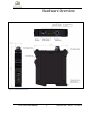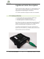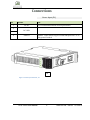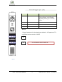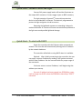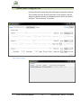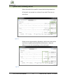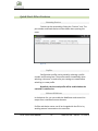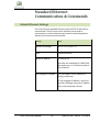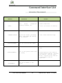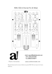
1
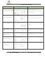
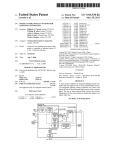
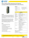
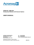
DCS Series - Lighting Controller USER MANUAL Contents Hardware Overview .................................................................. 2 Specifications & Features.......................................................... 3 Lighthead Cable Description ..................................................... 4 “C1” Cable Specifications .......................................................... 4 Connections .............................................................................. 5 Trigger Connection Diagrams ................................................... 8 Modes of Operation .................................................................. 9 Quick Start .............................................................................. 11 Quick Start: Connect Power and Light .................................. 12 Quick Start: To start with DHCP............................................ 12 Quick Start: To start with a Static IP Address: ...................... 13 Ethernet Web Server .............................................................. 19 Standard Ethernet Communication & Commands ................. 20 Default Ethernet Settings........................................................ 20 Command Structure ................................................................ 21 Command Interface List .......................................................... 22 Warranty Information ............................................................. 25 DCS-100E User Manual 1 1595-050126 REVB 7/21/2015 Hardware Overview Figure 1 - Installation and Interface DCS-100E User Manual 2 1595-050126 REVB 7/21/2015 Specifications & Features Parameters Details Notes Input Power 24VDC Nominal, 4.5A 30VDC absolute maximum – exceeding 30VDC may result in damage to the controller Output Power 90W 1.5A continuous per channel 5A strobe per channel Channel Control [3] Independently adjustable Channels Modes Pulsed, Continuous, or Gated Continuous Trigger 5-30VDC, Opto-Isolated inputs [3] Individual trigger inputs Trigger-Pulse-Latency 10usec 24V typical trigger input Pulse-Width Range (Pulsed) 10usec – 65msec 1usec steps Pulse-Delay 1usec-10msec 1usec steps Duty Cycle 10% pulsed >10% gated-continuous Ambient Operating Temperature Range -10 to 125F Maximum Operating Temperature (case) 135 F Features Details 10/100 Ethernet Standard Ethernet (TCP-IP, UDP) Software - Windows-based GUI - Software .dlls in C# and C++ - LabView VI and drivers - Web Server Control applet DCS-100E User Manual Notes 3 Web server runs on most modern web browers. 1595-050126 REVB 7/21/2015 Lighthead Cable Description The DCS controller requires a light with a “C1” power designator. This cable contains our proprietary Signatech protection scheme and is programmed for the specific light it is connected to. A “C1” Suffix is required to the light part number to be compatable. “C1” Cable Specifications 5-Position M12, Male, Reverse (B) Coded, 22AWG Leads Standard PVC jacket, shielded (foil with drain) Embedded SignatechTM molded into the jacket (pin 5) Note: Without this cable and an appropriately programed SignatechTM signature, the controller will not function. This is a safety feature to prevent unwanted damage to the Lighthead or controller. It is possible to bypass Signatech TM by using an authorized set of Signatch data and a software key provided by Advanced Illumination. Contact the factory for more information. Figure 2 – Controller with C1 Cable DCS-100E User Manual 4 1595-050126 REVB 7/21/2015 Connections Power Input (P1) Pin Function 1 Note 24V DC 4.5A recommended minimum for best performance. 2 3 4 DC GND SHIELD Optional: Tied to chassis copper for ESD/EMI protection. Tie to earth ground if needed. P1 Figure 3 – Power input Connector, P1 DCS-100E User Manual 5 1595-050126 REVB 7/21/2015 External Trigger Input (P2) Pin Function Note 1 COMMON Common path for all trigger inputs Tie to a voltage level or ground depending on the type of external trigger 2 TRIGGER 1 3 TRIGGER 2 4 TRIGGER 3 Notes: ~Trigger Inputs are bi-directional opto-isolated. ~All inputs are TTLcompliant, and are rated to +30VDC P2 P3 P3 IS RESERVED FOR FUTURE USE Figure 4 DCS-100E User Manual 6 1595-050126 REVB 7/21/2015 Front Panel LED Color LED Behavior Function 1 Green Solid Main power is connected 2 Amber Off No light is connected Blinking @ 2Hz Heartbeat, device is ready Blinks twice Command received Off External trigger signal is low On External trigger signal is high 3, 4, 5 Yellow BUTTON Type Button Behavior Function 1 SPST Push Push and Release Resets the Device to Factory settings. Erases all EEPROM memory and sets the IP Address back to default. Figure 5 – Front Panel DCS-100E User Manual 7 1595-050126 REVB 7/21/2015 Trigger Connection Diagrams Figure 6 - Typical NPN / Emitter-Follower Connection Figure 7 - Typical NPN / Sinking Connection DCS-100E User Manual 8 1595-050126 REVB 7/21/2015 Modes of Operation Continuous Continuous mode provides continuous illumination at the desired current. Light is always on unless a user issues a command to shut it off or the power is disconnected. Power is limited by the type of light that is connected and by the total power dissipation of the controller. Limits are determined by SignatechTM. It is not required to manually limit settings to protect the controller or light. Strobe Strobe mode illumination is triggered by an external signal. Trigger-to-Pulse delay is 10 usec Pulsewidths is available from 1usec to 64msec, and can be attached independently to each channel. Delay is available from 1us to 10ms. It is possible to map triggers together or independently. Important Note: Pulse Skipping When the maximum trigger frequency is exceeded, the controller will “skip” pulses in order to maintain a safe duty cycle. This may appear as dark image acquisitions (missed triggers) or unstable flickering. Double-check your frequency and compare it to the maximum reported from the controller if this occurs. Reduce your current or shorten your pulsewidth to increase the maximum frequency if required. DCS-100E User Manual 9 1595-050126 REVB 7/21/2015 Gated Continuous This mode produces continuous illumination at the desired current, but the output follows the on-time of the external trigger signal. This mode is most useful to turn the light off during processes or in between inspections, or when longer pulse widths than pulsed mode will allow are needed. Trigger-to-Pulse delay is 10 usec Figure 8 - Typical Gated Operation DCS-100E User Manual 10 1595-050126 REVB 7/21/2015 Quick Start Typical Hardware Layout Light with “C1” Type Cable P1-Power P2-Trigger Figure 9 - Typical Hardware Setup For proper operation, make sure all connections are secure before applying power. DCS-100E User Manual 11 1595-050126 REVB 7/21/2015 Quick Start: Connect Power and Light Connect 24V power supply leads to P1 and the illuminator to the output M12 connector. Connect trigger inputs to P2 if necessary. The Light contains a SignatechTM current-drive protection device in the molded M12 connector. This device is programmed to protect the light and govern the drive current. Removing the lighthead connector or extending it beyond a maximum distance of 3 meters will cause communication problems to the light source and possible lighthead damage. Quick Start: To start with DHCP Power the controller with the Ethernet cable connected to a network. The controller will automatically be assigned an IP address by the network hardware. The controller will default to using DHCP when it is available. Optional: After initially connecting to the controller, the user can supply a custom IP address by sending a UDP packet command with the new IP address. See the command table for proper usage of the commands. If the user enters a custom IP address, it will begin using that address upon startup. If a static-IP address has been entered into EEPROM by a user, it will no longer use DHCP unless the EEPROM is cleared by a “RESET” command DCS-100E User Manual 12 1595-050126 REVB 7/21/2015 Quick Start: To start with a Static IP Address: Power the controller without an Ethernet cable connected, or connected directly to a PC. The controller will begin with a default IP address of 192.168.0.1 Make sure the PC is using a STATIC IP connection. To assign a static IP in Windows, change your adapter settings in your network configuration to use a static ip under IPV4 Settings, See FIGURE11. The static IP must be in the range of 192.168.0.XXX to work properly. Typically it is NOT required to use a cross-over cable, but maybe necessary for older machines. Figure 10 - Static IP Address Configuration DCS-100E User Manual 13 1595-050126 REVB 7/21/2015 Quick Start: Graphical User Interface (GUI) Installation Install the software using the provided DCS-Setup application. Installation requires Microsoft .NET framework 4.0 or later. Figure 11 - DCS Software Installer DCS-100E User Manual 14 1595-050126 REVB 7/21/2015 Quick Start: Using the GUI Pressing the devices drop-down box will ping the network for devices. The controller will scan for DCS controllers on the network, and will display any devices found in the dropdown menu. Select your device and press “Test Connection” to connect. Figure 12 & 13 - DCS GUI DCS-100E User Manual 15 1595-050126 REVB 7/21/2015 Quick Start: Enabling Modes Select the mode for the specific channel with the drop-down box All channels can operate in a mixture of any mode. There are no restrictions. Figure 14 Output current is governed by SignatechTM, which are current drive restrictions implemented by Advanced Illumination. Note the different current limits depending on the mode used. Figure 15 DCS-100E User Manual 16 1595-050126 REVB 7/21/2015 Continuous vs. Strobe Operation Strobe mode provides higher current limits than continuous. Using SignatechTM we can overdrive the output current higher. These values vary depending on the pulsewidth, current and type of light being used. In Strobe or Gated-Continuous modes, the output is triggered by an external device. Strobe mode uses a user-specified pulse-width and Gated-Continuous uses the input trigger width to determine the output pulse width. Pressing the “Pulse” button will send a software “trigger” command causing the light to pulse once. For pulsewidth and delay the units “ms” and “us” can be entered for milliseconds and microseconds respectively. Default units are msec. Figure 16 DCS-100E User Manual 17 1595-050126 REVB 7/21/2015 Quick Start: Other Features Renaming Devices: Devices can be renamed by clicking the “Devices” text. The part number and listed devices will be shown when opening this menu. Figure 17 Profiles: Configuration profiles can be saved by selecting a profile number and pressing save. The profiles switch immediately when selecting a new one, so make sure your settings are saved before switching to a new profile. By default, the last-used profile will be enabled when the controller is switched on. Ethernet WebServer In the devices list, you can enable the WebServer and control the output from a standard internet browser. Profiles and device names can all be changed with the GUI or by sending external commands to the controller. DCS-100E User Manual 18 1595-050126 REVB 7/21/2015 Ethernet Web Server After enabling the web server in the Software GUI, you can access the built-in web server from most internet browsers by entering the IP address of the controller in the browser address bar. Note that only the active configuration can be changed via the web server Figure 18 – Webserver UI DCS-100E User Manual 19 1595-050126 REVB 7/21/2015 Standard Ethernet Communication & Commands Default Ethernet Settings The Controller uses standard Ethernet protocol (TCP-IP and UDP) to communicate. The DCS control user interface can be used to communicate, or other software may be used to send data packets directly from the host to the controller. Setting Value Typical Port Settings UDP or TCP-IP, port 7777 DHCP Enabled by default Default IP Address 192.168.24.115 Controller will use default IP if DHCP fails upon power up, or if an Ethernet cable is not connected User Assigned IP Address User can assign a new IP address by sending a command If a user assigned IP address is used, the controller will begin using that IP address until a reset command is issued DCS-100E User Manual 20 1595-050126 REVB 7/21/2015 Command Structure The DCS100 uses an SCPI-like interface where commands are a series of readable strings with parameters separated by commas. The strings must be terminated by a semicolon (‘;’) for proper operation. Commands with a parameter Commands that require a parameter have it separated by a comma. Example: “SET:LEVEL, 100;” Where “SET:LEVEL” is the command and “100” is the parameter. Commands without a parameter If the command has no parameter, the command simply ends with a semicolon. Example: “*IDN?;” Commands are non-case sensitive, and spaces may be used between commands and parameters for readability. DCS-100E User Manual 21 1595-050126 REVB 7/21/2015 Command Interface List Information / Help commands COMMAND DESCRIPTION RETURNS Gets device information: firmware, hardware, etc.. “*IDN?;” “*CHANNEL:CONFIGS?" “*PROFILE:NUMBER?” Reports the current, pulsewidth, delay, and trigger map settings on all channels Advanced illumination “DCS-100: (fw version, hw version)” Returns an XML formatted string: Gets the active profile number Returns an XML formatted string: "*PROFILE:NAMES?" “*IP:ADDRESS?” Gets all the profile names saved in memory <profiles><profile id="0" name="0" /><profile id="1" name="1" /><profile id="2" name="2" /><profile id="3" name="3" /><profile id="4" name="4" /><profile id="5" name="5" /></profiles> Gets the IP address of the device DCS-100E User Manual 22 1595-050126 REVB 7/21/2015 Channel Control Commands COMMAND DESCRIPTION "SET:LEVEL:CHANNELc, nnnn" "SET:MODE:CHANNEL c, n;" "SET:TRIGGER:CHANNEL n;" c, RETURNS Sets the current in milliamps c = 1 - 3 nnnn = 0-1500 &gated) nnnn = 0-3000 Sets the mode (channel number) (continuous c = 0 - 3 n = 0 n = 1 n = 2 n = 3 continuous) (channel number) (off) (continuous) (strobe) (gated “SET:LEVEL:CHANNEL1, nnnn;” Where nnnn = 0-750 for continuous, 03000 for strobe (strobe) INFO: Channel “n” set to mode “x (xxx)” Sets the trigger edge c = 1 - 3 n = 0 n = 1 (channel number) (falling edge) (rising edge INFO: Channel “c” set to “xxxx edge” trigger. Sets the pulsewidth in usec "SET:WIDTH:CHANNEL nnnn;" c, "SET:DELAY:CHANNEL c, nnnn;" “MAP:TRIGGER:CHANNEL c, n” “TRIGGER:CHANNEL c” c = 1 - 3 (channel number) nnnn = 0-65,000 (us) Sets the pulse delay in usec c = 1 - 3 (channel number) nnnn = 0-10,000 (us) Maps the specified trigger to the specified channel c = 0 – 3 number) n = 0 – 3 number) INFO: Channel “c” pulse width set to “nnnn” us INFO: Channel “c” pulse delay set to “n” microseconds. (channel (trigger Generates a software trigger on the specified channel c = 0 – 3 number) DCS-100E User Manual (channel 23 1595-050126 REVB 7/21/2015 Utility Commands COMMAND DESCRIPTION "SAVE:PROFILE, n " Saves the profile in EEPROM n = 0-5 "LOAD:PROFILE" RETURNS INFO: Profile “n” has been saved. (profile number) Updates all settings to the chosen profile INFO: Name of profile 0 set to ' test' INFO: Name of profile “n” set to ‘xxxxxx’ "SET:PROFILE:NAME, xxxxxx" “SET:STATIC:IP, nnn.nnn.nnn.nnn;” “DISCONNECT” Saves a name to the current active profile Writes a static IP address into memory nnn = IP address separated by “.” Disconnects communication to the controller from the host Enables the built-in web-server “SET:WEB:CONFIG, n” “OVERRIDE:SIGNATECH” n = 0 (disabled) n = 1 (enabled) Overrides the external Signatech data. Must be used in conjunction with a Signatech-KEY provided by Advanced Illumination. DCS-100E User Manual 24 1595-050126 REVB 7/21/2015 Warranty Information Every Advanced illumination, Inc. (Ai) product is thoroughly inspected and tested before leaving the factory. Products are warranted to be free of defects in workmanship and materials for a period of two years from the original date of purchase. Should a defect develop during this period, please contact Ai Customer Service or your Ai distributor for a Return Merchandise Authorization (RMA), and return the complete product, freight prepaid, to Ai. Please provide a detailed description of the problem if possible. If a defect is found, Ai will - at our discretion - repair or replace the product without charge. Ai claims no liability for any implied warranties, including “merchantability” and “fitness for a specific purpose.” Electromagnetic Compatibility This product was tested and complies with the regulatory requirements and limits for electromagnetic compatibility (EMC) as stated in the product specifications. These requirements and limits are designed to provide reasonable protection against harmful interference only when the product is operated in its intended industrial electromagnetic environment. To minimize the potential for electromagnetic interference or unacceptable performance degradation, install and use this product in strict accordance with the instructions in the product documentation. Technical Support and Product Information Standard product info: www.advill.com Technical support [email protected] 440 State Garage Road, Rochester VT. 05767 © 2015 Advanced Illumination Inc. All rights reserved DCS-100E User Manual 25 1595-050126 REVB 7/21/2015