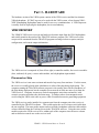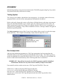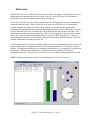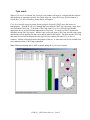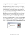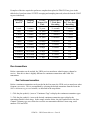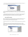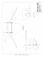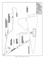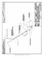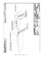
1
VEMCO VR28 SYSTEM
TRACK28 SOFTWARE
Version 2.0.1 6-12-2011
VEMCO, A Division of AMIRIX Systems Inc.
AMIRIX Systems Inc.
Warranty and Disclaimer
WARRANTY
AMIRIX Systems Inc., doing business under its trade name VEMCO, provides a one (1) year warranty period for the Product from date of shipment.
VEMCO warrants that on the date of shipment all Products manufactured by VEMCO are free from defects in material and workmanship under normal use and service. This warranty
applies to the components necessary for equipment upgrades, i.e. the VR1/VR2 to VR2W upgrade. With respect to transmitter products, while VEMCO is able to predict battery life with
some certainty, VEMCO cannot guarantee that these Products will remain functional while submerged for extended periods of time. This warranty does not apply to any equipment,
materials or design supplied by Buyer or a third party; re-battery services provided by VEMCO; Products for which VEMCO has not received payment; problems that results from:
external causes such as accident, abuse, misuse; servicing not authorized by VEMCO; usage not in accordance with Product instructions; failure to follow the Product instructions or
failure to perform preventative maintenance; usage of accessories, parts or components not supplied by VEMCO.
This warranty shall survive delivery only on the conditions and subject to the limitations set forth below.
NOTICE PERIODS
To receive a warranty remedy for a Product, Buyer must contact VEMCO’s Customer Support Department during the warranty period to receive the Return Material Authorization
(“RMA”) instructions. Each defective Product returned for warranty remedy must be shipped at the Buyer’s expense according to the RMA instructions and must include reasonable
proof that the claimed defect is due to a matter embraced within the warranty set forth above and that such defect did not result from any act or omission of Buyer, including but not
limited to any failure to operate and maintain the Product in accordance with VEMCO’s applicable written instructions.
REMEDY
VEMCO’s liability, and the Buyer’s exclusive remedy under this warranty, as to a defect in material or workmanship, is limited to the repair of such defect in the accessory, equipment or
part in which the defect appears or, at VEMCO’s option, to the replacement of such accessory, equipment or part with a similar item free from defect. As to any item repaired by VEMCO
or furnished as a replacement by VEMCO, VEMCO’s liability and the Buyer’s exclusive remedy to the repair or replacement of such item for any further defect in material or
workmanship, provided VEMCO receives written notice at Halifax, Nova Scotia, of such further defect from BUYER within ninety (90) days after the repaired or replaced item is shipped
to BUYER and provided that BUYER returns same to VEMCO as provided under “Notice Periods”.
RETURNED ITEMS
All repairs, replacements and corrections described above shall be performed by VEMCO at its plant at Halifax, Nova Scotia, or at such other place as may be mutually agreeable, and
with reasonable care and dispatch in order that the Product, accessory, equipment or part will not be kept out of service longer than necessary. Return to BUYER of a repaired,
replacement, or corrected accessory, equipment, part or Product shall be at VEMCO’s expense. Title to and risk of loss of the Product, accessory, equipment, or part returned to
VEMCO pursuant hereto shall at all times remain with the BUYER, except that title to a returned accessory, equipment, part, or Product shall pass to VEMCO concurrently with
shipment to BUYER of any item furnished by VEMCO to BUYER as a replacement therefore. VEMCO shall have only such responsibility for any Product, accessory, equipment, or part
owned by the BUYER and in the possession of VEMCO as is chargeable by law to a bailee for hire, but shall not be chargeable for loss of use thereof.
WEAR AND TEAR
Normal wear and tear and the need for regular maintenance shall not constitute a defect under this warranty.
DISCLAIMER AND RELEASE
THE WARRANTIES, OBLIGATIONS AND LIABILITIES OF VEMCO AND THE REMEDIES OF BUYER SET FORTH HEREIN ARE EXCLUSIVE AND IN SUBSTITUTION FOR, AND
BUYER HEREBY WAIVES AND RENOUNCES, ALL OTHER WARRANTIES AND OBLIGATIONS OF VEMCO AND ANY ASSIGNEE OF VEMCO AND ALL RIGHTS, CLAIMS AND
REMEDIES OF BUYER AGAINST VEMCO, EXPRESS OR IMPLIED, ARISING BY LAW OR OTHERWISE, WITH RESPECT TO ANY NON-PERFORMANCE OR DEFECT IN THE
PRODUCT OR IN ANY OTHER THING DELIVERED UNDER THIS AGREEMENT, INCLUDING BUT NOT LIMITED TO:
(A)
(B)
(C)
(D)
(E)
ANY IMPLIED WARRANTY OF MERCHANTABILITY OR FITNESS FOR A PARTICULAR PURPOSE;
ANY IMPLIED WARRANTY ARISING OUT OF COURSE OF PERFORMANCE, COURSE OF DEALING OR USAGE OF TRADE;
ANY OBLIGATION, LIABILITY, CLAIM OR REMEDY IN TORT, WHETHER OR NOT ARISING FROM THE NEGLIGENCE OF VEMCO OR ANY ASSIGNEE OF VEMCO,
ACTUAL OR IMPUTED;
ANY OBLIGATION, LIABILITY, RIGHT, CLAIM, OR REMEDY FOR LOSS OF OR DAMAGE TO THE PRODUCT, FOR LOSS OF USE, REVENUE, OR PROFIT WITH RESPECT
TO THE PRODUCT; OR FOR ANY OTHER DIRECT, INCIDENTAL OR CONSEQUENTIAL DAMAGES; AND
VEMCO MAKES NO REPRESENTATION THAT THE PRODUCT WILL NOT INFRINGE ANY PATENT OR OTHER RIGHTS OF ANY PERSON AND BUYER AGREES TO
INDEMNIFY VEMCO AND HOLD VEMCO HARMLESS FROM ANY AND ALL CLAIMS AND LIABILITIES WITH RESPECT TO SAME TOGETHER WITH ANY CLAIMS AND
LIABILITIES WITH RESPECT TO ANY INFRINGEMENT OF ANY PATENT OR OTHER RIGHTS OF ANY PERSON ARISING AS A RESULT OF BUYER'S PRODUCTS,
TECHNOLOGY, ACTIVITIES, OR OTHERWISE.
LICENSE AGREEMENT
VEMCO grants to the Buyer a limited, personal license, with no right to sub-license, to use the Intellectual Property (“IP”) and Embedded Software in the manner set out in the
Documentation. The Embedded Software and IP are not sold to Buyer. All property rights, including Intellectual Property Rights, remain with VEMCO. All rights related to the Embedded
Software not expressly licensed to the Buyer are reserved to VEMCO. BUYER shall not permit any person other than BUYER and its employees to use or make use of the Embedded
Software and/or IP. BUYER shall not, and shall not permit any third party to, modify, adapt, translate, reverse engineer, decompile, disassemble, or create derivative works based on
the Embedded Software and/or IP. This license is assigned to the Product with which you have acquired the Embedded Software and/or IP. If the Product purchased is a Transmitter
product, be advised that the license life is equal to the operational life.
EXPORT
Products and associated materials supplied or licensed hereunder may be subject to various export laws and regulations. It is the responsibility or BUYER to comply with such laws and
regulations.
NEGOTIATED AGREEMENT
It is fully understood by the parties that the price of the Product and other mutual agreements of the parties set forth in this agreement were arrived at in consideration of this warranty,
SPECIFICALLY INCLUDING THE WAIVER, RELEASE AND RENUNCIATION BY BUYER SET FORTH ABOVE (DISCLAIMER AND RELEASE).
© (2011) AMIRIX Systems Inc. All rights reserved. The information contained herein includes
information which is confidential and proprietary to AMIRIX Systems Inc. and may not be used or
disclosed without prior written consent of AMIRIX Systems Inc.
DOC-4498-06
TABLE OF CONTENTS
Part 1 - INTRODUCTION . . . . . . . . . . . . . . . . . . . . . . . . . . . . . . . . . . . . . . . . . . . . . . . . . . . . . . . 1
About VEMCO . . . . . . . . . . . . . . . . . . . . . . . . . . . . . . . . . . . . . . . . . . . . . . . . . . . . . . . . . 1
System Overview . . . . . . . . . . . . . . . . . . . . . . . . . . . . . . . . . . . . . . . . . . . . . . . . . . . . . . . . 1
Using this manual . . . . . . . . . . . . . . . . . . . . . . . . . . . . . . . . . . . . . . . . . . . . . . . . . . . . . . . 2
What’s new . . . . . . . . . . . . . . . . . . . . . . . . . . . . . . . . . . . . . . . . . . . . . . . . . . . . . . . . . . . . 2
Part 2 - USING THE VR28 SYSTEM . . . . . . . . . . . . . . . . . . . . . . . . . . . . . . . . . . . . . . . . . . . . . 3
Set up hardware equipment . . . . . . . . . . . . . . . . . . . . . . . . . . . . . . . . . . . . . . . . . . . . . . . . 3
Set up software program . . . . . . . . . . . . . . . . . . . . . . . . . . . . . . . . . . . . . . . . . . . . . . . . . . 3
Use the system . . . . . . . . . . . . . . . . . . . . . . . . . . . . . . . . . . . . . . . . . . . . . . . . . . . . . . . . . . 4
View data . . . . . . . . . . . . . . . . . . . . . . . . . . . . . . . . . . . . . . . . . . . . . . . . . . . . . . . . . . . . . . 5
Part 3 - HARDWARE . . . . . . . . . . . . . . . . . . . . . . . . . . . . . . . . . . . . . . . . . . . . . . . . . . . . . . . . . . 6
VR28 RECEIVER . . . . . . . . . . . . . . . . . . . . . . . . . . . . . . . . . . . . . . . . . . . . . . . . . . . . . . . 6
Placement on Ship . . . . . . . . . . . . . . . . . . . . . . . . . . . . . . . . . . . . . . . . . . . . . . . . . 6
BNC Coax Cable Installation . . . . . . . . . . . . . . . . . . . . . . . . . . . . . . . . . . . . . . . . 7
Audio Connection . . . . . . . . . . . . . . . . . . . . . . . . . . . . . . . . . . . . . . . . . . . . . . . . . 8
Mono Audio Output . . . . . . . . . . . . . . . . . . . . . . . . . . . . . . . . . . . . . . . . . . 8
Stereo Audio Output . . . . . . . . . . . . . . . . . . . . . . . . . . . . . . . . . . . . . . . . . 8
Computer Connection . . . . . . . . . . . . . . . . . . . . . . . . . . . . . . . . . . . . . . . . . . . . . 10
Power Supply Connection . . . . . . . . . . . . . . . . . . . . . . . . . . . . . . . . . . . . . . . . . . 10
VH4x HYDROPHONE . . . . . . . . . . . . . . . . . . . . . . . . . . . . . . . . . . . . . . . . . . . . . . . . . . 11
Connection of Hydrophone Cable to VR28 Receiver . . . . . . . . . . . . . . . . . . . . . 12
VFIN DEPLOYMENT METHOD . . . . . . . . . . . . . . . . . . . . . . . . . . . . . . . . . . . . . . . . . 13
VFIN Hydrophone Cable . . . . . . . . . . . . . . . . . . . . . . . . . . . . . . . . . . . . . . . . . . . 13
Hydrophone Connection to VFIN . . . . . . . . . . . . . . . . . . . . . . . . . . . . . . 13
Care of Underwater Connections . . . . . . . . . . . . . . . . . . . . . . . . . . . . . . . . . . . . . 15
VFIN Deployment Methods . . . . . . . . . . . . . . . . . . . . . . . . . . . . . . . . . . . . . . . . 15
Suggested Deployment Method . . . . . . . . . . . . . . . . . . . . . . . . . . . . . . . . 16
Alternative Deployment Method 1 . . . . . . . . . . . . . . . . . . . . . . . . . . . . . 16
Alternative Deployment Methods for Small Ships . . . . . . . . . . . . . . . . . 16
VFIN Speed of Tow . . . . . . . . . . . . . . . . . . . . . . . . . . . . . . . . . . . . . . . . . . . . . . . 17
Part 4 - SOFTWARE . . . . . . . . . . . . . . . . . . . . . . . . . . . . . . . . . . . . . . . . . . . . . . . . . . . . . . . . . . 18
USING THE SOFTWARE
. . . . . . . . . . . . . . . 18
Introduction . . . . . . . . . . . . . . . . . . . . . . . . . . . . . . . . . . . . . . . . . . . . . . . . . . . . . 18
Getting Started . . . . . . . . . . . . . . . . . . . . . . . . . . . . . . . . . . . . . . . . . . . . . . . . . . . 18
System Requirements . . . . . . . . . . . . . . . . . . . . . . . . . . . . . . . . . . . . . . . . 19
Software Installation . . . . . . . . . . . . . . . . . . . . . . . . . . . . . . . . . . . . . . . . 19
FILE MENU . . . . . . . . . . . . . . . . . . . . . . . . . . . . . . . . . . . . . . . . . . . . . . . . . . . . . . . . . . 20
Data Directory . . . . . . . . . . . . . . . . . . . . . . . . . . . . . . . . . . . . . . . . . . . . . . . . . . . 20
File size . . . . . . . . . . . . . . . . . . . . . . . . . . . . . . . . . . . . . . . . . . . . . . . . . . . . . . . . 21
Print profile . . . . . . . . . . . . . . . . . . . . . . . . . . . . . . . . . . . . . . . . . . . . . . . . . . . . . 21
Print setup . . . . . . . . . . . . . . . . . . . . . . . . . . . . . . . . . . . . . . . . . . . . . . . . . . . . . . 22
Exit . . . . . . . . . . . . . . . . . . . . . . . . . . . . . . . . . . . . . . . . . . . . . . . . . . . . . . . . . . . . 22
SETUP MENU . . . . . . . . . . . . . . . . . . . . . . . . . . . . . . . . . . . . . . . . . . . . . . . . . . . . . . . . . 22
Positioning system . . . . . . . . . . . . . . . . . . . . . . . . . . . . . . . . . . . . . . . . . . . . . . . . 22
GPS setup . . . . . . . . . . . . . . . . . . . . . . . . . . . . . . . . . . . . . . . . . . . . . . . . . 22
Baud . . . . . . . . . . . . . . . . . . . . . . . . . . . . . . . . . . . . . . . . . . . . . . . 23
Sound bell on update . . . . . . . . . . . . . . . . . . . . . . . . . . . . . . . . . . 23
Scanning cycle
. . . . . . . . . . . . . . . . . . . . . . . . . . . 23
Com port
. . . . . . . . . . . . . . . . . . . . . . . . . . . . . . . . . 23
Data bits, Stop bits, and Parity
. . . . . . . . . . . . . . . 23
GPS Data to Save
. . . . . . . . . . . . . . . . . . . . . . . . . . . 24
Gyro Compass setup . . . . . . . . . . . . . . . . . . . . . . . . . . . . . . . . . . . . . . . . 24
Baud . . . . . . . . . . . . . . . . . . . . . . . . . . . . . . . . . . . . . . . . . . . . . . . 24
Sound bell on update . . . . . . . . . . . . . . . . . . . . . . . . . . . . . . . . . 24
. . . . . . . . . . . . . . . . . . . . . . . . . . . . . . . . . . . . . . . . . . . . . . . . . . . 24
Scanning cycle
. . . . . . . . . . . . . . . . . . . . . . . . . . . 25
Com port
. . . . . . . . . . . . . . . . . . . . . . . . . . . . . . . . . 25
Data bits, Stop bits, and Parity
. . . . . . . . . . . . . . . 25
Gyro data to save . . . . . . . . . . . . . . . . . . . . . . . . . . . . . . . . . . . . . 25
Receiver . . . . . . . . . . . . . . . . . . . . . . . . . . . . . . . . . . . . . . . . . . . . . . . . . . . . . . . . 26
Tag Setup . . . . . . . . . . . . . . . . . . . . . . . . . . . . . . . . . . . . . . . . . . . . . . . . . . . . . . . 26
Continuous Tag Setup . . . . . . . . . . . . . . . . . . . . . . . . . . . . . . . . . . . . . . . 26
Add Continuous Tag . . . . . . . . . . . . . . . . . . . . . . . . . . . . . . . . . . 26
View Continuous Tag . . . . . . . . . . . . . . . . . . . . . . . . . . . . . . . . . 28
Edit Continuous Tag . . . . . . . . . . . . . . . . . . . . . . . . . . . . . . . . . . 29
Delete Continuous Tag . . . . . . . . . . . . . . . . . . . . . . . . . . . . . . . . 30
Coded Tag Setup . . . . . . . . . . . . . . . . . . . . . . . . . . . . . . . . . . . . . . . . . . . 30
Coded Frequency Setup . . . . . . . . . . . . . . . . . . . . . . . . . . . . . . . . 31
Coded Channel Setup . . . . . . . . . . . . . . . . . . . . . . . . . . . . . . . . . . 34
Coded Telemetry Setup . . . . . . . . . . . . . . . . . . . . . . . . . . . . . . . . 35
CHAT Tag Setup . . . . . . . . . . . . . . . . . . . . . . . . . . . . . . . . . . . . . . . . . . . 39
Add CHAT Tag . . . . . . . . . . . . . . . . . . . . . . . . . . . . . . . . . . . . . . 39
View CHAT Tag . . . . . . . . . . . . . . . . . . . . . . . . . . . . . . . . . . . . . 41
Edit CHAT Tag . . . . . . . . . . . . . . . . . . . . . . . . . . . . . . . . . . . . . . 42
Delete CHAT Tag . . . . . . . . . . . . . . . . . . . . . . . . . . . . . . . . . . . . 43
Decoding setup . . . . . . . . . . . . . . . . . . . . . . . . . . . . . . . . . . . . . . . . . . . . . . . . . . 43
AGC sensitivity . . . . . . . . . . . . . . . . . . . . . . . . . . . . . . . . . . . . . . . . . . . . 44
Bearing . . . . . . . . . . . . . . . . . . . . . . . . . . . . . . . . . . . . . . . . . . . . . . . . . . . 44
Use moving average . . . . . . . . . . . . . . . . . . . . . . . . . . . . . . . . . . . 44
Samples to hold / Samples to average . . . . . . . . . . . . . . . . . . . . . 44
Signal options . . . . . . . . . . . . . . . . . . . . . . . . . . . . . . . . . . . . . . . . . . . . . 45
No signal redraw delay . . . . . . . . . . . . . . . . . . . . . . . . . . . . . . . . 45
Gain danger level . . . . . . . . . . . . . . . . . . . . . . . . . . . . . . . . . . . . . 45
Sound travel . . . . . . . . . . . . . . . . . . . . . . . . . . . . . . . . . . . . . . . . . . . . . . . 45
Compass setup . . . . . . . . . . . . . . . . . . . . . . . . . . . . . . . . . . . . . . . . . . . . . . . . . . . 46
Profile setup . . . . . . . . . . . . . . . . . . . . . . . . . . . . . . . . . . . . . . . . . . . . . . . . . . . . . 46
VIEW MENU . . . . . . . . . . . . . . . . . . . . . . . . . . . . . . . . . . . . . . . . . . . . . . . . . . . . . . . . . 47
WINDOW MENU . . . . . . . . . . . . . . . . . . . . . . . . . . . . . . . . . . . . . . . . . . . . . . . . . . . . . . 47
RUN MENU . . . . . . . . . . . . . . . . . . . . . . . . . . . . . . . . . . . . . . . . . . . . . . . . . . . . . . . . . . 48
Testing System . . . . . . . . . . . . . . . . . . . . . . . . . . . . . . . . . . . . . . . . . . . . . . . . . . . 48
Run transponders . . . . . . . . . . . . . . . . . . . . . . . . . . . . . . . . . . . . . . . . . . . . . . . . . 48
Initialize transponder . . . . . . . . . . . . . . . . . . . . . . . . . . . . . . . . . . . . . . . . 49
Global search . . . . . . . . . . . . . . . . . . . . . . . . . . . . . . . . . . . . . . . . . . . . . . 50
Cycle search . . . . . . . . . . . . . . . . . . . . . . . . . . . . . . . . . . . . . . . . . . . . . . . 51
Real time track . . . . . . . . . . . . . . . . . . . . . . . . . . . . . . . . . . . . . . . . . . . . . 52
Upload track . . . . . . . . . . . . . . . . . . . . . . . . . . . . . . . . . . . . . . . . . . . . . . . 52
Run transmitters . . . . . . . . . . . . . . . . . . . . . . . . . . . . . . . . . . . . . . . . . . . . . . . . . . 54
Run Continuous transmitters . . . . . . . . . . . . . . . . . . . . . . . . . . . . . . . . . . 54
Run Coded 200 Transmitters . . . . . . . . . . . . . . . . . . . . . . . . . . . . . . . . . . 55
Tracking window . . . . . . . . . . . . . . . . . . . . . . . . . . . . . . . . . . . . . . . . . . . . . . . . . 56
Gyro Compass data window . . . . . . . . . . . . . . . . . . . . . . . . . . . . . . . . . . 58
Profile window . . . . . . . . . . . . . . . . . . . . . . . . . . . . . . . . . . . . . . . . . . . . . 59
Features . . . . . . . . . . . . . . . . . . . . . . . . . . . . . . . . . . . . . . . . . . . . 60
HELP MENU . . . . . . . . . . . . . . . . . . . . . . . . . . . . . . . . . . . . . . . . . . . . . . . . . . . . . . . . . . 60
Help topics . . . . . . . . . . . . . . . . . . . . . . . . . . . . . . . . . . . . . . . . . . . . . . . . . . . . . . 60
Contents . . . . . . . . . . . . . . . . . . . . . . . . . . . . . . . . . . . . . . . . . . . . . . . . . . 60
Index . . . . . . . . . . . . . . . . . . . . . . . . . . . . . . . . . . . . . . . . . . . . . . . . . . . . 61
Find . . . . . . . . . . . . . . . . . . . . . . . . . . . . . . . . . . . . . . . . . . . . . . . . . . . . . 61
How to Use Help . . . . . . . . . . . . . . . . . . . . . . . . . . . . . . . . . . . . . . . . . . . . . . . . . . . . . . . 61
About... . . . . . . . . . . . . . . . . . . . . . . . . . . . . . . . . . . . . . . . . . . . . . . . . . . . . . . . . . 61
Part 5 - OUTPUT FILES . . . . . . . . . . . . . . . . . . . . . . . . . . . . . . . . . . . . . . . . . . . . . . . . . . . . . . . 62
TRANSMITTER DATA FILES . . . . . . . . . . . . . . . . . . . . . . . . . . . . . . . . . . . . . . . . . . . 62
Continuous transmitter data files . . . . . . . . . . . . . . . . . . . . . . . . . . . . . . . . . . . . . 62
Pinger data file . . . . . . . . . . . . . . . . . . . . . . . . . . . . . . . . . . . . . . . . . . . . . 63
One Channel Telemetry data file . . . . . . . . . . . . . . . . . . . . . . . . . . . . . . . 63
Two Channel Telemetry data file . . . . . . . . . . . . . . . . . . . . . . . . . . . . . . 64
Coded transmitter data files . . . . . . . . . . . . . . . . . . . . . . . . . . . . . . . . . . . . . . . . . 65
Files From Transponders . . . . . . . . . . . . . . . . . . . . . . . . . . . . . . . . . . . . . . . . . . . . . . . . . 68
Real time data file . . . . . . . . . . . . . . . . . . . . . . . . . . . . . . . . . . . . . . . . . . . . . . . . 68
Log file . . . . . . . . . . . . . . . . . . . . . . . . . . . . . . . . . . . . . . . . . . . . . . . . . . . . . . . . . 70
Archive file . . . . . . . . . . . . . . . . . . . . . . . . . . . . . . . . . . . . . . . . . . . . . . . . . . . . . 71
Positioning System Enabled . . . . . . . . . . . . . . . . . . . . . . . . . . . . . . . . . . . . . . . . . . . . . . 73
GPS Enabled Files . . . . . . . . . . . . . . . . . . . . . . . . . . . . . . . . . . . . . . . . . . . . . . . . 73
Gyro Compass Enabled Files . . . . . . . . . . . . . . . . . . . . . . . . . . . . . . . . . . . . . . . . 74
Part 6 - APPENDIXES . . . . . . . . . . . . . . . . . . . . . . . . . . . . . . . . . . . . . . . . . . . . . . . . . . . . . . . . 75
Appendix A - TROUBLE SHOOTING . . . . . . . . . . . . . . . . . . . . . . . . . . . . . . . . . . . . . . 75
Appendix B - HARDWARE SPECIFICATIONS . . . . . . . . . . . . . . . . . . . . . . . . . . . . . . 77
VR28 Controller Module Specifications . . . . . . . . . . . . . . . . . . . . . . . . . . . . . . . 77
VR21 Receiver Module Specifications . . . . . . . . . . . . . . . . . . . . . . . . . . . . . . . . 78
Appendix C - CORTLAND INSTRUCTIONS . . . . . . . . . . . . . . . . . . . . . . . . . . . . . . . . 79
Cortland Stopper Installation Procedure . . . . . . . . . . . . . . . . . . . . . . . . . . . . . . . 79
How to Fabricate an Eye Splice Termination . . . . . . . . . . . . . . . . . . . . . . . . . . . 81
Appendix D - HARDWARE DIAGRAMS . . . . . . . . . . . . . . . . . . . . . . . . . . . . . . . . . . . 84
GLOSSARY . . . . . . . . . . . . . . . . . . . . . . . . . . . . . . . . . . . . . . . . . . . . . . . . . . . . . . . . . . 96
INDEX . . . . . . . . . . . . . . . . . . . . . . . . . . . . . . . . . . . . . . . . . . . . . . . . . . . . . . . . . . . . . . . 98
Part 1 - INTRODUCTION
About VEMCO
VEMCO, a division of AMIRIX Systems Incorporated, is a leader in the design and manufacture
of oceanographic research tools and systems since 1979. Now located in Halifax, Nova Scotia,
VEMCO's product line ranges from miniature acoustic transmitters and data loggers to large
tracking, positioning, and monitoring systems.
Please contact us at:
VEMCO Division
AMIRIX Systems Inc.
211 Horseshoe Lake Drive
Halifax, Nova Scotia
Canada B3S 0B9
Phone: +1-902-450-1700
Fax: +1-902-450-1704
Web: www.vemco.com
System Overview
The VR28 system was developed by VEMCO Limited to locate and track tagged marine wildlife.
Once the tag is located, information such as temperature, pressure, and possibly swim speed
(depending on the type of tag) can be gathered. The system consists of a VR28 receiver, a four
element VH4x Hydrophone, and the appropriate cabling. A VFIN Depressor is often used for
deploying the hydrophone, but is optional. The system is controlled by the TRACK28 software
program running under Windows © 98 or Windows XP © on an IBM compatible computer.
The VR28 system has been designed to be operated from a ship and has a simple method of
displaying and storing data. The tracking screen in the TRACK28 software allows easy
identification that a signal has been received, as well as the bearing to the tag. Data is displayed
on the tracking screen and stored to an output file for later analysis.
The VR28 system can be used with CHAT tags by using the VH4x-XPD Transponding
Hydrophone with the VR28 receiver. CHAT tags are capable of storing data to an internal
memory to be acoustically retrieved at a later time. The data includes temperature and depth,
with an option of swim speed (see the CHAT tag section of Appendix A for more details).
VEMCO - VR28 SYSTEM MANUAL - PAGE 1
Using this manual
This manual is a user’s guide for the VR28 system, both the VR28 hardware and the TRACK28
software.
This manual was designed for both new and experienced users. Begin with “Part 2 - Using the
VR28 System”, which is a list of necessary tasks to perform given in step form. Each of these
tasks is described in greater detail later in the manual, and the related section is named in the list.
If you’re new to the TRACK28 system, read the “Using the VR28 System” section and each
related section mentioned there. This will give you a good foundation. If you’re familiar with the
VR28 system, the “Using the VR28 System” section can act as a review or check list.
All of the information contained in “Part 4 - Software” and “Part 5 - Output Files” of this manual
is also contained in the help file for the TRACK28 software. This can be very useful when the
manual is not available and is accessed by selecting “Help Topics” in the Help menu. For
assistance with using Help Topics, select “How to Use Help” in the Help menu.
The following precaution terms are used throughout the manual and are defined below.
DANGER - could lead to serious injury or loss of life if readers do not know what they are doing.
WARNING - could result in damage to the product if the procedures are not followed accurately.
CAUTION - could result in faulty results if the reader does not follow the procedure correctly.
NOTE - used to alert readers to potential problems.
ADVICE - suggestions that would make the reader’s work easier.
What’s new
This version of TRACK28 for Windows is based on the previous version. The major changes
are the addition of Coded 200 compatibility and sizable tracking windows. Because the coded
portion of the software has changed to accommodate Coded 200, the output files for coded
transmitters have also changed in their format.
VEMCO - VR28 SYSTEM MANUAL - PAGE 2
Part 2 - USING THE VR28 SYSTEM
The list below gives the correct steps and order needed to correctly use the VR28 system. Each
step includes the name of the section in this manual which contains more details about that step.
1. Set up hardware equipment:
a. Select a suitable location for the receiver and computer (see “Placement on Ship” in the
VR28 Receiver section of the Hardware part of the manual).
b. Connect the four VR21 inputs (marked IN) to the corresponding connectors on the VR28
HYDROPHONE INPUT MODULE with the supplied BNC cables (see “BNC Coax
Cable Installation” in the VR28 Receiver section of the Hardware part of the manual). Be
sure the bow VR21 receiver modular is connected to the bow hydrophone connector,
starboard to starboard, aft to aft, port to port.
c. Connect the VH4x hydrophone to the connector marked QUAD HYDROPHONE on the
VR28 receiver (bottom right corner). See “Connection of Hydrophone Cable to VR28
Receiver” in the VH4x Hydrophone section of the Hardware part of the manual)
d. Connect the serial port of the computer with TRACK28 installed on it to the DB-9
connector marked RS232 SERIAL I/O on the VR28 receiver with a RS232 cable (see
“Computer Connection” in the VR28 Receiver section of the Hardware part of the
manual).
e. Connect a 12 VDC power supply to the connector on the VR28 receiver marked 12VDC
POWER (see “Power Supply Connection” in the VR28 Receiver section of the Hardware
part of the manual).
f. Connect the positioning system to the computer (if applicable).
g. Deploy the hydrophone, if not doing in-air tests (see “VFIN Deployment Method” in the
Hardware part of this manual).
2. Set up software program:
a. Install the Track28 software on an appropriate computer (see “Using the Software” in the
Software part of this manual).
b. Enter the computer serial port number to which the VR28 receiver is connected into the
software (see “Receiver” in the Setup menu of the Software part of this manual).
c. Setup and enable the positioning system in the software, if applicable. See “Position
System” in the Setup menu of the Software part of this manual).
d. Enter the information pertaining to the tags in Tag Setup (see Setup menu in the Software
part of this manual).
e. Setup the decoding information in Decoding Setup (see Setup menu in the Software part
of this manual).
VEMCO - VR28 SYSTEM MANUAL - PAGE 3
3. Use the system::
These functions are only available if the VR28 hardware (Step 1) and TRACK28 software (Step
2) are properly setup.
NOTE: It is strongly suggested to test the transmitters and CHAT tags being used with the
VR28 system on dry land before deploying the tags. This will verify the tag
information is correctly entered in the TRACK28 software (see “Tag Setup” in the
Setup menu in the Software part of this manual).
a. Select the desired function and the corresponding Run menu selection from the list below.
b. Perform the function by following the instructions in the appropriate section in the Run
menu part of this manual.
HINT: To search for deployed CHAT tags, use Global search to verify that CHAT tags are
in the area then use Cycle search to identify the CHAT tags present by their ID number(s).
c. Close the Tracking Form window when the desired function is completed. This will end
the study.
Desired Function to Perform
Run Menu Selection
1. Initialize a CHAT tag to collect and store data to memory
Transponders J Initialize
2. Search for the presence of any CHAT tags in the area
Transponders J Global search
3. Identify which CHAT tags are in the area
Transponders J Cycle search
4. Track a CHAT tag and collect data in real time
Transponders J Real time track
5. Track a CHAT tag and collect data stored in memory
Transponders J Upload track
6. Track one selected continuous transmitter
Transmitters J Continuous
7. Track all coded transmitters on one selected frequency
Transmitters J Coded 200
VEMCO - VR28 SYSTEM MANUAL - PAGE 4
4. View data:
a. Select the desired output file type from the list in the View menu based on table below.
The Open window will appear with the file names located in the Data directory.
b. Select the desired output file from the files listed. A sample file name for each file type is
also listed below.
TRACK TYPE
OUTPUT FILE TYPE
SAMPLE FILE NAME
Global search
Log file
Log.001
Cycle search
Log file
Log.001
Real time track
Real time data file
Rtd2748.001
Upload track
Archive file
Arc2748.001
Transmitter (continuous or
coded)
Data file
V030415.001
VEMCO - VR28 SYSTEM MANUAL - PAGE 5
Part 3 - HARDWARE
The hardware section of the VR28 system consists of the VR28 receiver and the four element
VH4x hydrophone. If CHAT tags are to be used with the VR28 system, a four element VH41XPD Transponding Hydrophone must be used for two-way communication. A VFIN Depressor
is usually used for deploying the hydrophone, but is not mandatory.
VR28 RECEIVER
The VEMCO VR28 receiver accepts and analyses electronic input from the VH41 hydrophone
and serially transfers the results to the TRACK28 software program. The VR28 receiver also
accepts serial commands from the TRACK28 program to manage its data reception, analysis
configuration, and acoustic output information.
VR28 receiver
The VR28 receiver is composed of (from left to right) a controller module, four receiver modules
(bow, starboard, aft, port), a stereo audio module, and a hydrophone input module.
Placement on Ship
The VR28 receiver is not water resistant and must be kept away from moisture. For this reason,
the receiver is usually placed in the wheelhouse or cabin of the ship during deployment. The
computer running the TRACK28 software program is also usually placed in the wheelhouse of
the ship during deployment, but the computer screen must be at least one meter (1m) from the
VR28 receiver. Computer screens may emit electromagnetic noise that can interfere with
acoustic reception and reduce the detection range. To further reduce electromagnetic noise,
avoid coiling the VR28 serial cable or power cable if installed near noise generating equipment.
The VR28 receiver can be installed in a separate area from the computer since the receiver is
controlled by the TRACK28 software. This would require the use of a longer serial cable than
the one supplied. The mono audio output can be used with a headphone extension cable and the
volume controlled from the Tracking screen in the TRACK28 software. Using the stereo audio
module requires the VR28 receiver to be within reach of the computer since the stereo volume
and ear direction controls are on the receiver itself.
VEMCO - VR28 SYSTEM MANUAL - PAGE 6
BNC Coax Cable Installation
The hydrophone cable connects to the jack labelled V41 Quad Hydrophone (indicated with the
pink arrow in the sketch below) on the VR28 Hydophone Input Module. Four signals can be
received simultaneously by the hydrophone - the signals received from the bow, starboard, aft,
and port hydrophone elements. Each of the four signals is sent to the corresponding individual
receiver module through short pieces of BNC coaxial cable. The BNC coaxial cables must run
between the BNC connectors on the Hydrophone Input Module to the identically labelled BNC
connectors on the individual receiver modules as illustrated in the sketch below. These
connections are also described in the table below.
WARNING: The VR28 receiver should be powered down when connecting the BNC cables.
The four VR21 receiver modules (bow, starboard, aft, port) and the Hydrophone Input Module.
SIGNAL
BNC CABLE PLACEMENT
BOW
Connect BNC cable from the Hydrophone Input Module connector
labelled BOW to the IN connector on the BOW VR21 receiver module.
STARBOARD
Connect BNC cable from the Hydrophone Input Module connector
labelled STARBOARD to the IN connector on the STARBOARD VR21
receiver module.
AFT
PORT
Connect BNC cable from the Hydrophone Input Module connector
labelled AFT to the IN connector on the AFT VR21 receiver module.
Connect BNC cable from the Hydrophone Input Module connector
labelled PORT to the IN connector on the PORT VR21 receiver module.
VEMCO - VR28 SYSTEM MANUAL - PAGE 7
Audio Connection
The VR28 receiver has both a mono audio output and a stereo audio output for use with standard
stereo headphones. A set of stereo headphones has been included with the VR28 receiver for
user convenience. At the user's discretion, a different stereo headphone set may be purchased
from any stereo equipment vendor, to replace the one supplied.
WARNING: Mono headphones can not be used or the output will be shorted and the receiver
damaged.
Mono Audio Output
The Mono Audio Output is the headphone jack found on the VR28 Controller Module (labelled
VR28C). The jack is labeled 'Audio' and is indicated with a red arrow in the VR28 receiver’s
controller module sketch in the PC Connection section.
Do not use a mono headset as it will short the output. The jack is actually a stereo jack with a
mono signal, although referred to as the mono audio jack. This feature provides the convenience
of being able to use the same headphones with both audio jacks. With a stereo headphone set in
the mono jack, both headphone speakers will receive the same signal. Mono headphones can not
be used or the output will be shorted and the receiver damaged.
When using the mono output, the operator of the TRACK28 can control the hydrophone channel
and volume directly by manipulating the settings on the tracking screen, or from the spring
loaded toggle switches on the left side of the VR28 receiver. The audio output can also drive a
small speaker that can be mounted near the computer.
Stereo Audio Output
The Stereo Audio Output Module can be used to track tags that are outside electronic detection
range but can be audibly heard. This is not uncommon since the electronic detection threshold is
higher than the audible detection threshold. By selecting opposing directions for the right and
left ears of the headphone set (for example, port and starboard), an operator wearing stereo
headphones can determine the transmission direction of the signal. Travelling in that direction,
while continuing to use the audio signal to refine the directional information, will eventually
place the tag within electronic detection range.
To operate the stereo feature, plug the stereo headphone jack into the plug on the Stereo Audio
Output Module (marked with a red arrow in the stereo module sketch) and use the rotary
switches to select the signal to be heard in each ear. Be sure the headphone is correctly oriented
with the side marked L on the left ear.
VEMCO - VR28 SYSTEM MANUAL - PAGE 8
Each ear detection rotary switch actually has 12 positions,
allowing each hydrophone direction three possible switch
positions per ear. These positions are illustrated in the
switch positions sketch below and are given in the table
below in clock format (where 12 O-clock is straight up).
Stereo rotary switch positions
VR28 Stereo Audio Output Module
SWITCH POSITION
HYDROPHONE DIRECTION
11 O'clock
12 O'clock
BOW
1 O'clock
2 O'clock
3 O'clock
STARBOARD
4 O'clock
5 O'clock
6 O'clock
AFT
7 O'clock
8 O'clock
9 O'clock
PORT
10 O'clock
VEMCO - VR28 SYSTEM MANUAL - PAGE 9
Computer Connection
The VR28 receiver connects to an RS232C serial port on the computer. Serial ports on most
computers are 9 pin DB-9 or 25 pin DB-25 male connectors, and are known as COM1 or COM2.
Connect the supplied DB-9 male to DB-9 female RS232 cable to the nine pin female DB-9
connector on the VR28 Controller Module, indicated by the blue arrow in the sketch below.
Connect the other end of the serial cable to your computer's serial port and note the port number
(this must be entered in the TRACK28 software for proper communication). Use the supplied
DB-9 to DB-25 pin adapter if your computer has a 25-pin connector.
WARNING: The VR28 receiver should be powered down when connecting the serial cable or
the hydrophone.
VR28 receiver’s controller module
Power Supply Connection
The VR28 receiver is powered with 12 Volts DC, which can be supplied in one of three possible
ways, depending on your situation and the acoustic noise levels. These supply methods are listed
below:
1. Using the ship's +12 VDC power supply.
2. Using a laboratory 12 VDC power supply (1 Amp minimum) that plugs into the ship's AC
mains.
3. Using an isolated 12 VDC battery with 1 Amp minimum.
VEMCO - VR28 SYSTEM MANUAL - PAGE 10
To connect the supplied power to the VR28 receiver, follow the steps listed below. The receiver
should only be powered up (turned on) if all other hardware connections have already been made.
1. Connect the red wire (positive) on the supplied power cable to +12 volts DC and the black
wire (negative) to ground.
2. Plug the Amphenol female connector on the other end of the cable to the connector marked
“12 VDC POWER” on the VR28 Controller Module, indicated by the green arrow in the
previous sketch. Be sure the notch in the female connector is pointing up so the connector
will line up correctly.
3. Press the connection together and tighten the locking sleeve clockwise, taking care to avoid
cross threading.
4. Press the connection together again when you feel resistance, and tighten the locking sleeve
some more.
5. Repeat step 4 until the connection is secure. The connection must remain solid if the cable is
shaken.
6. Push the ON/OFF toggle switch mounted on the Controller Module section of the receiver
(highlighted in yellow in the previous sketch) up to the ON position. An LED indicator lamp
will light up.
NOTE: Significant noise can be introduced into the VR28 receiver if the ship's power lines are
noisy. If this is the case, better results can be obtained by using an isolated 12 VDC battery for a
power supply.
VH4x HYDROPHONE
The VH4x hydrophone has four elements, allowing it to receive four acoustic signals from the
same source. The TRACK28 software takes the four signals and determines the direction from
which the signal came based on the signal strength. As a simple example, an acoustic ping from
the direction of port would be received the strongest by the port hydrophone element, not as
strongly by the bow and aft elements, and the weakest by the starboard element (if at all) because
it’s the farthest from the source.
VH4x hydrophone
VH41-XPD transponding
hydrophone
VEMCO - VR28 SYSTEM MANUAL - PAGE 11
The VH4x hydrophone is available in three frequency ranges, depending on the types of tags
being used with the receiver. The ranges are identified by the number replacing the “x” in the
generic name, VH4x. The names and frequency ranges are listed in the table below.
HYDROPHONE NAME
FREQUENCY RANGE
VH40
For use between 50kHz and 84kHz
VH41
For use between 34kHz and 50kHz
VH42
For use between 28kHz and 33kHz
The VH4x hydrophone is only capable of receiving (listening) to acoustic pings. It is used when
transmitters are being tracked. When CHAT tags are being used, a hydrophone capable of twoway communication is required. Adding the transponding (talking) unit to the VH4x hydrophone
allows two-way communication, making the VH41-XPD transponding hydrophone. The VH41
receives acoustic signals in the 34 - 50 kHz frequency range. The -XPD portion of the part
number indicates that the hydrophone is equipped with a transmitter module for sending
commands to transponders.
CAUTION: Proper installation of the hydrophone is essential for proper communication.
Connection of Hydrophone Cable to VR28 Receiver
Refer to the diagrams at the end of this manual. The cable end to attach to the VR28 receiver is
an Amphenol type with ten (10) female contacts. Follow this procedure to connect the cable:
1. Ensure the VR28 receiver is powered down.
2. Apply a thin layer of silicone grease to the outside threads of the VR28 receiver hydrophone
connector (indicated by the pink arrow in the BNC Coax Cable Installation section of the
VR28 receiver portion of the manual). The silicone will aid in preventing cross threading
during hydrophone installation.
3. Line up the slot on the cable connector end with the notch on the VR28 receiver bulkhead
connector.
4. Press the connection together and tighten the locking sleeve clockwise, taking care to avoid
cross threading.
5. Press the connection together again when you feel resistance, and tighten the locking sleeve
some more.
6. Repeat step 5 until the connection is secure. The connection must remain solid if the
hydrophone cable is shaken.
WARNING: The VR28 receiver must be powered down when connecting any of the
hydrophone cables.
VEMCO - VR28 SYSTEM MANUAL - PAGE 12
VFIN DEPLOYMENT METHOD
The VFIN (Vehicle for Instrumentation) is a wing shaped
foil designed to provide a stable, high-speed, lightweight
platform for the deploying a VH4x or VH4x-XPD
hydrophone from a moving vehicle such as a ship. The
VFIN has a length of 24 inches and a wing span of 28.5
inches, allowing the hydrophone to be bolted in the
underside of the wing. When the hydrophone is attached
to the VFIN, use caution that the VFIN is not placed on a
hard surface, such as the deck of a ship, in such a way
that the hydophone may be damaged.
VFIN wing shaped foil
VFIN Hydrophone Cable
The hydrophone cable has electrical conductors with an underwater connector at each end. The
electrical cable is surrounded by Kevlar (yellow strands) which takes the weight of the towed
hydrophone mount. The strain on the Kevlar strength fibres must be placed on the metal thimbles
which are spliced on each end of the cable. If strain must be placed on the cable at a mid section,
a special “Stopper” splice must be installed to provide a new attachment point. One of these
stoppers is included with your cable (Part number Cortland 624015).
The cable must be protected from acute bends. Any pulley, winch drum, or rotating block must
have a diameter at least twenty times the diameter of the cable, preferably thirty times. The cable
should not be tied in knots or bent around a cleat with diameter less than ten times the cable
diameter.
The Kevlar strength fibres are surrounded by a black outer jacket which has “Haired Fairing
strands” to reduce cable drag and vibration, and thereby reduce acoustic noise.
Hydrophone Connection to VFIN
The cable end to attach to the hydrophone is an Impulse type with twelve (12) female contacts.
NOTE: The hydrophone element stamped with a 'B' MUST be aligned with the bow of the ship,
and therefore must be aligned with the front (nose) of the VFIN.
To attach the VH4x hydrophone to the VFIN and hydrophone cable:
1.
2.
3.
4.
Inspect and clean all dirt and debris from all connection surfaces.
Lubricate the connection surfaces with 3M silicone spray or equivalent. DO NOT grease!
Remove the orange fibreglass dome and rubber gasket from the hydrophone plate.
Mount the hydrophone and plate to the VFIN using the supplied hardware. This is illustrated
in Drawing VFIN-ASA-001A, entitled Hydrophone Mounting Assembly, V41, VFIN at the
back of the TRACK28 manual. The holes in the corners of the hydrophone plate correspond
VEMCO - VR28 SYSTEM MANUAL - PAGE 13
5.
6.
7.
8.
with holes in the VFIN. The hardware must be mounted in the following order:
a. Leave the Nylock nut on the end of the threaded rod.
b. Put the threaded rod through the hole in the hydrophone mounting plate so the nut is on
the same side of the plate as the hydrophone. NOTE: the 3" long rods are used at the
back (stern) of the VFIN and the 3 5/8" rods are used at the front (bow).
c. Slide the stainless steel spacer on the rod so the flat side of the spacer is against the
hydrophone mounting plate. The longer spacers are used on the back of the hydrophone
and the shorter spacers on the front (closer to the nose of the VFIN).
d. Slide the large (3/8") flat washer on the rod.
e. Push the threaded rod up through the corresponding hole in the VFIN. The wider section
of the hydrophone mounting plate should face the front (nose) of the VFIN.
f. Slide the PVC spacer on the rod so the angled side of the spacer is against the VFIN.
g. Slide the small (5/16") flat washer on the rod followed by the slit lock washer.
h. Hand tighten the nut and repeat this processes for the other corners of the hydrophone
mounting plate.
i. Tighten the four nuts.
Align the raised dot on the hydrophone cable with the large pin on the hydrophone connector
and push the connector into place.
Slide the strain relief sleeve down the cable and tighten onto the connector (clockwise). This
must be performed by reaching between the hydrophone and the VFIN.
Replace the orange fibreglass dome and its rubber gasket.
Hook one end of the stainless steel tow cable to the closest thimble on the hydrophone cable.
The other end of the tow cable must be connected to the hook on the VFIN (see the diagram
entitled Hydrophone Mount and Cable System at the back of the TRACK28 manual).
To attach the VH4x-XPD transponding hydrophone to the VFIN and hydrophone cable:
1. Inspect and clean all dirt and debris from all connection surfaces.
2. Lubricate the connection surfaces with 3M silicone spray or equivalent. DO NOT grease!
3. Mount the hydrophone and plate to the VFIN using the supplied hardware. This is illustrated
in Drawing VFIN-ASA-001A, entitled Hydrophone Mounting Assembly, V41, VFIN at the
back of the TRACK28 manual. The holes in the corners of the hydrophone plate correspond
with holes in the VFIN. The hardware must be mounted in the following order:
a. Leave the Nylock nut on the end of the threaded rod.
b. Put the threaded rod through the hole in the hydrophone mounting plate so the nut is on
the same side of the plate as the hydrophone. NOTE: the 3" long rods are used at the
back (stern) of the VFIN and the 3 5/8" rods are used at the front (bow).
c. Slide the stainless steel spacer on the rod so the flat side of the spacer is against the
hydrophone mounting plate. The longer spacers are used on the back of the hydrophone
and the shorter spacers on the front (closer to the nose of the VFIN).
d. Slide the large (3/8") flat washer on the rod.
e. Push the threaded rod up through the corresponding hole in the VFIN. The wider section
of the hydrophone mounting plate should face the front (nose) of the VFIN.
f. Slide the PVC spacer on the rod so the angled side of the spacer is against the VFIN.
g. Slide the small (5/16") flat washer on the rod followed by the slit lock washer.
VEMCO - VR28 SYSTEM MANUAL - PAGE 14
4.
5.
6.
7.
h. Hand tighten the nut and repeat this processes for the other corners of the hydrophone
mounting plate.
i. Tighten the four nuts.
Tighten the nuts and repeat for the other corners of the hydrophone.
Push the connector on the hydrophone wire through the hole in the VFIN. Align the marks
for pin 1 (large bump and thickest pin) and push the connector into place.
Slide the strain relief sleeve down the cable and tighten onto the connector.
Hook one end of the stainless steel tow cable to the closest thimble on the hydrophone cable.
The other end of the tow cable must be connected to the hook on the VFIN (see the diagram
entitled Hydrophone Mount and Cable System at the back of the TRACK28 manual).
Care of Underwater Connections
Before each deployment always inspect and clean all O-Rings and mating surfaces. Coat the ORings and mating surfaces with silicone grease or "Dow Corning© 55 O-Ring lubricant".
VFIN Deployment Methods
The VFIN is shipped without the top stabilizer fin attached. Unpack the black fin from the
carton and attach the fin to the VFIN with the four screws provided. The angled side of the fin
faces the front of the VFIN (see the diagram entitled Hydrophone Mount and Cable System at the
back of the TRACK28 manual).
When setting up the VFIN for the first time, the trim tabs and top fin may need to be adjusted to
make the VFIN “fly” straight in the water rather than pull to port or starboard. Adjustment can
be made to the VFIN by bending the stainless steel tabs attached to the back of the VFIN.
WARNING: The VFIN should be held in a cradle when not deployed to firmly hold it on the
deck and prevent damage from occurring to the hydrophone element on the
bottom of the VFIN.
The tow cable attachment to the VFIN is made with a shackle. Make sure that the shackle is tight
and the pin secured from rotation with a wire tie.
ADVICE: Place as much distance as possible between the hydrophone on the VFIN and the
propellers. This reduces the effect the propeller noise has on the received acoustic
signals and therefore improves the performance of the system. This can be
accomplished by deploying the hydrophone as far forward on the vessel as possible.
VEMCO - VR28 SYSTEM MANUAL - PAGE 15
Suggested Deployment Method
The VFIN is deployed from a single sheave attached to a davit or hydraulic arm, mounted near
the bow of the ship (see drawing entitled Hydrophone Position on Ship at back of manual). The
haired fairing cable should be lowered and raised by hand when the ship is stationary and the
strain is taken by a rope or wire shackled into the thimble. In most cases, the cable is handled by
people and not by a winch to protect the cable.
The depth at which the VFIN is deployed should be a minimum of two meters below the ship’s
keel. If the length of Kevlar cable is too long for attachment on the end thimble then use the
stopper provided to hold the cable strain so that the VFIN is at the right depth (see drawing
entitled Hydrophone Mount & Cable System at back of manual). A rubber shock cord may also
be placed between two stoppers, or between a stopper and the end thimble, to reduce the ship
rolling effects on the VFIN (see drawing entitled Hydrophone Position on Ship at back of
manual).
Alternative Deployment Method 1
An alternative deployment method may be used to deploy the VFIN for applications where a
haired fairing cable is not available. It is best to use the standard deployment method with a
haired fairing cable if possible.
The alternate method is shown in Drawing VFIN-AMD-001 (entitled Hydrophone Mount &
Cable System, VR28/V41 Tracking Receiver, Alternate Mounting) at the back of this manual. A
separate rope, or wire, is used to take the mechanical strain of the VFIN from the electrical cable.
The electrical cable is attached to rings, or loops, which encircle the rope. The rings support the
electrical cable while allowing the cable to move along the rope as the VFIN is pulled to the
surface.
The electrical cable must be adjusted so it does not bear any weight but still is not slack enough
to trail behind. A piece of electrical tape should be used to form a strain relief below the bottom
ring so the connector on the electrical cable will not pull out from the VFIN during handling.
This will also ensure that the electrical cable does not form a loop immediately above the
connector. A loop would vibrate from side to side while the VFIN is pulled through the water
and break the internal conductors in the cable. When attaching the electrical tape to the rope (or
wire), leave enough cable between the tape and the VFIN to allow the nose of the VFIN to move
vertically without putting stain on the cable or the connector but not enough cable to create a
loop.
Care of the electrical cable is of paramount importance. Unreliable performance will occur
after the internal conductors within the electrical cable begin to break, and eventually the total
failure of hydrophone communication.
VEMCO - VR28 SYSTEM MANUAL - PAGE 16
Alternative Deployment Methods for Small Ships
When deploying a VFIN with a haired fairing cable from a small ship, use one of the methods
shown in Drawing number VFIN-AMD-002 at the back of the manual (shown on two pages).
VFIN Speed of Tow
The downward force on the VFIN is determined by the speed through the water listed in the table
below. The working strength of the Kevlar cable is 1000 kilograms.
In practice, background noise increases with an increased speed through the water. Higher speeds
will mean reduced detection distance. It is unlikely that you will track an animal at speeds over
eight knots, but be aware of the load on the cable should the V-FIN be in the water while moving
faster than normal tracking speeds. Additional loads will be placed on the cable when the ship
rolls in rough water. These loads can be significantly larger than the load indicated below. The
effect of the ships roll may be reduced by adding a rubber shock absorbing section to the cable on
a stopper splice before deployment.
SPEED (knots)
0
2
4
6
8
10
15
20
LOAD ON CABLE (kg)
13
16
30
55
80
125
275
550
VEMCO - VR28 SYSTEM MANUAL - PAGE 17
Part 4 - SOFTWARE
USING THE SOFTWARE
Introduction
The TRACK28 software is Windows©95 or Windows NT© menu driven, beginning with the
Main menu. The Main menu consists of the following sub-menus:
File - define data directory, set file size, use print option, and exit program
Setup - define default levels, assign serial port numbers for equipment
View - access previously stored output files
Window - control opened windows, open Gyro compass data window
Run - initialize and run tags
Help - help options provided in TRACK28 software
Getting Started
Follow the steps listed below to setup the software so it’s ready to use with the hardware
equipment. After the software is setup, read the Tracking Tags section of the manual.
1. Check that the computer you plan to use passes the system requirements. The system
requirements are listed below in System Requirements.
2. Install the Track28 software on the computer. Instructions are given below in Software
Installation.
3. Enter the computer serial port number to which the VR28 receiver is connected. Instructions
are given in Receiver in the Setup menu section.
4. Setup and enable the positioning system in the software (if applicable). Instructions are given
in Positioning System in the Setup menu section.
5. Enter the information pertaining to the tags in Tag Setup. Instructions are given in Tag Setup
in the Setup menu section.
6. Setup the decoding information in Decoding Setup. Instructions are given in Decoding Setup
in the Setup menu section.
VEMCO - VR28 SYSTEM MANUAL - PAGE 18
System Requirements
TRACK28 is a Windows©98/Windows XP© based software application that can be executed on
any IBM compatible personal or mobile computer with the following configuration:
Minimum Pentium II Processor, 500MHz
Minimum 512 kilobytes Video RAM
Minimum VGA Monitor 16 Colour (600 x 800 pixel)
3.5 inch diskette drive for program installation
One serial port for VR28 receiver input (required)
One serial port and RS232 cable for GPS input (optional)
The files on the TRACK28 program diskette include:
TRACK28.HLP
TRACK28.CNT
TRACK28.INI
TRACK28.EXE
On-line help file
Help file contents
System defaults - configuration
Executable program
The default setup file TRACK28.INI is updated with the current system configuration every time
you exit TRACK28, and is located in the application directory.
Software Installation
TRACK28 is a Windows©98/Windows XP© application. VEMCO assumes customer familiarity
with Windows©98/Windows XP© terminology.
To install TRACK28:
Step 1: Insert the diskette marked Install 1 into the diskette drive.
Step 2: From the Start menu in Windows95©, select Run.
Step 3: Type A:\setup.exe (Type B:\setup.exe if using drive B)
Step 4: Follow on-screen instructions.
VEMCO - VR28 SYSTEM MANUAL - PAGE 19
FILE MENU
Data Directory
The Data Directory window (shown below) is used to specify the location for the data directory
on the computer or network. The data directory will contain the output files. When the
TRACK28 software was installed, a directory named "Data" was created as a sub-directory of the
install directory. By default, this directory is assigned to store data received by the VR28
receiver.
If a different location from the default is desired for the data storage then follow the steps listed
below. This must only be performed if the default data directory is not desired.
1. Select the drive in the Drive box.
The Drive box, located at the bottom of the data directory window, is used to specify the
drive (local or network) where the data directory is to be located. To change the specified
drive, click on the down arrow to the right of the currently selected drive. A list of all
available drives will appear from which the desired drive may be selected. The Folder list
box will now update the selected drive.
2. Select the folder using the Folder list box
(Note: If you want a new directory you can use the New Folder speed button, or the Folder
menu)
The Folder list box, located in the center of the window, displays the folders on the currently
selected drive. To navigate the folder list box, use the tab key until the desired folder is
outlined and press Enter on the keyboard, or use the mouse and click on the desired folder.
3. Click OK. The specified directory will now be used.
VEMCO - VR28 SYSTEM MANUAL - PAGE 20
File size
The File Size option specifies how large a data file may become before it is automatically closed
and a new file is opened. The maximum file size must be entered in the box shown as number of
bytes. If DOS Edit or Windows Notepad will be used to view or edit the data, then the advised
maximum file size is 64000 bytes.
Print profile
The Print profile menu option is used to print a copy of the profile window (graph) to a
configured printer. If a printer has not been configured using Print setup then the computer's
default printer will be used. It is also possible to select the desired printer using the Printer setup
button in the TeeChart Print Preview window. Print Profile is available only if a Profile
window is open, i.e. when real-time telemetry data is being received.
When Print profile is selected, the TeeChart Print Preview window appears. The graph shown
in the Print preview window is the same as seen in the Profile window. The TeeChart Print
Preview graph is updated as the Profile window is updated.
Paper Orientation
The Paper Orientation box in the TeeChart Print Preview window allows the orientation of the
graph on the paper to be selected. The choices are Portrait (8.5x11 inches) or Landscape
(11x8.5 inches).
Margins
The margins in the TeeChart Print Preview window can be adjusted by selecting the desired
percentage from the appropriate boxes in the Margin box. The margins can be reset by selecting
Reset Margins. Selecting View Margins will show the location of the margins with gray doted
lines.
Chart Detail
The graph:text ratio can be adjusted to enlarge the graph and decrease the size of the text shown
in the TeeChart Print Preview window. Do this by moving the Chart Detail bar to the left. The
closer to "More" the bar is, the larger the graph becomes and the smaller the text size. To print
the graph with the same graph:text ratio as seen in the Profile window, the Chart Detail bar
would need to be at "Normal" as shown in the window below.
VEMCO - VR28 SYSTEM MANUAL - PAGE 21
Print setup
This menu option is used to setup the printer for printing the Profile window (graph). This menu
feature is enabled only when a Profile window is open.
Exit
Use Exit to leave the program, or click on the small “x” in the top right corner.
SETUP MENU
Positioning system
The Positioning system sub-menu of the Setup menu lists the positioning systems available for
use with the TRACK28 software. Currently, the GPS (Global Positioning System) and Gyro
compass systems are available. Information pertaining to the GPS and gyro compass units must
be entered in the appropriate setup windows to enable the positioning hardware to function with
the TRACK28 software. If this information is omitted or incorrectly entered, then the TRACK28
program will not be able to communicate with the positioning equipment.
GPS setup
When GPS has been selected within the Positioning system sub-menu of the Setup menu, the
GPS setup window (shown below) will open. Information pertaining to the GPS unit must be
entered in the appropriate boxes in the GPS setup window for the TRACK28 program to
correctly interpret the data from the GPS unit.
NOTE: If the Monitor GPS box is not selected then the GPS information WILL NOT be updated
to either the screen or the data file.
NOTE: To use GPS data with the TRACK28 software, your GPS instrument must be able to output
data in the standard NMEA (National Marine Electronics Association) format.
VEMCO - VR28 SYSTEM MANUAL - PAGE 22
Baud
The baud rate at which the GPS positioning unit
communicates must be entered in the Baud box.
To select the correct baud rate (see the GPS
manual for the correct value) click on the downpointing arrow next to the box. The list of baud
rate options will appear. Click on the desired
value, which will then be entered in the box. It is
also possible to enter the value directly with use
of the keyboard. The baud value options include:
1200, 2400, 4800, 9600, 19200, 38400, 57600,
115200.
Sound bell on update
The computer will beep each time the position
data is updated if the Sound bell on update option
is selected. This gives an audio indication that an
update has occurred.
Scanning cycle
The Scanning cycle is the time in seconds between updates of the GPS or gyro compass data on the
screen. Enter the desired cycle time (in seconds) in the Scanning cycle box.
Com port
The GPS unit is connected to the computer through a serial port. In order to communicate with the
positioning equipment, the number of the serial port (also referred to as a com port) being used must
be entered into the TRACK28 software. Ensure the positioning system and receiver are
assigned unique com ports.
NOTE: The GPS and gyro compass cannot be used at the same time.
Data bits, Stop bits, and Parity
In order for proper communication to occur between the positioning system and the TRACK28
program, the data bits, stop bits, and parity must be correctly entered. This information is found in
the user's manual for the positioning equipment.
VEMCO - VR28 SYSTEM MANUAL - PAGE 23
GPS Data to Save
After the information described (Baud, Sound bell on update, etc.) has been entered into the
appropriate boxes in the GPS Setup window, information unique to GPS must be selected.
The desired NMEA string(s) can be selected from the list shown in the GPS data to save box. To
select the desired string, verify that a check mark is in the square to the left of the desired
information. If a check mark is not present, click on the box using the mouse arrow. This is a
toggle action, meaning that if a check mark is present, clicking on the box will remove the check
mark and the data will not be saved during a study. The choices are: Latitude and Longitude
($GPGLL-LAT,LONG; 4 items: Lat,N/S,Long,E/W), Precision Dilution of Position ($GPGSSPDOP; 1 item), and Speed ($GPVTG-SPEED; 1 item) for speed in knots.
Gyro Compass setup
When Gyro compass has been selected within the Positioning system sub-menu, the Gyro compass
setup window (shown below) will open. Information pertaining to the gyro compass unit must be
entered in the appropriate boxes in the Gyro compass setup window for the TRACK28 program to
correctly interpret the data from the gyro compass.
NOTE: If the Monitor gyro compass box is not selected then the gyro compass information WILL
NOT be updated to either the screen or the data file.
Baud
The baud rate at which the gyro compass unit
communicates must be entered in the Baud box.
To select the correct baud rate (see the gyro
compass manual for the correct value) click on
the down-pointing arrow next to the box. The list
of baud rate options will appear. Click on the
desired value, which will then be entered in the
box. It is also possible to enter the value directly
with use of the keyboard. The baud value options
include: 1200, 2400, 4800, 9600, 19200, 38400,
57600, 115200.
Sound bell on update
The computer will beep each time the position
data is updated if the Sound bell on update option
is selected. This gives an audio indication that an
update has occurred.
VEMCO - VR28 SYSTEM MANUAL - PAGE 24
Scanning cycle
The Scanning cycle is the time in seconds between updates of the gyro compass data on the screen.
Enter the desired cycle time (in seconds) in the Scanning cycle box.
Com port
The gyro compass unit is connected to the computer through a serial port. In order to communicate
with the positioning equipment, the number of the serial port (also referred to as a com port) being
used must be entered into the TRACK28 software. Ensure the positioning system and receiver
are assigned unique com ports.
Note: The GPS and gyro compass cannot be used at the same time.
Data bits, Stop bits, and Parity
In order for proper communication to occur between the positioning system and the TRACK28
program, the data bits, stop bits, and parity must be correctly entered. This information is found in
the users' manual for the positioning equipment.
Gyro data to save
After the information described (Baud, Sound bell on update, etc.) has been entered into the
appropriate boxes in the Gyro Compass Setup window, information unique to Gyro compass (found
in the Gyro data to save section) must be selected.
The information received from the gyro compass is listed in the Gyro data to save portion of the
Gyro compass Setup window (shown here). To select which information from the list will be saved,
verify that a check mark is in the square to the left of the desired information. If a check mark is not
present, click on the box using the mouse arrow. This is a toggle action, meaning that if a check
mark is present, clicking on the box will remove the check mark and the data will not be saved
during a study.
In the previous example, the atmospheric pressure, humidity, relative wind speed and direction will
not be shown in the Gyro compass data window or saved to the appropriate file.
VEMCO - VR28 SYSTEM MANUAL - PAGE 25
Receiver
The number of the serial port to which the VR28 receiver is connected must be entered in the VR28
Port Settings window (shown below) to allow communication between the TRACK28 program and
the receiver.
Tag Setup
The Tag setup option allows information pertaining to tags used with the VR28 receiver to stored in
the software. Without this information, the receiver will not be able to detect any of the
transmitters.
There are three types of tags that need information entered into the software: continuous tags, coded
tags, and CHAT tags.
Continuous Tag Setup
Each continuous transmitter, also referred to as a continuous tag, must have its serial number,
frequency, and blanking interval entered in the TRACK28 software before it can be tracked by the
VR28 receiver. Continuous telemetry transmitters must also have their slope and intercept values
individually entered into the software.
Information pertaining to a continuous telemetry transmitter can be: added, viewed, edited, and
deleted.
Add Continuous Tag
Continuous transmitters can not be detected by the TRACK28 system unless the information
pertaining to that transmitter (serial number, frequency, etc.) has been entered into the software.
This is done by following the steps listed below.
1. Open the New Tag Setup window by selecting Tag Setup in the Setup menu.
2. Use the mouse to select "Continuous Tags" in the list on the left side of the window.
"Continuous Tags" should now be highlighted.
3. Click the Add Tag button in the top left corner with the picture of a transmitter and a green plus
sign (+). A list of three continuous transmitter types will then appear on the right side of the
window, as shown on the next page.
VEMCO - VR28 SYSTEM MANUAL - PAGE 26
4. Click the gray square to the left of the desired transmitter type to open the necessary information
boxes. The window shown below is for setting up a two channel telemetry transmitter. This is
the most complicated transmitter type of the three and contains all the elements of the other two
transmitter types.
5. Enter the serial number of the transmitter in the "S/N" box, the frequency (in kilohertz) in the
"Freq" box, and the blanking interval (in milliseconds) in the "Blank" box. This is all the
information needed for a simple pinger.
6. Verify that the sensor type is correct for the channel, either temperature or depth. In a two
channel transmitter, Channel 1 is always temperature and Channel 2 is depth (pressure). In a
one channel transmitter, Channel 1 is either temperature or depth (depending on the sensor type
ordered) and is the only channel available. Move from channel to channel by clicking the
channel name.
VEMCO - VR28 SYSTEM MANUAL - PAGE 27
7. Enter the slope and intercept in the correct boxes. Each channel has a different slope and
intercept so be sure to enter the correct values in the proper channel. The slope and intercepts
are found in the Transmitter Specification manual that accompanied the transmitters during
shipping.
The "Profile Min" and "Profile Max" values are automatically calculated for each channel based
on the slope and intercept values. These values are specific to this channel of this tag and
control the vertical scale in the Profile window. Global profile settings are also available in
Profile setup but will not be used unless selected in the Profile window.
8. Verify that the correct unit is displayed in the "Units" box. This should be degrees Celsius (°C)
for temperature and meters for depth. Other units can only be used if the slope and intercept
values have been manually converted.
9. Click the Apply button (with the green check mark) to accept the new transmitter.
View Continuous Tag
Information setup for continuous transmitters can be viewed by following the steps listed below.
1. Open the New Tag Setup window by selecting Tag Setup in the Setup menu.
2. Click the plus symbol (+) next to "Continuous Tags" to display the continuous transmitter types
that have been setup.
3. Click the plus symbol (+) next to the desired continuous transmitter type to display the
transmitters that have been setup.
4. Use the mouse to select the desired transmitter for viewing from the list on the left side of the
window (see below). The information setup for this transmitter will be displayed on the right
side of the window (see below). This information is disabled and can not be edited.
VEMCO - VR28 SYSTEM MANUAL - PAGE 28
Edit Continuous Tag
Information setup for continuous transmitters can be edited by following the steps listed below.
1. Open the New Tag Setup window by selecting Tag Setup in the Setup menu.
2. Click the plus symbol (+) next to "Continuous Tags" to display the continuous transmitter types
that have been setup.
3. Click the plus symbol (+) next to the desired continuous transmitter type to display the
transmitters that have been setup.
4. Use the mouse to select the desired transmitter for viewing from the list on the left side of the
window (see below). The information setup for this transmitter will be displayed on the right
side of the window. The information is still disabled and gray in colour.
5. Click the Edit Tag button in the top left corner of the window (picture of transmitter and
hammer). The information on the right side of the window is now enabled (text changes from
gray to black).
6. Make the necessary changes to the transmitter information.
7. Click the Apply button (with the green check mark) to accept the changes to the transmitter
information.
VEMCO - VR28 SYSTEM MANUAL - PAGE 29
Delete Continuous Tag
Information setup for continuous transmitters can be deleted by following the steps listed below.
1. Open the New Tag Setup window by selecting Tag Setup in the Setup menu.
2. Click the plus symbol (+) next to "Continuous Tags" to display the continuous transmitter types
that have been setup.
3. Click the plus symbol (+) next to the desired continuous transmitter type to display the
transmitters that have been setup.
4. Use the mouse to select the desired transmitter for viewing from the list on the left side of the
window (see below). The information setup for this transmitter will be displayed on the right
side of the window (see below).
5. Click the Delete Tag button in the top left corner of the window with a picture of a transmitter
and a red negative symbol (-). A warning window will appear to confirm that this tag should be
deleted from the list. After the Yes button has been selected, the tag will be removed (deleted)
from the list of transmitters.
Coded Tag Setup
Coded transmitters, also referred to as coded tags, are setup in the TRACK28 software based on
their operating frequency. Each frequency has four channels, allowing four different types of coded
transmitters to operate on the same frequency and in the same geographical area. Each channel is
assigned a code type and sync and bin values. The default values are referred to as Coded 200 and
are given in Appendix A.
Each coded frequency can be added, viewed, edited, or deleted. Coded channels can not be added
or deleted but information pertaining to a channel, such as the sync and bin values, can be viewed or
edited.
Coded telemetry transmitters are referred to as 256 Sensor (or S256), and must have their slope
and intercept values individually entered into the software. Information pertaining to a coded
telemetry transmitter can be added, viewed, edited, or deleted.
VEMCO - VR28 SYSTEM MANUAL - PAGE 30
Coded Frequency Setup
Add Coded Frequency
Coded transmitters can not be detected by the TRACK28 system unless the operating frequency of
the transmitters has been entered in the software. This is done by following the steps listed below.
1. Open the New Tag Setup window by selecting Tag Setup in the Setup menu.
2. Use the mouse to select "Coded Tags" in the list on the left side of the window. "Coded Tags"
should now be highlighted.
3. Click the Add Tag button in the top left corner with the picture of a transmitter and a green plus
sign (+). The window will then appear as the one shown below, with spaces on the right to enter
the information pertaining to the frequency and channels.
4. Enter the frequency in kilohertz in the box marked "Freq" and the blanking interval in
milliseconds in the box marked "Blank". The coded frequency is now setup with the default
channels.
5. If custom coded channels must be setup, use the mouse to click the desired channel name (A, B,
C, or D). The current settings are shown in the "Type", "Sync", and "Bin" boxes. Make the
necessary changes. The code type is selected from the pull-down list; the sync and bin values
must be entered in milliseconds. To return the channel setup to the default settings, click the
Defaults button in the bottom right corner.
6. Click the Apply button (with the green check mark) to accept the new frequency.
VEMCO - VR28 SYSTEM MANUAL - PAGE 31
View Coded Frequency
Frequency information setup for coded transmitters can be viewed by following the steps listed
below.
1. Open the New Tag Setup window (shown below) by selecting Tag Setup in the Setup menu.
2. Click the plus symbol (+) next to "Coded Tags" to display the frequencies that have already
been entered.
3. Use the mouse to select the desired frequency from the list on the left side of the window (see
below). The information pertaining to that frequency is shown on the top right side of the
window. The information is disabled and can not be edited.
Edit Coded Frequency
Frequency information setup for coded transmitters can be edited by following the steps listed
below. If the coded map (the setup for Channels A, B, C, and D) does not match the transmitter's
setup, then the receiver will not be able to identify the transmitter. Pings will be received by the
VR28 receiver but the software will not be able to recognize the code type or the ID number of the
transmitter.
1. Open the New Tag Setup window by selecting Tag Setup in the Setup menu.
2. Click the plus symbol (+) next to "Coded Tags" to display the frequencies that have already
been entered.
3. Use the mouse to select the desired frequency for editing from the list on the left side of the
window (see below). The information pertaining to that frequency is shown on the top right
side of the window.
4. Click the Edit Tag button in the top left corner of the window (picture of transmitter and hammer).
The information on the right side of the window is now enabled and able to be changed.
VEMCO - VR28 SYSTEM MANUAL - PAGE 32
5. Make the necessary changes to the frequency information at the top of the right side of the
window.
6. Click the Apply button (with the green check mark) to accept the changes to the frequency.
Delete Coded Frequency
Frequency information setup for coded transmitters can be deleted by following the steps listed
below.
1. Open the New Tag Setup window by selecting Tag Setup in the Setup menu.
2. Click the plus symbol (+) next to "Coded Tags" to display the frequencies that have already
been entered.
3. Use the mouse to select the desired frequency from the list on the left side of the window (see
View Coded Frequency). The information pertaining to that frequency is shown on the top right
side of the window.
4. Click the Delete Tag button in the top left corner of the window with a picture of a transmitter
and a red negative symbol (-). A warning window will appear to confirm that this frequency and
it's code map should be deleted from the list. After the Yes button has been selected, the tag
will be removed (deleted) from the list of frequencies.
VEMCO - VR28 SYSTEM MANUAL - PAGE 33
Coded Channel Setup
View Coded Channel
Frequency and channel information setup for coded transmitters can be viewed by following the
steps listed below.
1. Open the New Tag Setup window by selecting Tag Setup in the Setup menu.
2. Click the plus symbol (+) next to "Coded Tags" to display the frequencies that have already
been entered.
3. Click the plus symbol (+) next to the desired frequency to display the channels on that
frequency.
4. Use the mouse to select the desired channel from the list on the left side of the window (see
below). The information pertaining to that channel is then shown on the right side of the
window. The information is disabled and can not be edited.
Edit Coded Channel
Coded channel information setup for coded transmitters can be edited by following the steps listed
below.
1. Open the New Tag Setup window by selecting Tag Setup in the Setup menu.
2. Click the plus symbol (+) next to "Coded Tags" to display the frequencies that have already
been entered.
3. Use the mouse to select the desired frequency from the list on the left side of the window (see
below). The information pertaining to that channel is shown on the right side of the window.
4. Click the Edit Tag button in the top left corner of the window (picture of transmitter and
VEMCO - VR28 SYSTEM MANUAL - PAGE 34
hammer). The information on the right side of the window is now enabled and can be changed.
5. Make the necessary changes to the frequency channel(s). If the desired channel information is
not shown, click the channel name (A, B, C, or D) on the right side of the window to show that
channel's information. In the window below, Channel A information is shown.
6. Click the Apply button (with the green check mark) to accept the changes to the channel
information.
Coded Telemetry Setup
Add Coded Telemetry
Information from coded telemetry transmitters (256 Sensor) can not be detected by the TRACK28
system unless the slope and intercept pertaining to that transmitter has been entered into the
software. This is done by following the steps listed below.
1. Open the New Tag Setup window by selecting Tag Setup in the Setup menu.
2. Click the plus symbol (+) next to "Coded Tags" to display the frequencies that have been setup.
If the desired frequency is not listed, then it must be added.
3. Click the plus symbol (+) next to the desired frequency to display the channels on the frequency.
At least one channel must be 256 sensor with sync and bin values that match the transmitter's. If
there isn't, a coded channel must be edited to be S256 with the correct sync and bin values.
VEMCO - VR28 SYSTEM MANUAL - PAGE 35
4. Use the mouse to select the desired 258 Sensor channel in the list on the left side of the window,
as shown below.
5. Click the Add Tag button in the top left corner with the picture of a transmitter and a green plus
sign (+). The necessary information boxes will appear on the right side of the window, as
shown below.
6. Enter the ID number and the serial number of the transmitter in the appropriate boxes on the
right side of the window.
7. Verify that the sensor type is correct for the channel, either temperature or depth depending on
the sensor type.
8. Enter the slope and intercept in the correct boxes. The slope and intercepts are found in the
Transmitter Specification manual that accompanied the transmitters during shipping. The
"Min" and "Max" values are automatically calculated based on the slope and intercept values.
These values are specific to this transmitter and control the vertical scale in the Profile window.
Global profile settings are also available in Profile setup but will not be used unless selected in
the Profile window.
VEMCO - VR28 SYSTEM MANUAL - PAGE 36
9. Verify that the correct unit is displayed in the "Units" box. This should be degrees Celsius (°C)
for temperature and meters (m) for depth. Other units can only be used if the slope and intercept
values have been manually converted.
10. Click the Apply button (with the green check mark) to accept the new transmitter.
View Coded Telemetry
Information setup for coded telemetry transmitters (256 Sensor) can be viewed by following the
steps listed below.
1. Open the New Tag Setup window by selecting Tag Setup in the Setup menu.
2. Click the plus symbol (+) next to "Coded Tags" to display the frequencies that have already
been entered.
3. Click the plus symbol (+) next to the desired frequency to display the channels on that
frequency.
4. Click the plus symbol (+) next to the desired 256 Sensor channel. A list of the coded telemetry
transmitters setup on that frequency and channel will appear.
5. Use the mouse to select the desired transmitter from the list on the left side of the window (see
below). The information setup for this transmitter will be displayed on the right side of the
window (see below). This information is disabled and can not be edited.
VEMCO - VR28 SYSTEM MANUAL - PAGE 37
Edit Coded Telemetry
Information setup for coded telemetry transmitters (256 Sensor) can be edited by following the steps
listed below.
1. Open the New Tag Setup window by selecting Tag Setup in the Setup menu.
2. Click the plus symbol (+) next to "Coded Tags" to display the frequencies that have already
been entered.
3. Click the plus symbol (+) next to the desired frequency to display the channels on that
frequency.
4. Click the plus symbol (+) next to the desired 256 Sensor channel. A list of the coded telemetry
transmitters setup on that frequency and channel will appear.
5. Use the mouse to select the desired transmitter from the list on the left side of the window (see
below). The information setup for this transmitter will be displayed on the right side of the
window (see below).
6. Click the Edit Tag button in the top left corner of the window (picture of transmitter and
hammer). The information on the right side of the window is now enabled and can be changed.
7. Make the necessary changes to the transmitter information on the right side of the window.
8. Click the Apply button (with the green check mark) to accept the changes to the transmitter
information.
VEMCO - VR28 SYSTEM MANUAL - PAGE 38
Delete Coded Telemetry
Information setup for coded telemetry transmitters (256 Sensor) can be edited by following the steps
listed below.
1. Open the New Tag Setup window (shown below) by selecting Tag Setup in the Setup menu.
2. Click the plus symbol (+) next to "Coded Tags" to display the frequencies that have already
been entered.
3. Click the plus symbol (+) next to the desired frequency to display the channels on that
frequency.
4. Click the plus symbol (+) next to the desired 256 Sensor channel. A list of the coded telemetry
transmitters setup on that frequency and channel will appear.
5. Use the mouse to select the desired transmitter from the list on the left side of the window (see
View Coded Telemetry). The information setup for this transmitter will be displayed on the
right side of the window.
6. Click the Delete Tag button in the top left corner of the window with a picture of a transmitter
and a red negative symbol (-). A warning window will appear to confirm that this transmitter
should be deleted from the list. After the Yes button has been selected, the transmitter will be
removed (deleted) from the list of transmitters.
CHAT Tag Setup
Each CHAT tag, also referred to as a transponder, must have its serial number, frequency, ID
number, blanking interval, slope and intercept values, sync and bin values, and Turn Around value
entered in the TRACK28 software before it can be tracked by the VR28 receiver. All of this
information is included in the manual shipped with the CHAT tag.
There are two types of CHAT tags, the VX32TP and the VX32TPS. The VX32TP is a CHAT tag
transponder that records temperature and depth, and the VX32TPS records temperature, depth, and
swim speed.
Information pertaining to a CHAT tag can be: Added, Viewed, Edited, Deleted
Add CHAT Tag
CHAT tags can not be selected for detection by the TRACK28 system unless the information
pertaining to that CHAT tag (serial number, frequency, etc.) has been entered into the software.
This is done by following the steps listed beginning on the next page.
VEMCO - VR28 SYSTEM MANUAL - PAGE 39
1. Open the New Tag Setup window by selecting Tag Setup in the Setup menu.
2. Use the mouse to select "CHAT Tags" in the list on the left side of the window. "CHAT Tags"
should now be highlighted.
3. Click the Add Tag button in the top left corner with the picture of a transmitter and a green plus
sign (+). A list of the CHAT tag types (VX32TP and VX32TPS) will appear on the right side of
the window.
4. Click the gray square to the left to the desired CHAT tag type to open the necessary information
boxes. The window shown below is for setting up a VX32TP CHAT tag, which is the more
commonly used type. The VX32TPS has a Channel 3 for the swim speed information.
5. Enter the serial number, the transmit frequency (in kilohertz), the ID number, the Turn Around
value (in milliseconds), the Sync (in milliseconds), the Bin (in milliseconds) and the blanking
interval (in milliseconds). This information is all found in the back of the manual that was
shipped with the CHAT tag.
6. Enable or disable this CHAT tag for Cycle search by clicking the box to the left of the words
"Cycle Search". Cycle search will only search for this CHAT tag if it is enabled (a check mark
appears next to "Cycle Search").
7. Verify that the sensor type is correct for the channel. Channel 1 is always temperature, Channel
2 is always depth (pressure), and Channel 3 (when applicable) is always swim speed. Move
from channel to channel by clicking the channel name.
8. Enter the slope and intercept in the correct boxes. The depth and swim speed channels have a
different slope and intercept from each other so be sure to enter the correct values in the proper
channel. The temperature channel requires a selection between the two possible temperature
VEMCO - VR28 SYSTEM MANUAL - PAGE 40
ranges. This information is all found in the back of the manual that was shipped with the CHAT
tag.
The "Profile Min" and "Profile Max" values are automatically calculated for this channel based
on the slope and intercept values. These values are specific to this channel of this tag and
control the vertical scale in the Profile window. Global profile settings are also available in
Profile setup but will not be used unless selected in the Profile window.
9. Verify that the correct unit is displayed in the "Units" box. This should be degrees Celsius (°C)
for temperature and meters for depth. Other units can only be used if the slope and intercept
values have been manually converted.
10. Click the Apply button (with the green check mark) to accept the new transmitter.
View CHAT Tag
Information setup for a CHAT tag can be viewed by following the steps listed below:
1. Open the New Tag Setup window by selecting Tag Setup in the Setup menu.
2. Click the plus symbol (+) next to "CHAT Tags" in the list on the left side of the window.
3. Click the plus symbol (+) next to the desired CHAT tag type (either TP or TPS) to display the
tags that have already been entered.
4. Use the mouse to select the desired CHAT tag for viewing from the list on the left side of the
window (see below). The information setup for this transmitter will be displayed on the right
side of the window (see below). This information is disabled (grayed out) and can not be edited.
VEMCO - VR28 SYSTEM MANUAL - PAGE 41
Edit CHAT Tag
Information setup for a CHAT tag can be viewed by following the steps listed below.
1. Open the New Tag Setup window by selecting Tag Setup in the Setup menu.
2. Click the plus symbol (+) next to "CHAT Tags" in the list on the left side of the window.
3. Click the plus symbol (+) next to the desired CHAT tag type (either TP or TPS) to display the
tags that have already been entered.
4. Use the mouse to select the desired CHAT tag for viewing from the list on the left side of the
window (see below). The information setup for this transmitter will be displayed on the right
side of the window (see below). The information is still disabled and gray in colour.
5. Click the Edit Tag button in the top left corner of the window (picture of transmitter and
hammer). The information on the right side of the window is now enabled (text changes from
gray to black).
6. Make the necessary changes to the CHAT tag information.
7. Click the Apply button (with the green check mark) to accept the changes to the transmitter
information.
VEMCO - VR28 SYSTEM MANUAL - PAGE 42
Delete CHAT Tag
Information setup for a CHAT tag can be viewed by following the steps listed below:
1. Open the New Tag Setup window by selecting Tag Setup in the Setup menu.
2. Click the plus symbol (+) next to "CHAT Tags" in the list on the left side of the window.
3. Click the plus symbol (+) next to the desired CHAT tag type (either TP or TPS) to display the
tags that have already been setup.
4. Use the mouse to select the desired CHAT tag for viewing from the list on the left side of the
window (see View CHAT tag). The information setup for this transmitter will be displayed on the
right side of the window.
5. Click the Delete Tag button in the top left corner of the window with a picture of a transmitter
and a red negative symbol (-). A warning window will appear to confirm that this CHAT tag should
be deleted from the list. After the Yes button has been selected, the tag will be removed (deleted)
from the list of CHAT tags.
Decoding setup
The Decoding Setup window contains four sections for selecting and entering the desired settings.
These sections are (clockwise from the top left corner): AGC sensitivity, Bearing, Signal options,
and Sound travel. Each are described below the picture of the Decoding Setup window.
VEMCO - VR28 SYSTEM MANUAL - PAGE 43
AGC sensitivity
The Automatic Gain Control (AGC) is used to maintain a constant signal strength by increasing or
decreasing the VR28 receiver gain setting as the distance between ship and tag changes. The AGC
is selected from one of three levels (see below) found in the top left corner of the Decoding setup
window.
There are three AGC Sensitivity settings:
Low: Keeps signal strength between 33dB to 40dB.
Medium: Keeps signal strength between 36dB to 43dB. (factory default)
High: Keeps signal strength between 39dB to 46dB.
Bearing
The Bearing section in the Decoding setup window includes the selections: Use moving average,
Samples to hold, and Sample to average.
Use moving average
The compass display in the Tracking window is normally updated with every received acoustic
signal. If the Use moving average box is selected, the compass display will be based on an average
of received signals. This will smooth the displayed data and discourage large bearing changes on the
screen caused by echoes and reflections.
Samples to hold / Samples to average
The TRACK28 software will hold the bearing data for the number of most recent samples listed in
the Samples to hold box, and an average bearing is calculated from these samples. The number in
the Samples to average box determines which samples from Samples to hold will be used in the
actual bearing average. In the sample Decoding setup window shown on the preceding page, the
last seven bearings received are held and averaged together. The five values of the seven that are
closest to this average are again averaged. This second average is used to plot the bearing on the
compass display. The reception of new bearing data will release the oldest bearing data from the
Sample to hold group and make a new group. The averaging process will then repeat.
SUGGESTED BEARING VALUES
Transmitter type
Number of
Samples to average
Number of
Samples to hold
coded transmitters
7
5
two channel continuous
telemetry transmitters
4
3
VEMCO - VR28 SYSTEM MANUAL - PAGE 44
When coded transmitters or CHAT tags are used, the bearing information held in the Samples to
hold is cleared when a tag is correctly identified (ID number received) or when the check sum fails.
This reduces the mixing of bearing data from different coded tags.
Signal options
The Signal options section in the Decoding setup window include:
No signal redraw delay
The No signal redraw delay is the length of time (in seconds) a signal will be
displayed in the Tracking window after it has been received, or until new data is
received and displayed. If a new signal is not received during the No signal redraw
delay time period, the TRACK28 program will remove the last data received from
the Tracking window. This is to prevent old data from being mistaken as new data
when new data has not been received.
Gain danger level
The Gain danger level is designed to give a visual warning that the gain level
required for a received acoustic signal is above a selected value. Signals received
that require a gain level above this value will be displayed on the Tracking window's
bar graph in red, while those below the level are shown in green. This feature is
particularly advantageous when tracking a moving tag. The higher gain level means
the received signal is growing weaker, usually indicating the distance between the tag
and receiver is increasing. The numeric gain level required for adequate signal
reception is displayed above the bar graph. The maximum gain level possible is 60
dB.
Gain danger level
In the example shown here, the Gain danger level is set at 30dB, which is the point at which the bar
graph turns from green to red, while the actual gain level is 45dB. The yellow text in the example is
for explanation purposes only and will not appear in the Tracking window.
Sound travel
The speed of sound in water is a function of the environmental conditions in the water, such as
salinity and temperature. The speed of sound through water value being used in the study should be
entered in the bottom right corner of the Decoding setup window, in the box labelled Speed of
sound (m/s). The speed of sound is used to calculate the range to a tag and must be entered in the
units meters per second (m/s).
VEMCO - VR28 SYSTEM MANUAL - PAGE 45
Compass setup
The Compass Settings window allows the format of the bearing compass in the Tracking window to
be set as either 0 to 360 degrees, or -180 to +180 degrees.
A sample of each compass setting is shown below, with the 0 to 360 degrees on the left and the -180
to +180 degrees on the right.
Compass label: 0 to 360 degrees
Compass label: -180 to 180 degrees
Profile setup
The Profile setup window allows the global range to be selected for the horizontal and vertical axis
of the graph in the Profile window, and the number of data points displayed per channel
(temperature and pressure).
The vertical axis displays the data being received through Channel 1 and Channel 2. Both channels
are only displayed if the data being displayed pertains to a two channel tag, such as a two channel
telemetry transmitter or a CHAT tag. The global minimum and global maximum of the range are
entered in the appropriate boxes for Channel 1 and Channel 2. These values will only be used if
selected in the Profile window.
The horizontal axis displays time and is set as a range of time in the format of
hours:minutes:seconds. The desired range should be entered in the "Time axis" box at the bottom
of the window.
VEMCO - VR28 SYSTEM MANUAL - PAGE 46
"Points per channel" allows the number of data points displayed on the graph to be selected. When
the number of data points displayed reaches the number in the "Points per channel" box, each new
data point will be displayed and the oldest data point will be deleted from the graph.
VIEW MENU
The View menu provides access to previously saved output files for viewing, editing, and printing.
The files are divided into four categories in the menu for easy access. These categories are: Data
files, Real Time data files, Log files, and Archive files. When one of these are selected, the Open
window appears listing the files of that type found in the Data directory. To change the type of files
listed, or to display all file types, click the down arrow next to Files of type at the bottom of the
screen. A complete list of file types will be displayed to choose from.
To view a file, either click on the desired file with the mouse and select Open, or type the file name
in the box at the bottom of the screen entitled File name. Another option is to double click the file
name to directly open the file.
When a file has been opened, it can be edited using cut, copy, paste, and delete commands in the
Edit menu. The Character menu allows for justification and font changes, including text size. The
printing option, including printer setup, is found in the File menu along with open, close, save, save
as, and exit.
WINDOW MENU
The Window menu allows opened windows to be cascaded on the screen, with the exception of
output file windows.
If the gyro compass is enabled, the Gyro compass data window can be opened from the Window
menu.
VEMCO - VR28 SYSTEM MANUAL - PAGE 47
RUN MENU
Information pertaining to tags must be entered into the TRACK28 program using Tag Setup (in the
Setup menu) before they can be used in a study.
Testing System
The Testing System window, shown below, has two purposes: (1) to display results of necessary
equipment checks, and (2) to allow study parameter information to be entered.
Before each study is begun, the system verifies that a valid data directory and unique com ports are
being used, that either the GPS or gyro compass (only one of the two may be used at a time - the
other is grayed on the check list) is setup on a valid port, that the VR28 receiver is connected to a
valid port and is responding. If any of these conditions is not met, a message window will appear to
identify the possible problem.
The Study parameters section of the Testing System window allows text to be saved to the output
file for that study. This is helpful in identifying a study when the output file is read.
Run transponders
After the setup information pertaining to a CHAT tag (transponder) has been entered into the
TRACK28 software, the CHAT tag can be initialized and used in a study. The CHAT tag doesn't
need to be initialized to be used with Global search, Cycle search, or Real time track, but data will
not be recorded to the internal memory of the CHAT tag until after it is initialized.
IMPORTANT: Data will not be stored to the CHAT tag memory until it is initialized.
Initialization will also erase any data stored in memory from previous studies.
Four mutually exclusive modes exist to run a CHAT tag with TRACK28. These are:
Global search - used to verify any CHAT tags are in the area
Cycle search - used to identify and locate individual Chat tags
Real time track - used to track a CHAT tag and receive real time data
Upload track - used to track CHAT tag and upload stored data (CHAT tag must have been
initialized first)
VEMCO - VR28 SYSTEM MANUAL - PAGE 48
Initialize transponder
A CHAT tag must be initialized before it can begin to store data to memory. The rate of data
collection must be specified during initialization. The optimum data sampling rate (choices are
listed in the Transponder initialization window) will be determined by the nature and length of the
study. The Memory Fill Time column can be used as a guide in selecting a data collection rate that
will not cause memory to be filled before the study is completed.
IMPORTANT: Data will not be stored to the transponder memory until it is initialized.
Initialization will also erase any data stored in memory from previous studies.
When Initialize is selected, the Testing System window will appear, verifying that the software and
hardware are operating correctly for a study to be run. Once the Testing System window is closed,
the Transponder initialization window, shown below, will appear.
A CHAT tag must be selected from the list of available transponders before it can be initialized.
This list is found on the left in the Transponder initialization window. If a desired CHAT tag is not
on the list, then it must be added using the Add Tag option of Tag Setup (found in the Setup menu).
Once the desired tag has been selected, the averaging and sampling intervals can be chosen by
clicking on the circle to the left of the desired combination. Choose Send to transmit the averaging
and sampling intervals to the transponder and to initialize it for use.
Other CHAT tags may be initialized before the Transponder initialization window is closed by
clicking the X in the top right corner.
VEMCO - VR28 SYSTEM MANUAL - PAGE 49
Global search
When Global Search is selected, the Testing System window will appear, verifying that the software
and hardware are operating correctly for a study to be run. Once the Testing System window is
closed, the Global Search window, shown below, will appear.
Global Search mode is used to search for the presence of CHAT tags (also known as transponders)
within the broadcast range. When in Global Search mode, the VR28 receiver will transmit an
acoustic command instructing all CHAT tags to respond. All CHAT tags that received this
command will respond by broadcasting their identification number in an encoded format. If a reply
from an individual CHAT tag is identified by TRACK28, then the date, the time, the CHAT tag's
identification, and the range and bearing to the CHAT tag are displayed on the screen and stored in
the log file. This will successfully happen if there is only one CHAT tag in the area. The most
recent transponder detection received will be displayed at the bottom of the list window on the left,
with the earliest detection at the top of the list.
If an incomplete reply is received or multiple replies are received simultaneously, the date, time and
number of data pulses are displayed with a series of four question marks (????) in place of the ID
number. This indicates that the data was incomplete and, therefore, it was impossible to identify the
transponder. If the number of data pulses is large, then there are probably more than one
transponder in the area. The next step is to use Cycle search to identify the transponders involved.
NOTE: Global positioning data is NOT recorded during the Global Search activity.
VEMCO - VR28 SYSTEM MANUAL - PAGE 50
Cycle search
When Cycle Search is selected, the Testing System window will appear, verifying that the software
and hardware are operating correctly for a study to be run. Once the Testing System window is
closed, the Cycle Search window, shown below, will appear.
Cycle Search mode is used to search for the presence of specific CHAT tags (also known as
transponders). TRACK28 will cycle through the list of desired CHAT tag, requesting a reply from
each individual CHAT tag. To include a CHAT tag on the Cycle Search list, be sure that the
appropriate box is selected for that transponder in Tag Setup. To check if a CHAT tag has been
included, use the Edit Tag feature. When a reply is received from a CHAT tag, the date, time, range
and bearing will be displayed on the screen and recorded in the log file. The most recent CHAT tag
detection received will be displayed at the top of the list window (left side of Cycle Search
window), with the earliest detection at the bottom of the list. A short tone will also be emitted from
your computer when a CHAT tag is identified.
Note: Global positioning data is NOT recorded during the Cycle Search activity.
VEMCO - VR28 SYSTEM MANUAL - PAGE 51
Real time track
Real time track is used to track a CHAT tag once it has been located using Global search or Cycle
search. Real-time temperature and depth readings are received by the VR28 receiver and stored to
the computer in a Real time data file. If an initialized Chat tag is being used, the Chat tag will
continue to store temperature and depth readings to its memory according to its internal sampling
schedule. The stored data can be retrieved using Upload Track.
When Real time track is chosen, the Select CHAT tag to track window appears (shown below). A
CHAT tag must be selected from the list (highlight the desired CHAT tag and select OK, or doubleclick on the desired transponder). The Testing System window will then appear to verify that the
software and hardware are ready to begin the Real time track. When the Tracking window is
opened, which automatically happens when the OK button in the Testing System window is clicked,
the VR28 receiver will send out an acoustic signal instructing the desired CHAT tag to begin
broadcasting live data.
The CHAT tag, unlike a transmitter, will only transmit real time data when instructed to do so by
the VR28 receiver. This extends the battery life of the CHAT tag when compared to the continually
broadcasting transmitter.
The global positioning information of the ship’s location may be displayed on the computer screen
if desired. This is set in the Positioning System option of the Setup menu, according to the
positioning system being used.
If the Real time data file reaches the limit specified by the File Size option, the data file will
automatically be saved and a new Real Time data file will be created.
Upload track
Stored data from an initialized CHAT tag is collected using the Upload track command. The
CHAT tag is first identified using Cycle search, or Global search if there are very few CHAT tags
in the area. Upload track will locate the bearing and distance to the CHAT tag so the CHAT tag
may be followed while the stored data is collected. The CHAT tag continues to store new
temperature and depth readings to its memory while transmitting the previously recorded data to the
VR28 receiver.
VEMCO - VR28 SYSTEM MANUAL - PAGE 52
A complete data upload may take a number of hours, depending on the amount of data stored in the
CHAT tag and the level of acoustic noise in the area. All uploaded data is stored on the computer in
Archive files. Only unread data is loaded from the CHAT tag.
When an Upload track is started, the VR28 receiver sends a message to the CHAT tag requesting
the time the study began (Start Time). When this is received, a request is sent out for the last
memory block read, the averaging interval, and the last block in memory. The data is then sent
acoustically, one block at a time, to the receiver until the last block of memory is sent. TRACK28
then checks if any data has been stored since this Upload track session began. If new data has been
stored, then that data will be acoustically uploaded. When all the data has been uploaded to the
computer, the computer will beep every thirty seconds to indicate that the data has been uploaded.
If the Tracking Form window is not closed to end the Upload track, the TRACK28 program will
continue to periodically request data from the CHAT tag.
If the VR28 receiver cannot receive a signal from the CHAT tag, it will continue the same request
until an answer is received, or the Tracking Form window is closed (Upload Track terminated). If
Upload track is closed before all the data is obtained from the CHAT tag, the next Upload track
command sent to that CHAT tag will upload any data that had not been read (uploaded). This
means that the data from one deployment of a CHAT tag may actually be stored in a number of
Archive files but that the data will not be repeated in more than one file.
When Upload track is selected from the Run menu, the Select CHAT tag to track window appears
(shown below). A CHAT tag must be selected from the list (highlight the desired CHAT tag and
select OK, or double-click on the desired tag). The Testing System window will appear to verify
that the software and hardware are ready to begin the Upload Track. When the Tracking Form
window is opened, which automatically happens when the OK button in the Testing System window
is clicked, the VR28 receiver will send out an acoustic signal instructing the desired CHAT tag to
begin broadcasting its stored data.
VEMCO - VR28 SYSTEM MANUAL - PAGE 53
Examples of the time required to perform a complete data upload to TRACK28 are given in the
table below, based on various VX32TP averaging and sampling intervals (selected when the CHAT
tag was initialized):
Averaging
Interval
Sampling
Interval
VX32TP
Memory Fill
Time
Upload Time for
1 Week Data
Recording
Upload Time
for 1 Year Data
Recording
1 week
1 minute
39 years
31 seconds
27 minutes
1 day
1 minute
5.6 years
3.6 minutes
3.1 hours
12 hours
1 minute
2.8 years
7.3 minutes
6.3 hours
6 hours
1 minute
1.4 years
15 minutes
13 hours
2 hours
1 minute
170 days
44 minutes
N/A
1 hours
1 minute
85 days
1.5 hours
N/A
30 minutes
10 seconds
42 days
2.9 hours
N/A
15 minutes
10 seconds
21 days
5.8 hours
N/A
10 minutes
10 seconds
14 days
8.7 hours
N/A
5 minutes
10 seconds
7.1 days
17 hours
N/A
Run transmitters
Before a transmitter can be tracked, the VR28 receiver must know what frequency channel to
receive. How this is done is slightly different for continuous transmitters and Coded 200
transmitters.
Run Continuous transmitters
Before a continuous transmitter can be tracked in the Run menu, the VR28 receiver must know what
frequency to receive. This is accomplished by selecting the desired transmitter from the list in the
Select continuous tag to track window, as described in the steps below:
1. Click the plus symbol (+) next to "Continuous Tags" to display the continuous transmitter types.
2. Click the plus symbol (+) next to the desired continuous transmitter type to display the
transmitters that have been setup. In the sample window below, the plus symbol next to the One
Channel Telemetry type was clicked to reveal the two transmitters that have been setup, serial
numbers 5294 and 6284.
VEMCO - VR28 SYSTEM MANUAL - PAGE 54
3. Use the mouse to select the desired transmitter by clicking on the serial number or frequency. It
will then be highlighted as shown in the window below.
4. Click the OK button in the top right corner of the window. The Testing System window will
appear to verify that the software and hardware are ready to begin receiving acoustic pings on that
frequency.
5. Make any alterations desired to the Study parameters section of the Testing System window and
click the OK button on the right side of the window. The Tracking Form window will open to
display the bearing and distance to the transmitter, and telemetry data if applicable.
Run Coded 200 Transmitters
Before a coded transmitter can be tracked, the VR28 receiver must know what frequency to receive.
This is accomplished by selecting the desired frequency from the list in the Select coded 200
frequency for tracking window, as described in the steps below:
1. Click the plus symbol (+) next to "Coded Tags" to display the frequencies that have already been
setup.
2. Use the mouse to select the desired frequency on the left side of the window. It will be
highlighted as shown in the window below and the OK button will become enabled. Note: If a
channel or transmitter is selected instead of a frequency, the OK button will not be enabled (grayed
out and unusable).
VEMCO - VR28 SYSTEM MANUAL - PAGE 55
3. Click the OK button in the top right corner of the window. The Testing System window will
appear to verify that the software and hardware are ready to begin receiving on that frequency
channel.
4. Make any alterations desired to the Study parameters section of the Testing System window and
click the OK button on the right side of the window. The Tracking Form window will open to
display the bearing and distance to the transmitter, and telemetry data if applicable.
Tracking window
The Tracking window, also referred to as the Tracking Form window, displays information while a
transmitter or CHAT tag is being tracked (followed). This information is useful in determining the
direction and distance of the tag from the hydrophone.
The elements of the Tracking window are labelled in the picture below and are explained below the
picture.
Transmit indicator - flashes during the broadcast of a signal to CHAT tags. It represents a red
light and is marked TX.
VEMCO - VR28 SYSTEM MANUAL - PAGE 56
Receive indicator - flashes during reception of a signal from a transmitter or CHAT tag. It
represents a green light and is marked RX. When transmitters are being used in a study, only the
receive indicator (RX) will appear on the screen.
Signal vs. Noise indicator - represents a signal vs. noise graph for the four hydrophone inputs
(bow, starboard, aft, port). The larger blue bars in the center represent the acoustic signal strength,
while the smaller red bars on either side represent the acoustic noise. The numeric values for the
signal and noise of each hydrophone, measured in dB, are stored in the output data file created for
that study.
Gain level - shows the current gain level (in dB) being used to receive incoming signals. The
numeric gain value is shown above the bar graph. The gain may be manually adjusted by dragging
the grey pointer up or down the scale with the mouse. The largest gain possible is 60dB. The bar
level is shown in dark green when the value is below the Gain Danger Level. If the level increases
above the Gain Danger Level, the bar will be shown in red.
Volume level - displays the volume level (shown in dark blue) applied to a signal heard through a
set of headphones connected to the audio jack on the left side of the VR28 receiver. This is the
mono audio jack, so the signal heard is mono (i.e. in one side of the headset only). This feature
allows audio verification of received signals. The mono volume level can be manually changed by
dragging the grey pointer up or down the scale. Another method is to click the bar above the
present volume level to increase the volume one level, or below the present level to lower it one
level. It is also possible to increase the volume by using the "J" key on the keyboard, and decrease
the volume with the "K" key.
For a stereo signal, use the stereo headphone jack to the right of the receiver modules on the VR28
receiver, and control the volume using the knob on the VR28 receiver.
Bearing compass - displays the calculated bearing of the transmitter or CHAT tag in a compass
style format. The numeric value of the bearing is shown in the center of the compass. The compass
is labeled according to the selection made in Compass setup. If a tag is directly below the
hydrophone, i.e. the signal strength is the same from all four directions, the white circle of the
bearing display becomes green and there is no direction arrow.
GPS data - displays GPS data if it has been enabled in GPS Setup, and according to the options
selected. If the gyro compass is enable instead, this section will have no data and the Gyro compass
data window will be open. Note: GPS data is recorded in a Real Time data file or a transmitter
output data file, but not in an Archive data file.
Track history - displays information (such as date, time, serial number, telemetry data, etc.)
pertaining to data received from tags. This table is not visible when pingers (transmitters without
telemetry) are being tracked or when CHAT tag information is being uploaded (Upload track).
Status line - displays information about system activity.
File information - displays the name and size of the data file being created.
VEMCO - VR28 SYSTEM MANUAL - PAGE 57
Controls menu - allows access to the Autogain, Smart decode, and Disable aft options.
Autogain - TRACK28 software will automatically calculate the gain to be applied to received
acoustic signals when enabled (default setting is enabled). If Autogain is disabled, then the gain
may be manually adjusted.
Smart decode - when enabled, input from all hydrophone directions is averaged when calculating
the transponder telemetry data. If disabled, only input from the hydrophone direction corresponding
with the selected hydrophone (see Audio menu) is used to calculate the range.
CAUTION: If Smart decode is disabled and only one hydrophone element is selected, data may not
be stored to the data file. For example, if Smart decode has been disabled and the port hydrophone
has been selected in the Audio menu, then a received signal that was not heard by the port
hydrophone will be reported as "No signal on selected element". This report indicates data is not
being received, and therefore no data is being stored to the data file. The RX and Signal vs.
Noise indicators both show that the signal is being heard, but by hydrophone elements that are not
selected for data retrieval.
Disable aft - the aft facing receiver will deactivate and no data will be received through the aft
hydrophone. The aft receiver module lights on the VR28 receiver will shut off. On the Tracking
Screen, the Aft option in the Audio menu is disabled and the aft section of the Signal vs. Noise
display is shaded grey to indicate that the aft receiver has been disabled. The Disable aft option is
useful in situations where acoustic noise from the ship's propeller seems to be overwhelming
acoustic signals from the tag.
Audio menu - controls which hydrophone direction (bow, aft, port, or starboard), or all four at once
(All), will be heard through a set of headphones connected to the mono audio jack (see the Audio
Connection section of the VR28 Receiver section of the hardware manual).
If Disable aft has been selected in the Controls menu, then the Aft option is disabled in the list as
there is no audio output from the aft receiver. If the audio output from the aft receiver is the only
audio signal activated when Disable aft is selected, the All feature will automatically be selected and
all VR21 receivers will be heard through the headphones.
Gyro Compass data window
The Gyro compass data window (see below) is used with the Tracking Form
window. It opens when the gyro compass has been enabled and either Run
transmitter, Real time track or Upload track are being used.
The Gyro compass data window is closed by clicking on the "x" in the top
right corner of that window. The data window can be re-opened within the
Window menu.
VEMCO - VR28 SYSTEM MANUAL - PAGE 58
Profile window
The Profile window displays received telemetry data in graphical form while a study is being run.
The graph will be displayed only when real time telemetry data is being received. This occurs
during Real time track or when tracking a telemetry transmitter. If a coded telemetry transmitter has
been setup on a frequency, then the Profile window will appear when that frequency is being
studied regardless of if data has been received from the coded telemetry transmitter.
The Profile window is only visible while telemetry data is being received and the Profile window
permanently closes when the Tracking Form window is closed. The Profile window can be
minimized by clicking either the minimize or close buttons in the top right corner of the window.
When the window is minimized, it can be returned to its previous size by selecting “Profile” in the
Window menu or by clicking the appropriate button in the minimized Profile window title bar at the
bottom of the screen.
The Profile window automatically appears behind the Tracking window. The Profile window can
be brought to the front for easier viewing by either clicking on the Profile window itself or by
selecting “Profile” in the Window menu.
The graph's vertical scale(s) are automatically calculated based on the slope and intercept entered
for that particular telemetry sensor in Tag setup. Global profile settings are also available in Profile
setup (see Setup menu) but will not be used unless the “Override tag min/max with global settings”
box at the top of the Profile window is selected (has a check mark in the box).
Use Print profile in the File menu to print the graph while it is open. A spreadsheet program must
be used to view or print the data in a graphical form after the study has been ended.
VEMCO - VR28 SYSTEM MANUAL - PAGE 59
The example of a Profile window shown above is for a two channel
continuous transmitter. The legend at the bottom of the window identifies
the data in the graph by colour and line thickness. The depth scale is shown
on the left vertical axis and the temperature is on the right vertical axis.
The ticks on the vertical axis identifies which grid lines, solid or dashed,
apply to which axis. For example, a closer look at the depth axis is shown
below. The ticks (shown in gray) line up with the dashed grid lines,
indicating that the dashed lines refer to the depth. A look at the temperature
axis shows the ticks lining up with the solid lines.
Features
To zoom in on an area - place the mouse pointer on the upper left hand corner of the desired area.
Click the left mouse button and drag to the lower right corner of the desired area.
Release the mouse button.
To zoom out - click and hold the left mouse button anywhere on the graph. Drag the pointer to the
left and up (move the mouse to the left and away from you); release the mouse button.
The graph will return to its original size.
To pan the graph - grab the graph by clicking and holding the right mouse button on any point of
the graph. The graph will move according to the mouse movements as long as the
mouse button is not released. Drag the graph around as desired. Panning (moving) the
graph can be done whether the graph has been zoomed in or not.
HELP MENU
Help topics
Selecting Help Topics under the Help menu will open the help window. The window offers the
options:
Contents
To select a general topic for overall help, use the Contents feature. Open a topic by double clicking
on the book symbol next to the name, or on the name itself. A list of sub-topics will appear to
choose from. Double clicking on one of these sub-topics will open the help topics related to that
general topic.
VEMCO - VR28 SYSTEM MANUAL - PAGE 60
Index
To select a specific topic, use the Index feature, which will display the complete list of topics in the
help file. To select a topic, either move through the list (using the arrow keys or the scroll bar) until
the desired topic is highlighted, or type the name in the box at the top of the window. As the name
is entered, the list will reflect the letter being entered. For example, if the letter “t” is entered, the
list will alter so the “t” section is shown. Once the topic is highlighted, either select Display at the
bottom of the window or double click on the topic name.
Find
To search for a specific topic use the Find feature and follow the on-screen instructions.
How to Use Help
The How to Use Help feature opens the Windows Help file, providing step-by-step directions on
using a help file.
About...
About... provides information about the TRACK28 software, such as the version number.
VEMCO - VR28 SYSTEM MANUAL - PAGE 61
Part 5 - OUTPUT FILES
Output files are created each time communication is received from a tag and contain the received
data. These files are stored in the assigned data directory. Because there are many types of tags and
types of communication, there are a number of different types of output files. The principle division
in the file types occurs based on the type of tag, either a transmitter or a transponder (CHAT tag).
TRANSMITTER DATA FILES
Data files are created when the VR28 receiver is in transmitter mode (i.e. tracking a transmitter).
The data received from the transmitter is automatically stored to a data file for later viewing and/or
editing. This data file is located in the data directory assigned in the File menu.
Data files from continuous transmitters are setup slightly differently than data files from coded
transmitters. The different data files all have their naming convention method in common. They
also have two types of lines in the file: comment lines, and data lines.
Comment lines: increase the readability of the file and begin with an asterisk (*). The comment
lines are found in the file header and include information such as the data file name, the serial
number, operating frequency, data type of the transmitter, slope and intercept (if applicable), and
sensor type (if applicable), etc. Comment lines are only found in the header of the file, before the
line *100,EOH (for End of Header).
Data lines: contain the data related to the preceding comment line and begin with the "greater
than" symbol (>). If more than one piece of data is given in a data line, the individual data fields are
separated by commas. Data files found after the header may contain positioning information, if
either the GPS or gyro compass is enabled.
Continuous transmitter data files
A data file for a continuous transmitter will contain data pertaining to one and only one continuous
transmitter. This is the transmitter selected from the Select continuous transmitter to track window.
There are three types of continuous transmitter data files, each one with a slightly different format to
accommodate the types of data received: Pinger, One Channel Telemetry, Two Channel Telemetry.
These file types are described below with examples.
Transmitter output data files are named using the convention Vyymmdd.zzz, where:
yymmdd = date transmitter signal was first received (year, month, day), and
zzz = number of real time data files created on that day (beginning with 000).
VEMCO - VR28 SYSTEM MANUAL - PAGE 62
An example of a transmitter output data file name is V030412.000, which was the first transmitter
data file created on April 12, 2003. The second output data file created on the same day would be
V030412.001, and so forth. The extension increases by one for each new data file of the day if all
the data files are stored in the same directory.
NOTE: If a transmitter data file reaches the limit specified by the File Size option in the File menu,
the data file will be automatically saved and a new data file created.
Pinger data file
The continuous pinger data file contains no telemetry data since the pinger does not have a
telemetry sensor.
The following is an example of a pinger continuous transmitter data file containing both comment
lines and data lines.
*01,Dataformat
>01,1.00
*02,Filename
>02,C:\VEMCO\Track28-new\data\V030404.001
*04,User Study Parameters:
>04,Vemco test study
>04,Location: Shad Bay, NS, Canada
>04,Conducted by: Lysia Taylor
*06,Blanking interval
>06,300
*10,Frequency
>10,50.0
*12,Serial Number
>12,4382
*16,Tag Type
>16,Pinger
*37,Pinger Format
>37,Date(yyyy-mm-dd),Time(hh:mm:ss),Per(mS),Bearing(°),Bow Signal,Bow Noise,Starboard
Signal,Starboard Noise,Aft Signal,Aft Noise,Port Signal,Port Noise,Gain,$GPGLLLAT,N,Long,W, $GPGSS-PDOP,$GPVTG-Speed(Knots)
*100,EOH
>37,2003-04-04,14:46:48,1.000,-134,0,0,0,0,31,15,32,14,51,431.48,N,347.17,W,50,00.8
>37,2003-04-04,14:46:50,1.000,-146,0,0,30,14,33,15,35,15,54,431.48,N,347.17,W,50,00.8
>37,2003-04-04,14:46:50,1.000,-154,0,0,35,15,36,15,38,15,54,431.48,N,347.17,W,50,00.8
>37,2003-04-04,14:46:51,1.000,-158,0,0,35,15,36,15,38,15,54,431.48,N,347.17,W,50,00.8
>37,2003-04-04,14:46:52,0.999,-166,0,0,35,15,36,15,38,15,54,431.48,N,347.17,W,50,00.8
>37,2003-04-04,14:46:53,1.000,-174,0,0,35,15,36,15,38,15,54,431.48,N,347.17,W,50,00.8
>37,2003-04-04,14:46:54,1.000,-175,0,0,35,15,36,15,38,15,54,431.48,N,347.17,W,50,00.8
VEMCO - VR28 SYSTEM MANUAL - PAGE 63
One Channel Telemetry data file
The continuous one channel telemetry data file contains telemetry data based on the type of
telemetry sensor contained in the transmitter, either temperature or pressure (depth).
This is an example of a one channel continuous transmitter data file containing both comment lines
and data lines.
*01,Dataformat
>01,1.00
*02,Filename
>02,C:\VEMCO\Track28-new\data\V030404.000
*04,User Study Parameters:
>04,Vemco test study
>04,Location: Shad Bay, NS, Canada
>04,Conducted by: Lysia Taylor
*06,Blanking interval
>06,300
*10,Frequency
>10,50.0
*12,Serial Number
>12,5294
*16,Tag Type
>16,One Channel Telemetry
*30,Slope1,Intercept1,sensor type,units1
>30,1.1,11.0,Temperature,°C
*38,One Channel Telemetry Format
>38,Date(yyyy-mm-dd),Time(hh:mm:ss),Temperature(°C),Bearing(°),Bow Signal,Bow
Noise,Starboard Signal,Starboard Noise,Aft Signal,Aft Noise,Port Signal,Port
Noise,Gain,$GPGLL-LAT,N,Long,W,$GPGSS-PDOP,$GPVTG-Speed(Knots)
*100,EOH
>38,2003-04-04,14:44:51,11.8,-136,0,0,0,0,32,15,32,14,51,,,,,,
>38,2003-04-04,14:44:52,12.2,-148,0,0,31,14,34,15,35,15,54,,,,,,
>38,2003-04-04,14:44:53,12.3,-151,28,15,35,15,36,15,38,15,54,,,,,,
>38,2003-04-04,14:44:54,11.8,-156,0,0,35,15,36,15,38,15,54,,,,,,
>38,2003-04-04,14:44:55,12.2,-164,0,0,35,15,37,15,38,15,54,,,,,,
Two Channel Telemetry data file
The continuous two channel telemetry data file contains both temperature and pressure (depth)
telemetry data.
This is an example of a two channel continuous transmitter data file containing both comment lines
and data lines.
VEMCO - VR28 SYSTEM MANUAL - PAGE 64
*01,Dataformat
>01,1.00
*02,Filename
>02,C:\VEMCO\Track28-new\data\V030328.002
*04,User Study Parameters:
>04,Vemco test study
>04,Location: Shad Bay, NS, Canada
>04,Conducted by: Lysia Taylor
*06,Blanking interval
>06,300
*10,Frequency
>10,50.0
*12,Serial Number
>12,2222
*16,Tag Type
>16,Two Channel Telemetry
*30,Slope1,Intercept1,sensor type,units1
>30,-88.5,87.7,Temperature,°C
*31,Slope2,intercept2,sensortype2,units2
>31,-113.6,120.2,Depth,Meters
*39,two Channel Telemetry Format
>39,Date(yyyy-mm-dd),Time(hh:mm:ss),Temperature(°C),Depth(Meters),
Bearing(°),Bow Signal,Bow Noise,Starboard Signal,Starboard Noise,
Aft Signal,Aft Noise,Port Signal,Port Noise,Gain,$GPGLL-LAT,N,Long,W,
$GPGSS-PDOP,$GPVTG-Speed(Knots)
*100,EOH
>39,2003-03-28,15:16:54,25.8,2.0,281,35,15,0,0,32,15,38,15,42,,,,,,
>39,2003-03-28,15:16:57,25.8,1.8,274,34,15,0,0,33,15,37,15,42,,,,,,
>39,2003-03-28,15:17:00,25.9,2.0,274,38,15,27,14,0,0,30,15,42,,,,,,
>39,2003-03-28,15:17:03,26.0,0.8,343,38,15,0,0,0,0,37,14,42,,,,,,
>39,2003-03-28,15:17:06,26.1,0.9,165,0,0,39,15,35,15,34,14,42,,,,,,
>39,2003-03-28,15:17:08,26.0,7.6,171,0,0,40,15,34,15,37,15,39,,,,,,
>39,2003-03-28,15:17:11,26.0,6.5,171,0,0,39,15,34,15,32,14,39,,,,,,
>39,2003-03-28,15:17:14,26.2,6.5,144,0,0,43,15,35,15,0,0,33,,,,,,
>39,2003-03-28,15:17:17,26.2,5.3,129,0,0,39,15,32,15,0,0,33,,,,,,
Coded transmitter data files
A data file for a coded transmitter will contain data pertaining to one frequency map. This is the
frequency selected from the Select coded 200 frequency for tracking window. The data will
probably be received from many different transmitters, depending on how many coded transmitters
are in the area and operating on the selected frequency.
VEMCO - VR28 SYSTEM MANUAL - PAGE 65
The header of the coded data file, the lines before the "*100,EOH" line, contains the file name, the
Study Parameters, the frequency, the blanking interval, etc. It also contains the frequency map for
the selected frequency. The frequency map includes the channel name (A, B, C, or D), the sync, the
bin, and the code type. The sample coded transmitter data file contains the following lines to
describe the frequency map:
*21,Channel,Sync,Bin,Type
>21,A,401.2,22.3,Coded256
*22,Channel,Sync,Bin,Type
>22,B,380.0,20.0,Coded4K
*23,Channel,Sync,Bin,Type
>23,C,360.0,20.0,Sensor256
*24,Channel,Sync,Bin,Type
>24,D,340.0,20.0,Coded64K
To identify the transmitters stored in a data file, each data line after the header contains the channel
name (A, B, C, or D) and the transmitter ID number, as shown in the sample coded transmitter data
file.
The following is a sample coded transmitter data file containing both comment lines and data lines.
*01,Dataformat
>01,1.00
*02,Filename
>02,C:\VEMCO\Track28-new\data\V030325.000
*04,User Study Parameters:
>04,Vemco test study
>04,Location: Shad Bay, NS, Canada
>04,Conducted by: Vemco development team
*06,Blanking interval
>06,300
*10,Frequency
>10,69.0
*16,Tag Type
>16,Coded200
*21,Channel,Sync,Bin,Type
>21,A,401.2,22.3,Coded256
*22,Channel,Sync,Bin,Type
>22,B,380.0,20.0,Coded4K
*23,Channel,Sync,Bin,Type
>23,C,360.0,20.0,Sensor256
*24,Channel,Sync,Bin,Type
>24,D,340.0,20.0,Coded64K
>44,ChannelA,Code,Date,Time,Bearing(°),Bow Signal,Bow Noise,Starboard Signal,Starboard
Noise,Aft Signal,Aft Noise,Port Signal,Port Noise,Gain,$GPGLL-LAT,N,Long,W,$GPGSSPDOP,$GPVTG-Speed(Knots)
VEMCO - VR28 SYSTEM MANUAL - PAGE 66
>46,ChannelB,Code,Date,Time,Bearing(°),Bow Signal,Bow Noise,Starboard Signal,Starboard
Noise,Aft Signal,Aft Noise,Port Signal,Port Noise,Gain,$GPGLL-LAT,N,Long,W,$GPGSSPDOP,$GPVTG-Speed(Knots)
>43,ChannelC,Code,Date,Time,data,units,Bearing(°),Bow Signal,Bow Noise,Starboard
Signal,Starboard Noise,Aft Signal,Aft Noise,Port Signal,Port Noise,Gain,$GPGLLLAT,N,Long,W,$GPGSS-PDOP,$GPVTG-Speed(Knots)
>45,ChannelD,Code,Date,Time,Bearing(°),Bow Signal,Bow Noise,Starboard Signal,Starboard
Noise,Aft Signal,Aft Noise,Port Signal,Port Noise,Gain,$GPGLL-LAT,N,Long,W,$GPGSSPDOP,$GPVTG-Speed(Knots)
*100,EOH
>44,A,4,2003-03-25,14:44:35,236,0,0,0,0,32,15,44,15,30,,,,,,
>44,A,4,2003-03-25,14:44:47,234,0,0,0,0,28,15,41,15,30,,,,,,
>44,A,4,2003-03-25,14:45:12,232,0,0,0,0,38,15,45,17,36,,,,,,
>45,D,60000,2003-03-25,14:45:18,315,36,15,0,0,0,0,35,14,39,,,,,,
>44,A,4,2003-03-25,14:45:24,234,0,0,0,0,28,15,41,15,30,,,,,,
>43,C,236,2003-03-25,14:45:34,11.0,meters,104,30,15,37,14,44,15,36,15,42,,,,,,
>44,A,4,2003-03-25,14:45:37,232,0,0,0,0,28,15,41,15,30,,,,,,
>44,A,4,2003-03-25,14:45:49,235,0,0,0,0,28,15,42,15,30,,,,,,
>44,A,4,2003-03-25,14:46:14,229,0,0,0,0,38,15,45,17,36,,,,,,
>44,A,4,2003-03-25,14:46:26,232,0,0,0,0,28,15,41,15,30,,,,,,
>44,A,4,2003-03-25,14:46:38,234,0,0,0,0,28,15,41,15,30,,,,,,
>44,A,4,2003-03-25,14:47:03,235,0,0,0,0,28,15,41,15,30,,,,,,
>44,A,4,2003-03-25,14:47:28,235,0,0,0,0,31,15,45,15,30,,,,,,
>44,A,4,2003-03-25,14:47:40,236,0,0,0,0,32,15,45,15,30,,,,,,
>44,A,4,2003-03-25,14:47:52,235,0,0,0,0,28,15,42,15,30,,,,,,
>44,A,4,2003-03-25,14:48:17,235,0,0,0,0,28,15,41,15,30,,,,,,
>44,A,4,2003-03-25,14:48:29,232,0,0,0,0,28,15,41,15,30,,,,,,
>44,A,4,2003-03-25,14:48:42,227,0,0,0,0,28,15,40,15,30,,,,,,
>44,A,4,2003-03-25,14:48:54,235,0,0,0,0,28,15,42,15,30,,,,,,
>44,A,4,2003-03-25,14:49:06,235,0,0,0,0,28,15,42,15,30,,,,,,
>44,A,4,2003-03-25,14:49:19,235,0,0,0,0,28,15,42,15,30,,,,,,
>44,A,4,2003-03-25,14:49:31,234,0,0,0,0,28,15,42,15,30,,,,,,
>44,A,4,2003-03-25,14:49:43,235,0,0,0,0,28,15,42,15,30,,,,,,
>45,D,60000,2003-03-25,14:50:06,315,36,15,0,0,0,0,36,14,39,,,,,,
>44,A,4,2003-03-25,14:50:08,234,0,0,0,0,28,15,41,15,30,,,,,,
VEMCO - VR28 SYSTEM MANUAL - PAGE 67
Files From Transponders
There are three types of output files created when a CHAT tag is communicated with during a study.
The type of file created depends on the type of communication performed. The file types are listed
below with a brief explanation of when they are created. More detailed descriptions follow.
Real time data file - created when Real time track is used.
Log file - created when Global search or Cycle search are used.
Archive file - created when Upload track is used.
Real time data file
A new Real Time data file is automatically created every time Real Time Track mode is entered.
This file is stored in the data directory as designated in the Data Directory option of the File menu.
Data will only be written to the Real Time data file when a complete acoustic signal is received and
verified, although incomplete positioning data may be recorded with that information.
In Real Time data files, a line beginning with an asterisk (*) is a comment line, and is used to
increase the readability of the file (see the sample Real time data file). The comment lines are
found in the header of the file and include information such as the data file name, the serial number,
ID number, operating frequency, and data type of the transponder, the study parameters, etc. The
study parameters are lines of text entered by the user in the Testing System window to identify the
study. The last comment line( *100,EOH ) indicates the end of the header section.
Data lines begin with the 'greater than' sign (>), and contain data as identified in the preceding
comment line. The last comment line and data line combination in the header identifies what each
field contains in the data lines following the header. All fields in the data lines are separated by
commas. If a positioning system is enabled, the information will be included after the gain (see
Positioning System Enabled).
If a Real Time data file reaches the limit specified by the File Size option (found in the File menu),
the data file will be automatically saved and a new Real Time data file created to continue data
collection.
Real time data files are named using the convention Rtdxxxx.yyy, where:
xxxx = serial number of the transponder sending data, and
yyy = number of real time data files created for this transponder (beginning with 000).
An example of a Real time file name is Rtd2748.000. The second Real time data file for the same
CHAT tag would be Rtd2748.001.
VEMCO - VR28 SYSTEM MANUAL - PAGE 68
A sample of a Real Time data file (with positioning data disabled):
*01,Dataformat
>01,1.00
*02,Filename
>02,C:\VEMCO\Track28-new\data\RTD1111.000
*04,User Study Parameters:
>04,Vemco test study
>04,Location: Shad Bay, NS, Canada
>04,Conducted by: Vemco development team
*06,Blanking interval
>06,650
*10,Frequency
>10,32.8
*12,Serial Number
>12,1111
*14,ID
>14,47
*16,Tag Type
>16,VX32TP
*17,Sync,Bin
>17,1000.0,40.0
*18,Temperature Range
>18,-4°C..20°C
*30,Slope2,intercept2,units2
>30,1.61,14.5,meters
*40,VX32TP Format
>40,Date(yyyy-mm-dd),Time(hh:mm:ss),Temperature°C,meters,Bearing(°),Range(m),Bow
Signal,Bow Noise,Starboard Signal,Starboard Noise,Aft Signal,Aft Noise,Port Signal,Port
Noise,Gain,$GPGLL-LAT,N,Long,W,$GPGSS-PDOP,$GPVTG-Speed(Knots)
*100,EOH
>40,2003-03-28,14:31:31,20.6,11.0,52,2.9,39,14,34,14,35,15,29,14,45,,,,,,
>40,2003-03-28,14:31:51,20.6,11.0,51,1.0,42,14,38,14,38,15,33,14,48,,,,,,
>40,2003-03-28,14:32:12,20.6,22.0,4,1.0,39,14,0,0,0,0,0,0,39,,,,,,
>40,2003-03-28,14:32:32,20.6,20.0,85,1.0,34,14,36,14,32,14,0,0,45,,,,,,
>40,2003-03-28,14:32:52,20.6,20.0,76,1.0,37,14,41,14,36,15,32,14,45,,,,,,
>40,2003-03-28,14:33:12,20.6,11.0,59,1.0,39,14,30,14,30,14,0,0,45,,,,,,
VEMCO - VR28 SYSTEM MANUAL - PAGE 69
Log file
A log file records CHAT tag communication received by the VR28 receiver while TRACK28 is in
either Global Search or Cycle Search mode. When the log file has grown to fifty kilobytes, it will
be saved according to the folder selected in Data Directory (File menu) and a new log file will be
created to continue data storage.
In the log file, a line beginning with an asterisk (*) is a comment line used to increase the
readability of the file. The comment lines contain the study parameters, which are lines of text
entered into the file through the Testing System window.
Each log file contains four columns of information, as identified in the last comment line. These
columns are: date/time, ID number of the transponder, range (in meters), and bearing (in degrees).
If the received data is incomplete and the transponder cannot be identified, four question marks
(????) are displayed in the place of the ID number, and the number of data pulses received in place
of range and bearing (see sample log file).
Log files are named Logfile.yyy, where
yyy = number of log files created on that day (beginning with 000).
For example, the first log file created on a given day would be Logfile.000, while the fifth created
that same day would be Logfile.004.
A sample log file is shown below.
* Study parameters:
* Vemco test study
* Location: Shad Bay, NS, Canada
* Conducted by: Lysia Taylor
* Date/Time
ID Range Bearing
2003-03-28 14:45:13 0031 43.0 300
2003-03-28 14:45:25 0047 326.0 60
2003-03-28 14:45:53 0031 43.5 297
2003-03-28 14:46:05 ???? DataPulses=4
2003-03-28 14:46:33 0031 43.0 293
2003-03-28 14:46:44 0047 327.0 53
VEMCO - VR28 SYSTEM MANUAL - PAGE 70
Archive file
A new Archive data file is created every time Upload Track is entered. Archive data files are stored
in the directory designated by the Data Directory option and follow the Archive data file naming
convention (see below). An entry is made in the data file when a complete acoustic transmission is
received from the specified CHAT tag.
Within an Archive data file, a line beginning with an asterisk (*) is a comment line and is used to
increase the readability of the file. The comment lines include such information as the Archive file
name, the serial number, ID number, operating frequency of the CHAT tag, the computer time at
start of upload, the time the study started, the starting block, the sample time and averaging interval,
and the study parameters. The study parameters are lines of text entered into the file through the
Testing System window. The last comment line indicates what each field in the following data lines
represents (see sample Archive file).
Data lines begin with the 'greater than' sign (>) and contain data as identified in the last comment
line. This information includes: Date/time of data averaging, maximum depth (units specified in
Tag Setup) during averaging period, temperature (°C) at maximum depth during averaging period,
minimum depth (units specified in Tag Setup) during averaging period, temperature (°C) at
minimum depth during averaging period, average depth (units specified in Tag Setup) during
averaging period, average temperature (°C) during averaging period, bearing (in degrees), range (in
meters), Signal and Noise levels (separately listed for Bow, Starboard, Aft, and Port, and given in
dB), and gain (in dB).
Archive data files are named using the convention Arcxxxx.yyy, where:
xxxx = serial number of CHAT tag sending data, and
yyy = number of uploaded data files created for this CHAT tag (beginning with 000).
An example of an Archive data file name is Arc4007.000. The second Archive data file for this
CHAT tag would be Arc4007.001.
A sample Archive file is shown below.
*01,Dataformat
>01,1.00
*02,Filename
>02,C:\VEMCO\Track28-new\data\ARC1111.001
*04,User Study Parameters
>04,Vemco test study
>04,Location: Shad Bay, NS, Canada
>04,Conducted by: Lysia Taylor
*06,Blanking interval
>06,650
*10,Frequency
>10,32.8
VEMCO - VR28 SYSTEM MANUAL - PAGE 71
*13,S/N
>13,1111
*14,ID
>14,31
*16,Tag Type
>16,VX32TP
*17,Sync,Bin
>17,1000.0,40.0
*18,Temperature Range
>18,-4°C..20°C
*30,Slope2,intercept2,units2
>30,1.0,0.0,meters
*26,Computer time at upload
>26,2003-04-01,14:17:32
*27,Study start
>27,2003-04-01,13:16:57
*28,Starting Block
>28,0
*29,SampleTime,Average interval
>29,10 secs,5 min
*50,Date(yyyy-mm-dd),Time(hh:mm:ss),Max-Depth(meters),Temp(°C)(at Max Depth),MinDepth(meters),Temp(°C)(at Min Depth),Ave-Depth(meters),Temp(°C)(at Ave
Depth),Bearing(°),Range(m),Bow Signal,Bow Noise,Starboard Signal,Starboard Noise,Aft
Signal,Aft Noise,Port Signal,Port Noise,Gain
>50,2003-04-01,13:21:57,9.0,20.6,9.0,20.6,9.0,20.6,-38,1.0,39,14,32,14,30,14,39,14,48
>50,2003-04-01,13:26:57,9.0,20.6,9.0,20.6,9.0,20.6,-41,1.0,39,14,31,14,30,14,39,14,48
>50,2003-04-01,13:31:57,9.0,20.6,9.0,20.6,9.0,20.6,-39,1.0,39,14,31,14,30,14,38,14,48
>50,2003-04-01,13:36:57,9.0,20.6,9.0,20.6,9.0,20.6,-39,1.0,39,14,32,14,30,14,39,14,48
>50,2003-04-01,13:41:57,9.0,20.6,9.0,20.6,9.0,20.6,-41,1.0,39,14,32,14,31,14,39,14,48
>50,2003-04-01,13:46:57,9.0,20.6,9.0,20.6,9.0,20.6,-39,1.0,39,14,32,14,30,14,39,14,48
>50,2003-04-01,13:51:57,9.0,20.6,9.0,20.6,9.0,20.6,-37,1.0,39,14,32,14,30,14,39,14,48
>50,2003-04-01,13:56:57,9.0,20.6,9.0,20.6,9.0,20.6,-39,1.0,39,14,32,14,30,14,39,14,48
>50,2003-04-01,14:01:57,9.0,20.6,9.0,20.6,9.0,20.6,-39,1.0,39,14,32,14,30,14,39,14,48
>50,2003-04-01,14:06:57,9.0,20.6,9.0,20.6,9.0,20.6,-40,1.0,39,14,32,14,30,14,39,14,48
>50,2003-04-01,14:11:57,9.0,20.6,9.0,20.6,9.0,20.6,-39,1.0,39,14,31,14,30,14,39,14,48
VEMCO - VR28 SYSTEM MANUAL - PAGE 72
Positioning System Enabled
When a positioning system is enabled, additional fields of data are added to the data lines. The
positioning data is inserted at time intervals set within the Positioning system option found in the
Setup menu. If the positioning data is not received, empty data fields (separated by commas) are
shown to indicate “No Data”. This is similar to the NMEA standard that GPS and other marine
instruments follow.
The types of positioning systems available for use with the TRACK28 software are: GPS enabled,
Gyro compass enabled
GPS Enabled Files
If Monitor GPS has been enabled in the GPS setup window (Setup menu), the GPS data will be
included in the data file after the gain. The number of GPS items present corresponds to the number
of GPS strings selected in the GPS data to save section of the GPS setup window.
Data lines after the header will contain these two possible combinations while the GPS is being
monitored:
1) date/time + transponder data + GPS data
2) date/time + transponder data, GPS data missing
If data is missing, then empty data fields will be indicated by commas with nothing between them.
It is possible that the data being collected from the transmitter or CHAT tag will be collected at a
faster rate then the GPS data is collected. When this occurs, the GPS data is included when updated
(Combination 1), and is missing when not updated (Combination 2).
Sample data lines from a Real time data file with GPS enabled illustrate this point:
>40,2003-0328,14:31:31,20.6,11.0,52,2.9,39,14,34,14,35,15,29,14,45,4431.450,N,6347.170,W,50.0,0.5
>40,2003-03-28,14:31:51,20.6,11.0,51,1.0,42,14,38,14,38,15,33,14,48,,,,,,
>40,2003-03-28,14:32:12,20.6,22.0,4,1.0,39,14,0,0,0,0,0,0,39,,,,,,
>40,2003-0328,14:32:32,20.6,20.0,85,1.0,34,14,36,14,32,14,0,0,45,4431.400,N,6347.170,W,50.0,0.8
The first and last data lines are examples of Combination 1, and the middle two data lines are
examples of Combination 2. In this sample, the data was arriving at a faster rate than the GPS data
was being updated. This caused the middle two data lines to be without GPS data.
VEMCO - VR28 SYSTEM MANUAL - PAGE 73
Gyro Compass Enabled Files
If Monitor gyro compass has been enabled in the Gyro compass setup window (Setup menu), the
gyro compass data will be included in the data file after the gain. The number of gyro compass
items present corresponds to the number of gyro compass strings selected in the Gyro data to save
section of the Gyro compass setup window.
Data lines after the header will contain these two possible combinations while the gyro compass is
being monitored:
1) date/time + transponder data + gyro compass data
2) date/time + transponder data, gyro compass data missing
If data is missing, then empty data fields will be indicated by commas with nothing between them.
It is possible that the data being collected from the transmitter or transponder will be collected at a
faster rate then the gyro compass data is collected. When this happens, the gyro compass data is
included when updated (Combination 1), and missing when not updated (Combination 2).
Sample data lines from a Real time data file with gyro compass enabled illustrate this point:
>40,2003-0328,14:31:31,20.6,11.0,52,2.9,39,14,34,14,35,15,29,14,45,28/03/03,00:08,65,1014,43.2,22.9,05.0,07
6,140.9,N 35.64,E139.77,11.1
>40,2003-03-28,14:31:51,20.6,11.0,51,1.0,42,14,38,14,38,15,33,14,48,,,,,,,,,,,
>40,2003-03-28,14:32:12,20.6,22.0,4,1.0,39,14,0,0,0,0,0,0,39,,,,,,,,,,,
>40,2003-0328,14:32:32,20.6,20.0,85,1.0,34,14,36,14,32,14,0,0,45,28/03/03,00:08,65,1014,43.2,22.9,05.0,076,
140.9,N 35.64,E139.77,11.1
The first and last data lines are examples of Combination 1, and the middle two data lines are
examples of Combination 2. In this sample data file, the data was arriving at a faster rate than the
gyro compass data was being updated. This caused the middle two data lines to be without gyro
compass data.
VEMCO - VR28 SYSTEM MANUAL - PAGE 74
Part 6 - APPENDIXES
Appendix A - TROUBLE SHOOTING
SYMPTOM
POSSIBLE SOLUTIONS
TRACK28 displays an error messages
indicating a problem communicating with
the VR28 receiver.
1) Ensure the VR28 receiver is powered on.
2) Ensure that an RS232 serial cable is securely
connected between the VR28 receiver and your
computer.
3) Verify that the correct serial port is selected in the
Receiver option of the Setup menu in program
TRACK28.
I can't seem to receive data from my GPS.
1) Ensure that an RS232 serial cable is securely
connected between the GPS and your computer.
2) Verify that the correct serial com port parameters
have been selected in the GPS Setup option in
TRACK28.
TRACK28 displays an error message
similar to "Unable to write data to log
file".
Check the directory path entered in the Data Directory
option of the File menu.
During an Upload Track procedure, the
status line states that no data has been
stored in the CHAT tag.
1) Verify that the CHAT tag initialization procedure
has been performed.
2) Verify that the CHAT tag has been deployed longer
than the data averaging rate selected in the Initialize
option of the Transponder sub-menu found in the Run
menu.
TRACK28 can't communicate with a
CHAT tag in air during the initialization
procedure.
1) Verify the CHAT tag specifications entered in the
Tag setup option of the Setup menu.
2) Ensure that the hydrophone is securely connected to
the VR28 receiver.
3) Verify that the CHAT tag and hydrophone are at
least 5 meters away from any computer screens.
4) Verify that the CHAT tag and hydrophone are 0.5
meters away from each other, with no obstructions
between them.
VEMCO - VR28 SYSTEM MANUAL - PAGE 75
SYMPTOM
POSSIBLE SOLUTIONS
TRACK28 can't communicate with a
deployed CHAT tag even though I know
one is in the area.
1) Verify the CHAT tag specifications are correctly
entered by viewing the specifications.
2) If performing a Cycle Search, ensure that the CHAT
tag has been enabled by using Edit CHAT tag in the
Tag setup option of the Setup menu.
3) Ensure that the hydrophone is securely connected to
the VR28 receiver.
4) Check the hydrophone fuse on the left side of the
VR28 receiver (see VR28 hardware manual).
5) Verify that the power LEDs are lit for all four VR21
receiver modules on the VR28 receiver. If any are off,
power down the VR28 receiver and reseat the
appropriate VR21 receiver module.
The bearing direction indicated on the
screen during Real time track or Upload
track is incorrect.
1) Check the orientation of the hydrophone. The
hydrophone element stamped with 'B' must be aligned
with the bow of the ship.
2) Verify that the BNC connectors from the
Hydrophone Input module are attached to their
identically labeled counterparts on the VR21 receiver
modules.
VEMCO - VR28 SYSTEM MANUAL - PAGE 76
Appendix B - HARDWARE SPECIFICATIONS
VR28 Controller Module Specifications
MICROPROCESSOR
Uses MC68HC11F1 with 32k EPROM program storage, and up to
32k RAM battery backed up storage memory.
Data Buffer: 114,688 bytes.
Crystal Frequency: 8.000000 MHz ± 600 Hz typical.
REAL TIME CLOCK
Crystal Frequency:
Real Time Accuracy:
Battery Backup:
Backup Battery Life:
32768 Hz.
± 4 seconds/day typical.
1/2 AA lithium. Backs up RAM and Real Time Clock.
10 years typical.
EEPROM WRITE CYCLES
Save parameters with *EES command.
EEPROM Write Cycles: 10,000 minimum.
POWER SUPPLY
VR21 modules are powered through VR28 Controller.
Connector: 2 pin Amphenol connector 97-3102A-10SL-4P. Mates with 2 pin
cable connector 97-3106A-10SL-4S.
Fuse: Panel 5 x 20 mm metric fuse. 1 Amp.
Voltage: 12 VDC (12-18 VDC)
Current: 70mA typical not including VR21 modules.
TERMINAL PORT
Connector:
Output Voltage Swing:
Baud Rate:
Other Parameters:
RS-232C with MAX242 I/O interface.
Female panel mount DB-9 connector.
± 5 to ± 8 volts.
9600 baud.
1 stop bit, 8 data bits, no parity, full duplex.
HYDROPHONE
Uses VEMCO VH4x hydrophone with preamps.
Hydrophone Connector: 10 pin Amphenol connector 97-3102A-18S-1P. Mates with 10 pin
cable connector 97-3106A-18S-1S.
Hydrophone BNC: Hydrophone signal output to VR21 Receiver Modules.
VEMCO - VR28 SYSTEM MANUAL - PAGE 77
VR21 Receiver Module Specifications
MICROPROCESSOR
Uses MC68HC811E2 with 2k EEPROM program storage.
Crystal Frequency: 4.915200 MHz ± 400 Hz typical.
ACOUSTIC RECEIVER
Receiver Type:
Synthesizer:
Frequency Range:
Bandwidth:
Image Rejection:
Minimum Pulse Duration:
Heterodyne, 455 kHz I.F.
Phase lock loop synthesizer.
10 to 100 kHz, 100Hz increments.
500 Hz. (Crystal filter 3 dB points)
50 dB.
5 milliseconds.
HYDROPHONE
Uses Vemco standard hydrophone with preamp connected to the VR28
Controller module or VH4x hydrophone connected to VH4x
Hydrophone module.
Hydrophone BNC: The Hydrophone BNC connectors are used to connect receiver
modules to hydrophone(s) by patching receiver modules using short
coaxial cables.
INDICATORS
Receiver on LED: On when receiver module is set to active by the VR28 Controller.
Audio Active LED: On when receiver module's audio output is connected to the headphone
output. The VR28 Controller can connect one or more receiver
modules to the headphone output.
Receive Pulse LED: Flashes when an acoustic pulse is detected.
POWER SUPPLY
Supplied through the VR28 Controller and back plane.
Voltage: 12 VDC (8-15 VC).
Current with LED: 70 mA typical.
VEMCO - VR28 SYSTEM MANUAL - PAGE 78
Appendix C - CORTLAND INSTRUCTIONS
Cortland Stopper Installation Procedure
The rubber tape provided in the Stopper Kit allows the user to
attach the Stopper so that it can be removed and relocated on
the cable. Secure the tape to the subject cable by wrapping it
over itself and making two full wraps around the cable (see
Figure C1). When wrapping, tape should be pulled tightly to
conform to the cable.
After making the second wrap, locate the stopper in line with
the cable so that the last inch of jacketed section gets covered
and secured by the next wrap of the tape. Maintain tension on
the tape and wrap two more full turns over the stopper,
securing it to the subject cable (see Figure C2). Clamp
temporarily or hold in place with electrical tape and leave the
remainder of the rubber tape attached for covering the
diamond wrap grip that transfers the load from the stopper to
the cable.
FIGURE C1
FIGURE C2
Make a series of reference marks on the cable spaced relative
to the cable diameter. These intervals are:
8D - 8D - 6D - 6D - 6D - 6D - 6D - 4D - 4D - 4D
This length equals a total of 58 cable diameters (see Figure
C3). A cable with diameter of 5/8", for example, would be
marked off for a total distance of 36.25" (58 x 0.625").
FIGURE C3
Take the pre-measured six foot length of serving cord and lash
it to the cable at the last mark (58D from the stopper
attachment point). To do this, take the end of the serving cord
and pinch it to the cable at the attachment point so that the last
inch is pointing to the right. Wrap the long end of the cord
away from you over the cable and bring it around to cross
over itself (see Figure C4). Tightly wrap the cord to make a FIGURE C4
uniform series of parallel windings two cable diameters wide.
This should bury the short one inch tail. Now tuck the last
wrap of the cord and cinch it tight to hold the tension in the
serving (see Figure C4). This is called the stopped serving,
against which the grip will stop and lock.
Splay the four aramid braid strands so they lay flat against the
subject cable. Select one of the four strands at the edge of
this band of four and wrap it around the subject cable away
FIGURE C5
VEMCO - VR28 SYSTEM MANUAL - PAGE 79
from the other three strands so that no crossover is created near the junction of the four strength
member strands. Form a spiral wrap (left-hand lay – similar to a left-hand thread direction) so that the
strand crosses each reference mark in a straight line with the center of the four strand junction (see
Figure C5). Continue wrapping in this direction, crossing the stopper serving and making a few wraps
past it to the right. Secure the end of the strand temporarily with a piece of tape.
Take the other outside strand (nearest one) and wrap it in the
opposite helix direction – again avoiding any crossover near
the four strand junction. Space these wraps equal to the
spacing of the first strand so that a series of X’s is formed,
one at each reference mark, clocked at the centerline of the
four strand junction (see Figure C6). Wrap over the stop and
a few wraps beyond to the right, securing the tail end with a
piece of tape.
Take the serving cord (still attached to the stop) and lash these
two strands tightly to the cable, just to the right of the stop.
Make a uniform series of parallel windings for the two cable
diameters, tucking the last wrap and cinching it tight to hold
tension in the serving. Leave the remainder of the serving
cord intact (see Figure C7). Untape the ends of the strands 1
& 2 and trim them off where they exit the serving.
Wrap the strand adjacent to strand 1 in the same direction as
strand 1 – parallel to it and alongside it. This will preserve
the smooth, low profile of the grip. As before, wrap beyond
the stop and the first strand serving and tape to hold in place.
The last remaining strand follows the same helix as strand 2,
running parallel and just to the right of it. Secure beyond the
whippings (see Figure C8).
FIGURE C6
FIGURE C7
FIGURE C8
Take the serving cord once again and continue the tight lashing over strands 3 & 4 this time. Take a
short section of serving cord and lay down a loop parallel to the subject cable with the free ends to the
left and the loop extending two inches to the right. Wrap the
serving cord tightly to lock strands 3 & 4 to the subject cable
with a series of wraps two cable diameters wide (see Figure
C9).
Tuck the free end of the serving cord through the closed loop.
While holding tension on the serving cord to keep wraps tight
FIGURE C9
and uniform, pull the free ends of the loop to draw the loop
tight around the end of the serving cord. Once snug, grab the
free ends of the loop with a pair of pliers and yank on them until you see the end of the loop draw
down and pop under the serving. Carefully trim the excess serving cord to leave about a half inch tail
(see Figure C9). Another tug with the pliers should pull the trimmed end, tucking it out of sight under
the serving. Pull one leg on the loop, allowing the other end to slide out from under the serving.
VEMCO - VR28 SYSTEM MANUAL - PAGE 80
This completes the mechanical attachment. To protect this grip and keep it in place, take the rubber
tape and wrap it tightly with about a 50% overlap, so that each new wrap covers half of the previous
wrap – leaving the other half exposed. Tape as uniformly as
possible, being sure to stretch the tape as it is wrapped, so it
conforms to the shape of the cable. To secure the end of the
rubber tape cover, tape beyond the last serving for about one
inch and trim off the excess tape. Take a short (three foot)
length of serving cord and bury the lead end as done in
making the initial stop serving. Lay down a loop under the
serving as explained above and wind over it. Continue the
FIGURE 10
serving until the end of the rubber tape had been covered.
Tick the tail end through the loop as before and draw it under with the loop to bury the free end (see
Figure C10).
How to Fabricate an Eye Splice Termination
Many high modulus synthetic fiber cables have served or stranded strength member elements which
cannot be easily secured with a hollow braid or tick splice. Cables that have a central electrical,
optical, or tube component also require a different approach for fabricating a reliable termination. The
method described below is known by a variety of names – Chinese finger, counterhelix, diamond
wrap, or stopper splice, to name a few. Credit is generally given to Alec Hood of Wall Rope Company
for adapting this concept to advanced fiber ropes and those who remember Alec often pay him credit
by calling this a Hood splice or a Wall splice.
Suggested equipment:
Tools
Scissors
Clothes pins
Ink marker
Utility knife or razor blade
Small spool for serving cord
Materials
Electrical tape
Braided Nylon serving cord
Galvanized steel thimble
Scotch tape
Mylar tape (polyester film w/no adhesive)
PREPARING THE END OF THE CABLE
Select the size thimble appropriate for the cable. The grove of the thimble should support the cable
and keep it from flattening. The thimble should be no less than five times the cable diameter.
Determine the required lengths for each segment of
the splice. Multiply the cable diameter by 90° to get the
length of the strength member tails. Form the cable
around the thimble and then measure this length allowing
an extra inch at each side for the serving that secured the
rope to the thimble. Multiply the cable diameter by 60 to
get the length of the cable segment over which the splice
is wrapped. Measuring from one end of the cable, mark FIGURE C11
off the tail lengths, the eye section and the portion of the
standing rope where the splice is wrapped (see Figure C11).
VEMCO - VR28 SYSTEM MANUAL - PAGE 81
Remove the cable jacket. If the cable has an extruding plastic cover, carefully score the cable around
its circumference at mark for the tail length. Then slit along the cable from there to the end, being
careful not to cut all the way through the sheath. Open the plastic and split it off along the scored line.
If the cable has a braided fiber cover, tape tightly just beyond the tail length mark from the end. Slide
the jacket from the end towards this tape so that it
balloons away from the core. Insert scissors and trim
through the slackened braided sleeve, being careful
not to nick or cut the strength member fibers
beneath. Slide off the sleeve.
Attach thimble, suspend and mark cable. Form
the eye section onto the thimble and tape tightly
together at the base of the thimble. The thimble can
be slipped over a hook in the wall at a comfortable FIGURE C12
working height (four to five feet). Tie a small rope or cord to the cable a foot or more beyond the
splice area and use this cord to pull the cable and secure it horizontally from the hook. Beginning at
the base of the thimble, mark the cable at intervals equal to the following multiples of the cable
diameter:
9D - 9D - 6D - 6D - 6D - 6D - 4D - 4D - 4D
Take a six to eight foot length of serving cord and at the last
mark, wrap the stopper whipping. This should start at the mark
and extend for two cable diameters heading away from the
thimble end. Secure by tucking the end to form an overhand knot
around the standing cable. Leave the remaining cord uncut.
Separate the strength member yarns into four equal bundles
(splice tails). Take the first splice tail and wrap it around the
standing rope so that it crosses the rope at the next mark with
each wrap. The angle to the cable should be about 30° for the
first couple of wraps, about 45° for the middle wraps and 60° for
the last wraps. Continue beyond the shipping and secure tail to
the standing rope with a clothespin.
Take the second tail bundle and wrap it in the opposite direction
to create a uniform diamond pattern along the standing rope with
the two tails crossing at the marks. Wrap past the whipping again
and secure with another clothespin. Take the end of the serving
cord and ship these two tails tightly to the cable for two cable
diameters. Tuck another overhand knot to keep the cord tight
and let the rest of the cord hang. Trim excess length of tails.
Reverse direction again and wrap the third tail parallel to the
first, aligning it alongside the first one to keep the splice from
getting bigger than it needs to be. Secure the end with a
VEMCO - VR28 SYSTEM MANUAL - PAGE 82
clothespin. Wrap the last bundle alongside the second tail and
hold with another clothespin. Finish the whipping by wrapping
over the last two bundles. Use a closed loop of serving cord to
draw the free end of the whipping line back under the wraps of
the serving.
Cover splice area by wrapping with Mylar tape, being sure to
wrap in the opposite direction from the last splice tail. Secure
with black electrical tape and proceed to cover entire length of
Mylar wrapped splice with electrical tape.
VEMCO - VR28 SYSTEM MANUAL - PAGE 83
Appendix D - HARDWARE DIAGRAMS
Diagram titles:
Hydrophone Mounting Assembly, V42, VFIN
Hydrophone Position on Ship
Hydrophone Mount & Cable System
Hydrophone Mount & Cable System, VR28/V41 Tracking Receiver, Alternate Mounting
Hydrophone Mount & Cable System, VR28/V41 Tracking Receiver, Option 1
Hydrophone Mount & Cable System, VR28/V41 Tracking Receiver, Option 2
Quad 50 kHz Hydrophone
VH4x Underwater Cable
VH4x Cable Connections
VR28 with VH4x Hydrophone
VR28 Power Cable
VEMCO - VR28 SYSTEM MANUAL - PAGE 84
VEMCO - VR28 SYSTEM MANUAL - PAGE 85
VEMCO - VR28 SYSTEM MANUAL - PAGE 86
VEMCO - VR28 SYSTEM MANUAL - PAGE 87
VEMCO - VR28 SYSTEM MANUAL - PAGE 88
VEMCO - VR28 SYSTEM MANUAL - PAGE 89
VEMCO - VR28 SYSTEM MANUAL - PAGE 90
VEMCO - VR28 SYSTEM MANUAL - PAGE 91
VEMCO - VR28 SYSTEM MANUAL - PAGE 92
VEMCO - VR28 SYSTEM MANUAL - PAGE 93
VEMCO - VR28 SYSTEM MANUAL - PAGE 94
VEMCO - VR28 SYSTEM MANUAL - PAGE 95
GLOSSARY
Blanking interval - the length of time after an acoustic signal has been received in which the
VR28 system will ignore any subsequent signals. This is to eliminate the reception of echoes
by the system. The blanking interval can vary from 150 ms to 3000 ms. Separate interval
values must be entered for continuous transmitters, coded transmitters, and transponders.
Default blanking interval values are setup for each tag based on the type of tag setup. These
values should be used unless the environmental conditions are highly reverberant. In which
case, the blanking interval can be increased as long as it does not exceed the sync value for
coded transmitters or the period for continuous transmitters.
For coded transmitters, it is important that the blanking interval value used be smaller than the
lowest sync value on a frequency. Typically, the value is 60% to 75% of the lowest sync
value. If a higher value is used, it will interfere with the reception of data.
For continuous transmitters, it is important that a value smaller than the period of the
transmitter be used – preferably fifty percent (50%) of the lowest possible period – or the
blanking interval will interfere with the reception of data. For example, if a pinger with a
period of 800ms is used the blanking interval should be approximately 400ms. For telemetry
transmitters, the value of 300ms is suggested.
Converting units - method used to convert the calibration data supplied with each tag from
Metric units to other units. The conversion factors are listed in the table below with examples
following that..
UNIT CONVERSION FACTORS
PRESSURE:
DEPTH:
TEMPERATURE:
1 bar = 14.50377 psi
1 psi = 703.1 kg/m2
1 psi
1 psi
1 foot
1 meter
1 fathom
=
=
=
=
=
2.307 feet of fresh water at 4 °C
2.244 feet of sea water at 0 °C
0.3048 meters
3.281 feet
6 feet
N °C = [(1.8 × N) + 32] °F
EXAMPLES:
DEPTH:
Slope : 250 m/s × 3.281 = 820 ft/s ÷ 6 = 137 fath/s
Intercept : -240 m × 3.281 = -787 ft ÷ 6 = -131 fath
TEMPERATURE:
Slope : (15.5 °C/s × 1.8) + 32 = 60 °F/s
Intercept : (-15.0 °C × 1.8) + 32 = 5 °F
GPS - Global Positioning System is a device which can calculate geographic parameters such as
latitude and longitude, based on communications received from certain satellites above the
VEMCO - VR28 SYSTEM MANUAL - PAGE 96
earth. A GPS usually includes a serial port, through which the geographic parameters can be
transmitted to a computer.
Output files - created each time communication is received from a tag and contain the received
data. These files are stored in the assigned data directory. Because there are many types of
tags and types of communication, there are a number of different types of output files. The
principle division in the file types occurs based on the type of tag, either a transmitter or a
transponder (CHAT tag).
Precision Dilution of Position (PDOP) - relates the statistical accuracy of the GPS measurements
to the statistical accuracy of the solution as a measure of the receiver-satellite(s) geometry.
Sync and Bin values - vital for coded transmitter operation and entered in milliseconds. The sync
is used to identify the transmitter code type (R256, R04K, 64K, or S256) used and the bin is
used to identify the transmitter (ID number). A VEMCO receiver that is not setup to receive
the same sync and bin as programmed into the transmitter being used can receive the acoustic
pings but will not be able to identify the transmitter (ID) or any telemetry data it may contain.
Tag - the term used by VEMCO Limited to refer to an acoustic device attached to a marine
creature for the purpose of tracking that creature. A tag can be a transmitter, such as a V16,
which only sends out an acoustic signal (one-way communication) or a transponder, such as a
CHAT tag, which both transmits and receives acoustic signals (two-way communication).
Transmitter - an acoustic transmitting device attached to a marine creature for the purpose of
tracking that creature. Transmitters are available in different transmitting types and sizes.
The two transmitting types are continuous transmitters and coded transmitters. The different
transmitter sizes are explained on our web site (www.vemco.com), including specifications.
VEMCO - VR28 SYSTEM MANUAL - PAGE 97
INDEX
Archive file . . . . . . . . . . . . . . . . . . . . . . . . . .
Bin value . . . . . . . . . . . . . . . . . . . . . . . . . . . .
Blanking interval . . . . . . . . . . . . . . . . . . . . . .
CHAT Tag Setup
Add . . . . . . . . . . . . . . . . . . . . . . . . . . . .
Delete . . . . . . . . . . . . . . . . . . . . . . . . . . .
Edit . . . . . . . . . . . . . . . . . . . . . . . . . . . . .
View . . . . . . . . . . . . . . . . . . . . . . . . . . . .
Coded Channel Setup
Edit . . . . . . . . . . . . . . . . . . . . . . . . . . . . .
View . . . . . . . . . . . . . . . . . . . . . . . . . . . .
Coded Frequency Setup
Add . . . . . . . . . . . . . . . . . . . . . . . . . . . .
Delete . . . . . . . . . . . . . . . . . . . . . . . . . . .
Edit . . . . . . . . . . . . . . . . . . . . . . . . . . . . .
View . . . . . . . . . . . . . . . . . . . . . . . . . . . .
Coded Tag Setup
Coded Channel . . . . . . . . . . . . . . . . . . . .
Coded Frequency . . . . . . . . . . . . . . . . . .
Coded Telemetry . . . . . . . . . . . . . . . . . .
Coded Telemetry Setup
Add . . . . . . . . . . . . . . . . . . . . . . . . . . . .
Delete . . . . . . . . . . . . . . . . . . . . . . . . . . .
Edit . . . . . . . . . . . . . . . . . . . . . . . . . . . . .
View . . . . . . . . . . . . . . . . . . . . . . . . . . . .
Continuous Tag Setup
Add . . . . . . . . . . . . . . . . . . . . . . . . . . . .
Delete . . . . . . . . . . . . . . . . . . . . . . . . . . .
Edit . . . . . . . . . . . . . . . . . . . . . . . . . . . . .
View . . . . . . . . . . . . . . . . . . . . . . . . . . . .
Converting units . . . . . . . . . . . . . . . . . . . . . . .
Decoding setup
AGC sensitivity . . . . . . . . . . . . . . . . . . .
Bearing . . . . . . . . . . . . . . . . . . . . . . . . . .
Signal options . . . . . . . . . . . . . . . . . . . .
Sound travel . . . . . . . . . . . . . . . . . . . . . .
File menu
Data directory . . . . . . . . . . . . . . . . . . . .
Exit . . . . . . . . . . . . . . . . . . . . . . . . . . . . .
File size . . . . . . . . . . . . . . . . . . . . . . . . .
Print profile . . . . . . . . . . . . . . . . . . . . . .
Print setup . . . . . . . . . . . . . . . . . . . . . . .
GPS . . . . . . . . . . . . . . . . . . . . . . . . . . . . . . . .
GPS Setup
Baud . . . . . . . . . . . . . . . . . . . . . . . . . . . .
Com port . . . . . . . . . . . . . . . . . . . . . . . .
Data bits . . . . . . . . . . . . . . . . . . . . . . . . .
GPS data to save . . . . . . . . . . . . . . . . . .
Parity . . . . . . . . . . . . . . . . . . . . . . . . . . .
Scanning cycle . . . . . . . . . . . . . . . . . . . .
Sound bell on update . . . . . . . . . . . . . . .
Stop bits . . . . . . . . . . . . . . . . . . . . . . . . .
71
97
96
39
43
42
41
34
34
31
33
32
32
34
31
35
35
39
38
37
26
30
29
28
96
43
44
45
45
20
22
21
21
22
97
23
23
23
24
23
23
23
23
Gyro Compass Setup
Baud . . . . . . . . . . . . . . . . . . . . . . . . . . . . 24
Com port . . . . . . . . . . . . . . . . . . . . . . . . 25
Data bits . . . . . . . . . . . . . . . . . . . . . . . . . 25
Gyro data to save . . . . . . . . . . . . . . . . . . 25
Parity . . . . . . . . . . . . . . . . . . . . . . . . . . . 25
Scanning cycle . . . . . . . . . . . . . . . . . . . . 24
Sound bell on update . . . . . . . . . . . . . . . 24
Stop bits . . . . . . . . . . . . . . . . . . . . . . . . . 25
Hardware . . . . . . . . . . . . . . . . . . . . . . . . . . . . . 6
Specifications . . . . . . . . . . . . . . . . . . . . . 77
VFIN for deployment . . . . . . . . . . . . . . . 13
VH4x hydrophone . . . . . . . . . . . . . . . . . 11
VR28 receiver . . . . . . . . . . . . . . . . . . . . . 6
Help menu
Help topics . . . . . . . . . . . . . . . . . . . . . . . 60
How to use help . . . . . . . . . . . . . . . . . . . 61
Log file . . . . . . . . . . . . . . . . . . . . . . . . . . . . . . 70
Output files . . . . . . . . . . . . . . . . . . . . . . . . 62, 97
Comment lines . . . . . . . . . . . . . . . . . . . . 62
Data lines . . . . . . . . . . . . . . . . . . . . . . . 62
From transponders . . . . . . . . . . . . . . . . . 68
Positioning system enabled . . . . . . . . . . 73
Transmitter data files . . . . . . . . . . . . . . . 62
PDOP . . . . . . . . . . . . . . . . . . . . . . . . . . . . . . . 97
Positioning System
GPS Setup . . . . . . . . . . . . . . . . . . . . . . . 22
Gyro compass Setup . . . . . . . . . . . . . . . 24
Profile window . . . . . . . . . . . . . . . . . . . . . . . . 59
Features . . . . . . . . . . . . . . . . . . . . . . . . . 60
Real time data file . . . . . . . . . . . . . . . . . . . . . 68
Run menu
Run transmitters . . . . . . . . . . . . . . . . . . . 54
Run transponders . . . . . . . . . . . . . . . . . . 48
Testing system . . . . . . . . . . . . . . . . . . . . 48
Tracking window . . . . . . . . . . . . . . . . . . 56
Run transmitters
Run Coded 200 Transmitters . . . . . . . . . 55
Run Continuous transmitters . . . . . . . . . 54
Run transponders
Cycle search . . . . . . . . . . . . . . . . . . . . . . 51
Global search . . . . . . . . . . . . . . . . . . . . . 50
Initialize transponder . . . . . . . . . . . . . . . 49
Real time track . . . . . . . . . . . . . . . . . . . . 52
Upload track . . . . . . . . . . . . . . . . . . . . . . 52
Setup menu
Compass setup . . . . . . . . . . . . . . . . . . . .
Decoding setup . . . . . . . . . . . . . . . . . . .
Positioning system . . . . . . . . . . . . . . . . .
Profile setup . . . . . . . . . . . . . . . . . . . . . .
Receiver . . . . . . . . . . . . . . . . . . . . . . . . .
VEMCO - VR28 SYSTEM MANUAL - PAGE 98
46
43
22
46
26
Tag setup . . . . . . . . . . . . . . . . . . . . . . . . 26
Software
File menu . . . . . . . . . . . . . . . . . . . . . . . . 20
Help menu . . . . . . . . . . . . . . . . . . . . . . . 60
Installation . . . . . . . . . . . . . . . . . . . . . . . 19
Run menu . . . . . . . . . . . . . . . . . . . . . . . . 48
Setup menu . . . . . . . . . . . . . . . . . . . . . . 22
System requirements . . . . . . . . . . . . . . . 19
Using the software . . . . . . . . . . . . . . . . . 18
View menu . . . . . . . . . . . . . . . . . . . . . . . 47
Window menu . . . . . . . . . . . . . . . . . . . . 47
Study parameters . . . . . . . . . . . . . . . . . . . . . . 48
Sync and bin values . . . . . . . . . . . . . . . . . . . . 97
Sync value . . . . . . . . . . . . . . . . . . . . . . . . . . . 97
Tag . . . . . . . . . . . . . . . . . . . . . . . . . . . . . . . . . 97
Tag Setup
CHAT tags . . . . . . . . . . . . . . . . . . . . . . . 39
Coded tags . . . . . . . . . . . . . . . . . . . . . . . 30
Continuous tags . . . . . . . . . . . . . . . . . . . 26
Tracking window . . . . . . . . . . . . . . . . . . . . . . 56
Audio menu . . . . . . . . . . . . . . . . . . . . . . 58
Bearing compass . . . . . . . . . . . . . . . . . . 57
Controls menu . . . . . . . . . . . . . . . . . . . . 58
File information . . . . . . . . . . . . . . . . . . . 57
Gain level . . . . . . . . . . . . . . . . . . . . . . . . 57
GPS data . . . . . . . . . . . . . . . . . . . . . . . . 57
Gyro Compass data window . . . . . . . . . 58
Profile window . . . . . . . . . . . . . . . . . . . . 59
Receive indicator . . . . . . . . . . . . . . . . . . 57
Signal vs. Noise indicator . . . . . . . . . . . 57
Status line . . . . . . . . . . . . . . . . . . . . . . . . 57
Track history . . . . . . . . . . . . . . . . . . . . . 57
Transmit indicator . . . . . . . . . . . . . . . . . 56
Volume level . . . . . . . . . . . . . . . . . . . . . 57
Transmitter . . . . . . . . . . . . . . . . . . . . . . . . . . . 97
Transmitter data files
Coded tags . . . . . . . . . . . . . . . . . . . . . . . 65
Continuous tags . . . . . . . . . . . . . . . . . . . 62
Trouble shooting . . . . . . . . . . . . . . . . . . . . . . 75
VFIN
Deployment methods . . . . . . . . . . . . . . . 15
Hydrophone cable . . . . . . . . . . . . . . . . . 13
Hydrophone connection . . . . . . . . . . . . . 13
Speed of Tow . . . . . . . . . . . . . . . . . . . . . 17
Underwater connections . . . . . . . . . . . . 15
VH4x Hydrophone
Cable connection to receiver . . . . . . . . . 12
VFIN deployment system . . . . . . . . . . . 13
VH41-XPD transponding . . . . . . . . . . . 12
VR28 receiver
Audio . . . . . . . . . . . . . . . . . . . . . . . . . . . . 8
BNC Coax Cable installation . . . . . . . . . . 7
Computer connection . . . . . . . . . . . . . . . 10
Placement on ship . . . . . . . . . . . . . . . . . . 6
Power supply . . . . . . . . . . . . . . . . . . . . . 10
VEMCO - VR28 SYSTEM MANUAL - PAGE 99