1
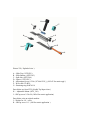
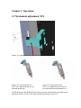
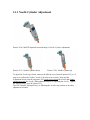
NW Robotics & Technology Inc
MANTS
‘Micro Adjustment Needle Tip Supervision/Needle Cylinder’
Users Manual Ver:1.0
WARNING !
FAILURE OR IMPROPER SELECTION OR IMPROPER USE OF THE
PRODUCT AND/OR SYSTEMS DESCRIBED HEREIN OR RELATED ITEMS
CAN POSSIBLY CAUSE DEATH, PERSONAL INJURY AND PROPERTY
DAMAGE.
This document and other information from NW Robotics & Technology Inc, its
subsidiaries or authorized distributors provide product and/or systems options for further
investigation by user having technical expertise. It is important that you analyze all
aspects of your application, including consequences of any failure and review the
information concerning the product or systems in the current product presentations. Due
to the variety of operating conditions and applications for the products or systems, the
end user, through its own analysis and testing, is solely responsible for making the final
selection of the products and systems and assuring that all performance, safety and
warning requirements of the application are met.
For safety and reducing potential accidents it is strongly recommended to wear safety
glasses at all times when working with described products or systems.
The products described herein, including without limitation, product features,
specifications, design, availability and pricing, are subject to change by NW Robotics &
Technology Inc and its subsidiaries at any time without notice.
Table of contents
Chapter 1: General information
1.1 Features/Application
Chapter 2: Installation
2.1 Initial inspection
2.2 Mechanical installation
Chapter 3: Operation
3.1 Mechanical adjustment NTS
3.1.1 Needle Cylinder adjustment
3.2 Maintenance/checkup
3.3 Problem solver
Chapter 1: General Information
1.1 Features/Application
With the Micro Adjustment for NTS (MANTS) it is now possible to adjust the Needle
Tip Sensor (NTS) in relation to the Needle Cylinder. The NTS sensor only has to be
adjusted once and then follows any Needle Cylinder changes that are made.
In addition to simplifying the NTS setup the MANTS also allows for Micro Adjustment
of the Needle Cylinder to allow for a more precise Needle Height Adjustment and will
also reposition the Needle Cylinder in the same position as it was prior to removing the
complete Needle Cylinder Assembly for easy and quick continuation of production.
Chapter 2: Installation
2.1 Initial inspection
Check to ensure that no shipping damage has occurred.
Included in standard shipment:
1ea complete assembled MANTS ( NTF_5001 ) consisting of:
A - 1ea Slide Top ( NTF1502 )
B - 1ea Slide Bottom ( NTF1503 )
C - 1ea Split-Nut ( NTF1504 )
D - 1ea Spacer ( NTF1505 )
E - 1ea Adjustment Screw 6-32x1 (91746A122-E_) ( M3x25 for metric appl. )
F - 2ea Wave-disk 9714K21
G - 1ea Retaining-ring 98407A116
( if shipped with NTS as shown in this manual the Adjustable Mount (NTF_501) will
also be mounted with its 2 SHCap screws 2-56X1/4 or M2x8 for metric application )
Note: _ is 1 for metric and 0 for inch fasteners
2.2 Mechanical installation
NOTE !
Before installation make sure electrical power and air is disconnected to the
equipment.
Two installations are possible
1 – MANTS without NTS ( Needle Tip Supervision )
2 – MANTS with NTS ( Needle Tip Supervision )
1 – MANTS without NTS ( Needle Tip Supervision )
All that needs to be done is to mount the MANTS assembly between the original Needle
Cylinder L-Bracket and the SHCap mounting screw for the same indicated as K in the
exploded view 221 below.
2 – MANTS with NTS ( Needle Tip Supervision )
Follow all installation instructions in the NTS user manual, with the only exception being
that the Adjustable Mount (NTF_501) is mounted on the MANTS instead of the Cheese
Block. The MANTS is mounted the same way as under point 1 above.
Picture 221 ( Exploded view )
A – Slide Top ( NTF1502 )
B – Slide Bottom ( NTF1503 )
C – Split-Nut ( NTF1504 )
D – Spacer ( NTF1505 )
E – Adjustment Screw 6-32x1 (91746A122-E_) ( M3x25 for metric appl. )
F – Wave-disk 9714K21
G – Retaining-ring 98407A116
Parts below are from NTS ( Needle Tip Supervision )
H – Adjustable Mount (NTF_501)
I – SHCap screw 2-56x1/4 ( M2x8 for metric application )
Parts below exist on original machine
J – Washer for 1/4 “ screw
K – SHCap screw 1/4 “ ( M6 for metric application )
Picture 222 (NTS without MANTS mounted directly on the Cheese Block for visual aid
only, follow NTS manual for NTS installation )
Picture 223 ( MANTS mounted on top of Needle Cylinder L-Bracket )
1 – Needle Cylinder L-Bracket
2 – Bent Tabs on MANTS Slide Top
3 – Original SHCap screw 1/4 “ ( M6 for metric application ) item K picture 222
4 – Original Needle Cylinder mounted on L-Bracket item 1 above
Unscrew SHCap screw, item 3 above holding the Needle Cylinder L-Bracket, and fit the
MANTS assembly on top of the Needle Cylinder L-Bracket, item 1 above. The L-Bracket
is located on the Cheese Block and stays in the same position.
The three (3) bent tabs, indicated with number 2 above may have to be bent slightly to
achieve a snug slip fit over the L-Bracket, item 1 above.
The L-Bracket with it’s complete Needle Cylinder assembly can quickly be removed at
any time by unscrewing the SHCap screw, item 3 above, a few turns to allow the
MANTS assembly to be tilted up, thereby moving the two (2) bottom bent tabs away
from the L-Bracket, and now the L-Bracket with it’s complete Needle Cylinder assembly
can be pulled away from the Cheese Block and when remounted the L-Bracket is held in
the same place as it was before with the three (3) bent tabs.
Picture 224 (NTS completed assembly opposite view for reference only (original VBlock removed for visual aid))
E – Needle Guide
F – Needle
3 – Keyence Optic Fiber Unit (KOFU) ’tip’
It is important when the Keyence Optic Fiber Unit (KOFU, item #3) is installed, that the
Needle Guide (item #E) is moving freely past the tip of the KOFU. By hand move the
Needle and Needle Guide up so the Needle Guide is in front of the KOFU tip. Lightly
push the KOFU in towards the Needle Guide and then back off about 1mm ( 0.04” ) and
tighten the bolt item #C to secure the KOFU. Lightly pull on the fiber optic wire on the
KOFU to ensure that the KOFU is secure and will stay in place. If it is allowed in the
path of the Needle Guide (item #E) it will be damaged.
Chapter 3: Operation
3.1 Mechanical adjustment NTS
Picture 311 (adjustment of Keyence Optic Fiber Unit (KOFU))
Picture 312 (Adjustable Mount
(NTF_501) adjusted all the way up
(towards needle tip))
Picture 313 (Adjustable Mount
(NTF_501) adjusted all the way down
(towards needle hook opening area ))
NOTE! Make sure that the KOFU tip is located as close to the needle as possible but not
interfering with the Needle Guide (item #E) described under picture 224.
The KOFU can now be adjusted by moving Adjustable Mount (NTF_501 item #H picture
221) so that the KOFU beam spot is located on the tip of the needle (item #F) as
illustrated with the dot in picture 311. This should be performed with air connected to the
system so that the needle is guaranteed to be in its lowest down position. Move the
KOFU in the needle tip area marked with X on picture 311.
Picture 312 and 313 show the maximum range of adjustment possible.
The red led display value on the Keyence Fiber Optic Sensor (KFOS) will change from a
low value of about 200 (when above the needle tip or in the needle hook opening area) to
a high value of about 2000 (when sensing the needle or the needle tip). This will aid
when positioning the KOFU so the beam spot is located on the tip of the needle as
illustrated with the dot in picture 311. When done tighten the two SHCap screws
indicated as item #I in picture 221.
Any time a different needle type is installed the KOFU adjustment should be checked and
readjusted as per above so the beam spot is located on the needle tip.
With the KOFU adjusted and pointing onto the needle tip the Keyence Fiber Optic Sensor
(KFOS) can be set. This should be done without air so that the needle can be moved up
and down by hand.
1 - With the needle in its bottom position (the needle tip is sensed and the red led on the
KFOS indicating a value of about 2000) press the set button once on the KFOS.
2 - The green led value will change to two lines.
3 - Move the needle up slightly (the needle hook opening will be sensed) where the red
led value will show its lowest value, about 200, and press the set button again.
4 - The green led value will blink while the switch point is calculated (about 1000) and
then continuously displayed.
5 - To have the NTS function properly it is ESSENTIAL that the original needle down
sensor signal does not turn on before the needle hook opening is detected. Check this by
manually moving the needle up and down while observing the sensor out put lights.
While the KFOS is sensing the lower part of the needle below the needle hook opening
the original needle down sensor cannot be allowed to turn on. If needed move the needle
down sensor further down on the air cylinder so the needle down sensor turns on
somewhere in the area marked with X in drawing 311 where the KFOS is detecting ether
the needle hook opening or the needle tip.
It is a good practice to regularly check the sensor output as indicated in above point 5. At
the start of production, as well as any needle change or adjustment of KOFU position
should be followed with the check under point 5.
3.1.1 Needle Cylinder Adjustment
Picture 3110 ( MANTS depicted in its mid range of Needle Cylinder adjustment)
Picture 3111 ( Needle Cylinder down)
Picture 3112 ( Needle Cylinder up)
To adjust the Needle up or down, unscrew the SHCap screw (item #K picture 221), a 1/4
turn or so to allow the Needle Cylinder L-Bracket to move freely. Now turn the
Adjustment Screw (item #E on picture 221) clock wise to lower the Needle and counter
clockwise to raise the Needle. When adjusted and prior to operating the Needle , tighten
the SHCap screw ( item #K picture 221).
The NTS ( Needle Tip Supervision ) is following the Needles new position so no other
adjustment is needed.
3.2 Maintenance/checkup
1 – The three (3) bent tabs on the MANTS Slide Top (item #2 picture 223) may have to
be readjusted/bent to fit the Needle Cylinder L-Bracket (item #1 picture 223) snuggly.
NEVER force the Adjustment Screw (item #E picture 221) or damage to the MANTS
unit will occur, make sure that SHCap screw ( item #K) is loose during adjustment and
tight before any needle operation.
2 - To have the NTS function properly it is ESSENTIAL that the original needle down
sensor signal does not turn on before the needle hook opening is detected. Check this by
manually moving the needle up and down while observing the sensor out put lights.
While the KFOS is sensing the lower part of the needle below the needle hook opening
the original needle down sensor cannot be allowed to turn on. If needed move the needle
down sensor further down on the air cylinder so the needle down sensor turns on
somewhere in the area marked with X in drawing 311 where the KFOS is detecting ether
the needle hook opening or the needle tip.
Allowed sensor output:
NTS(KFOS)
needle down sensor
detecting lower part of needle(below hook opening) ON
OFF
detecting hook opening
OFF
OFF or ON
detecting tip of needle
ON
ON
It is a good practice to regularly check the sensor output as indicated above. At the start
of production, as well as any needle change or adjustment of the KOFU position should
then be followed with the above check.
3 – Regularly clean the area of the Keyence Optic Fiber Unit (KOFU) tip (Point 3 in
picture 224) to allow for proper detection. Clean the area with compressed air.
3.3 Problem solver
MACHINE HAS STOPPED, NEEDLE NOR CUTTER WILL OPERATE
A – make sure the needle is not broken. If the NTS sensor Keyence Fiber Optic Sensor
(KFOS) is not turned on (red output led) when the needle is in the down position check
that the needle tip is intact. Follow procedure above under point 3.2 Override sensor
output.
B – make sure that when the needle is in the down (bottom) position that both the NTS
sensor Keyence Fiber Optic Sensor (KFOS) and the original needle down sensor are
operating (both sensors output led are on) and that the original controller gets the signal
that the needle is down (original input 301 should be on). This can also be checked by
viewing the display on the Siemens Logo controller 24VDC (SLC24VDC), se picture 231
for reference. The display will show two screens, one shows the input status while the
other shows the output status. Switch between the two displays by pushing ether the Left
or Right arrow indicated with L&R (picture 231 in NTS manual). Input 5 and 6 should be
in a dark square box, indicating the inputs are on (24 volt is received on the inputs). The
output 1 should be in a dark square box, indicating the output is on (sending 24 volt).
C – make sure the Keyence Fiber Optic Sensor (KFOS) has the output selected to ‘Light
on’. Se above point 3.2 Override sensor output.
THE RED LED VALUE IS LOW
A – make sure that the Keyence Optic Fiber Unit (KOFU) ’tip’ is clean, blow out the area
with compressed air.
B – make sure the KOFU tip is positioned as close to the as possible without being in
the way for the needle guide (#E on picture 224).
C – check to make sure that the Keyence Fiber Optic Sensor (KFOS) is set for best
lighting, Super Turbo. Se instruction manual for the sensor under point 8 (User friendly
Functions – Power mode selection)
NOT ENOUGH NEDLE DOWN ADJUSTABILITY
The Adjustable Mount (NTF_501) can be modified when used together with MANTS to
allow for a wider needle travel. File or cut the Adjustable Mount in one of the two
options as indicated above to provide clearance towards a SHCap screw that limits the
needle down adjustment range.