1
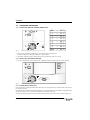
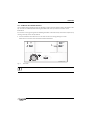
USER INSTRUCTIONS
WALL HUNG RSF GAS FIRED CONDENSING COMBINATION BOILER
GREENSTAR i JUNIOR
6720643356-00.1Wo
FOR CENTRAL HEATING SYSTEMS AND MAINS FED DOMESTIC HOT WATER
6 720 644 863a (2010/10)
UK/IE
PREFACE
PREFACE
PLEASE READ THESE INSTRUCTIONS CAREFULLY
These instructions are applicable to the Worcester, Bosch Group boiler model stated on the front cover
only.
These instructions apply in the UK/IE only and must be followed except for any statutory obligation.
After installation please leave this User instruction Manual, Installation, Commissioning and Servicing
Instructions and completed Benchmark Checklist with the user.
DEDICATED TO HEATING COMFORT
Thank you for purchasing a Greenstar gas-fired condensing combination boiler manufactured by
Worcester, Bosch Group. The company prides itself on manufacturing boilers to the strictest quality
control standards throughout every stage of production.
Worcester, Bosch group has led the field in innovative boiler design and performance for almost 50
years. This heritage means all our products are of exceptional quality and proven reliability.
The Greenstar range in particular is extremely energy efficient, offering you economical running costs
and value for money. It sits in SEDBUK Band A, and is therefore amongst the top energy rated boilers
available.
There is also the reassurance of our no-nonsense 2 years parts and labour guarantee - backed up by
Worcester Total Cover, an optional complete maintenance scheme to keep your boiler operating at
peak condition and efficiency.
2
6 720 644 863a (2010/10)
CONTENTS
CONTENTS
1
1.1
1.2
Symbols and safety precautions . . . . . . . . . . . . . . . 4
Explanation of symbols . . . . . . . . . . . . . . . . . . . . . . . . . . . 4
Safety precautions . . . . . . . . . . . . . . . . . . . . . . . . . . . . . . 5
2
General Information . . . . . . . . . . . . . . . . . . . . . . . . . 6
3
3.1
3.1.1
3.1.2
3.1.3
3.1.4
3.1.5
Controls . . . . . . . . . . . . . . . . . . . . . . . . . . . . . . . . . . . . 7
Operating the boiler . . . . . . . . . . . . . . . . . . . . . . . . . . . . . 8
Setting the central heating temperature . . . . . . . . . . . . . 8
Switch off the central heating . . . . . . . . . . . . . . . . . . . . . 8
Boiler frost protection . . . . . . . . . . . . . . . . . . . . . . . . . . . . 8
Domestic hot water pre-heat . . . . . . . . . . . . . . . . . . . . . . 9
Boiler reset . . . . . . . . . . . . . . . . . . . . . . . . . . . . . . . . . . . 10
4
4.1
4.2
4.3
System Pressure . . . . . . . . . . . . . . . . . . . . . . . . . . .
Sealed heating systems . . . . . . . . . . . . . . . . . . . . . . . .
Using the optional integral filling link . . . . . . . . . . . . . .
External filling loop . . . . . . . . . . . . . . . . . . . . . . . . . . . .
5
Service Clearances . . . . . . . . . . . . . . . . . . . . . . . . . 14
6
Maintaining your Boiler . . . . . . . . . . . . . . . . . . . . . 15
7
Fault Finding . . . . . . . . . . . . . . . . . . . . . . . . . . . . . . . 16
8
Fault or Breakdown . . . . . . . . . . . . . . . . . . . . . . . . . 18
9
TIPS ON ENERGY SAVING . . . . . . . . . . . . . . . . . . . 19
10
Environment / disposal . . . . . . . . . . . . . . . . . . . . . 21
11
Your Guarantee . . . . . . . . . . . . . . . . . . . . . . . . . . . . 22
12
Glossary . . . . . . . . . . . . . . . . . . . . . . . . . . . . . . . . . . . 23
6 720 644 863a (2010/10)
11
11
12
13
3
SYMBOLS AND SAFETY PRECAUTIONS
1
SYMBOLS AND SAFETY PRECAUTIONS
1.1
EXPLANATION OF SYMBOLS
WARNING SYMBOLS
Safety instructions in this document are framed and identified by a
warning triangle which is printed on a grey background.
Electrical hazards are identified by a lightning symbol surrounded by a warning triangle.
Signal words indicate the seriousness of the hazard in terms of the consequences of not following the
safety instructions.
•
NOTICE indicates possible damage to property or equipment, but where there is no risk of personal
injury.
•
CAUTION indicates possible personal injury.
•
WARNING indicates possible severe personal injury.
•
DANGER indicates possible risk to life.
IMPORTANT INFORMATION
Notes contain important information in cases where there is no risk of
personal injury or material losses and are identified by the symbol shown on the left.
They are bordered by horizontal lines above and below the text.
ADDITIONAL SYMBOLS
Symbol
Meaning
B
a step in an action sequence
Æ
a reference to a related part in the document or to other related documents
•
a list entry
–
Tab. 1
4
a list entry (second level)
Symbols
6 720 644 863a (2010/10)
SYMBOLS AND SAFETY PRECAUTIONS
1.2
SAFETY PRECAUTIONS
IF YOU SMELL GAS!
B Call the National Gas Emergency Service on: 0800 111 999
B Extinguish any naked flames
B Do not smoke or strike matches
B Do not turn electrical switches on or off
B Open doors and windows
B Keep people away from the affected area
B Turn off the gas control valve at the meter
BOILER OPERATION:
This boiler must only be operated by a responsible adult who has been instructed in, understands and
is aware of the boiler's operating conditions and effects.
COMBUSTIBLE AND CORROSIVE MATERIALS:
Chemically aggressive substances can corrode the boiler and invalidate any warranty.
B Do not store or use any combustible materials (paper, thinners, paints etc.) inside or within the
vicinity of the boiler.
FITTINGS AND MODIFICATIONS:
Only a competent engineer in accordance with the Gas Safety (Installation and Use) Regulations can
remove the outer case and carry out any work.
B Do not remove the outer casing.
Any misuse or unauthorised modifications to the boiler, flue or associated components and system will
invalidate the warranty.
B Do not modify the boiler or flue system in any way.
Worcester, Bosch Group accepts no liability arising from any such actions. This does not affect your
statutory rights.
6 720 644 863a (2010/10)
5
GENERAL INFORMATION
2
GENERAL INFORMATION
SERVICING
Ensure that the service engineer completes the Service Record in the Benchmark
Checklist after each service. The Benchmark Checklist and service interval record can be
found at the rear of the Installation, Commissioning and Servicing Instructions.
B The boiler must be serviced regularly by a competent, qualified person, such as a Worcester service
engineer or other Gas Safe registered engineer.
B Always use original spares, to help maintain the economy, safety and reliability of the boiler and
have the Service Record completed in the Benchmark Checklist.
The completed Benchmark Checklist will be required in the event of any warranty work and may be
required by the local Building Control Inspector.
BENCHMARK STANDARD
The Benchmark initiative is a code of practice to encourage the correct
installation, commissioning and servicing of domestic central heating
boilers and system equipment.
A “log book” is dispatched with every boiler. This is a vital document
that needs to be completed by the installer at the time of installation.
It confirms that the boiler has been installed and commissioned according to the manufacturers
instructions.
The log book provides space for the recording of regular servicing of the boiler/system and this can
become a valuable document when, for example, the householder wishes to sell the property. The log
book will show a potential purchaser that the heating system has received regular professional
attention during its lifetime.
The Benchmark initiative aims to:
•
Raise standards among professional installers
•
Build and maintain high safety standards in the industry
•
Improve customer satisfaction levels
•
Make a contribution to the nation‘s commitment to “Climate Change”
6
6 720 644 863a (2010/10)
CONTROLS
3
CONTROLS
B To gain access to the boiler controls push the top centre of the flap and release.
2
3
4
5
6
7
8
6720644863-06.1Wo
1
Fig. 1
Control panel fascia
Boiler
Controls
1
Central heating temperature control
5
Power ON and fault indicator (Blue)
2
Burner indicator (Green)
6
ECO button
3
Service button
7
Reset button
4
Cover or optional Programmer
8
System pressure gauge
6 720 644 863a (2010/10)
7
CONTROLS
3.1
OPERATING THE BOILER
3.1.1 SETTING THE CENTRAL HEATING TEMPERATURE
Min
--- 40 °C
1
--- 47 °C
2
--- 53 °C
3
--- 61 °C
4
--- 68 °C
5
--- 74 °C
6
6
--- 80 °C
max
Max
--- 82 °C
2.
3
4
5
2
1.
Fig. 2
Central heating temperature control
1. Turn the central heating temperature control knob to the desired level.
Temperatures given in the figure below are approximate.
2. The Burner indicator (green) will illuminate to show that the boiler is running.
3.1.2 SWITCH OFF THE CENTRAL HEATING
1. Turn the temperature control knob to the snowflake symbol to switch off the central heating.
reset
eco
3
4
2
1.
1
5
6
max
Fig. 3
Switch off central heating
3.1.3 BOILER FROST PROTECTION
If the temperature within the boiler falls below 8°C the pump will run to circulate water and prevent
the system freezing.
If the temperature within the boiler falls below 5°C the boiler will fire periodically, bringing the boiler
temperature up to 12°C to avoid the possibility of the system freezing.
This process will be repeated until such time that the boiler temperature does not drop below 5°C.
8
6 720 644 863a (2010/10)
CONTROLS
3.1.4 DOMESTIC HOT WATER PRE-HEAT
The hot water heat exchanger is kept "pre-heated" to reduce the time taken to deliver hot water at the
tap. Pre-heat is enabled by default during the initial boiler start up and the Eco button is not
illuminated.
Eco mode is an energy saving function allowing hot water to be heated only as and when required, by
running a hot tap, this is OFF by default.
1. Press and hold the Eco button for four seconds to enter the energy saving Eco mode.
When the ECO mode is active the button will be illuminated.
reset
1.
3
2
1
eco
4
5
6
max
6720644863-04.1Wo
Fig. 4
Eco mode
The domestic hot water is factory set to approximately 55°C.
6 720 644 863a (2010/10)
9
CONTROLS
3.1.5 BOILER RESET
In the event of a fault, the reset button will flash once per second and the blue mains indicator light
will flash.
1. To reset the boiler press the reset button for approximately five seconds.
When the boiler resets the reset button will no longer be illuminated.
2. The mains indicator will no longer be flashing.
1.
reset
eco
2.
3
2
1
4
5
6
max
6720644863-03.1Wo
Fig. 5
Reset button and mains light
If the fault remains and cannot be cleared by pressing the reset button, contact
Worcester, Bosch Group for assistance.
10
6 720 644 863a (2010/10)
SYSTEM PRESSURE
4
SYSTEM PRESSURE
4.1
SEALED HEATING SYSTEMS
This boiler is fitted to a sealed heating system which is pre-pressurised. Your installer will advise you
of the minimum and maximum pressure indicated on the pressure gauge.
B Check regularly that the pressure is maintained.
1.5 bar
Max
2
1
3
Min
0
Fig. 6
bar
4
6720643356-11.1Wo
1 bar
A
Optimum pressure when cold (area A)
B Contact your installer or maintenance engineer if a permanent significant decrease or increase in
pressure is indicated on the pressure gauge.
The filling method will be one of two types:
•
Optional integral filling kit, which is supplied with a white T shaped filling key.
•
An external filling loop, fitted valves and flexible hose.
6 720 644 863a (2010/10)
11
SYSTEM PRESSURE
4.2
USING THE OPTIONAL INTEGRAL FILLING KIT
Locate filling key and follow instructions for re-pressurising.
1. Push the filling key firmly into the body of the filling link, ensuring the arrow on the key shaft lines
up with the open padlock symbol.
2. Turn the filling key to the right, to the stop, so the arrow now lines up with the closed padlock
symbol. This bridges the gap between the two sections of the filling loop.
3. Turn the white knob, to the left of the key, anticlockwise. This will allow water to fill the system.
1.
2.
3.
4.
6720643356-10.2Wo
5.
Fig. 7
Inserting the filling key
4. When the pressure, shown on the pressure gauge, reaches between the 1 and 1.5 bar marks, turn
the white knob clockwise to close the valve.
5. Turn the filling key to the left, to the stop, so that the arrow lines up with open padlock symbol and
pull the key the key straight down to remove.
12
6 720 644 863a (2010/10)
SYSTEM PRESSURE
4.3
EXTERNAL FILLING LOOP
Once the external filling loop has been located, follow instructions for re-pressurising.
1. Un-screw blanking cap.
2. Attach hose and screw on hand tight to valve.
3. Turn the handle/screwdriver slot point 90° to open the valves.
4. The handle/screwdriver slot point will be in-line with the valves
4.
1.
2.
4.
3.
3.
6720643356-12.1Wo
Fig. 8
External filling loop
5. When the pressure reaches between the 1 and 1.5 bar marks, turn the handle/screwdriver slot point
back to close it.
6. Remove hose and replace blanking cap.
6 720 644 863a (2010/10)
13
SERVICE CLEARANCES
5
SERVICE CLEARANCES
Your installer will have provided adequate space around the boiler for safety and servicing access.
CAUTION: Restricted space.
The boiler may overheat.
B Do not restrict this space with the addition of cupboards, shelves etc. next to the
boiler.
+ 30 mm
above elbow
5 mm
600 mm
200 mm
Fig. 9
14
6720643356-01.1Wo
5 mm
Service clearances
6 720 644 863a (2010/10)
MAINTAINING YOUR BOILER
6
MAINTAINING YOUR BOILER
Your new gas-fired boiler represents a long term investment in a reliable, high quality product.
In order to realise its maximum working life, and to ensure it continues to operate at peak efficiency
and performance, it is essential that your boiler receives regular servicing and maintenance checks
from a competent person beyond the initial 2 year guarantee period.
If you would like to know more about a Worcester, Bosch Group service contract, please tick the
appropriate box on your warranty registration card.
If your gas-fired boiler should fail to operate correctly or requires servicing please contact Worcester,
Bosch Group Appointments Team (see rear cover for details).
Details of the boiler including the Gas Council number can be found under the controls covers flap on
the boiler.
The Gas Council number is also listed on the front cover of your Installation, Commissioning and
Servicing Instructions.
6 720 644 863a (2010/10)
15
FAULT FINDING
7
FAULT FINDING
If a boiler fault occurs, please read the following page thoroughly before contacting Worcester, Bosch
Group.
Problem
Cause
Remedy
Desired room temperature is
not reached
Thermostatic radiator valve(s)
set too low
B Increase thermostatic
radiator valve setting(s)
Temperature control for
central heating flow on boiler
set too low
B Increase central heating
flow temperature control
setting
Air trapped in heating system
B Bleed radiators and
recharge heating system
Radiators are too hot
B Turn down thermostatic
radiator valves/room
thermostat
Desired room temperature
exceeded by large amount
B Reduce central heating
temperature by turning
down the Central Heating
control on boiler
Heating stays on for too long
Clock is incorrectly set
B Check setting and adjust
No ON/OFF mains indicator
Momentary power failure
B Switch off boiler at master
switch, wait a few seconds
then switch on again
Hot water temperature too
low
Water flow at tap too high
B Reduce flow rate at tap
Hot water temperature too
high
Water flow at tap too low
B Increase flow rate at tap
Tab. 2
16
6 720 644 863a (2010/10)
FAULT FINDING
EXTREME COLD WEATHER
In instances where the condensate pipe work is run external or in an unheated area, such as a garage,
it can be at risk of freezing, even if insulated.
A frozen condensate pipe will cause the boiler to shut down.
WARNING: Falling hazard!
Failure to follow this guidance can result in personal injury.
B Only attempt to thaw a condense pipe that is at ground level, which is easily
accessible.
B Never attempt to thaw a condense pipe which is at height.
CAUTION: Pipe damage
B DO NOT use boiling water to thaw the condensate pipe!
If the condensate pipe has frozen:
B Locate the blockage.
It is likely that the pipe is frozen at the most exposed point external to the building or where there
is some obstruction to flow. This could be the open end of the pipe, at a bend or elbow, or where
is a dip in the pipe in which condensate can collect. The location of the blockage should be
identified as closely as possible before taking further action.
B Thaw the frozen pipe.
The pipe can be thawed by applying a hot water bottle, a microwaveable heating pack (the sort used
for muscular aches and pains) or a cloth soaked in hot water to the exterior of the pipe, close to
the point of blockage. Hot water can also be poured onto the pipe from a watering can or similar
container.
B Once the pipe has been thawed the boiler must be reset, press the reset button for five seconds
and wait two to three minutes for the boiler to restart.
B If the boiler does not restart, contact Worcester’s Technical Support Team (0844 892 3366) for
assistance.
B Contact your installer in order to find a permanent solution to the problem.
6 720 644 863a (2010/10)
17
FAULT OR BREAKDOWN
8
FAULT OR BREAKDOWN
This boiler is supported in the UK and Eire by Worcester, Bosch Group.
Specialist Service Engineers are available to attend a breakdown occurring on this boiler.
Invoices for attendance and repair work carried out on this boiler by any third party will
not be accepted.
•
No charge will be made for parts and/or labour providing:
A boiler fault is found and the appliance has been installed within the past 24 months. Reasonable
evidence of this must be supplied on request. i.e. the Benchmark Checklist.
•
A call-out charge will be made where:
– The boiler has been installed for over 24 months.
– Evidence cannot be provided that the first year service inspection has been carried out (i.e. an
entry in the Benchmark Checklist).
– Our Field Service Engineer finds no fault with the boiler.
– The cause of breakdown is misuse or with other parts of your plumbing/heating system, or with
equipment not supplied by Worcester, Bosch Group.
TECHNICAL SUPPORT
No boiler fault is found on over 30% of all service calls.
In the case of a suspected fault, refer to the fault finding section of this guide.
In the event of a boiler fault or breakdown please contact Worcester, Bosch Group appointments team
on 0844 892 3000.
Your advisor will arrange for an engineer to call with the minimum of delay; under normal
circumstances this will be from 1 - 3 working days (excluding weekends) for priority breakdown
situations (no hot water and/or heating).
18
6 720 644 863a (2010/10)
TIPS ON ENERGY SAVING
9
TIPS ON ENERGY SAVING
HEATING ECONOMICALLY
The boiler provides a high level of comfort whilst keeping gas consumption and the environment
effects as low as possible.
The gas supply to the burner is controlled according to the level of demand for heat. The boiler
operates with a low flame if the demand for heat reduces. The technical term for this process is
modulating control.
Modulating control reduces temperature fluctuations and provides an even distribution of heat
throughout the home. This means that the boiler may stay on for relatively long periods of time but will
use less gas than a boiler that continually switches on and off.
CENTRAL HEATING SYSTEMS WITH ROOM THERMOSTAT/THERMOSTATIC RADIATOR VALVES
With modern heating systems set around a 20 °C heat loss, the optimum setting for a condensing boiler
will be approximately between one and two on the central heating temperature control. The system
must be balanced correctly and the radiators may need upgrading. This allows the boiler to condense
as much as possible for the central heating system.
The temperature of each room can be set individually (except primary room with the room thermostat)
using the thermostatic radiator valves.
ROOM THERMOSTATS
Reducing the setting of the room thermostat by 1 °C can reduce fuel consumption by up to 10%.
NEW CONTROL SYSTEMS
Upgrade your heating control system if necessary with the latest equipment available. The minimum
level of control is a programmer, interlocking room thermostat and thermostatic radiator valves.
ROOF INSULATION
Around 30% of the heat loss from a property is through the roof. Replace any old insulation with new
insulation, preferably of around 200 mm thickness or more.
WINDOW FRAMES
Single glazed windows, particularly those with steel frames, can lose a great deal of heat.
Consideration should be given to replacement with PVCu or wooden framed double glazed units.
RADIATORS
If a radiator is sited underneath a window, its performance will be affected if the curtains are allowed
to drape over the radiator. Shelves fitted above or in front of the radiator should also be avoided.
It is advisable to manually adjust all thermostatic radiator valves every 2 - 3 months to prevent them
sticking. Ensure radiator valves are correctly set and not damaged.
6 720 644 863a (2010/10)
19
TIPS ON ENERGY SAVING
DRAUGHTS
Try to ensure that draughts around doors, windows, letterboxes and keyholes etc. are
reduced by using a suitable draught excluder.
WARNING: AIR VENTS
B Do not block or seal any air vents that are installed to ensure that the central heating
boiler operates safely.
CURTAINS
Lined curtains, or heavier full length curtains can provide excellent insulation. However,
always ensure that the curtains do not drape over radiators.
20
6 720 644 863a (2010/10)
ENVIRONMENT / DISPOSAL
10 ENVIRONMENT / DISPOSAL
Environmental protection is a fundamental corporate strategy of the Bosch Group.
The quality of our products, their economy and environmental safety are all of equal importance to us
and all environmental protection legislation and regulations are strictly observed.
We use the best possible technology and materials for protecting the environment taking account of
economic considerations.
PACKAGING
We participate in the recycling programmes of the countries in which our products are sold to ensure
optimum recycling.
All of our packaging materials are environmentally compatible and can be recycled.
USED APPLIANCES
B All Greenstar gas boilers are 100% recycleable.
The various assemblies can be easily dismantled and synthetic materials are marked
accordingly. Assemblies can therefore be sorted by composition and passed on for
recycling.
6 720 644 863a (2010/10)
21
YOUR GUARANTEE
11 YOUR GUARANTEE
This boiler is guaranteed against faulty materials or workmanship for a period of 2 years from the date
of installation subject to the following terms and conditions.
•
During the period of this guarantee any components of the boiler which are proven to be faulty or
defective in manufacture will be exchanged or repaired free of charge by Bosch Thermotechnology
Ltd.
•
The householder may be asked to prove the date of installation, that the boiler was correctly
commissioned and, where appropriate, the first year‘s service has been carried out to the
satisfaction of Bosch Thermotechnology Ltd., when requested. These should be part of the
Benchmark Checklist.
•
The boiler has been used only for the normal domestic purposes for which it was designed.
This guarantee does not affect your statutory rights.
GUARANTEE REGISTRATION
Returning the card will register you as the owner of your new gas boiler and will assist us in maintaining
an effective and efficient customer service by establishing a reference and permanent record for your
boiler.
FOR YOUR OWN RECORD:
Please ensure that the Benchmark Checklist has been completed by your installer or service engineer.
Model
Serial No.1)
Type/size
Date of installation
Name of Installer
Telephone number of Installer
Tab. 3
1) See identity label on control panel/flap or Benchmark Checklist.
22
6 720 644 863a (2010/10)
GLOSSARY
12 GLOSSARY
Central heating systems
All radiators must be heated at an even rate. If the top of a radiator is at a lower temperature than the
bottom then it should be vented by releasing air through the venting screw at the top of the radiator.
Ask your installer to show you how this is done.
This boiler is fitted to a sealed system. Should water leaks be found or if excessive venting is required,
then a service engineer must be contacted to inspect the installation and rectify any fault.
Only additives that are compatible with aluminium may be used in the system. Any incompatible
additive used will invalidate the guarantee.
Pluming and Condensate drain
This is a condensing boiler and the flue terminal will, at times give out a plume of water vapour. This
is quite normal.
The boiler produces condensate which is discharged regularly by a syphon within the boiler via a
plastic pipe to a drain. This pipe must not be blocked or altered in any way.
Room thermostat / programmer
A room thermostat / programmer must be fitted to control the central heating. This controls the times
and temperatures of the central heating, preventing the boiler from firing unnecessarily. Refer to the
instructions supplied with the thermostat and programmer for further information.
Thermostatic radiator valves
Thermostatic radiator valves must be fitted in sleeping accommodation. It is recommended that this
type of valve is fitted to all but one of the radiators. The remaining radiator, where the room thermostat
is located, must be uncontrolled and left open.
Pump over run function
After the boiler has finished a demand for central heating or hot water, the pump continues to run for
three minutes to dissipate the heat from within the boiler.
Pump anti-seizure
If there has been no heating demand for 24 hours the boiler will run the system pump for a few seconds
to reduce the possibility of pump seizure during long periods of inactivity.
SEDBUK
Seasonal Efficiency of Domestic Boilers in the UK.
6 720 644 863a (2010/10)
23
WORCESTER, BOSCH GROUP:
TECHNICAL SUPPORT: 0844 892 3366
APPOINTMENTS:
WEBSITE:
Worcester, Bosch Group
Cotswold Way, Warndon, Worcester WR4 9SW.
Tel. 0844 892 9900
Worcester, Bosch Group is a brand name of
Bosch Thermotechnology Ltd.
6 720 644 863a (2010/10)
0844 892 3000
worcester-bosch.co.uk