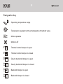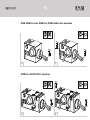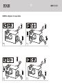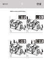
1
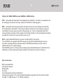
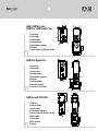
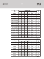
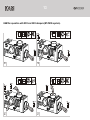
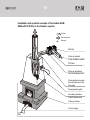
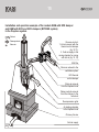
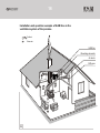
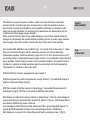
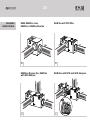
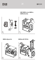
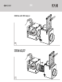
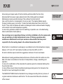
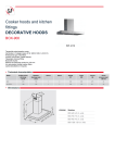
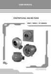
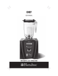
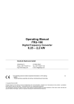
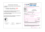
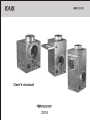
ÊÀÌ
User's manual
2014
2
CONTENT
ÊÀÌ
1. Function
ð. 3
2. Delivery set
ð. 3
3. Basic technical characteristics
ð. 3
4. Safety requirements
ð. 17
5. Fan structure
ð. 17
6. Mounting and setting-up procedure
ð. 18
7. Fan connection to power supply network
ð. 19
8. Mounting modifications
ð. 20
9. Fan wiring diagrams
ð. 22
10. Servicing and maintenance
ð. 25
11. Storage rules
ð. 25
12. Manufacturer's warranty
ð. 25
13. Failures and troubleshooting methods
ð. 26
14. Acceptance certificate
ð. 27
15. Warranty card
ð. 27
ÊÀÌ
3
Electric centrifugal fan VENTS KAM in metal casing with impeller diameter range
from 146 up to 158 mm with forward curved blades, hereafter referred to as fan,
is a part of fireplace heating system and designed for transferring of fresh air with the
temperature +150°Ñ from the fireplace hood into various premises through the ductwork
to improve chimney efficiency jointly with ventilation system.
FUNCTION
The fan is suitable for vertical and horizontal mounting and used both for supply ventilation
to move warm air from the heating source and for exhaust ventilation to remove warm air
excess during ventilation in premises.
The fan is easy to use and designed for continuous operation with permanent power
supply for the operating temperature ranging from +20°Ñ to +150°Ñ.
The fan is equipped with a temperature regulator to set the required temperature value
adjustable between 0°Ñ and +90°Ñ.
Protection rating from access to dangerous parts and water penetration is IPX2.
The delivery set includes:
fan - 1 pc;
options (in compliance with the purchase order);
user's manual;
packing box
The fan designations, options, operating logic and connecting dimensions are shown
in tables 1, 2 and fig. 1-24.
The fan design is regularly being improved and some models can slightly differ from
those ones described in this manual.
DELIVERY
SET
BASIC
TECHNICAL
CHARACTERISTICS
4
ÊÀÌ
x x x x
Temperature regulator:
T1 - no built-in temperature regulator
Fan modifications:
Eco - low power demand
EcoDuo - low power demand and switch
Eco Bypass - built-in mixing chamber with backdraft damper
Eco max - high-powered motor
Intake and exhaust branch pipe diameters:
125; 140;150; 160; 200
Fan designation:
KAM - centrifugal fan in metal casing
Designation key:
VENTS KAM 125 - centrifugal fan in metal casing for connection to ø 125 mm
round air ducts.
VENTS KAM 150 Eco max - centrifugal fan in metal casing for connection to ø 150 mm
round air duct equipped with high-powered motor.
VENTS KAM 140 EcoDuo - centrifugal fan with low power demand, built-in motor
speed switch in metal casing for connection to ø 140 mm round air duct.
VENTS KAM 150 Eco T1 - centrifugal fan with low power demand in metal casing
for connection to ø 150 mm round air ducts without built-in temperature regulator.
VENTS KAM 160 Eco Bypass - centrifugal fan with low power demand in metal casing
with built-in mixing chamber and backdraft damper for connection to ø 160 mm
round air ducts.
ÊÀÌ
5
Options for KAM, KAM Eco max, KAM Eco, KAM EcoDuo:
FFK - removable G3 metal filter for transported air purification. The filter is connected to the
fan casing by lock-latches for easy removal of the filter for cleaning (fig.3).
KFK - removable metal mixing chamber with built-in thermal control damper and G3 filter
for transported air purification. The mixing chamber is fixed to the fan casing by means of
lock-latches to ensure easy removal for cleaning (fig. 4). The fan configuration with KFK
mixing chamber provides cold air supply to the mixing chamber as the operating temperature
exceeds 90°Ñ and hot air removal as the motor is off.
GFK – gravity backdraft damper to prevent air back draft in the system.
The ventilation unit equipped with KFK mixing set and GFK backdraft damper ensures
the motor overtemperature protection based on BYPASS actuation when the motor is
switched off due to no power supply.
The BYPASS system in chimney fans provides gravity backdraft damper shutoff and hot air
distribution to other premises through ventilation ducts when the motor is off (fig. 5).
Fan accessories:
MFK removable filter
GFK gravity damper;
Metal grilles;
Air ducts;
Connecting and mounting components;
Temperature regulator. The recommended temperature regulators are the remote models
for KAM T1, KAM EcoDuo T1 of VENTS production.
ÊÀÌ
6
D
H
6
7
D
B
1-fan casing;
2-inlet flange;
3-terminal box;
4-exhaust flange;
5-temperature regulator;
6-impeller;
7-speed switch (for EcoDuo model).
h
KAM, KAM Eco max,
KAM Eco, KAM EcoDuo fan
1
C
A
2
7
h
KAM Eco Bypass fan
8
4
5
D
D
D
B
9
C
A
7
6
h
2
H
6
1-fan casing;
2-inlet flange;
3-terminal box;
4-exhaust flange;
5-temperature regulator;
6-impeller;
7-mixing chamber;
8-backdraft damper;
9-reverse air duct flange
3
9
2
4
D
5
D
B
1-KAM fan;
2-exhaust flange;
3-terminal box;
4-temperature regulator;
5-speed switch (for EcoDuo model);
6-filter casing;
7-inlet flange;
8-filter element;
9-latches.
H
8
KAM fan with FFK filter
C
A
ÊÀÌ
7
7
h
6
10
H
8
D
KAM fan with KFK damper
11
1-KAM fan;
9
2-exhaust flange;
3-terminal box;
4-temperature regulator;
5-speed switch (for EcoDuo model)
6-mixing chamber;
7-intake flange;
8-thermal control damper;
9-reverse air duct flange;
10-filter element;
11-latches.
2
4
5
D
CA
D
4
D
h
H
11
13
2
4
5
CA
D
1-KAM fan;
9
2-exhaust flange;
12
3-terminal box;
4-temperature regulator;
5-speed switch (for EcoDuo model).
6-mixing chamber;
7-intake flange;
8-thermal control damper;
9-reverse air duct flange;
10-filter element;
11-latches.
12-gravity backdraft damper;
13-fixing screw.
5
10
8
D
KAM fan with KFK and
GFK dampers
7
6
D
D
ÊÀÌ
8
Dimensions [mm]
C
D
Fan
type
À
B
ÊÀÌ 125
260
245
210
ÊÀÌ 140
300
285
250
ÊÀÌ 150
300
285
ÊÀÌ 160
300
ÊÀÌ 125 Eco Bypass
Í
h
Weight
[kg]
125
350
50
4,5
140
350
50
5,7
250
150
350
50
5,7
285
250
160
350
50
5,7
310
245
210
125
462
50
7,8
ÊÀÌ 140 Eco Bypass
350
285
250
140
522
50
9,8
ÊÀÌ 150 Eco Bypass
350
285
250
150
522
50
9,8
ÊÀÌ 160 Eco Bypass
350
285
250
160
522
50
9,8
7,3
ÊÀÌ 150 Eco max
300
285
250
150
320
50
ÊÀÌ 125 Eco / EcoDuo
260
245
210
125
320
50
5,6
ÊÀÌ 140 Eco / EcoDuo
300
285
250
140
320
50
6,8
ÊÀÌ 150 Eco / EcoDuo
300
285
250
150
320
50
6,8
ÊÀÌ 160 Eco / EcoDuo
300
285
250
160
320
50
6,8
ÊÀÌ 200 Eco
335
350
285
200
350
50
7,8
Table 1
Dimensions [mm]
C
D
Fan
accessory type
À
B
FFK 125
260
245
210
FFK 140
300
285
250
FFK 150
300
285
250
FFK 160
300
285
250
Weight
[kg]
Í
h
125
180
50
2,2
140
190
50
3,0
150
190
50
3,0
190
50
3,0
3,8
160
KFK 125
260
245
210
125
260
50
KFK 140
300
285
250
140
300
50
4,0
KFK 150
300
285
250
150
300
50
4,0
KFK 160
300
285
250
160
300
50
4,0
Table 2
ÊÀÌ
9
Designation key
t
90
45
Operating temperature range
î
45
~
~
~
Temperature regulator with set temperature threshold value.
Motor operates
Motor is off
t
Thermal control damper is open
t
Thermal control damper is closed
~
~
~
~
~
~
~
~
~
~
~
~
Gravity backdraft damper is open
Gravity backdraft damper is closed
Backdraft damper is open
Backdraft damper is closed
ÊÀÌ
10
KAM, KAM Eco max, KAM Eco, KAM EcoDuo fans operation
î
~
~
~
î
45
45
t
90
45
t
t
45
90
0
45
6
7
KAM Fan with FFK filter operation
t
90
î
45
t
45
t
45
0
8
~
~
~
î
45
90
45
9
ÊÀÌ
11
KAM Eco Bypass fan operation
t
î
45
90
12
î
45
45
t
t
~
~
~
90
45
90
45
t
t
90
90
45
45
10
11
t
î
45
t
~
~
~
25
0
î
45
t
150
90
120
70
t
150
t
90
12
150
90
13
ÊÀÌ
12
KAM fan operation with KFK damper
t
t
î
45
t
90
45
t
~
~
~
î
45
t
45
14
15
t
t
120
70
25
0
t
î
45
t
~
~
~
t
150
90
t
î
45
t
150
90
16
90
45
0
150
90
17
ÊÀÌ
13
KAM fan operation with KFK and GFK dampers (BY-PASS system).
~
~
~
t
î
t
45
~
~
~
90
45
t
t
~
~
~
î
45
t
45
0
18
t
19
t
120
25
~
~
~
t
~
~
~
~
~
~
î
45
t
0
70
t
î
45
150
90
t
t
150
90
20
90
45
150
90
21
ÊÀÌ
14
Installation and operation example of fan models KAM,
KAM with FFK filter in the fireplace system.
Cold air
Flame products
Warm air
KAM fan
Warm air exhaust
to the ventilation system
FFK filter
Warm air withdrawal
from the fireplace hood
Flame products removal
from the chimney to the
fume duct
Decompression grille
Air heating chamber
in the fireplace hood
Chimney furnace
Cold air supply
22
ÊÀÌ
15
Installation and operation example of fan models KAM with KFK damper
and KAM with KFK and GFK dampers (BYPASS system)
in the fireplace system.
Cold air
Flame products
Warm air
Reverse air duct:
1. Hot air removal with the
thermal control damper
(fig. 13,17);
2. Cold air supply to the
mixing chamber for mixing
with hot air (fig. 12, 16)
KAM fan
Warm air exhaust to the
ventilation system
KFK thermal
control damper
Warm air removal
from the fireplace hood
Flame products removal
from the chimney to the
fume duct
Decompression grille
Air heating chamber
in the fireplace hood
Chimney furnace
Cold air supply
23
16
ÊÀÌ
Installation and operation example of KAM fans in the
ventilation system of the premise.
Cold air
Warm air
KAM fan
Mounting elements
Air ducts
Diffusers
24
ÊÀÌ
17
Take actions to prevent ingress of smoke, carbon monoxide and other combustion
products into the room through open chimney flues or other fire-protection devices.
Fan shall be mounted and installed by a duly qualified electrician im compliance with
acting norms and standards. Fan servicing and maintenance are allowed after the fan
is disconnected from power supply network.
Make sure that the fan is free of any visible damages or any foreign objects inside the
casing that may damage the impeller before connecting the fan to power supply network.
Power supply cable must not be in contact with any hot fan and air duct surfaces.
Fan models KAM, KAM Eco max, KAM Eco (fig. 1,2) consist of the metal casing 1, intake
flange 2 and exhaust flange 4 with the diameters equals to the air duct diameters,
temperature regulator 5 with the operating range from 0°C to 90°C and terminal box 3 for
connecting the fan to single-phase power supply network. Fan modification without terminal
box is possible. The fan casing consists of two insulated chambers. The electric motor is
installed in a separate chamber protected against overheating from the transported air.
The impeller 6 is installed on the motor shaft.
KAM EcoDUO fan model is equipped with speed switch 7.
KAM Eco Bypass fan model incorporates the mixing chamber 7, the backdraft damper 8
and the reverse duct flange 9 (fig.2).
FFK filter consists of the filter casing 6, intake flange 7, removable filtering element 8
and latches 9 (fig.3). FFK filter is connected to KAM fan with latches.
KFK damper consists of the mixing chamber 6, intake flange 7, thermal control damper 8,
reverse duct flange 9, removable filter element 10, latches 11 (fig. 4). KFK damper filter is
connected to KAM fan by means of latches.
Joint installation of KFK thermal control damper and GFK gravity backdraft damper 12
provide BYPASS operation for extra motor overheating protection of KAM fans.
GFK damper is mounted on the intake flange and fixed by retaining screw 13 (fig.5).
SAFETY
REQUIREMENT
FAN
STRUCTURE
18
!
WARNING
MOUNTING AND
SETTING-UP
PROCEDURE
!
WARNING
ÊÀÌ
Use only heat-resistant metal air ducts and grilles while mounting the fan
in the ventilation system.
Do not use the fan in the explosive or fire hazardous environment.
After unpacking the fan make sure of no damages in the power supply line and no
cuts and crack in the cable insulation, check the fan casing for no hollows and other
distortions. The impeller shall have smooth rotation and be not in contact with the intake
flange and the casing.
Observe general and special safety precautions during the fan setting-up and operation.
The fan shall have reliable grounding. The circuit breaker shall be installed in such a
way as to provide easy access and control of the fan start-up procedure.
The fan shall be installed vertically or horizontally on a level surface depending on the
fan model. The fan mounting options are shown in fig. 25-32.
While mounting provide free air access to the fan for its cooling. Install the fan on the
mineral wool layer on the rigid fire-resisting plate (gypsum board 0.5 x 0.5 m) to reduce
vibration.
Keep the minimum distance from the fan to the heating source 1.5 m and the minimum
distance from the fan casing to the neighbouring objects 0.5 m. Install the required
amount of the decompression grilles in the fireplace hood, intake and air distribution
ducts and fix them with the clamps.
The air ducts shall have thermal insulation with mineral wool. The intake air duct
shall be placed 10-20 cm below the decompression grilles level.
Air flow direction in the system shall match the direction of the arrowhead on the fan
casing. For KAM B fan models adjust the gravity backdraft damper position in
compliance with the arrowhead direction preserving the horizontal damper position.
The damper protects the system and the fan from overheating as the chimney is
operating and as the fan is off. Set the required temperature threshold value for the
fan switching on by means of rotating the control knob. The temperature adjustment
range is from 0°Ñ up to +90°Ñ.
To prevent ingress of smoke, carbon monoxide and other combustion products
into the room check the tightness of the chimney duct and the flame
products removal system.
ÊÀÌ
19
Do not install the fan on the flammable material or directly in the fireplace hood, do not
cover the fan casing and do not mount the fan in the walls or install the fan without
decompression grilles.
Fan operation beyond the specified temperature conditions ranging from 0°Ñ to +150°Ñ
or in premises with aggressive impurities in the air and in explosive environment
is prohibited.
Switch the fan from power supply network before starting any works with the fan.
The fan shall be connected to power network by a qualified electrician.
Rated values of the electrical parameters are shown at the manufacturing label.
Any modifications of the internal connections are not allowed and result
in loss of warranty.
The fan shall be connected to AC single-phase 220-240 V/ 50 Hz power supply.
The fan shall be connected to power supply by means of insulated, durable and thermalresistant cords (cables, wires) with respective cross section, in any case no less than
0,5 mm2. The stated wire sections in the table are for reference only!
The actual selection should be made in consideration of the maximum wire heating
temperature depending on the wire and insulation type, the maximum current, the lead wire
length and its installation (suspended, channel- or wall-mounted). The fan shall be grounded.
The fan connection shall be performed on the terminal block (fig. 29-32) inside the terminal
box of the fan in compliance with the wiring diagram and terminal designations (fig. 33-35).
The automatic circuit breaker incorporated into the fixed power network that breaks all
the phases shall be installed at the external electric input (220-240V, 50Hz).
The fan shall be connected to the electrical power supply network with the circuit breaker
and the contact gap between open contacts no less than 3 mm on all the terminals.
The installation of S1 external switch shall provide unhampered access for a quick shutdown
of the fan.
The current protection value shall be selected depending on the fan current consumption.
The recommended rated current of the automatic circuit breaker is 1.6 À.
KAM, KAM Eco, KAM EcoDuo fan models are equipped with built-in thermostat relay that
closes the power circuit of the fan as the temperature in the chimney reaches the set value.
The fan switches on and supplies warm air to the premise. As the temperature drops below
the set value the fan switches automatically off.
Installation, connection, adjustment and repair works shall be performed only
after the fan is disconnected from power supply network.
PROHIBITED
!
WARNING
FAN CONNECTION
TO POWER
SUPPLY NETWORK
!
WARNING
ÊÀÌ
20
MOUNTING
MODIFICATIONS
KAM, KAM Eco max,
KAM Eco, KAM EcoDuo fan
KAM fan with FFK filter
25
26
KAM Eco Bypass fan, KAM fan
with KFK damper
KAM fam with KFK and GFK dampers
27
28
ÊÀÌ
21
S1
29
30
31
32
ÊÀÌ
22
FAN WIRING
DIAGRAMS
Wiring diagram of KAM,
KAM Eco max, KAM EcoDuo
fan models with single-phase motor
for connection to AC power network.
L
S1
Wiring diagram of KAM T1 fan model
with single-phase motor to AC
power network
ÂÊ1
X1
L
~230V
50Hz
L
1
N
PE
3
N
4
PE
where
S1 - automatic circuit breaker
(not included into the delivery list);
X1 - terminal block.
33
C
X1
T 1
2
~230V
50Hz
2
N
S1
L
1
ÐÅ
2
N
3
4
where
S1 - automatic circuit breaker;
X1 - terminal block;
BK1 - temperature regulator
(S1, BK1 are not included into delivery list).
34
Wiring diagram of KAM EcoDuo T1 fan model
with single-phase motor to AC power network
ÂÊ1
L
~230V
50Hz
N
PE
35
S1
C
T
1
2
S2
max
X1
1
H
1
3
L
2
ÐÅ
3
N
4
2
min
5
6
where
S1 - automatic circuit breaker;
S2 - three-position switch;
X1 - terminal block.
BK1 - temperature regulator
(S1, S2, BK1 are not included into delivery list).
ÊÀÌ
23
KAM, KAM Eco max, KAM Eco,
KAM EcoDuo fans
S1
37
36
KAM Eco Bypass fan
38
KAM fan with FFK filter
39
24
KAM fan with KFK damper
40
KAM fam with KFK
and GFK dampers
41
ÊÀÌ
ÊÀÌ
25
All servicing and repair works of the fan shall be performed after the fan is fully
disconnected from power supply network and all the rotating parts are stopped.
Maintenance means periodic clearing of the surfaces from dust and dirt.
Use a soft dry brush or compressed air to remove dust. The impeller blades require
thorough cleaning every six months. To clean the blades disconnect the air ducts from
the fan. Then ñlean the blades with water and detergent solution and avoid water dropping
on the electric motor and temperature regulator.
In case of any problems related to the fan switching or operation use a troubleshooting
table to eliminate the faults (table 3).
SERVICING AND
MAINTENANCE
Fan servicing near an operating chimney is strictly prohibited as the fan components
can get warmed up to high temperatures in case of chimney operation while
maintenance. Maintenance and repair works are allowed after the time period
required for the fan cooling down to the ambient temperature +20°Ñ.
Store the fan in manufacturer’s packaging in a ventilated room at the temperature ranging
between +5°Ñ and +40°Ñ and relative humidity not more than 80% at +20°Ñ.
PROHIBITED
STORAGE
RULES
No acid or alkaline vapours and other aggressive mixtures in the air are allowed.
Manufacturer hereby guarantees rated performance of the fan within 24 months since the
date of its sale in accordance to the rules of transportation, storage, assembling and
operation.
In case of no confirmation of the sales date the warranty period is calculated starting from
the production date.
In case of failure due to faulty manufacturing during warranty period, the Consumer has
the right to have it exchanged by the Seller.
MANUFACTURER’S
WARRANTY
The MANUFACTURER shall not be liable for any damages resulting from any misuse of
or gross mechanic interference with the fan. The fan owner shall follow the instructions
of the manual.
!
WARNING
26
FAILURES AND
TROUBLESHOOTING
METHOD
Problem
Possible reasons
Wrong electrical connection.
No power supply to the terminal block.
ÊÀÌ
Recommended remedy
Using a multimeter instrument check power supply on the
terminal block. Disconnect the fan from power supply.
Check the electrical connection reliability in the terminal
block, circuit breaker and socket.
Connect the fan following the wiring diagram.
The motor speed is too low, the motor
or the impeller blades are jammed.
Turn the automatic circuit breaker off. Rotate the impeller
manually and make sure of no foreign objects inside the
impeller that disturb the impeller free rotation.
Loosen the impeller fixing screw and adjust the impeller
position on the shaft to exclude jamming, tighten the
fixing screw.
Operating temperature of the air supplied
from the chimney to the fan is not sufficient
to switch the thermal regulator.
Wrong selection of the ducting network from
the chimney to the fan.
The set temperature at the thermal regulator is too high
and it does not generate a signal for the fan switching on.
Decrease the set temperature threshold level or increase
the air temperature supplied from the chimney.
Install the fan closer to the chimney.
The automatic
Increased current consumption due to short
circuit breaker starts
circuit in the electric circuit results in
as the fan is switched on. switching the automatic circuit breaker on.
Switch the fan off. Troubleshoot the increased current
consumption source. Check the automatic circuit breaker
condition and automatic switch overload current value.
Switch the automatic circuit breaker off and on.
Switch the fan on again.
The fan is not turn on
Low air capacity
Abnormal noise
and vibration
Clogged filter in KAM F, KAM K, KAM B
fan model. Clogged ventilation system
components (diffusers, grilles, air ducts).
Clogged impeller blades or soiled flange.
Damaged air ducts, closed vents and diffusers.
Clean or replace filters in KAM F, KAM K, KAM B fan models.
Clean the ventilation system components - diffusers, grilles,
air ducts as well as the fan components - the impeller and
the flange. Make sure that the air ducts are not damaged
and that the diffusers and the vents dampers are opened.
The fan is soiled.
The screw connections are loose.
Clean the fan.
Check and tighten the screw connections.
Faulty fan installation causes abnormal
noise generation due to no anti-vibration
elements or fan installation on metal surfaces.
Install the fan onto the anti-vibration rubber mounts which
are available on a separate order. To do so fix the mounting
brackets to the casing and connect the anti-vibration rubber
mounts to the mounting brackets. Select another location
of the fan and avoid its installation on the metal surface.
Faulty fixation of the supply air ducts,
the supply air ducts are made of rigid metal.
Replace the rigid air ducts with the flexible air ducts with
thermal insulation. Tighten the fixing clamp screws with
the force to prevent air duct rotation.
Table 3
ÊÀÌ
27
The fan VENTS KAM _______________
ACCEPTANCE
CERTIFICATE
is accepted as serviceable.
Stamp of the acceptance inspector
Date of manufacture
Sold by
(Name of the vendor, stamp of the shop)
Date of sale
WARRANTY
CARD
V15EN-06
ÊÀÌ